

NOV. 20, 1978

OWNERS MANUAL
CATALOG NO. 25472
CAUTION: Read Rules for Safe Operation and Instructions Carefully
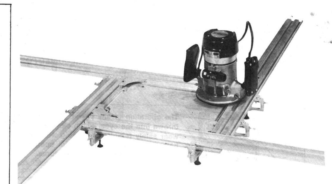
CRAFTSMAN . DRAWER and DOOR PANEL DECORATOR
Assembly Operation
(ROUTER NOT INCLUDED) ('C' CLAMPS NOT INCLUDED)
Sold by SEARS, ROEBUCK AND CO., Chicago, IL 60684 U.S.A.
IMPORTANT SAFETY INFORMATION – PLEASE READ
- 1. FOR YOUR SAFETY, ALWAYS WEAR IMPACT RESISTANT SAFETY GLASSES WHEN USING YOUR ROUTER
- 2. BE SURE ROUTER POWER CORD IS DISCONNECTED FROM POWER SUPPLY BEFORE ASSEMBLING, CHANGING CUTTERS, GRINDING WHEELS, SERVICING OR CHANGING ATTACHMENTS, ETC.
- 3. BE SURE ALL ADJUSTMENTS ARE PROPERLY SET AND SECURELY FASTENED.
- 4. KEEP WORK AREA CLEAN, AS CLUTTERED AREAS AND BENCHES INVITE ACCIDENTS.
- 5. KEEP CHILDREN AWAY AND ALL VISITORS A SAFE DISTANCE FROM THE WORK AREA
- 6. CHECK FREQUENTLY DURING OPERATION TO INSURE REQUIRED POSITION AND TO PREVENT HOLDING MECHANISM FROM BECOMING LOOSENED.
GENERAL
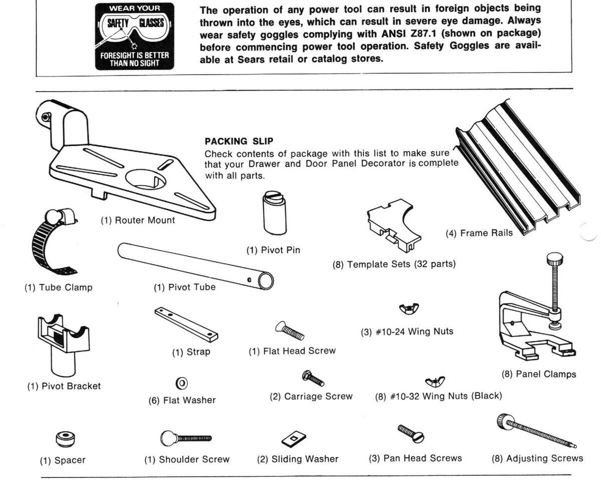
The Drawer and Door Panel Decorator (referred to as Panel Decorator) *is a device used with a router to make decorative router cuts on such things as cabinet doors and drawer fronts. Seven sets (four per set) of templates are supplied for making many different designs. An additional blank template set is supplied, which is used to hold wooden templates made by the user.
Included with this unit is a radius attachment which is used for routing arcs from 5" to 171/4" radii.
The maximum size panel which may be routed using this unit is 36" x 36" x 1".
For Sears routers, template guide bushings #9 25069 (not supplied with this unit) are required. Suitable guide bushings will be required for use with router other than Sears. These should be obtained from the manufacturer of the router.
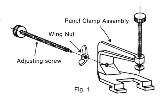
PRE-ASSEMBLIES
Refer to Figure 1. Spin the #10-32 wing nuts on the adjusting screws. Insert the adjusting screws and wing nuts into the clamps.
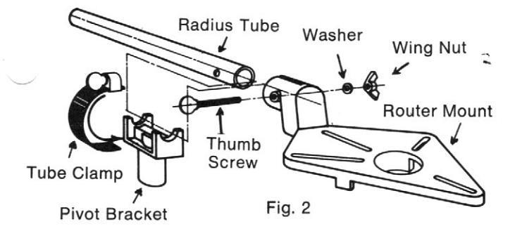
Refer to Figure 2. Insert the radius tube into the router mount making sure that the holes in the tube line up with the holes in the router mount. Insert the thumb screw, washer, and nut as shown. Tighten the nut and screw until the tube is tight in the router mount. Completely open the radius tube clamp. Insert the end of the clamp through the pivot bracket. Partially close the tube clamp. Insert the radius tube through the clamp and pivot bracket. Tighten the clamp such that the radius tube is secured to the pivot bracket in any position for now.
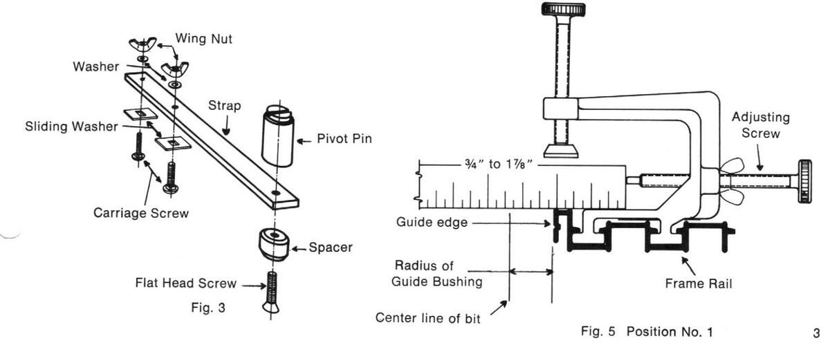
Refer to Figure 3. Secure the pivot pin and spacer to the strap using the 1/4-20 flat head screw. Loosely secure the two #10-24 carriage bolts, #10 washers, wing nuts, and sliding washers, into the strap as shown.
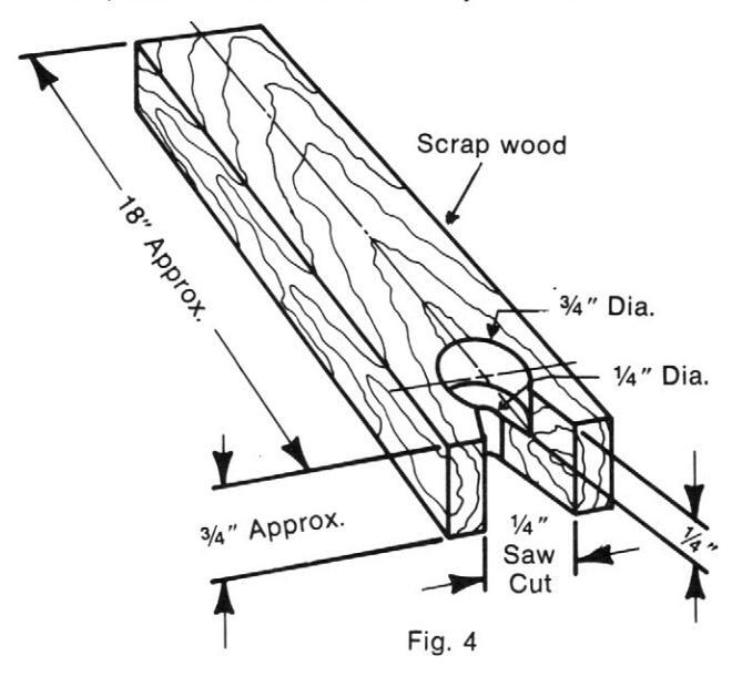
CLAMPING BLOCKS
Refer to Figure 4. In order to prevent the panel decorator from moving about when a design is being routed by one person, four wooden clamp blocks will need to be made and used. Using scrap wood, drill and cut the clamp blocks as shown. The use of these blocks will be discussed later.
The panel decorator is now ready for use.
ROUTING PANELS USING THE SUPPLIED TEMPLATES
Cut the panel to be decorated to the desired size, making sure that the ends and sides are square. Select the template set which matches the desired design. The template sets are lettered 'A' through 'H'.
Refer to Figure 5. Each frame rail has two positions into which the panel clamps slide. Using the 5%" diameter guide bushing, the center line of the router bit can be adjusted from 34" to 17%" from the edge of the panel when the panel clamps are in position 1, and from 17%" to 3" when the panel clamps are in position 2. Insert two of the panel clamps into each frame rail. (Small burrs on the ends of the frame rails may prevent the clamps from freely sliding into the rails. The burrs may be removed with a small knife or file.) Determine the desired distance from the edge of the panel that the cut is to be made. Subtract the radius of the guide from this distance and position the adjusting screws as shown. Tighten the wing nuts.

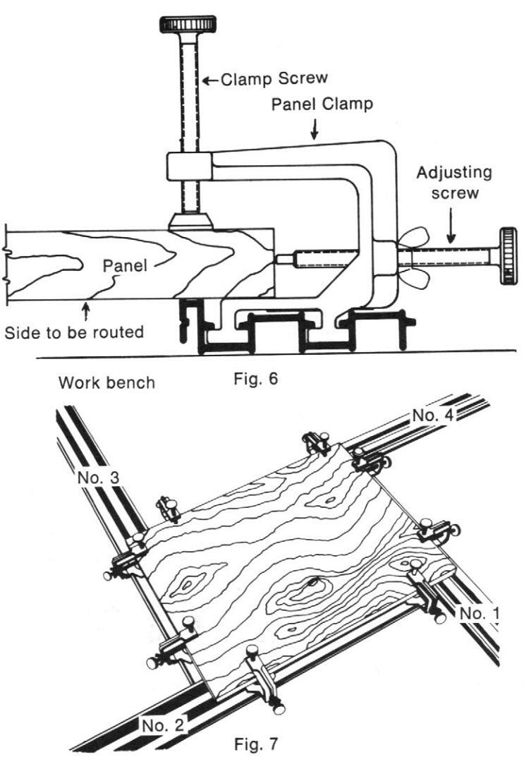
Refer to Figures 6 and 7. Lay the four frame rails and panel clamps on a flat surface in a square or rectangular fashion such that the heads of the clamp screws are pointing up. With the surface of the panel to be routed facing down, position the frame rails under the panel. Starting with No. 1 and 2 frame rails, position the frame rails such that the corner where the two rails meet is square and the adjusting screws are touching the edges of the panel. Snug the clamp screws in No. 2 frame rail. Moving in a clockwise direction, repeat for the other three frame rails. Check to make sure that the edge of panel is against the adjusting screws and the corners where the four frame rails meet are square and touching each other. For best results, the panel clamps should be about an inch from the corners.
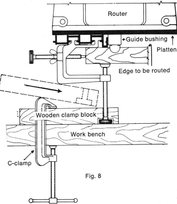
Refer to Figure 8. Turn the assembly over and rest the heads of the clamp screws on the work bench. Hold one of the wooden clamp blocks (discussed earlier) about ½" above the head of one of the clamp screws. Move the clamp block in until the ¼ diameter hole is against the threaded portion of the clamp screw. Lower the clamp block over the head of the clamp screw and 'C' clamp the clamp block to the work bench. Repeat for the other three clamp blocks.
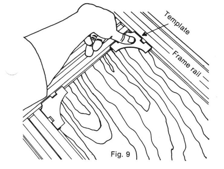
Refer to Figure 9. Place the four selected templates in the corners where the frame rails meet and press down until the templates snap into position.
Attach the desired guide bushing to router. Insert the selected router bit through the guide bushing and secure it in the router chuck. Refer to Figure 8. Adjust the router bit such that the end of the bit is extending below the router platen 5%" more than the depth of the cut to be made. Note: This adjustment is for the final cut. If the desired depth of cut is more than 1%", then more than one cut should be made.
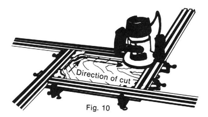
While holding the router such that the bit is slightly above the panel and the guide bushing is against one of the frame rails, turn the router on and allow the motor to come up to full speed. Slowly lower the router until the platen is resting flat on the frame rail. Guide the router through the cut in a right-to-left motion (clockwise) as shown in Figure 10. Maintain a slight amount of pressure on the router to insure that the platen remains flat on the frame rails and the guide bushing is touching the frame rails. Slowly move the guide bushing along the contoured edge of the templates. When the entire design has been routed, turn the router off and allow the motor to come to a complete stop before lifting the router from frame rail. This will prevent the work piece or frame rail from accidently being damaged. The panel may now be removed from the panel decorator for sanding and finishing. Note: If you feel a little practice would be helpful, before putting a bit into the router, set the platen flat on one of the frame rails and move it until the guide bushing is touching the frame rail. Moving in a rightto-left motion, guide the router through the entire design. This will be especially helpful in getting you acquainted with the feel of the router as it is moved along the four frame rails and corner templates.
RADIUS ATTACHMENT
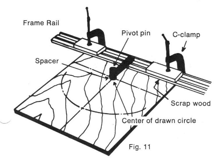
To use the radius attachment, one of the frame rails, four standard size 'C' clamps (not supplied with this unit), and the radius attachment assemblies will be needed. Refer to Figure 11. Locate the center of the arc to be routed and lightly draw a 13/16" diameter circle about this center. (A circle drawn around a penny is about 13/16" diameter). Position the strap about midway in one of the frame rails and tighten the nuts as shown in Figure 12. Position this assembly such that the spacer is in the center of the drawn circle. Clamp the frame rail to the panel with two 'C' clamps. Scrap wood should be used between the 'C' clamps and the frame rail to prevent damaging the frame rail, as shown in Figure 11.
Center your router on the router mount and secure it using three pan head screws and washers. If your router has a base platen, then it should be mounted with the router. If this is the first cut to be made, or it does not blend into another cut, then the bit should be adjusted such that it is slightly above the panel when the router mount is resting flat on the panel. Do not change the bit setting if the cut to be made is to blend into another cut which has already been made.
Refer to Figure 12. Slide the pivot bracket over the pivot pin. The router mount should be resting flat on the panel. Loosen the tube clamp and adjust the distance between the pivot bracket and the router mount to obtain the desired radius of the arc to be routed, and retighten the tube clamp. If the arc to be routed blends into a previously routed design, check the beginning and end of the arc to assure that the radius attachment is poistioned correctly. If the arc does not blend into the previously routed design, then minor adjustments will be required for the radius setting, and/or the spacer location.
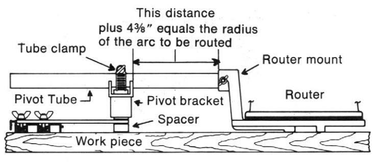
Fig. 12
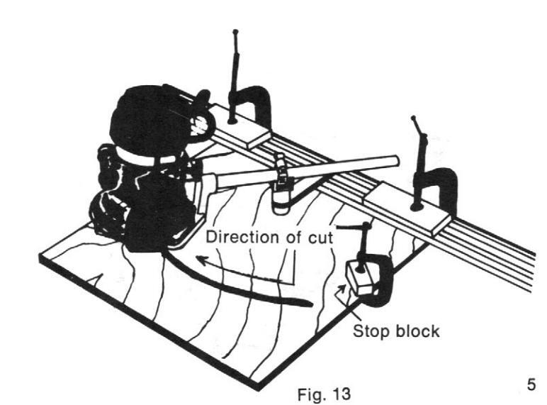
Refer to Figure 13. Stop blocks (scrap wood) should be used at the beginning and end of the arc. Position the router such that the bit is at the beginning of the arc. Place a stop block such that it is touching the side of the router mount. Clamp the stop block to the panel. Repeat for the end of the arc.
Clamp the panel to a work bench to prevent it from moving about. The radius attachment is now ready for use.
Slide the pivot bracket over the pivot pin. Hold the router at the start of the arc such that the bit is slightly above the panel. Turn the router on and allow the motor to come up to full speed. Lower the router until the router mount is resting flat on the panel. Swing the router in a clockwise motion until the router mount touches the end stop block. Turn the router off and allow the motor to come to a complete stop before removing it from the panel.
BLANK TEMPLATES
Four blank templates (designated by the letter H) are used for mounting a special shape template made by the user. Cut the panel to the desired size and mount it on the panel decorator per previous instructions. Snap the four blank templates into the corners where the frame rails meet. Cut a piece of 1/4" plywood such that it fits freely into the four templates. The top surface of the plywood should be flush with the top of the frame rails. Remove the plywood and templates from the panel decorator.
Draw the desired design on the top surface of the plywood. Figure 14 shows an example of a finished template. After completing the design layout, saw the plywood to match the design. Sand the sawed edge smooth.

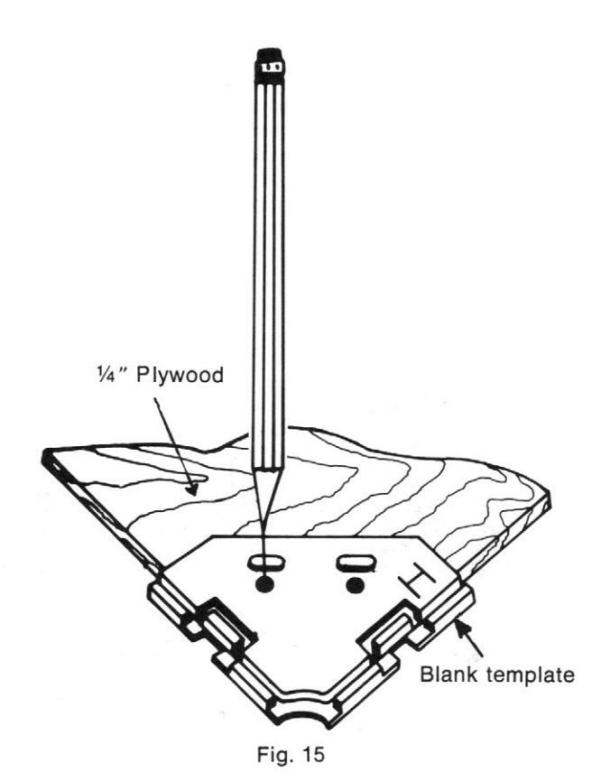
Refer to Figure 15. Position one of the blank templates at one corner of the plywood and draw the hole locations onto the plywood as shown. Repeat for the other three corners. Drill eight holes for No. 10 flat head machine screws. Countersink the holes on the top surface such that the heads of the screws are slightly below the surface of the plywood. Mount the blank templates to the plywood using eight No. 10 x 1/2 flat head machine screws and hex nuts (not supplied with this unit). Do not tighten the screws for now.
Refer to Figure 14. Press the template assembly into the panel decorator until the four blank templates snap into the frame rails. Without removing the template, tighten the screws. The design may now be routed.
While holding the router such that the bit is slightly above the panel, and the guide bushing is touching the plywood template edge, turn the router on and allow the motor to come up to full speed. Lower the router until the platen is resting flat on the template surface. Moving in a clockwise motion, guide the router along the template edge until the design is complete. Turn the router off and allow the motor to come to a complete stop before removing.
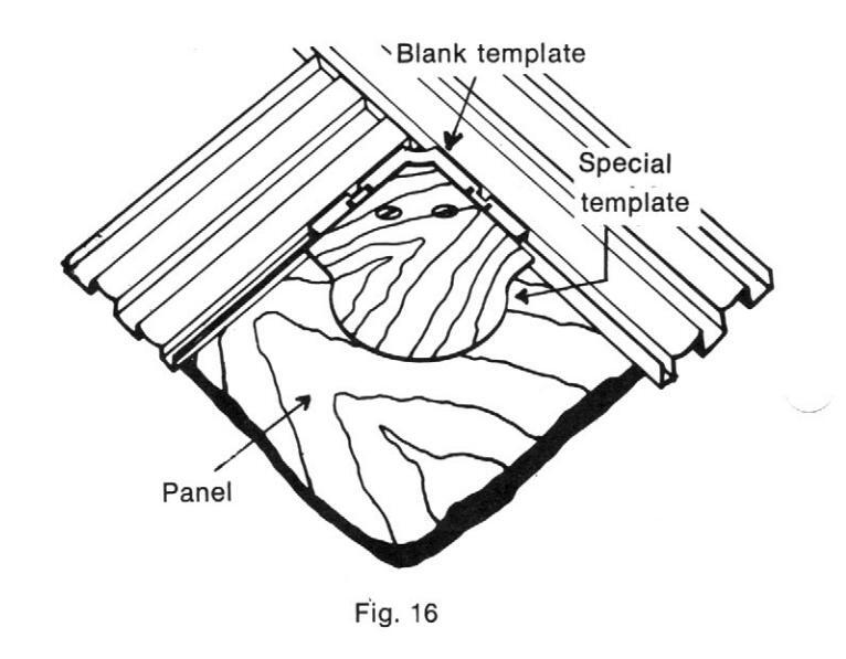
The blank templates may also be used to hold special corner templates made by the user as shown in Figure 16. The special corner templates are to be made from ¼" plywood and mounted to the blank templates as discussed earlier. After snapping the template assemblies into the frame rails, the panel may be routed per earlier instructions.
ROUTER BITS AND FINISHED EXAMPLES
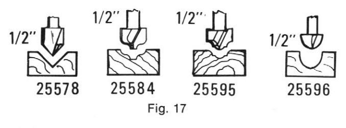
Any of the end cutting router bits may be used with the Panel Decorator. Carbide cutting edges last 15 times longer than high speed steel on abrasive materials such as plywood, chipboard, and Masonite®. Figure 17 shows four bits which are often used with the Panel Decorator.
Figures 18 through Figure 27 show examples of some finished panel designs. The letters at the top and bottom of the panel denote which templates were used in making the design. Letters in parentheses denote alternate templates which could have been used to make similar designs.
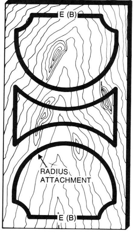
Fig. 18
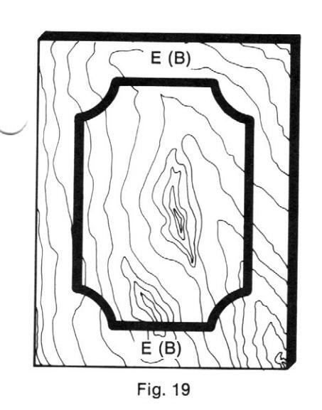
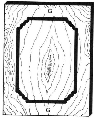
Fig. 20
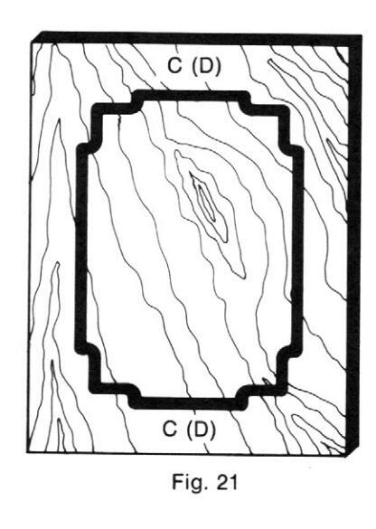
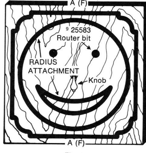
Fig. 22
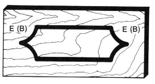
Fig. 23
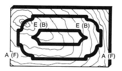
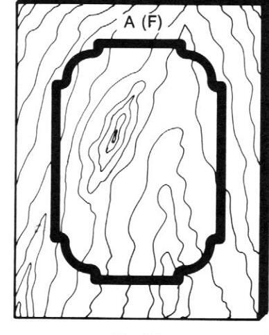
Fig. 25
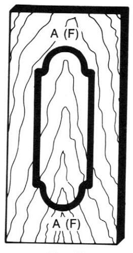
Fig. 26
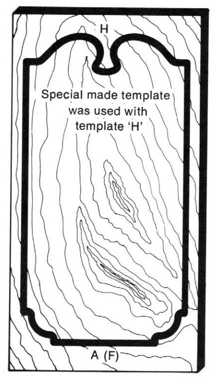
Fig. 27
7

OWNERS MANUAL
CATALOG NO. 25472
CRAFTSMAN . DRAWER and DOOR PANEL DECORATOR
ALWAYS MENTION CATALOG NUMBER 25472 WHEN COMMUNICATING WITH US REGARDING YOUR CRAFTSMAN DRAWER & DOOR PANEL DECORATOR
Sold by SEARS, ROEBUCK AND CO., Chicago, IL 60684 U.S.A.


 Loading...