

sears owners manual
Model No. 171.25183
CRAFTSMAN° ROUTER TABLE POWER SWITCH
AssemblyOperation
WARNING
Read and follow all instructions carefully. KEEP THIS MANUAL FOR FUTURE REFERENCE.
Sold by Sears, Roebuck and Co., Hoffman Estates, IL. 60179

WARNING: FAILURE TO HEED ALL ASSEMBLY, SAFETY, AND OPERATING INSTRUCTIONS AND WARNINGS REGARDING THE USE OF THIS PRODUCT, ALONG WITH THOSE OPER-ATING INSTRUCTIONS AND WARNINGS IN THE ROUTER AND THE ROUTER TABLE OWNER'S MANUALS, CAN RESULT IN SERIOUS BODILY INJURY.
GENERAL SAFETY INSTRUCTIONS FOR POWER TOOLS
GENERAL :
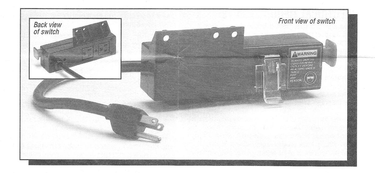
The Power Switch is designed to be used with most Sears Router Tables and Routers. It provides the convenience of an "on-off" switch at the front of the table, thus eliminating the need to reach underneath the table to turn the router on and off. (NOTE: The electronic routers, #1750 and #27501, are a special case which is explained in the section ROUTER AND SWITCH BOX OPERATION.) The Power Switch also provides for optional simultaneous "on-off" control of an additional accessory such as a light, vacuum, etc. The switch incorporates an internal, resettable circuit breaker to provide protection in overload situations.
ELECTRICAL REQUIREMENTS:
In the event of a malfunction or breakdown, grounding provides a path of least resistance for electric current to reduce the risk of electric shock. This switch box is equipped with an electric cord having an equipment grounding connector and a grounding plug. The plug must be plugged into a matching outlet that is properly installed and grounded in accordance with all local codes and ordinances.
Do not modify the plug provided if it will not fit the outlet; have the proper outlet installed by a qualified electrician.
Improper connection of the equipment grounding conductor can result in risk of electric shock. The conductor with insulation having an outer surface that is green with or without yellow stripes, is the equipment grounding conductor. If repair or replacement of the electric cord or plug is necessary, do not connect the equipment grounding conductor to a live terminal.
Check with a qualified electrician or service person if the grounding instructions are not completely understood, or if in doubt as to whether the switch box is properly grounded.
Use only 14 gauge or larger, 3-wire extension cords that have 3-prong grounding plugs and 3-hole receptacles that accept the tool's plug.
Repair or replace a damaged or worn cord immediately.
The electrical outlet on the back of the switch box will accept either a 2-prong plug from a DOUBLE INSULATED router or accessory, or a 3-prong grounding type plug.
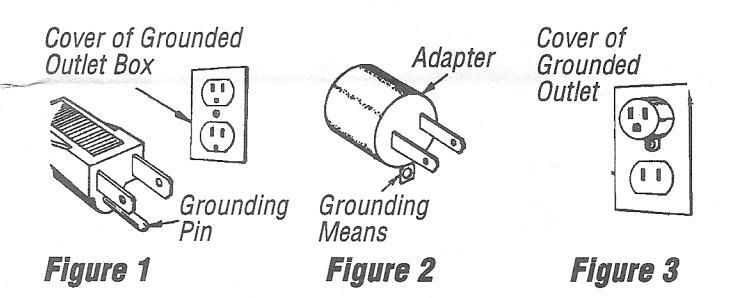
This switch is intended for use on a circuit that has an outlet as illustrated in Figure 1. The switch box has a grounding plug as illustrated in Figure 1. A temporary adapter as illustrated in Figure 2 may be used to connect this plug to a 2hole receptacle as shown in Figure 3, if a properly grounded outlet is not available.
The temporary adapter should be used only until a properly grounded outlet can be installed by a qualified electrician. The green colored rigid ear or lug extending from the adapter must be connected to a permanent ground, such as a properly grounded outlet box.
WARNING:
DO NOT PERMIT FINGERS TO TOUCH TERMINALS OF THE PLUG WHEN INSTALLING TO OR REMOVING FROM THE OUTLET. IF NOT PROPERLY GROUNDED, THIS POWER TOOL CAN PRESENT THE POTENTIAL HAZARD OF ELECTRI-CAL SHOCK, WHICH CAN POSSIBLY RESULT IN DEATH; PARTICULARLY WHEN USED IN A DAMP LOCATION, IN PROXIMITY TO PLUMBING, OR OUT OF DOORS. IF AN ELECTRICAL SHOCK OCCURS, THERE IS ALWAYS THE POTENTIAL OF A SECONDARY HAZARD SUCH AS YOUR HANDS CONTACTING THE ROUTER BIT.
THE SWITCH BOX IS TO BE USED ONLY WHEN PROPERLY ASSEMBLED TO THE ROUTER TABLE AND WITH A ROUTER WHICH HAS ALSO BEEN PROPERLY INSTALLED ON A PROPERLY ASSEMBLED ROUTER TABLE.
READ AND UNDERSTAND THIS COMPLETE INSTRUCTION BOOK BEFORE USING THIS PRODUCT
ASSEMBLY: Switch Box to Router Table
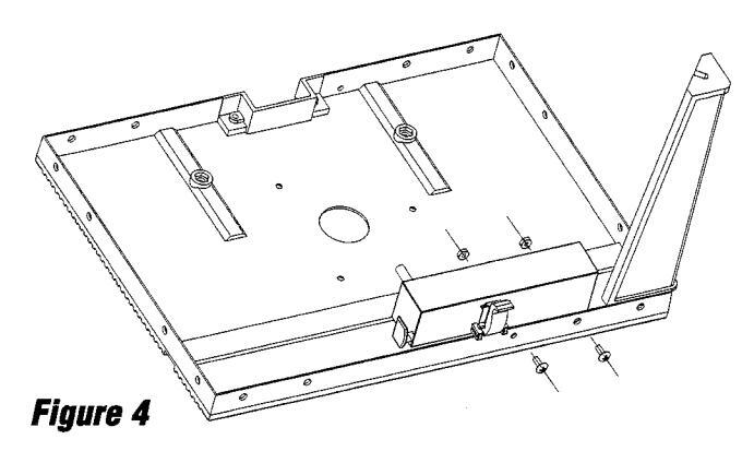
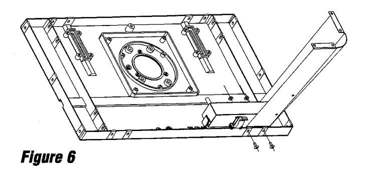
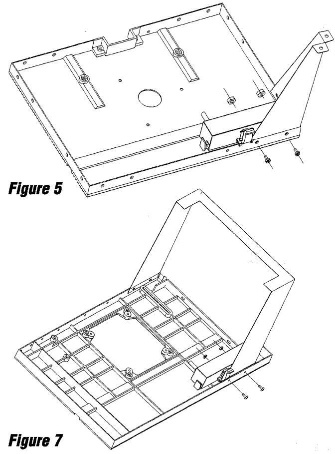
Figures 4, 5, 6 and 7 illustrate assembly of the Switch Box to the different types of Router Tables. Use the Figure that most closely resembles your Router Table and follow the instructions below.
NOTE: If your router table has been previously assembled complete steps 1 through 5.
- 1) DISCONNECT THE POWER CORD TO THE ROUTER FROM THE ELECTRICAL OUTLET.
- 2) Remove any router bit that is now in the router.
- 3) Lower the router so the collet assembly is below the top surface of the table.
- 4) Remove all accessories, such as guards, miter gauge, and fences from the table.
- 5) Place the router table, top side down, on a flat surface and if necessary, remove the two screws, two nuts and washers, if any, holding the left leg (when the router table is upright) to the front of the router table. Discard the removed hardware. It is not necessary to remove the leg from the table.
Position the switch box on the underside of the table as shown in the appropriate Figure. The switch box is on the inside of the table. Using the two screws and nuts provided with the switch box secure it in place on the table.
SECURELY TIGHTEN ALL SCREWS AND NUTS.
Detail of the underside of the table is not necessarily representative of all router table models.
If you are assembling the router table for the first time, continue with the assembly of the router table beginning with the section addressing the assembly of the legs to the table.
NOTE: With the router installed on the router table, plug the router power cord into one of the outlets on the switch box. If desired, the power cord from an additional accessory such as a vacuum or light may be plugged into the other outlet at this time.
WARNING: MAKE SURE THAT POWER CORD TO THE SWITCH BOX IS NOT PLUGGED INTO AN ELECTRICAL OUTLET WHILE DOING THIS. MAKE SURE THE EXCESS ROUTER AND SWITCH BOX POWER CORDS DO NOT AND CANNOT COME IN CONTACT WITH THE INSTALLED ROUTER BIT OR ANY MOVING PARTS OF THE ROUTER.
It is recommended that the excess router power cord be formed into a coil and wrapped with two pieces of friction tape or a strong cord, on opposite sides of the coil. Allow some slack so that the cord is not stretched when plugged into the switch box.
MAKE SURE THAT POWER CORDS DO NOT AFFECT ANY ROUTING OPERATION.
WARNING: DO NOT PLUG CORD FROM SWITCH BOX INTO AN ELECTRICAL OUTLET AT THIS TIME.
3
SWITCH BOX OPERATION:
This section explains the operation and features of the switch box prior to plugging the power cord into an electrical outlet. The intent is to familiarize the user with the switch box operation without actually turning on the router.
The switch box incorporates two positive safety features to prevent inadvertent switching ON of the router and unauthorized and possibly hazardous use by others. Inadvertent switching ON of the router is prevented by the clear plastic switch cover. The cover must be raised and the switch manually toggled to the ON position to start the router. Also, the safety key can be removed to disable the switch box by "locking" the switch in the OFF position, thus preventing unauthorized and possible hazardous use.
In an emergency, the switch can be turned OFF by slapping or striking the switch cover with the hand.
To operate the switch box, proceed as follows:
NOTE: Because the switch also functions as a circuit breaker, the ON position is labeled RESET on the switch. For clarity this instruction uses ON in place of RESET.
1) Insert the safety key into switch box. SEE FIGURE 8.
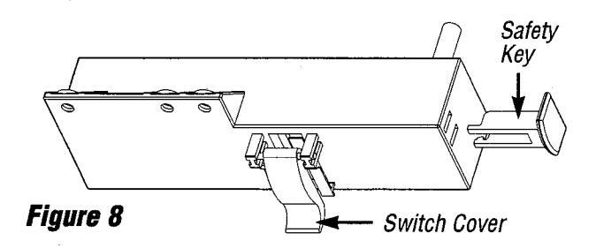
- 2) To turn router ON insert finger under switch cover and toggle switch to ON position.
- 3) To turn router to OFF press switch cover.
NEVER LEAVE ROUTER UNATTENDED UNTIL IT HAS COME TO A COMPLETE STOP.
4) To lock switch to OFF position remove key from switch box.
With the key removed from the switch box, the switch cannot be toggled to the ON position.
WARNING: BEFORE PROCEEDING ANY FURTHER, MAKE SURE THE SWITCH ON THE ROUTER IS IN THE "OFF" POSI-TION AND THE SWITCH LEVER IS IN THE "OFF" POSITION.
ROUTER AND SWITCH BOX OPERATION:
This section explains operation of the switch box with the power cord plugged into an electrical outlet. The router will turn ON when the switch is toggled to the ON (or RESET) position.
- Position the ON-OFF switch on the router in the ON position. On certain routers this will require the use of the Switch Trigger and "Lock-On" button. (Consult router owner's Manual.) MAKE SURE SWITCH BOX LEVER IS IN THE OFF POSITION WHEN DOING THIS.
- 2) To turn the router ON, slide finger under the switch cover and toggle the switch to the ON position as described in the previous section.
- 3) To turn the router OFF, press the switch cover as described in the previous section.
SPECIAL NOTE TO OWNERS OF MODEL NOS. 1750 AND 27501 ROUTERS:
Because these routers come with a special "Lock-On" feature that will not permit it to be turned ON by the switch box, but can be turned OFF by the switch, the following method of operation is to be used:
- Toggle the switch box switch as described in the previous section. The router should NOT start even though the trigger lock is in the "Lock-On" position. (Consult Router Owner's manual.)
- 2) To start the router, depress the trigger and engage the "Lock-On" button located on the side of the handle. THE ROUTER SHOULD START IMMEDIATELY.
If the router switch is already in the "Lock-On" position (The "soft" and "1/4 inch" indicator lights will be flashing - consult Router Owner's Manual), unlock the trigger. Then depress the trigger, THE ROUTER WILL START IMMEDIATELY , and engage the "Lock-On" button on the side of the handle.
- 3) To turn the router OFF, press the switch box switch cover.
- 4) To restart the router, it will always be necessary to perform step "1" followed by step "2".
NOTE: In the event of an overload situation, the internal switch box circuit breaker may trip and interrupt power to the router and/or vacuum by toggling the switch to the OFF position. If this occurs:
- 1) Unplug the router power cord from the wall outlet.
- 2) Clear the work piece from the router table.
ROUTER AND SWITCH BOX OPERATION:
continued
- 3) Correct the cause of the overload situation, i.e. attempting to remove too much stock or too high feed rate.
- 4) Restart router as described under ROUTER AND SWITCH BOX OPERATION
WARNING: FOR YOUR OWN SAFETY AND THE SAFETY OF OTHERS, WHEN THE ROUTER TABLE IS NOT IN USE, ALWAYS:
- 1) Toggle the switch lever to the OFF position and remove the key.
- 2) Turn the router OFF.
- 3) Unplug the switch box power cord from the electrical outlet.
- 4) Remove the router bit from the router.
- 5) Make sure the router collet assembly is below the top of the router table.
- 6) Store the switch box key in a safe location where it is not available to children or other unauthorized persons.
WARNING: IN THE EVENT OF A POWER FAILURE, BLOWN FUSE, OR ROUTER "STALLING OUT" WHILE ROUTING, PUSH THE SWITCH COVER TO TOGGLE THE SWITCH TO THE OFF POSITION AND REMOVE THE KEY FROM THE SWITCH BOX UNTIL THE SOURCE OF THE PROBLEM HAS BEEN CORRECTED. ADDITIONALLY, UNPLUG THE SWITCH BOX FROM THE ELECTRICAL OUTLET.
When corresponding, always give the following information as shown in the list.
- 1. The PART NUMBER
- 2. The PART DESCRIPTION
- 3. The MODEL # 171.25183
- 4. The ITEM NAME ROUTER TABLE POWER SWITCH
Printed In U.S.A. 7/96


 Loading...