

OPERATING INSTRUCTIONS AND PARTS LIST FOR CRAFTSMAN 8 INCH BENCH SAW
Model 103.23831
ASSEMBLING:
Guard and Splitter
Slide the notched ends of the splitter into po on between the face of the splitter bracket No. 37418 and the dished washer No. 18448, and between the splitter spacer No. 37646 and dished washer No. 18448 located just behind the saw blade. Tighten the wing nut X454. When properly installed, the splitter will be held firmly in place and in line with the saw blade.
Fence and Miter Gage
Install as shown in figure 1.
Motor Alignment Rod
The 5/16 x 41/2 inch motor alignment rod fits into the hole in the back of the splitter bracket. Insert the rod as far as it will go into the bracket and tighten the set screw.
INSTALLATION OF SAW:
There are four 5/16 diameter holes provided in the base of the saw through which the tool should be fastened securely with screws or bolts to a well built work bench. A large hole in the bench below the blade will allow saw dust to escape.
The Motor Mount Brackets should be installed as shown in figure 2.
- 1. Set the saw blade at 0 inches elevation and 0 degrees tilt. (See paragraph headed "Controls")
- 2. Assemble motor rail, motor mount, and brackets as shown.
3. Draw a line on the bench 51/4 inches from the rear of the saw base. (Measure at two points 12 inches apart to be sure that the line is parallel to the rear of the base.)
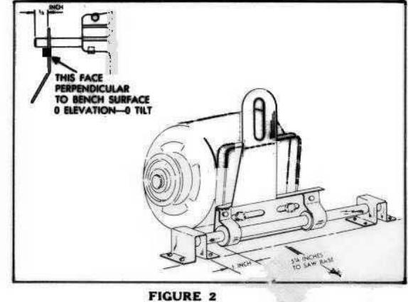
- 4. With the motor alignment rod extending through the motor mount slot, fasten the two brackets securely to the bench with their front edge on the line drawn 51/4 inches from the rear of the saw base. Allow one inch clearance at the left hand end of the motor rail as shown.
- 5. Bolt your motor to the mount so that the motor pulley will be in line with the saw pulley when the motor alignment rod is through the bracket slot.

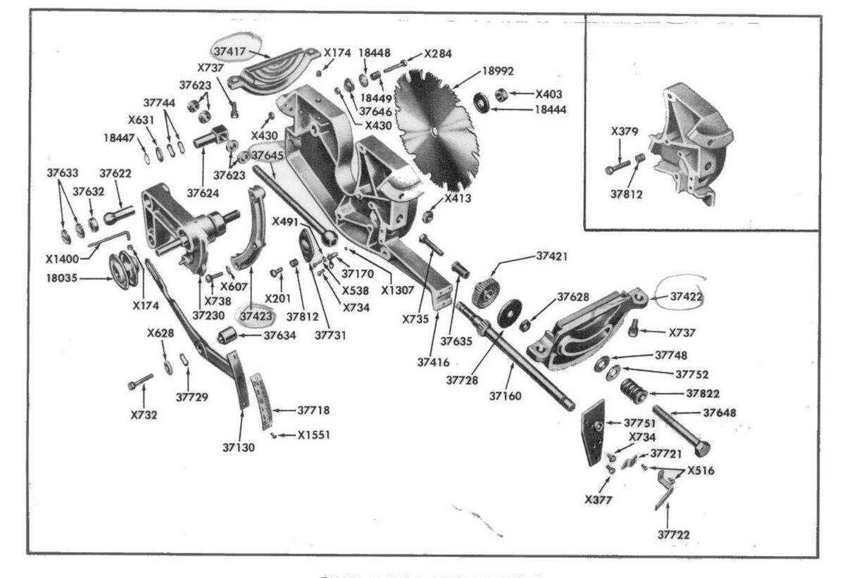
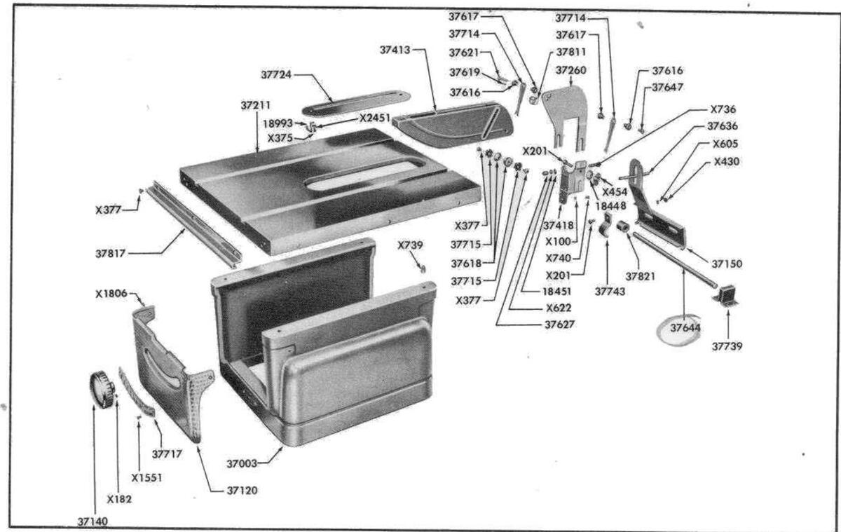
TABLE ASSEMBLY
tion) and low position. The front pair of stops control the high position while the rear pair stop the blade at low position.
The Blade Must Be Parallel with the Miter Slots in the Table to Get a Straight Cut. (See figure 4.) Adjustment, if necessary, may be made as follows:
- Extend the blade fully and set it at right angles (0 degrees) to the table.
- Slide the fence to the center of the table until it just touches the blade. (Fence must be parallel to the miter slot when it touches blade.)
- 3. Lock the fence.
- Loosen the 2 bolts holding each trunnion No. 37417 and No. 37422 to the lower table surface. (4 bolts total.)
- 5. Shift the complete mechanism until the blade is flat against the fence.
- 6. Retighten the four trunnion screws-front pair first.
- 7. Check this adjustment by measuring again from the marked blade tooth to the miter slot as previously explained.
The Fence Must Lock Parallel with the Miter Slots. Using one hand on the front end of the fence, slide the fence to the edge of the miter slot. Push the lock handle down slowly. If fence isn't parallel to miter slot adjust as follows:
- 1. Loosen the two screws in the lower surface of the front fence end.
- 2. Release the fence lock handle.
- 3. Hold the fence flush with the miter slot edge. Turn both screws up just snug. Then tighten each one securely.
- 4. Check the adjustment by sliding the fence away from the slot and returning several times to see if it locks parallel each time.
The Fence Must Be Square with the Table Surface. Adjust by loosening the screws holding the fence slide bar to the table. Slide the bar up or down at either end enough to square the face of the fence with the table. Retighten the screws.
The Arbor Tilt Tension Spring No. 37822 provides tension to keep the mechanism tilted at any angle, thus eliminating the need for a manual control lock. After the tool is "broken in," you may find it necessary to increase this tension. Loosen the lock nut X413 and turn the bolt 37648 until enough tension has been applied. Retighten the lock nut.
CARE OF THE BLADE:
Keep the blade teeth sharp and properly set.
To sharpen the blade:
- 1. Lower the blade until an oil stone laid on the table will just touch the teeth. Rotate the blade backward by hand until the ends of all the small cutting teeth have been touched.
- 2. File the gullets (space between teeth) of all teeth of the same shape to a uniform depth and width. Maintain the original shape, bevels, and dimensions. Avoid sharp corners or nicks in the gullets between the teeth.
- 3. The top one-quarter of each cutting tooth should be set at an angle of approximately 10
degrees. The set should be uniform and should alternate from left to right on successive teeth. The large raker teeth require no set—they should be kept approximately 1/64 inch shorter than the cutting teeth.
4. File the bevel of each cutting tooth—15 to 20 degree bevel on the inside front face of each tooth. Maintain the original bevel angle and be careful not to shorten the teeth.
Blade Wobble is often noticed at slow speeds when starting or stopping the saw. If this does not disappear at full speed, check the saw blade and clamp washers for dirt or saw dust on the clamping surfaces.
Gummy residue can generally be removed with kerosene.
OPERATION:
The blade provided with this saw may be used for both cross-cutting and ripping. However, if continuous ripping or continuous cross cutting is planned, a rip blade or cross cut blade will operate much more efficiently.
For proper chip clearance and best general results, the blade should project through the work-piece approximately 1/4 inch.
Saw warped stock with the concave or hollow face down.
Support long work as it leaves the rear of the table. Avoid back tracking on a cut.
Do not force material into the blade too fast. Use a straight, direct, steady feed which does not overtax the cutting capacity of the blade.
SAFETY:
While the bench saw is one of the most widely used woodshop power tools, it is by nature of its general design, one of the most dangerous in the hands of inexperienced or careless operators. The bench saw is not, however, an unsafe tool when used with common sense and good judgment.
Use a push block rather than letting the hands get closer than 3 inches to the blade on narrow cuts.
Keep the splitter and anti-kickback units in place whenever possible. Never hold the hands over the blade when making blind groove type cuts. Stand to one side when completing a cut. A loose piece caught by the blade can fly back with surprising force.
Always stop the saw when removing waste stock from near the blade, when making adjustments, or when changing settings.
Do not wear dangling neck ties, loose baggy sleeves, etc., while operating power tools.
The guard is supplied with this saw for your safety —use it to its best advantage!
ACCESSORIES for this saw will be listed in your catalog or can be obtained from your nearest Sears Retail Store. An interesting and instructive booklet entitled "The Bench Saw and Jointer" is also available. It explains many handy special operations which may be performed on your bench saw.
6. Block the motor in position so that the alignment rod extends through the mount slot 1/2 inch. Measure around the outside of the pulleys (not in the groove) with a flexible tape to determine the length of belt needed.
Check before Operation!
- 1. The motor alignment rod must project at least 1/4 inch through the mount slot with the blade retracted and tilted 45 degrees. This setting should be checked often during operation. As the belt wears or stretches, loosen the set screw and pull the alignment rod out of the bracket the amount needed.
- The motor mount must not strike the motor mount brackets at either end of the motor rail at 0 or 45 degrees tilt.
- 3. Be sure that the teeth of the blade point toward the front of the saw and the top of the blade turns toward the front.
MOTOR:
For general home workshop use, a 1/2 horsepower 3450 R.P.M. motor will provide adequate speed and power. However, to enable you to take full advantage of the rugged performance features and full cutting efficiency of this saw, especially for heavy duty work, a 3/4 horsepower 3450 R.P.M. motor should be used.
SPEED:
A 21/2 inch diameter pulley installed on the 3450 R.P.M. motor will drive the saw at the recommended sr 1-4500 R.P.M.
BELT:
If your motor shaft is approximately 4 inches from the bottom of the base of the motor, a 1/2" x 40" standard V-belt should fit the installation described on p. 2.
LUBRICATION:
The precision ball bearings used on the saw arbor have been packed with lubricant and sealed at the factory. They should require no further attention for the life of the bearings.
To maintain the smooth, easy operation of the controls, oil the following points occasionally:
- 1. The guide, No. 37423 at the front of the arbor support.
- 2. The guide ways of the front and rear trunnions, Nos. 37422 and 37417.
- 3. The elevation screw No. 37645.
- 4. The motor rail No. 37644.
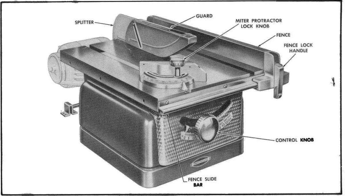
CONTROLS:
The Control Knob raises the saw from 0 to 21/2 inches above the table level when pushed in and turned. It tilts the saw 0 to 45 degrees when pulled out and turned.
CAUTION:
This saw has an extra long spindle for greater dado capacity. If the blade is extended more than 23/8
inches according to the depth of cut gage, the spindle will strike the table insert when the saw blade is tilted.
The Angle of Tilt is shown by a pointer on the scale just below the control knob.
The Depth of Cut Gage and Pointer can be seen through the curved slot to the left of the control knob.
The Fence Lock Handle when down clamps the fence at both ends of the table. Raise the handle to unlock and move the fence to any point across the table.
The Miter Protractor face is a guide surface for cross cutting or diagonal cutting to a definite angle. The protractor may be used on either side of the blade at any angle or depth of cut setting. The angle is shown by the pointer on the calibrated scale on the protractor head. The lock knob clamps the head in the selected position.
ADJUSTMENTS:
The following items may require adjustment due to rough handling during shipment.
The Blade Tilt Stop Screw No. X379 located just behind the front trunnion on the left side of the body casting stops the tilt mechanism when the blade is at right angles to the table.
The Pointer for the Tilt Scale should indicate 0 degrees when the blade is at right angles to the table.
The Depth of Cut Pointer should be set at 0 when the blade is lowered with the teeth just flush with the table surface.
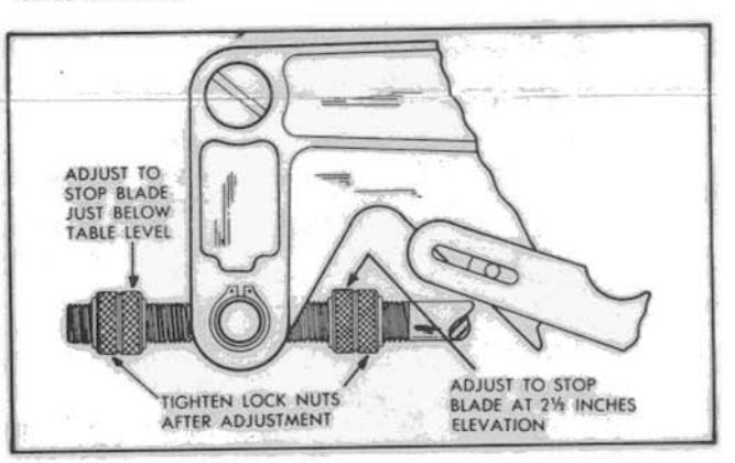
FIGURE 3
The Elevation Limit Stop Nuts shown in figure 2 automatically stop the saw at high (21/2 inch projec

FIGURE 4
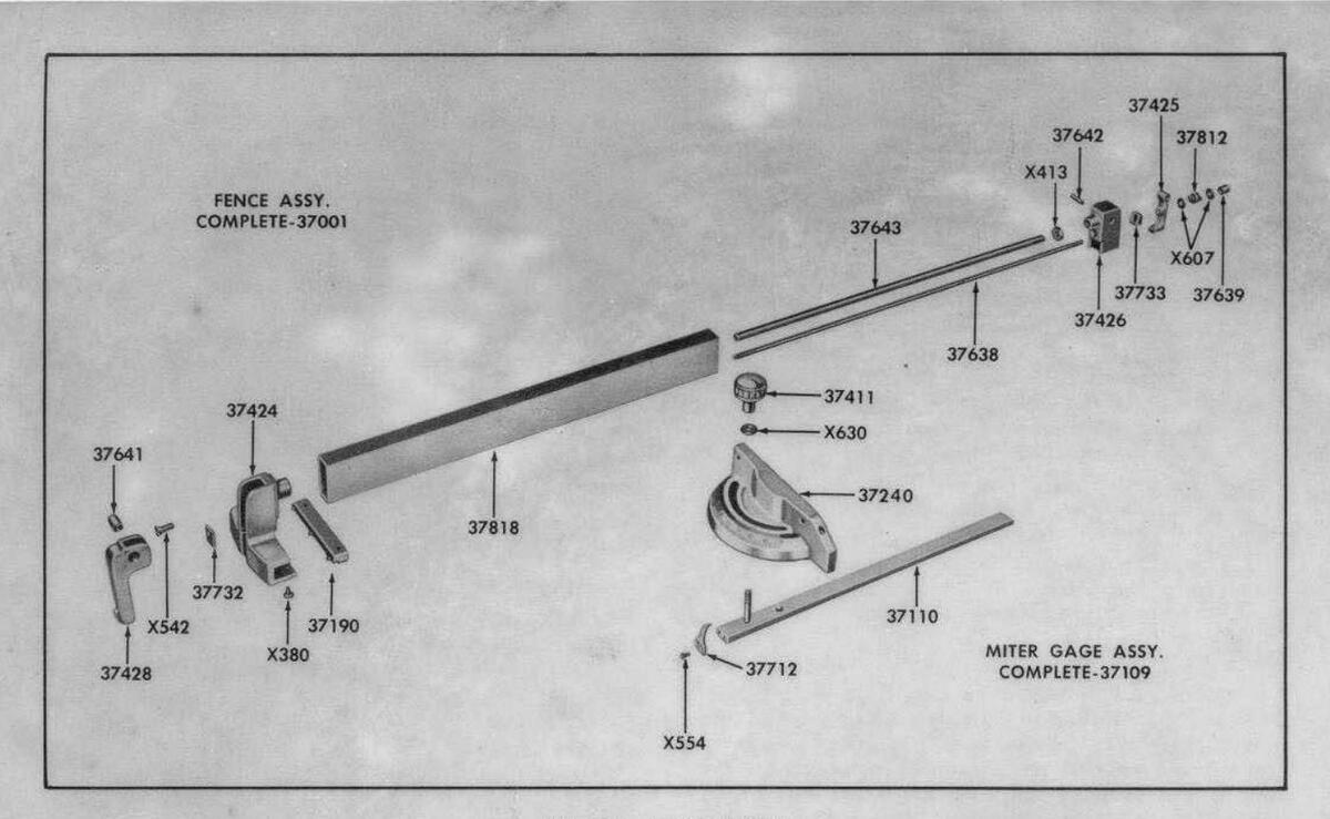
FENCE ASSEMBLY
Parts List
| Prepaid | Prepaid | Prepaid | ||||||
|---|---|---|---|---|---|---|---|---|
| Selling | Selling | D. D | Selling | |||||
| Part No. | PART NAME | Price | Part No. | PART NAME | Price | Part No. | PART NAME | Price |
| Each | Each | Lach | ||||||
| 18035 | Pulley with set screws, | $ .80 | 37639 | Fence lock rod nut | .$ .20 | X-403 | Hex nut 1/2-20 jam nut | .$ .10 |
| 18444 | Saw clamp washer | 15 | 37641 | Fence lock handle pivot pin. | 20 | X-413 | Hex nut % | |
| 18447 | Retaining ring | 15 | 37642 | Fence lock clamp pivot pin. | 15 | X-430 | Hex nut 1/4 20 | 10 |
| 18448 | Dished face splitter washer. | 15 | 37643 | Fence rod | 75 | X-454 | Wing nut 1/4-20 | 15 |
| 18449 | Splitter clamp tension spring | g15 | 37644 | Motor rail | 75 | X.491 | lam nut No. 6-32 | 10 |
| 18451 | Spring washer | 15 | 37645 | Saw elevation shaft | . 1.50 | ¥ 516 | Machine ecrew No 8-32 x 1 | 1 |
| 18992 | 8 inch diameter combination | on | 37646 | Splitter spacer | 20 | A-310 | round head | .10 |
| blade. Purchase from neare | st | 37647 | Guard slide pin screw | 15 | V 639 | Mashing seren No. 6 37 v 1 | ||
| Sears retail or mail order sto | re | 37648 | Arbor tilt tension bolt | 20 | V-330 | Machine screw No. 0-12 x 7 | 2 10 | |
| 18993 | Table insert clip | 37712 | Miter protractor pointer | 15 | N | round nead | ||
| 37001 | Fence assembly, complete. | 10 00 | 37714 | Anti-kickback pawl | 15 | X-342 | Machine screw % 20 x % na | 10 |
| 37003 | Rase | 11.00 | 37715 | Saw guard tension cone sprin | a .15 | head | 10 | |
| 37109 | Miter gage assembly comple | te 5.00 | 37717 | Arbor tilt scale | 30 | X-554 | Machine screw No. 6-32 | x |
| 37110 | Miter har | 2.50 | 37718 | Depth of cut scale | 15 | and the second second | 5/16 fillister head | 10 |
| 37120 | Front nanel with tilt ecale | 4 60 | 37721 | Depth of cut pointer | 15 | X-605 | Lock washer 1/4 inch | 10 |
| 37130 | Elevation indicator area wi | +h 7.00 | 37722 | Arbor tilt pointer | 15 | X-607 | Plain washer ¼ 1.D. x 19/3 | 2 |
| 37130 | Lievation indicator and wi | 60 | 37724 | Table insert | 1 10 | O.D | 10 | |
| 27140 | scale | 00 | 27729 | Washes | . 1.10 | X-622 | Plain washer 17/32 LD, x 7 | 4 |
| 37150 | Handwheel with set screws. | 4.43 | 27720 | washer | 1 12 | 0.0 | 10 | |
| 37130 | Motor rail guide | . 1.30 | 27721 | Spring washer | 13 | X.628 | Plain washer % ID + % OF | ) 10 |
| 3/100 | Shaft with gear | 1.00 | 27722 | Tension plate | X 630 | Plain washer 25/64 ID x 3 | ||
| 3/1/0 | Control shaft tension sprin | ng | 27722 | Fence lock handle friction plat | e .15 | X-030 | OD Washer 20/04 LD. X 7 | 4 15 |
| with screw | 20 | 21122 | rence lock rod tension spring | 12 | 34 1.01 | 1 11 | ||
| 37190 | Fence slide | 1.00 | 3//39 | Motor rall bracket | 50 | X-031 | Plain washer 41/04 LD. X | 1 10 |
| 37211 | Table | 26 00 | 31743 | Motor rail bushing clip | 25 | Q.D | 10 | |
| 37230 | Spindle support with bearing | 7.50 | 37744 | Spring washer | 15 | X-732 | Machine screw 1/4-20 x 11/2 | 2 |
| 37240 | Miter Protractor | . 325 | 37748 | Washer fibre | 15 | hex head with internal loc | k | |
| 37260 | Splitter | 1.30 | 37751 | Control shaft spacer plate | 60 | washer | 10 | |
| 37411 | Lock knob | 75 | 37752 | Flat washer | 15 | X-734 | Machine screw No. 10-24 | x |
| 37413 | Guard | 3.00 | 37811 | Anti-kickback spring | 20 | 3% round head with externa | d | |
| 37416 | Frame | 14 00 | 37812 | Tension plate spring | 15 | lock washer | 10 | |
| 37417 | Rear trunnion | 1.60 | 37817 | Fence slide bar | . 1.20 | X-735 | Machine screw 3/2-16 x 15 | 4 |
| 37418 | Splitter bracket | 1.20 | 37818 | Fence body | . 4.00 | hex head with external loc | k | |
| 37421 | Control gear | 80 | 37821 | Motor rail bushing | 15 | washer | 15 | |
| 37422 | Front trunnion | 1.60 | 37822 | Arbor tilt tension spring | 20 | X.736 | Machine screw 1/ 20 x 11 | 1 |
| 37423 | Guide | 00 | and the second | hey head with external loc | 1 | |||
| 37424 | Front fence end | 1.90 | THE FO | LLOWING PARTS ARE STA | NDARD | washer | 10 | |
| 37425 | Fence lock clamp | 35 | AND | MAY BE PURCHASED LOCA | LLY | X.737 | Machine ecrew 5/16-18 x 3 | |
| 37476 | Fence fock clamp | 1.00 | A-131 | hav hand with external los | ||||
| 37428 | Fance and real | 1.00 | X-100 | Set screw ¼-20 x ¼ slotte | d | mex nead with external for | 10 | |
| 27616 | Sent ence lock handle | 1.20 | hd. cup point | 10 | V 720 | Washer | : | |
| 37010 | Saw guard slide bearing | 40 | X-174 | Set screw 5/16-18 x % socke | et | X-130 | Machine screw ¼-20 x | |
| 37617 | Anti-kickback pivot bearing | 20 | hd. cup point | 10 | round head with external loc. | K | ||
| 5/018 | Guard tension cone | 20 | X-182 | Set screw 5/16-18 x 5/1 | 6 | washer | 10 | |
| 3/019 | Pin | 15 | socket head cone point | 10 | X-739 | Machine screw 5/16-18 x 1/ | 2 | |
| 37621 | Guard slide pin | 15 | X-201 | Cap screw 1/4 - 20 x 3/4 he | x | 1.1.1.1.1.1.1.1.1.1.1.1.1.1.1.1.1.1.1.1. | hex head with external loc. | k |
| 37622 | Ball end pivot pin | 35 | head | .10 | washer | 10 | ||
| 37623 | Knurled stop nut | 15 | X-284 | Cap screw 1/4-20 x 1% he | x | X-740 | Machine screw ¼-20 x ½ | 2 |
| 37624 | Saw elevation stud | 45 | 26-228-6 | head | 10 | hex head with external loc | k | |
| 37627 | Spacer | 20 | X-375 | Binding head screw No 6- | washer | 10 | ||
| 37628 | Hexagon lock nut | Reflected to a | 32 v 12 | 10 | X-1307 | Steel ball 3/16 diameter | 10 | |
| 37632 | Pivot bearing | 20 | X-377 | Binding head acrew No. 10 | X-1400 | Allen wrench 5/32 | 15 | |
| 37633 | Pivot bearing retaining screw | × 20 | icorr. | 24 v 36 | 10 | X-1551 | Evelet 16 x 14 | 10 |
| 37634 | Depth gage spacer | 14 | X.379 | Ranlage with fillister band | 10 | X.1806 | Sheet metal screw No. 7 | a |
| 37635 | Spacer | 15 | 1.313 | chine egroup 1/ 20 m 3/ | 10 | 11.1000 | 16 = 34 | 10 |
| 37636 | Motor alignment rod | 15 | ¥ 380 | Binding hood corout No. 10 | 10 | X 2451 | External tooth look we him N | 10 |
| 37638 | Fance lock rod | 13 | X-300 | 24 - 5/ | 10 | 14.7421 | 6 | . 10 |
| 21020 | rence lock rod | 44 x 78 | 10 | 10 |
This Sheet is intended for Instruction and Repair Parts only and is not a Packing Slip. The Parts shown and listed may include accessories not necessarily part of this tool. All prices are subject to change without notice. All parts are shipped Prepaid.
INSTRUCTIONS FOR ASSEMBLY OF SIDE TABLE EXTENSION CAT. NO. 2417 TO BENCH SAW, MODEL 103.23830, 103.23831, AND 103.23832
Your Side Table Extension consists of:
ea.-table extension
3 ea.-table mounting bolts with nuts and washers
1 ca.—fence bar extension 2 ca.—fence bar attaching screws
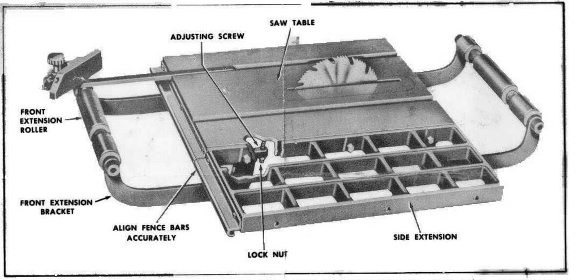
Fasten the Table Extension to the side of the saw table using the bolts, nuts and washers provided. The tables should be flush across their surfaces and at the ends. The two holes for attaching fence bar should be to the front of the saw.
- 2. Install the fence bar extension on the front edge of the table extension as shown. The bar must be carefully located to match the saw table fence bar so the fence will slide freely from one bar to the other.
- 3. The saw table and extension have been reinforced to support the weight of normal usage.
INSTRUCTIONS FOR ASSEMBLY OF ROLLER EXTENSION CAT. NO. 2356 TO BENCH SAWS, MODELS 103.23830, 103,23831, 113.1011, 113.22400, 113.22401, AND 103.23832
Your Roller Extension Set consists of:
1 ea.—roller 2'ea.—bracket attaching bolts 2 ea.—brackets 2 ea.—adjusting screws and lock nuts
The Extension Roller Set may be installed on both the front and rear of the 2383 Bench Saw, but only on the front of the 2240 model.
The brackets have been designed to accommodate the difference in the width of the tables on these saws (approx. 1 inch). If you look at the "roller-end" of the bracket you will see that the metal around the bearing hole extends farther on one side than on the other. As you look at the pair of brackets you will also note that they are opposites in this respect.
On the 2383 Bench Saw place the brackets so that this projection of metal is on the outside of the brackets. On the 2240 Bench Saw place the brackets so that this projection of metal is on the inside of the brackets.
1. Place the roller between the brackets as shown and attach the brackets to the table with the bolts provided. Do not tighten the attaching bolts securely until final adjustment has been made.
NOTE: When the roller is properly installed the undercuts will line up with both the table miter slots. Check by sliding the miter gage out over the roller as in the illustration.
2. Check each end of roller with a long straight edge to be sure that the roller is the same height as the table. Each bracket has an adjusting screw and locknut. This screw when turned against the lower table surface controls the height of the roller. Tighten the lock nut on each adjusting screw when the roller is set in the proper position.
3. Tighten the bracket attaching bolts securely.


 Loading...