


A CRAFTSMAN HANDBOOK
The ABC's of Electric Motors—How to Choose and Install Them
SEARS, ROEBUCK and CO. — U. S. A. SIMPSONS-SEARS, LIMITED—CANADA
MOTORS are Better than Muscles .
Yesterday, every household, farm and production task had to be done the hard way — by physical labor. Jobs like heating and refrigeration, sharpening tools, carpet sweeping, loading a silo — even the simple necessity of drawing water — all required muscles . and lots of your own energy, to get them done.
Today, silent, efficient dependable electric motors do all these chores — and hundreds more. Motors are used for just about every kind of work: Gar bage disposal, dishwashing, polishing — and heavy-duty labor and production jobs too numerous to mention. Count the electric motors serving you, You'll be surprised at the number.
IMPORTANT FEATURES
SPLIT-PHASE MOTORS
These motors are built for top economy and general use on easy-starting loads such as light power tools, office machines, small ventilating fans, etc. All are for 110-120 V, 60-cycle AC; are furnished with an 8-foot cord and plug.
STANDARD MODELS: Two sizes: 1/4 and 1/3 HP. Single-end shaft; precision bronze bearings. For use in horizontal positions only.
HEAVIER-DUTY MODEL: A 1/3 HP with superior (more than double) overload capacity. Double-end shaft; ball bearings. For use in any position.
CAPACITOR TYPE MOTORS
These are similar to split-phase motors but have capacitors added so that they will take medium-starting loads (approx. 50% heavier than split-phase motors of equal ratings), such as most home workshop tools, paint sprayers, refrigerators, stokers, etc.
ECONOMICAL APPLIANCE TYPE: Rugged 1/3 HP. Singleend shaft; precision bronze bearings. For 115 or 230 V, 60-cycle AC; horizontal position only.
POWERFUL SHOP TYPE: Sizes ½, ¾ and 1 HP. Double-end shaft; ball bearings; ON-OFF switch; thermal overload protector; cord and plug. Operate in any position. The 1 HP. has superior overload capacity — is for 115 or 230 V, 60-cycle AC. Others for 110-120 V, 60-cycle AC.
HEAVY-DUTY MILL TYPE: Sizes ½ to 1½ HP. Single-end keyway shaft; ball bearings; thermal overload protector. Operate in any position; superior overload capacity. For 115 or 230 V, 60-cycle AC.
but You Should Know How to Use Them

As wonderfully designed and miracle-working most motors are, there are limits to the size of d that each can carry — to the neglect and abuse that each can suffer without damage. You don't expect too much of your muscles. It's just as unreasonable to ask more of a motor than it is designed to give.
Before putting your new motor to work, do it and yourself — the favor of learning something about it. Read this booklet. It tells you how to judge whether or not you have the right motor for your job. It also tells you how to install and maintain your motor so that it will serve you faithfully and tirelessly.
OF SEARS MOTORS
Most Sears general-purpose motors are available for either clockwise or counterclockwise - rotation, as wired when purchased. However, all these general-purpose motors can easily be reversed by following simple directions furnished with each.
REPULSION-INDUCTION AND
The finest motors built, each is designed for beaviest starting loads and constant use, with great overload capacity.
R-I MOTOR: For single-phase, 115 or 230 V, 60-cycle AC. Sizes 1/3 to 5 HP. Single-end, keyway shaft; ball bearings. Excellent for farm and R.E.A. (Rural Electrification Administration) lines, low-voltage lines, and extreme weather conditions.
3-PHASE MOTOR: For 3-phase, 220 or 440 V, 60-cycle AC (usually, only in industrial areas). Sizes 1/2 to 5 HP. Single-end, keyway shaft; ball bearings. Provides the most economical operation of any type.
TOTALLY ENCLOSED MOTORS
These are special purpose capacitor type motors, externally fan cooled for continuous duty. Designed for medium-starting loads in dusty places. Ideal for high-speed power tool use, and the industry.
ON-OFF switch; thermal overload protector; cord and plug. Operate in any position. The ½ and ½ HP are for 110-120 V, 60-cycle AC; the 1 HP is for 115 or 230 V, 60-cycle AC.
Commercial electricity is manufactured by Power Company generators, and transported by wires in the form of current And there are different kinds DC (direct current) electricity is like a spinning wheel that revolves always in one direction; AC (alternating current) is like a pump handle that travels back and forth. Both currents travel at 186,000 miles per sec. - but AC can be made to change direction with varying rapidity (frequency). If it changes 120 times per sec. (so that it "goes out" and "returns to" the generator 60 times per sec.) we call it 60-cycle AC. Most AC is now 60-cycle, though 25- and 50-cycle are occasionally used.
ELECTRICAL TERMS USED IN DESCRIBING MOTORS Each TYPE of MOTCR
Motors can be classed in 3 major groups: Direct Current (DC), COMMUTATOR Alternating Current (AC), and Universal (AC: DC) - depending on the type current on which they will run. DIRECT-CURRENT MOTORS
The earliest kind, DC motors are still used for some purposes, and where only DC power is available.
In a simple, Series Wound DC motor, current "flows" through the wires of a field (stationary part) then through wires on an armature (rotating part). It is conducted to the armature by brushes which rub a commutator on the shaft. In "flowing" it makes the field and armature into magnets having north (N) poles and south (S) poles with like poles adjacent. But like poles repel each other - so the armature rotates 180° to place the unlike poles (which attract each other) adjacent. However, each time the armature rotates 180° the commutator reverses current flow through the armature so that adjacent poles are again alike. Hence the armature continues to rotate.
The above motor will vary in speed with variations in the voltage and the load placed on it, but is powerful at starting. There are also Shunt-Wound and Compound-Wound DC motors.
ALTERNATING-CURRENT MOTORS
AC motors are of 4 basic types, but for practical purposes we will consider only the Repulsion and Induction types. The other 2 are: Series-Wound (see Universal Motors), and Synchronous (used mostly for clocks)
REDITI STON MOTOR
This is like the Series-Wound DC motor - except that the brushes are connected together, instead of in series with the field. When the field is excited (current turned on), a current (and resulting N and S poles) is created in the armature by an electrical process called induction. Therefore, the motor will run without the the same as a Series-Wound DC motor. Consequently, it is limited in use — and Sears does not carry this type.

AC REPULSION TYPE

A circuit is an unbroken "path" from the generator to the device using electricity, and back to the generator. This path is formed by conductors (usually wires). The amount of current "flowing" in a conductor at any instant is measured in amperes (A or amps) like water is measured in gallons. The force that propels it is measured in volts (V) like water pressure is measured in ft-lbs. VxA= Watts (W), the unit for measuring electrical power delivered by a current. Power companies sell current by Kilowatt Hours, meaning the equivalent of so many hours of work at the rate of 1.000 W per hour.
In general: The power company supplies your premises by means of 2 or 3 wires. If you have 2
wires, chances are your supply is 115 (approx.) V, 60-cycle single-phase AC (meaning that all the current "marches" back and forth in the wires like a single file of troops). If there are 3 wires (especially in a city), you probably have a choice of 115 V or 230 V, 60-cycle, single-phase AC, depending upon which 2 wires you use. However, you may have 3-phase AC (usually at 230 V or 440 V, 60-cycle), meaning that there are 3 singlephase currents (like 3 files of troops marching back and forth, but each line changing direction 1/3 of a cycle after another). In this case you will use all 3 wires. There is also 2-phase AC, also requiring 3 wires.
indesigned for a purpose.
INDUCTION MOTOR
When the Repulsion motor (p. 4.) is running, a flux (magnetic field) is created by the field magnets which will induce the needed blarity (existence of N and S poles) in the rotating part, without he aid of brushes and a commutator. These parts can be omitted, and we have an Induction motor — and the armature is now called a rotor and the field is called a stator . Some rotors are wire wound; some ( squirrel-cage type ) simply have a series of copper bars embedded in a soft iron core, or are diecast aluminum.
The Induction motor has big advantages over other types: It will run practically without loss of speed due to current or load variations, up to the limit of capacity; and is very efficient. But it is not self-starting, so various starting devices are used:
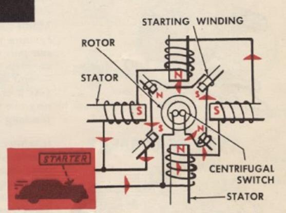
A SPLIT-PHASE motor is an induction motor with a starting winding added to the stator, and arranged to be cut out by a centrifugal switch after the motor is started.
A CAPACITOR motor is a Split-Phase motor with a condenser added to reduce the starting current required and increase the starting torque (power).
A SHADED-POLE motor is a variation of the Split-Phase motor, without means of cutting out the starting device. It has less starting power and is less efficient in operation.
A REPULSION-INDUCTION motor is a Repulsion motor with a centrifugal switch to cut out the brushes after starting. In some types the brushes are also lifted off the commutator. This motor has all the best features of both types, starting as a Repulsion motor but running as an Induction motor.
A 3-PHASE motor is "strictly" an Induction type. It uses 3phase current (top of page) and is like three separate, singlephase induction motors consolidated into one — with the added advantage that each exerts its "peak pull" during ½ of a cycle, while the other two are not at their "peak pull" positions. It has a very powerful start, and a great overload capacity — needs no starting devices.
UNIVERSAL MOTORS
These are really Series-Wound AC motors designed to perform vell on both single-phase AC and DC. Because they will develop destructively high speeds under no load, they are usually used as integral motors in hand power tools or for specific applications where they will be under constant, pre-determined load.
AC SPLIT-PHASE INDUCTION TYPE

CAPACITOR-START INDUCTION TYPE

3-PHASE INDUCTION TYPE
What to Consider WHEN SELECTING YOUR MOTOR

HORSEPOWER (HP)

TYPE OF CURRENT

AMPS – STARTING AND RUNNING

RPM AND DIRECTION OF ROTATION

RUNNING TIME AND TEMPERATURE RISE
If you are buying a motor to run new equipment, pay attention to the equipment manufacturer's recommendations. If you are replacing an old motor, learn the specifications of this old motor. In any case, always buy a motor equal to or better than called for — never one that has less power or inferior qualities. NOTE: If replacing a gasoline engine that has easily carried its load, you can generally use an AC motor rated at only 60-75% of the gas engine HP.
ELECTRICAL CHARACTERISTICS
The important electrical characteristics of a motor are printed on the motor nameplate, or are told to you in manufacturer's specifications (on which you can rely if the manufacturer is reliable).
If you push a car from a standing start on a level road, it takes an extra effort to start the car, then a smaller (but steady) effort to keep it rolling with occasional spurts of extra effort (again) as the car rolls over bumps. It's the same with a motor attached to a load. Therefore a motor is said to be capable of so much starting torque (push), so much running torque and so much overload torque . Breakdown torque (its maximum push, beyond which it stalls) is also used.
Motor torque is measured by horsepower, The rated HP of a motor is its running torque, at normal running speed. That is, a motor rated at 2 HP can pull with the strength of two horses — for all of its life. At starting, or when required to give an extra spurt of effort, it is said to be overloaded — and the safe overload capacity of a motor is usually stated as so many. (say 2 or 5) times the rated HP. But this overload capacity is only a tempe rary one because a motor heats up rapidly, and may burn out, if overloadea too long or too much.
It is very important to most motors whether you connect them to DC or AC, whether AC is single-, 2- or 3-phase — and whether the voltage is 115 or some other amount. Each is generally designed to run on a certain current with voltage of approximately a certain amount. Actually, there is a loss of voltage in power lines and Power Companies cannot always deliver exact voltages. Therefore, most motors are made to allow 10% voltage variation without harm; but the voltage should not be allowed to drop more than this (except that R-I and 3-Phase Motors can stand greater drops).
"Feeding" a motor a wrong current or wrong voltage will, at best, reduce its efficiency and life — at worst, can burn it up. It is particularly dangerous to an Induction motor to connect it to a DC line.
Just as you need a certain amount of food to keep going, so a motor needs a continuous supply of amps. And like you, when it works hardest, it needs an extra amount. Therefore, we say that a motor requires so many amps at starting (or for temporary overloads), and so many (generally only 1/3 to 1/4 of the starting amps) for normal running.
If you connect to the right power supply you needn't worry about having enough amps; but you do have to think about the size wires you use between the power source and your motor (wires that are too small can't carry enough amps). When choosing these wires, be sure to have them big enough to carry the starting amps, not just the running amps.
Induction-type motors run at practically constant speed (unless so overloaded as to stall) — and each is therefore rated according to the rpm (revolutions per minute) which its shaft will turn. The two commonest are approx. 1725 and 3450 rpm. You can, of course, obtain higher or lower speeds at the equipment by using various pulley sizes or gears; but it is often inconvenient to change an arrangement already planned for you by the manufacturer. Therefore, it's best to get a motor with the recommended rpm.
For the same reason, you can avoid trouble by getting a motor that revolves in the right direction (clockwise or counterclockwise). However, this is not too important with Sears motors as all can easily be reversed.
Though seldom indicated on a nameplate, you may have heard these terms. They refer to the "heating characteristics" of a motor. Every motor heats up as it runs ( temperature rise ). This rise is not critical unless a motor is overloaded too long — in which case it may overheat and burn out. Special purpose motors are sometimes built to run a while, then stop and cool a while — in which case running time is stated.
WHAT IS MEANT BY NEMA
N.E.M.A. means National Electrical Manufacturers' Association — the organization which coordinates the standardization of motor ratings and dimensions
PHYSICAL CHARACTERISTICS
The physical characteristics of a motor (its size, shape, etc.) can be just as important as its electrical characteristics, if it must fit a certain space or drive a specifically designed piece of equipment. Some of a motor's physical characteristics are listed in catalog specifications — others must be observed by looking at the motor, and perhaps by taking measurements.
SIZE AND SHAPE
Obviously, if you have limited space in which to install your motor, size and shape are very important. Not only must you consider whether or not the motor will fit in — it's also important for it to have room to "breathe" . All motors require a free circulation of air, to keep from overheating. Don't squeeze one into a space so tight that it will "suffocate" in its own heat!
TYPE AND SIZE OF BASE
ifferent motors are provided with different types of mounting arrangeents. Usually, you can adapt a motor to most any special mounting requirement (if there's room); but much time and trouble can be saved by getting a motor that will mount where you want it without alteration.
HEIGHT OF SHAFT
When considering the type of base, consider also the height at which the off sets above the base. If it is too high, you may have difficulty locating motor so that it can be connected to your equipment.
KIND OF SHAFT END
Motor shafts come in different sizes (1/2 in., 5/8 in., etc.) — and are of different types. For securing a pulley or tool to be driven by the motor, a shaft is generally slotted — for a key — or flattened (beveled) for use with set screws. Special shafts have detents (depressions for set screws), threads, holes (for pins), etc. If you don't have the right shaft, it's difficult to connect a motor to its load.
Some motors have a shaft at each end (instead of just one end) — which may be quite an advantage for certain purposes.
TYPE OF BEARINGS
The quality of the bearings used in a motor is not only important to the life and trouble-free running of the motor — it may also determine whether or not you can even use the motor. There are two general types of bearings: Ball bearings; and bronze (sleeve-type) bearings. Ball bearings are sealed in grease and, for most general purpose applications, may never need additional lubrication. Motors equipped with ball bearings may be mounted in any position. A bronze bearing motor, however, must be oiled — and should be mounted with the shaft horizontal, so that oil cups will be upright and will retain the oil.
THERMAL OVERLOAD PROTECTOR
When a motor becomes overloaded, it meets the increased demand for power by drawing a higher amperage. This can go on until it is overloaded to the point of stalling — and it will then draw an excessive amperage, so much (in fact) that either the motor or the wires to it will burn up if this condition is not corrected. A fuse in the circuit to the motor will correct this condition, by "blowing" to open the circuit.
Some motors, however, have a built-in thermal overload protector , which acts like a fuse to open the circuit, but is more convenient. Two kinds are used: 1) Automatic Reset (which closes the circuit again when motor has cooled sufficiently); and 2) Manual Reset (which can be closed by hand when the motor is cool enough).
SPECIAL HOUSINGS
e average motor housing is built to provide good protection for the otor (from dust and dirt) under normal conditions of motor operation around a home, office or plant. However, special conditions must sometimes be met — as when a motor must run in the presence of explosive fumes (around a gasoline depot). Housings designed for every conceivable special condition are available — but, remember, you must order them specifically.


PROPER WIRING PROCEDURES


WIRE COVER COLORS
Properly, the white covered wire is always neutral (grounded). Hot wire(s) are always some other color (black, or if its a 3-wire system, black and red, etc.).
SCREW-TYPE TERMINALS
If a motor has one white terminal (the other(s) being copper), connect the white-covered wire to this white terminal. To connect wires, whitle the insulation away at an angle to leave about 3/4-inch of clean, bare wire. If wire is No. 8 or smaller, connect it by forming a loop to turn with the screw , as shown. If it is No. 6 or larger, either solder it to the terminal or use a solderless terminal (of type shown) and connect this to the motor terminal.
SOLDERLESS SPLICES
Wires No. 8 and smaller can be spliced (joined), as shown, with solderless connectors — if wires will not be under any strain. If under strain, wires should be soldered together. No. 6 and larger wires should be joined with metal connectors (of types shown
SOLDERED SPLICES
Good soldering is essential for a permanent connection that will not offer resistance to the "flow" of the current. Clean wires thoroughly. Twist them together as shown. Then heat the wire (not the solder) while touching solder to wire. This assures filling all the cracks with solder stuck to the wires. (A solder dipper, illustrated, saves time). Tape the splice, overlapping the wire covers at least 1/4 inch, either with a double layer of plastic tape, or a layer of rubber tape topped with two layers of friction tape.
SELECTING WIRE
Typical wire types and their uses are illustrated. Consult your local code. Single (indoor) wire is cheapest to use, but most codes require this to be kept in the open (where it can be checked), or enclosed in metal conduit. Indoor cable is easier to install, and may be hidden inside walls. Entrance wire (from power lines into a building) usually must be in metal conduit. Some codes prohibit indoor wire (especially armored cable) in barns (where fumes deteriorate metal).
TYPES OF WIRE


STRINGING WIRE
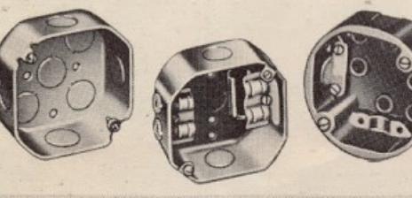
Always enclose splices (after taping) in outlet boxes. These are of various types — for hiding in a wall, or mounting in the open. When used only to enclose a splice, a plain box cover is used; but covers incorporating plug outlets, switches, etc. may be used. Some have built-in connectors (illustrated) to hold cable ends securely n the box. Others simply have knock-outs to provide holes, and separate connectors (illustrated) must be used to secure the cable ends. If single wire is used, the ends entering a box should be enclosed in looms.
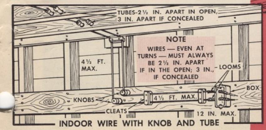
Codes require that cables or wires be supported. Typical requirements are illustrated. Cables may be strung through bored holes, but cannot be bent at sharp angles. Single wires are usually placed in tubes to pass through wood, etc. — and must be supported and properly spaced apart on porcelain cleats or knobs . Or they may be run through metal conduit . All wires or cables should be placed where they cannot suffer mechanical injury — should be protected (if necessary) by wood strips supported out from (not against) them.
Always mount switches and receptacles where they can conveniently be reached — without standing in water or on a damp or slippery surface. If exposed to weather, be sure to use approved outdoor types.
Sears Electrical Appliance Dept. offers a complete assortment of wires, accessories and electrical devices for every type of installation.
DOOR THE NNECTOR NOUIT NOTE NOT ENDOOR WIRE IN CONDUIT
NOTE
SAME AS FOR ARMORED
CABLE.
NON-METALLIC CABLE
USE STRAPS (NOT STAPLES)
Devices to AID YOUR INSTALLATION

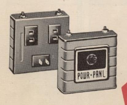
ENTRANCE SWITCHES
Both fused and fuseless types — sizes and circuit arrangements for every need. The fuseless types shown are fully magnetic (do not respond to heat or cold) with manual re-set buttons — will carry momentary overload caused by starting of a motor.
KER SWITCH

Safety switches (for convenient remote control of motor, etc.) are available with or without fuse sockets. Fuse cabinets (for separate fusing of motor circuit) are available with 2 to 8 circuits.


OUTLET BOXES
Steel boxes for flush or surface mounting and bakelite boxes for surface mounting. Covers with receptacles and switches of various types. Also outdoor boxes.


LOZE2
best motor protection as you needn't allow "oversize" to carry the starting load. Cartridge fuses (for main lines) and standard types also available.
REVERSING SWITCH
Compact switch for reversing any Split-Phase or Capacitor-Type motor up to 1 HP. Connection diagrams with switch.

A safe, convenient, 2-plug receptacle with toggle switch — for motors up to 1 HP total for the two receptacles.

HOW TO INSTALL YOUR MOTOR
ELECTRICAL REQUIREMENTS
USE LARGE ENOUGH WIRE, SWITCHES, ETC.
Importance of "Safe" Size
All wires and electrical devices (switches, receptacles, etc.) are designed to carry up to a specified load (no. of amps). Overloads may: 1) Cause wires or devices to burn out — with danger of fire; 2) Cause excessive voltage drop (loss of voltage at motor) so that motor runs inefficiently, overheats, and could burn out. Voltage drop should be held to 5% max. for R-I and 3-Phase motors; to 2% max. for all other motors.
'iguring Loads
For a motor, use the "Amps" shown on nameplate —and add 30% for safety. Other appliances are usually rated in watts . Amps = watts watts (i.e.: a 60
att bulb on a 115V circuit = 60 = 0.5+amps).
Selecting Devices and Wires
Devices are labeled in amps. Wires are rated by diameters with AWG (Am. Wire Gage) Nos.; by type (of covering); and by length. A wire may be just right to carry a certain load for (say) 50 ft; but not to carry it 100 ft. Reason: the longer a wire is the greater the voltage drop at its end.

|
Wire
Size (AWG) |
Armored or Non-
Metallic Cable — or Indoor Wire in Conduit |
Indoor Wire
(Knob & Tube) |
Outside
Wiring (p. 9) |
|
|---|---|---|---|---|
| ~ | 14 | 15 | 20 | 30 |
| E | 12 | 20 | 25 | 40 . |
| FI | 10 | 30 | 40 | 55 |
| W | 8 | 45 | 55 | 70 |
| S | 6 | 65 | 80 | 100 |
| - | 4 | 85 | 105 | 130 |
| E | 2 | 115 | 140 | 175 |
| AB | 1 | 130 | 165 | 205 |
| 4 | 0 | 150 | 195 | 235 |
Ratings in table are for 50 ft lengths of 2-wire cable or extension cord — or 100 ft of single wire. Increase wire by one size for each added 50 (or 100) ft, or fraction thereof. Never use smaller than 14 wire — or ordinary extension cord — for permanent wiring.

USE A SMALL ENOUGH FUSE
Every motor deserves the protection of an individual fuse or circuit breaker designed to "blow" before motor can be damaged. Because the starting amps required are much greater than the normal running amps , a standard fuse big enough not to blow every time motor starts is much too big to protect motor against burn out from continuous overloading. Therefore, only a Time-Lag fuse (p. 10) will protect your motor. Use one rated the same as the "Amps" on motor nameplate, plus not more than 25%. On 115/230V circuits, use 2 fuses; use 3 on a 3-phase circuit.
FUSES ARE CHEAPER THAN MOTORS!
MAKING CONNECTIONS AT MOTOR
Your Sears motor will have a cord and plug, or a conduit box with colored wire leads inside it. If there are leads, splice them (p. 8) to the circuit wires according to wiring diagram on motor.

CONNECTING TO AN EXISTING CIRCUIT
Before plugging-in or splicing a motor branch circuit to an existing circuit, check the wire (etc.) sizes — and check the load already on the circuit.
1. Some appliances will be OFF while others are ON. Just total the amps for those which could be ON simultaneously.
2. A 1/4 or 1/3 HP motor can generally be added to an average household circuit without overloading it — and a 1/2 or 3/4 HP motor probably can
if there are no other motors or heating appliances on the circuit. Larger motors usually require a separate circuit.
3. Open the circuit by removing the fuse (or fuses) which controls it.
4. If circuit has a standard fuse(s), substitute Time-Lag fuse(s), or install one in the separate line to motor — unless motor has built-in overload protection.

PROVIDING A NEW BRANCH CIRCUIT
A new branch circuit is one starting at your entrance switch — and may be installed if switch has provision for an additional circuit. Just remember:
1. If spare terminals are exposed and you can connect to entrance switch without disassembling it, simply open the switch to simultaneously shut off all house current. If you must disassemble switch or touch any wire leading into it, first have Power Co. shut off your service.
2. Complete the new wiring before connecting it to entrance switch.
3. Check to see that spare terminals in entrance switch are intended to carry load you will connect to them. Usually, fuse sizes are indicated on the switch cover — and you can tell from this.
4. If motor will operate on 115/230V, choose 230V whenever possible.


PROVIDING A NEW MAIN CIRCUIT
If the existing circuits and entrance switch are loaded to capacity — or if you need 230V and have only 115V — you will have to install a new service switch connected directly to the Power Co. lines.
1. Use any suitable size switch (p. 10) and mount this conveniently near the existing entrance switch. Complete all wiring from new switch to motor(s).
2. Have Power Co. connect new switch to their line — or have them shut off the power while you
make the connection.
3. If lines entering original switch are large enough (Power Co. will advise), you can connect new switch to these lines inside the original switch, as shown. Otherwise, you must provide new leadin wiring to a Service Entrance Head (or Yardpole, on a farm). Complete instructions are given in Sears' booklet "Electric Wiring for Home or Farm" on sale in our Elect. Appliances Dept. for a small sum.

SAFETY NOTES
Never work with existing wires or equipment without first making certain power is OFF.
Check local codes before buying wire or equipment — or doing any wiring.
Avoid long extension cords — they are subject to damage.
For wiring in barns (where dampness and manure fumes rapidly deteriorate ordinary wires and metal) we recommend use of our Single Wire
Trench Cable with Knob and Tube installation (p. 9), together with Bakelite Surface Wiring Devices (p. 10). Open wiring permits frequent inspection.
Never install devices where someone must stand in dampness or close to machinery to operate them.
In stringing long wires remember to support weight of wire properly — and allow slack to take up the contraction of wire in cold weather.
PHYSICAL MOUNTING REQUIREMENTS
PRE-MOUNTING CHECK
To check against shipping damage, rotate the shaft with your fingers — it should turn freely. Now operate the motor without load — it should run smoothly with a low electrical hum.
SELECTING LOCATION
Locate motor where it will be as dry and cool as possible. Do not expose it to weather, nor enclose it so that it doesn't get free air circulation. (Wire screens around a motor may become clogged and shut off circulation). Also, don't install it where possible sparks could ignite grain dust or similar inflammables — unless it is a special enclosed type.
MOUNTING
Bronze bearing motors should be mounted borizontally — to prevent the oil from draining out of the oil cups. Ball bearing motors may be mounted in any position.
If quiet operation is desired, motor may be mounted on rubber or spring cushions — but this will cause it to "float" and is not advisable when exact shaft alignment is required.
There are two methods of maintaining belt tension. 1) Use the motor base slots, and slide the motor to tighten the belt. 2) Use a motor rail as illustrated. In either case, make the retaining bolts secure.
MEASURING FOR V-BELTS
You can measure with string or tape around the outside edges ( not in the grooves) of the motor pulley and driven pulley — to obtain belt length. Length can also be figured as shown in accompanying illustration.


A belt should be just tight enough so that finger pressure midway between pulleys will deflect it about 1/4 inch. If too loose, slippage of the pulleys will wear it out. If too tight, it increases motor load and wear on the bearings.
SELECTING PULLEYS
V-pulleys are measured from edge to edge (not in groove). The following table gives you the speeds of driven pulleys when using various combinations of drive and driven pulley sizes (in inches).
* DRIVEN PULLEY SPEEDS IN RPM
| DIAM. | DIAMETER OF PULLEY ON MACHINE, INCHES | ||||||||||||||
|---|---|---|---|---|---|---|---|---|---|---|---|---|---|---|---|
| PULLEY | 11/4 | 11/2 | 13/4 | 2 | 21/4 | 21/2 | 3 | 4 | 5 | 61/2 | 8 | 10 | 12 | 15 | 18 |
| 11/4 | 1725 | 1435 | 1230 | 1075 | 950 | 850 | 715 | 540 | 430 | 330 | 265 | 215 | 175 | 140 | 115 |
| 11/2 | 2075 | 1725 | 1475 | 1290 | 1140 | 1030 | 850 | 645 | 515 | 395 | 320 | 265 | 215 | 170 | 140 |
| 13/4 | 2400 | 2000 | 1725 | 1500 | 1340 | 1200 | 1000 | 750 | 600 | 460 | 375 | 315 | 250 | 200 | 165 |
| 2 | 2775 | 2290 | 1970 | 1725 | 1530 | 1375 | 1145 | 850 | 685 | 530 | 430 | 345 | 285 | 230 | 190 |
| 21/4 | 3100 | 2580 | 2200 | 1930 | 1725 | 1550 | 1290 | 965 | 775 | 595 | 485 | 385 | 325 | 255 | 215 |
| 21/2 | 3450 | 2870 | 2460 | 2150 | 1900 | 1725 | 1435 | 1075 | 850 | 660 | 540 | 430 | 355 | 285 | 240 |
| 3 | 4140 | 3450 | 2950 | 2580 | 2290 | 2070 | 1725 | 1290 | 1070 | . 800 | 615 | 515 | 430 | 345 | 285 |
| 4 | 5500 | 4575 | 3950 | 3450 | 3060 | 2775 | 2295 | 1725 | 1375 | 1060 | 860 | 700 | 575 | 460 | 375 |
| 5 | 6850 | 5750 | 4920 | 4300 | 3825 | 3450 | 2865 | 2150 | 1725 | 1325 | 1075 | 860 | 715 | 575 | 475 |
| 61/2 | 8950 | 7475 | 6400 | 5600 | 4975 | 4480 | 3730 | 2790 | 2240 | 1725 | 1400 | 1120 | 930 | 745 | 620 |
| 8 | 9200 | 7870 | 6900 | 6125 | 5520 | 4600 | 3450 | 2750 | 2120 | 1725 | 1375 | 1140 | 915 | 765 | |
| 10 | 2 | 9850 | 8620 | 7670 | 6900 | 5750 | 4300 | 3450 | 2650 | 2150 | 1725 | 1430 | 1140 | 950 | |
| 12 | 24 | Selection. | 1 | 9200 | 8280 | 6900 | 5160 | 4130 | 3180 | 2580 | 2075 | 1725 | 1375 | 1140 | |
| 15 | 22/3 | 12759.2 | 8635 | 6470 | 5170 | 3970 | 3230 | 2580 | 2150 | 1725 | 1425 | ||||
| 18 | - 1. | 1. Starter | 7750 | 6200 | 4770 | 3880 | 3100 | 2580 | 2070 | 1725 | |||||
• DRIVEN pulley speed based on use of a 1,725 rpm motor. For a 3,450 rpm motor double the speeds listed. The formula for figuring speeds is:
Dia. of Drive Pulley Dia. of Driven Pulley = Speed of Machine Speed of Motor
PRECAUTIONS THAT WILL SAVE YOUR MOTOR
DON'T OVERLOAD MOTOR
Overloading a motor can burn it out. Don't expect it to run continuously overloaded.
DON'T LET VOLTAGE DROP
When voltage at motor drops, exactly the same thing happens as when the motor is overloaded. With too little "fuel" it is (in effect) overworked — heats up — and will burn out. Use ample size wiring.
DON'T "SUFFOCATE" MOTOR
If free circulation of air to a motor is restricted (by dirt, rags or paper, or closing it up in a box) it overheats — may burn out. Keep motor clean , and dry.
If used where wood chips, dust, etc. can enter inside, blow out the interior with dry compressed air — or use a vacuum cleaner.
GROUND MOTOR PROPERLY
The motor frame should be connected, by wire of same size used in line to motor, to a suitable ground (water pipes or a grounding rod properly installed) — both to protect you, and to protect the motor in case of an internal short circuit.
LUBRICATE MOTOR PROPERLY
Motors with bronze bearings do require regular — but not too frequent or excessive — lubrication. It's best to check often and add a few drops each time. Too much oil can cause trouble by getting out of the bearing into the motor.
USE RE-SET PROPERLY
If you have an overload protector with a manual reset button, always wait for motor to cool before using the re-set. Never hammer the re-set (if it seems to "stick"), as this will break off the switch parts. Any trouble with re-setting will probably be due to dust between the contacts — and blowing away the dust, or simply holding the button in firmly, will correct this.


 Loading...