

Sears | Craftsman How to Do More with your Jointer-Shaper- Disc and Belt Sander Instruction Guides
HOW TO DO MORE WITH YOUR Jointer-Shaper-Disc and Belt Sander
2916
OVER 150 OPERATIONS DESCRIBED AND ILLUSTRATED

CRAFTSMAN HANDBOOK

REVISED 1969
INDEX
THE JOINTER
GENERAL INFORMATION . 2-3 Advantages and Selections
SHOP-TESTED ACCESSORIES . 4
USING YOUR JOINTER ..... 5-11 Hand Positions – Surface Jointing – Edge Jointing – End Jointing – Squaring – Taper Jointing – Bevel Jointing – Rabbeting – Tenoning
THE SHAPER
GENERAL INFORMATION . 12-13 Advantages – Cutter Selection – Shop-Tested Accessories
PLANNING SHAPER OPERATIONS .....14 Planning Cuts – Rotation and Feeding
STRAIGHT-EDGE SHAPING . .15-17 Handling Various Workpieces
CURVED-EDGE SHAPING .....18 Use of Collars and Jigs
PATTERN SHAPING ....................................
SPECIAL SHAPING OPERATIONS ....................................
THE SANDER
GENERAL INFORMATION ....................................
The Jointer, Shaper and Belt and Disc Sander
An Illustrated Manual of Operation
for the...
HOME CRAFTSMAN SHOP OWNER
SELECTING YOUR POWER TOOLS SET-UPS AND ACCESSORIES PLANNING YOUR WORK ALL STANDARD AND SPECIAL OPERATIONS WITH YOUR TOOLS
OVER 200 ILLUSTRATIONS
A CRAFTSMAN HANDBOOK
A MIDWEST TECHNICAL PUBLICATION
Copyrighted 1969 SEARS, ROEBUCK and CO.
Catalog No. 9-2916
Form No. B71 738939 A000
Printed in U.S.A.
SEARS CRAFTSMAN JOINTERS-

ADVANTAGES OF A JOINTER
A jointer applies power to doing the same kind of work done with a hand plane. Not only will the jointer do the work much faster, it will also do it much better ... truer and smoother. Even an inexperienced worker can — with a Craftsman Jointer — soon learn to produce straight, true joints and planed surfaces, with hardly a visible space between the mated boards. This kind of jointing is extremely advantageous in fine cabinetmaking ... especially when working with rare and expensive woods which may have. to be pieced or veneered to obtain desired effects without waste and prohibitive cast.
SELECTING A JOINTER
Sears offers two different jointers, as illustrated . a 4-1/8-in. "homeshop" model for the homecraftsman, and a larger capacity 6-1/8in. "heavy-duty" model for the professional cabinetmaker. Capacity - expressed in inches - is the maximum width board that can be planed in one pass over the jointer knives.
Jointing and piecing call for planing the edges of boards. Since workpieces are normally no thicker than 2 in., practically any joint you will ever wish to make can be done on the smallest jointer. Surfacing — to reduce board thickness
or to level and smooth the surface for veneering or finishing — calls for planing across the width of a board. Boards of almost twice the width of the jointer capacity can be planed in two passes (each with a different edge against the fence) ... but to surface plane a still wider board a larger planer is needed.
THE PROPER MOTOR
Do not underpower your jointer ... nor fail to provide the recommended operating speed. Consistently smooth cutting is impossible if the jointer cannot operate, under load, at the required rpm. Always use a motor pulley of the size recommended ... and a motor with the rpm recommended and of a capacity to produce as much or more hp.
FOR BEST WORK WITH YOUR JOINTER
Typical jointer operating controls are shown in the illustrations. These controls and the several operating adjustments necessary are fully explained in the instruction sheet furnished with your jointer. For top quality work, learn your controls – and keep your tool lubricated and in perfect adjustment, as recommended. Also, always keep your cutter knives sharp ... dull knives will overload your motor and produce poor quality work.
-For Professionals or Hobbyists

4-1/8-IN. HOMESHOP JOINTER

SHOP-TESTED ACCESSORIES FOR SAFETY AND CONVENIENCE

work firmly down in contact with cutter.
delay while original set is being sharpened.

USING YOUR JOINTER
IMPORTANT
For the sake of clarity most of the following illustrations show the cutter guard removed. However, when using your jointer, never remove the guard unless absolutely necessary. It is there to protect you from possible injury.
IMPORTANCE OF ADJUSTMENTS
There are three very critical adjustments on any jointer: 1) Leveling of the tables; 2) Cutterhead alignment; and 3) Accurate alignment of the knives in the cutter head. The instruction sheet packaged with your jointer will tell you about these, and any other necessary adjustments. Keep your jointer in perfect adjustment at all times ... this is the only way to assure good work.
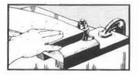
CORRECT HAND POSITIONS
In determining hand positions, two things must be kept in mind: 1) The fingers must not be allowed to pass dangerously close to the revolving knives; 2) The work must be kept in solid contact with both table tops, if a straight true cut is to be made. In general, there are three methods of accomplishing this.

First, and best for edge jointing, is the "follow through" method. The hands are placed on top of the work so that the left hand will be above the front edge of the rear table just as soon as enough of the work has passed over the jointer knives – and is used to press the work firmly down on the rear table to obtain a true cut. As the work progresses, the left hand is moved backward along the work so that it will remain approximately above the front edge of the rear table. The right hand is placed on the front edge of the work where it can be used to simultaneously hold the work down on the front table and to push the work forward across the
knives. It remains in this position on the work until the cut is completed — and therefore passes directly over the knives as the back end of the work is finished. When using the hands thus, care must be taken to pull the thumb up ward to a safe height above the knives as the right hand passes over the cutter hast

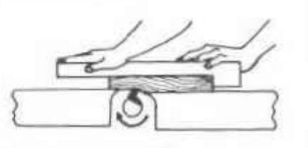
The second method is best when surfacing boards, and does not require either hand to pass over the knives. At the start, both hands are kept on top of that part of the work which rests on the front table. When enough of the work has passed onto the rear table, the left hand is lifted up and moved through the air to rest on top of the portion of the work now on the rear table. Similarly, as the back edge of the work approaches the cutter head, the right hand is also lifted and moved to the rear table. As in the case of the first method, the left hand is used entirely to hold the work firmly down while the right hand is used both for holding the work down and for propeiling it over the knives.

The third method requires use of the holddown attachment – and is certainly the safest for surfacing thin ard/or narrow boards. Mount the hold-down on an auxiliary board (fence)
that can be clamped to the jointer fence ... then adjust it to hold the work down on both tables and up against the fence. Do not use your hands; push the work through with the end of a scrap board or a push stick.

Special hand holds are required when jointing the edge of a very wide board, or when jointing the end of a board which will project twelve or more inches upward from the table. Obviously, support must be given to the board to keep it from rocking to the right or left – and the laft hand is therefore used principally to push the board over against the fence to keep it squarely upright. If the board extends high enough above the table, the weight of the board will hold it down, and the right hand can be used to propel it over the knives; otherwise, the right hand should be on top of the board to both hold it down and propel it.
MAKING A CUT

Unless a special operation requires otherwise, always cut with the grain of the wood – as illustrated. If necessary to cut against the grain, move the workpiece at about one-half normal speed across the cutter head, and slow down even more when approaching the end of the workpiece. This will prevent the knives from splitting the end of the workpiece.
Edge or rabbet cuts up to 1/2-inch deep can be made — but best results are obtained with maximum cuts of 1/8 to 3/16-inch deep, and by making successive cuts to obtain greater depths. When it is necessary to make a single deep cut, feed the work at a slower rate than normal to keep from slowing down the cutter head. If the cutter head slows down too much, the cut will be very rough.
SURFACE JOINTING
General Set-Up
Adjust the front table so that about a 1/32-inch cut will be made. The depth of cut can be estimated by sighting the difference between the levels of the two tables.
Set the fence at a right angle to the surfaces of the two tables. Generally speaking, the procedure now involves nothing more than pushing the work across the cutter head, using the hands as already explained. Before doing this, however, survey the work carefully to note whether it has either warp and/or wind. If it has, proceed as follows:
Boards with Warp and/or Wind

Warped lumber is dished from side to side across the board. Such workpieces are preferably surfaced on the dished or concave side, as the two edges of the board will rest on the table top to keep the board from rocking. Whenever it is necessary to surface the convex side of such a workpiece, always hold the work firmly to prevent its rocking while passing over the cutter head. In either case, make a sufficient number of passes over the cutter head to reduce the work to a flat surface.

Wind is a twisting of the workpiece from end to end. Testing for wind can be done by sighting – or by rocking the board on a flat surface. When a workpiece is to be surfaced out of wind it is advisable to mark the work carefully to permit surfacing with the least number of cuts. This will avoid loss of workpiece thickness. After marking, support the workpiece so as to first
remove material only at the part where the most material must be removed - and in successive passes enlarge the area of cut until it finally takes in the entire underside of the workpiece.
When it is necessary to hold one edge or one corner of the workpiece up off the table top in order to remove wood from a low corner or edge to correct wind, use small blocks or strips of wood. Glue these to the high spots to hold board up level — so that bottom surface will be flat when they have bren completely whittled many the operation.
Thin Boards

A pusher shoe which will help you to both propel the work across the cutter and to hold the work down, is very handy for surfacing operations. Such a shoe is desirable for very thin boards. A design for a simple homemade

pusher shoe is illustrated. The small block projects down below the bottom surface of the larger block just enough so that it can be hooked behind the end of the workpiece to push it forward. It should not project down far enough to contact the cutter knives when the shoe is pushing the end of the work over the cutter head. The shoe should be long enough to firmly press the work down on the tables, from end to end.
The top of a very thin board may be lower than

the bottom edge of the fence adjacent to the rear table, so that the fence will not serve as a proper guide. This makes it necessary to use an auxiliary fence when surfacing such thin boards — as illustrated.
Wide Boards
Boards up to twice the width of the cutter head, less approximately 1/4-inch allowance for overlap, can be surfaced on your jointer. Simply make two passes of the board over the cutter head, without changing the height of the front table. The first cut will surface one-half of the board; turn the board completely around to surface the other half. One or the other of the two cuts must necessarily be made against the grain of the wood. Do the first cut in this manner, leaving the "against the grain" cut, feed the workpiece at approximately one-half the normal speed, and feed extremely slowly at the very end of the cut.
Long Boards
Very long boards create a problem because it is difficult to simultaneously handle the unwieldy board, and to press it down properly against the table tops. The hold-down attachment fastened to an auxiliary fence, is a great help. A homemade wood spring – or a simple wood block – clamped to the fence, can also be used.
Very Short Boards
WARNING: Don't endanger your hands. Always use a pusher shoe to propel thin and/or short boards.
Generally speaking, it is not practical to surface boards under 12 inches in length, because shorter boards do not provide sufficient handhold leverage to offset the kickback of the cutter head. A longer board – or, preferably, the pusher shoe (see illus, page 7) – must be placed on top of a short workpiece to propel it over the cutter head.
EDGE JOINTING
General Information
This is the simplest and most common operation to be done on the jointer. In general, approximately 1/8 inch of material should be the maximum removed in any one pass of the workpiece over the cutter head. Set the fence very carefully at a right angle to the table top. The workpiece is held and fed across the cutter head as already explained.
Fairly rough edges can be successfully jointed – but it is usually quicker and easier to cut off extremely rough edges on a band or bench saw, prior to jointing.
Dished and Bowed Edges

Dished (concave) edges present no great difficulty, if the whole length of the board extends out beyond the front of the front table; however, an auxiliary support (as shown) must be provided to hold this end up at exactly the same level with the end of the table.

Jointing the bowed (convex) edge of a board is
difficult because there is a tendency for the board to rock end-to-end. This cannot be overcome without the aid of some type of support. The best practice is to clamp two short pieces of scrap stock to the board, one at each end, so that the board will pass over the cutter head on a level plane. If the board is too long for the front block to rest on the table top at the start of the cut, use an auxiliary table.
Wide Boards

The low fence provided with your jointer is not high enough to properly support very wide boards, when edge jointing – and there is a tendency for the board to wobble from side to side during the operation. For this reason, it is advisable to attach an auxiliary fence to the regular fence – and to have this auxiliary fence high enough so that the workpiece can be pressed firmly against it to prevent wobble.
Very Rough Edges
A very rough edge can be successfully jointed if you remember to put all of the "down pressure" on that portion of the workpiece which is above the rear table. Do not put any "down pressure" on the end of the work which is on the front table, and which still has an uneven bottom edge.

End jointing is much the same as edge jointing; except that there is a tendency for the wood to
split at the back end as this end is passed over the cutter head. For this reason, two cuts — one from each edge of the board — are generally better than one straight cut. Make the first cut long enough to carry past the second or third grain of the wood at one edge. Turn the board around and make the second cut to overlap the first and give a straight edge. Do not make the first cut too long. A long enough edge must be left to keep the board steady on the top of rear table while finishing the second cut.
Dished and bowed ends are handled in the same minner as dished and bowed edges. When the board is very long (therefore standing high in the air above the table) it is advisable to provide some means of supporting it without its wobbling. Support can sometimes be provided by a horizontal board clamped to the workpiece and arranged to ride along an auxiliary support placed at the right side of the jointer.
SQUARING A BOARD
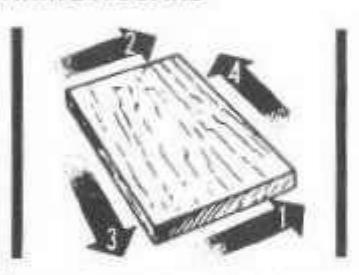
The first step in squaring all six sides of a board is to surface one side (preferably the side which is easiest to surface) in order to obtain a "working face." The two ends are then jointed; and afterwards the two edges are jointed. End and edge jointing are done with the working face pressed against the fence so that these joints will be square with the working face. The unquence of end and edge jointing steps is shown in the accompanying illustration.
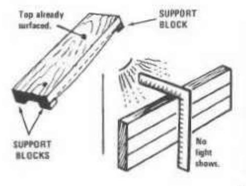
After jointing the ends and edges, proceed to surface the remaining face as follows: Cut four small wood blocks of equal length, and glue these to the edges of the board near the four corners in such manner that they will support the board with the working face on top and parallel with the front table of the jointer. These blocks should be just long enough to accomplish this perpose, and should not extend downward below the level of the lowest point on the unsurfaced side of the board. Now surface the underside of the board, making as many cuts as necessary to reduce it to an absolutely senonth surface.
To test a board for squareness, use a good square, as illustrated. The square should contact the faces of the board at all points, so that no light can shine through.
TAPER JOINTING

Taper jointing is very useful in making table legs like those illustrated, and for numerous other cabinetmaking operations.
Straight Tapers

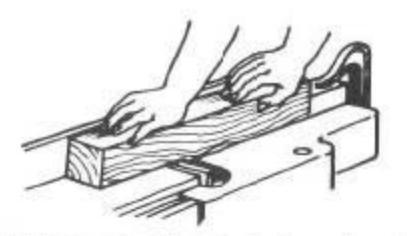
The simplest tapering operation is done with workpieces shorter in length than the front table. Set up as follows: Lower the front table to make approximately a 1/8-inch cut. Place the workpiece on top of the front table and against the fence – with the back edge barely resting on the edge of the rear table adjacent to the cutter head. With the workpiece in this position, clamp a piece of scrap wood to the front table so that it will butt up against the end of the workpiece.
After the set-up is made, remove the workpiece and start the jointer. Now place the end of the
workpiece against the block clamped to the front table (as it was during the set-up), and lower the other end onto the cutter head until portion just behind the cutter head (which will be uncut) rests on the rear table (as in the setup). Starting thus, advance the work across the cutter head. The uncut portion which was resting on the rear table at the start will hold this end high, so that the resulting cut will be tapered toward the other end of the workpiece. Continue lowering the front table approximately 1/8 inch at a time and making additional cuts in this same manner until the narrow end of the taper is as deep into the workpiece
If the workpiece is longer than the length of the front table, exactly the same procedure can be used — but an auxiliary extension must be fastened to the front table so that the entire workpiece will have a level surface to rest upon. If the front table is to be lowered for additional cuts, this extension must be lowered also.
A 2-SECTION TAPER
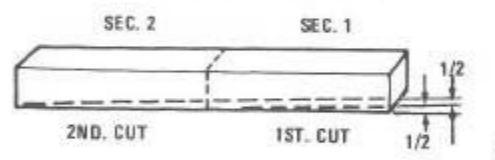
However, a long taper can be cut without an extension. Lay out the taper and divide the area to be tapered into sections, each section several inches shorter than the length of the front table. Start first cut at the section line nearest the tapered end of the workpiece. This first cut must remove 1/2 or 1/3, etc. idepending upon number of sections) of the total amount of stock to be removed from this workpiece end. Start second cut at second section line ... and again remove 1/2 or 1/3, etc. of total to be removed. Start third cut at third setion line ... etc.
Compound Tapering
A compound taper is made when a second

taper, at a greater angle than the original taper, is cut at one end of a tapered workpiece. Compound tapers can include two, three or more tapers – each at a greater angle than the adjoining taper.
To cut a compound taper, cut the first taper as already explained – then make a new set-up with the stop block arranged so that the workpiece will drop down onto the cutter edge at the point selected for starting the second taper. The second taper can then be cut in exactly the same manner in which the original taper was cut.

A stopped taper is one which does not run all the way to the end of the workpiece. This type of cut is often used in making table legs.
A stopped taper can be freehand cut by using the same procedure as for cutting straight tapers. It is only necessary to start and stop the cut at the proper places. However, the best practice is to lay out your plan for the taper on the workpiece, as illustrated. The starting line (A) should be directly above the highest point of the cutter head (approximately one inch to the front of the rear table front edge) at the start. The stopping line (B) should be approximately above the back edge of the front table at the end of the cut – and the workpiece must be lifted straight up off the cutter head when this point is reached.
It will be easier to handle the workpiece if the fence is moved as close to the left edge of the machine as the width of the workpiece will
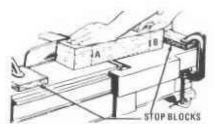
permit. If it is necessary to watch the guide lines, the cutter guard must either be removed or must be tied back out of the way. Stop blocks, clamped to the front and rear tables as illustrated, will make it easy to cut uniform stopped tapers on all four sides of one or more workpieces. Arrange the blocks so that the workpiece will butt against the one on the front table when the starting line (A) is correctly positioned for the start of the cut – and so that the stop block on the rear table will be bumped by the workpiece, when the finish line (B) is correctly positioned for the end of the cut
BEVEL JOINTING
Bevel jointing is done by tilting the fence to the desired angle, as indicated by the fence angle pointer and protractor scale. The fence can be tilted either in or out; but the latter is rasier. Once the fence has been set to the desired angle, the operation is like edge jointing.
Chamfering is done in the same manner; but only a small portion of the edge is removed. Taper cutting also can be done with the fence tilted, to produce a beveled taper.

Rabbets — or edge grooves — are easily cut on your jointer. Move the fence over to the outer edge of the jointer so that you will obtain the desired width of cut when the workpiece is pressed against the fence. Now make the cut in the same manner used for surfacing. As many cuts as necessary to obtain the desired depth of cut can be made. Also, successive cuts can be made with different fence settings to obtain stepped rabbets.
Beveled rabbets and tapered rabbets can also be cut by combining the technique for rabbeting with the set-ups used for bevel and/or taper
jointing. When cutting rabbets in very thin stock, be sure to use a pusher shoe as previously explained.
CUTTING ROUND TENONS

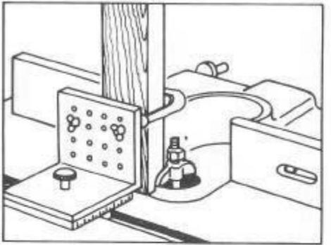
A round tenon at the end of a round workpiece can be cut in much the same menner as a rabbet. Use a stop block (as illustrated) to set the depth of cut _______, and, also, to extend across the front table in front of the workpiece, to hold it on top of the cutter head. Start the jointer and lower the workpiece onto the cutter head, then slowly revolve the workpiece _______ pressing it against the stop block _______ time a clockwise direction.
The same technique can be used to cut a round tenon at the end of a square workpiece, if a round ring of metal or wood is placed around it to provide a surface on which the workpiece can be revolved.
TAPERING IN THE ROUND
Round tapers can be made by making a series of straight tapers to reduce the workpiece to an octagon shape. The octagon workpiece is than mounted in a fixture to be simultaneously tapered and reduced to a neerly round shape. It is finished by sanding.

In ose, the guide black is presed against the fence – and successive cuts are made, turning the workpiece approximately 100 to 150 for each new cut. Many shapes are easily made by combining tapering in the round with straight and bevel tapering operations.
CRAFTSMAN WOOD SHAPER -----

HOLD-DOWN FINGER -
CONTROL LEVER -
.......................................
A MITER GAUGE
F

A must for shaping ends of boards too narrow to firmly contact both fence faces. Gauge should be fitted with the hold-down attachment so work can be fed without creeping and spoiling of cut.
A UNIVERSAL JIG

Another must for end shaping when board – especially a long and/or narrow one – is fed in vertical position. Also useful for edge shaping on-edge boards ... and for holding small or odd-shaped pieces.

SAFETY GOGGLES
There are many models of face shields and goggles. Never use your shaper without wearing the type that you prefer to safeguard your eyes.

-With SHOP-TESTED ACCESSORIES
PROFESSIONAL-QUALITY EDGE FINISHING REQUIRES A SHAPER
Especially designed for this single purpose, your Calitamin Shaper can be quickly and easily set up for a larger variety of shaping operations then are possible with any other tool. With it, you can shape into the edge or end of a board ... or into the board face along the edge or an inch or two up from the edge (since the spindle can be adjusted vertically). Depth of cut can be precisely controlled by the use of the collars and/ or by the set up of the two fence faces (independently adjustable). In addition to the many single-cutter shapes, you can create other shapes ... by raising or lowering the spindle ... or by overlapping and combining single cuts,
A REVERSING SWITCH
Easy operating switch hus center "OFF" with left and right positions for clockwise and counterclockwise operations. Easily mounted for convenient spindle control.
A WORK LIGHT (See page 4)
THE CORRECT MOTOR
Never underpower your shaper. A 1/2 hp. 3450 rpm motor is required ... to provide ample power and smooth-cutting speed. Choose the Craftsman motor that is recommended.
BANK A STEADY TOOL BASE
For maximum safety, convenience and accurate shaping your shaper must be firmly mounted. The base shown is designed for this purpose ... yet is easy to move around.

Telescoping shaper collars provide for varying depth of cut of any cutter to alter design. Three blade, high-speed cutters are evailable in the popular types illustrated for molding edge designs and/or preparing special points. The sash-door cutter comes in a kit with five special collars and two special nuts fiver page 200. There is also a 6-piece cutter set (9-32906) that includes nos. 3284, 3291, 3285, 3290, 3289 and 3294, above.

PLANNING A SHAPER OPERATION
BE PROPERLY PREPARED
The instruction sheet packaged with your Craftsman shaper describes the operating controls and their uses ... and also the few adjustments required for a set-up and for precision work. Learn how to operate and maintain your tool properly. Also, keep your cutters clean and sharp. These precautions will assure you the high-quality work for which your shaper is designed.
PLANNING SPECIAL CUTS

Make a cardboard cutout for each cutter, shaping the cardboard edges to the shape of one cutter blade. A file of such cutouts will make it easy to plan special shapes for molding. To obtain any special shape desired, simply trace the outlines of the selected cutouts onto the end (or edge) of your workpiece, as illustrated.

The planned cuts can be made one at a time ... or, in some cases, you can mount two cutters on the spindle (with or without a collar between) to accomplish two cuts simultaneously.
PLANNING CUTTER ROTATION AND FEED
Each blade on a cutter has a beveled outer (cutting) end . and the cutter must rotate so that the sharp (acute angle) edge of this bevel strikes the work. We say that a cutter is rightside-up when these sharp edges are at the left sides of the blades. Since your shaper spindle normally revolves clockwise, right-side-up is the normal way to mount a cutter on the spindle. If, however, you reverse the motor so that the spindle revolves counterclockwise, then the cutter must be mounted upside-down. Reversing spindle rotation and cutter mountings in-+ creases the variety of cuts you can obtain, and also makes some operations easier and safer (if cutting can be done all on the underside of the edge of a narrow board, instead of on the top edge where the cutter is exposed to your hands).

RIGHT-SIDE-UP ROTATION AND FEED

UPSIDE-DOWN ROTATION AND FEED
Work must always be fed against the rotation of the cutter. If spindle revolves clockwise (cutter right-side-up), feed from left to right; if spindle revolves counterclockwise (cutter upsidedown), feed from right to left.

STRAIGHT-EDGE SHAPING
USE OF THE SHAPER FENCE

Straight shaping can be done along the edge of a board laid flat on the table . or, if bourd is held on edge, into the face of the board along the edge or as high up as the cutter can be positioned. Your be . Juide for most such edge or face shaping operations is your shaper fence. The whole funce can be located at several different back-or forward positions, and each fence face can be moved back or forth and in and out . . so that the fence can be positioned to provide for any desired depth of cut with any one of the cutters. Moreover, the holddown, hold-in fingers can land always should? be used, as shown, to hold work firmly against the cutter.
SETTING UP FOR A CUT

The fence face on the side from which work is fed is called the loading face , and the trailing face is the one that guides the work after it has passed by the cutter. If only a portion of the workpiece edge against the fence is to be removed, set the leading and trailing faces parallel ... but if all of this edge will be removed, set
the trailing face far enough out in front of the leading face to compensate for the depth of the cut. All face shaping and most edge molding operations require removal of only part of the workpiece edge. Some edge shaping (like planning) does, however, require removal of all of the edge.

After mounting cutter(s) on spindle, place workpiece against the lending fence face with cutter blade(s) standing out across end of work, as shown. Adjust this leading face forward or back and also adjust the spindle up or down until blade outline(s) against work will match the pattern you've traced on this end (or until cut appears as you wish it). Afterwards, adjust the trailing fence face. If faces are to be parallel, use a straightedge to make them so. If trailing face is to be farther out, measure the depth of cut to be made on the end of the workpiece, and set the face accordingly.
Adways double check the fence face settings. To avoid spoiling a cut, the workpiece must slide smoothly along both faces in a perfectly straight line. If in doubt, make a trial cut on a piece of same thickness scrap.
NOTE
Collars should not normally be used as guides when using the fence. If used as spacers, be sure to use ones small enough in diameter not to project out as far its the fence leading face.
CUTTING WITH OR AGAINST THE GRAIN
Due to high speed of cutter rotation it makes

little difference with most woods whether your feed is with or against the wood grain. Some very lightweight, soft woods (like Redwood) may, however, splinter if fed against the grain. To avoid splintering try to plan feeding with the grain . or, if you can't, take very shallow cuts, making as many passes as necessary to reach final desired depth.
cutter with your hand(s). To be safe, if work is under 3 in. wide, finish the last 6 or more inches of shaping by propelling the work with a push stick of some kind. If work is thick enough, you can reverse the cutter and mold the under edge (as previously told)... and this may place your hand(s) a safe distance above the cutter.
END MOLDING

When molding all around a workpiece with angled corners, always cut across the end grain first so that the later with-grain cuts will eliminate any splinter gaps left by the crossgrain cuts. Methods of planning cuts are shown.
CUTTING ROUNDED CORNERS

When molding around a straight-sided workpiece with rounded corners, it is necessary to use a collar as well as the fence. Without a collar, the corner of the workpiece will recess between the fence faces as you turn the corner – and too deep a cut will result. Collar diameter must be such that the front side of the collar is exactly in line with the leading fence face ... so that while you are molding a straight side of the workp ece, this straight edge will simultaneously contact the leading face and the collar. If all cf an edge is being removed, you cannot use a collar, unless you also use a pattern (as explained later).
HANDLING NARROW WORK
Never push very narrow and thin work past a

To be properly guided by the fence, the workpiece edge against the fence must be long enough to rest firmly against both fence faces, simultaneously (overlapping each at least 2 inches) when half through the cut. Any attempt to use the fence for end molding of a toonarrow board will certainly result in a spoiled cut... and can result in a dangerous kickback if work slips into the cutter. Such an end can be molded with a collar, but the easiest, quickest way is to use a miter gauge.
Before using the miter gauge, adjust the leading fence face (as already explained) to set the depth of cut. Now set the trailing fence face back in from the leading face (instead of parallel or forward), so work will not contact it after passing the cutter. Next, place the work on the miter gauge with the end to be molded against the leading fence face. If you have a miter-gauge hold-down (which is preferable) clamp the work thus ... then simply feed it by pushing the gauge. If you don't have a holddown, you will either have to use the stop rods ... or you will have to hold it very securely against the gauge as you feed.
HANDLING SHORT WORK

If a workpiece is too small to be guided by the fence, or to be held by a miter gauge, you will have to use a homemade wooden guide, as illustrated.
ON-END SHAPING
This is the same as face shaping, except that it is done at the end of a long board which must be supported vertically. If board is not too unwieldy you can use the fence as a guide (using the hold-in finger to help hold it).
The best guide for such a purpose is the universal jig - to which board can be securely clamped. Make the set-up the same as for the miter gauge (preceding), then simply propel the jig in the miter-gauge table groove to feed the work.
Usually, however, this is not practical

Another device for guiding a long, on-end board is an extra high homemade wooden fence clamped to the table in place of the shaper fence. If also made extra long, the same fence can be used to support very long boards for on-edge shaping if only part of the edge is to be removed.

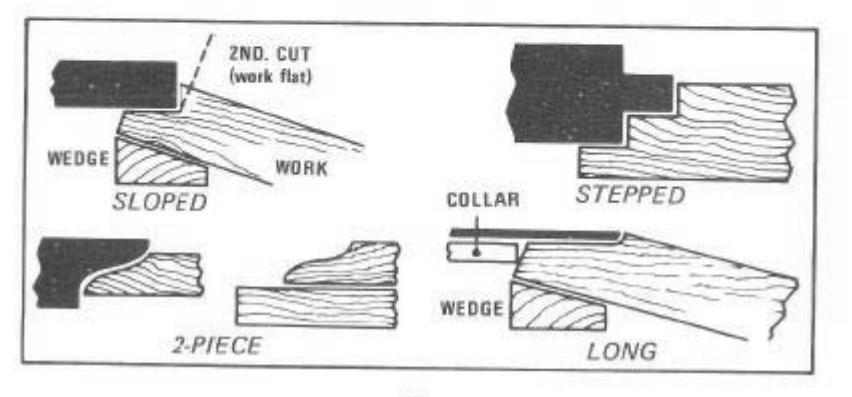
BEVEL-EDGE SHAPING


Whenever the workpiece is not too wide nor the bevel angle too acute, the quickest and simplest method of supporting the workpiece at the desired angle to the table is to (temporarily) nail a proper-shape wedge support to the underside of the workpiece. This support should be the same length as the workpiece. Another method is to build a bevel fence (like the one shown here) for the specific bevel angle desired ... or a variable-angle fence (see page 25). Still a third method is described later (see page 20).
FOR MORE AND BETTER OPERATIONS ALWAYS USE SEARS SHOP-TESTED ACCESSORIES

CURVED-EDGE SHAPING
USE OF COLLARS
COLLAR
Any convex-curved edge and any concavecurved edge that is not too tight for cutter to work into it can be shaped by using a collar (or collars) . providing that only part ( not all) of the edge is to be removed. Part of the edge must be left to ride against the collar(s). Collar(s) can be mounted below, above or between two cutters . and must be of a diameter(s) to contact the uncut workpiece edge when cutter is biting in to desired depth of cut.
Collars must be kept clean by washing them with kerosene and a stiff brush, to remove wood gum deposited on them. Also, the edge of the work to be pressed against a collar must be smooth and regular in contour as all irregularities will be duplicated by the cutter. In addition, the remaining part that will press against the collar must not be too thin or it may crumble.
USE OF THE GUIDE POST

The shaper fence is not used when using collars to shape curved edges. If you are going to shape continuously all around the workpiece, lack of a guide is no problem; simply push the workpiece straight into the cutter (from front towards rear of table) until the edge is against the collar(s) ... then feed the edge all around (while maintaining firm contact with the collar) until it is finished.
When, however, the cut must be started right at

an end – and cannot be overlapped at the finish – it is necessary to feed the workpiece to, rather than push it straight into, the cutter. If end is fed in at too shallow an angle, the starting cut won't be deep enough; and if it is fed in at too deep an angle, the end may be kicked back and splintered. To properly guide the work, use the guide post (furnished with shaper), as shown . swinging the work free of the post after the cut is started.

USE OF CIRCLE JIGS

Several types of homemade jigs for edging and face shaping circular work are shown. These can be clamped to the table, or can be bolted down with the shaper fence bolts.
PATTERN SHAPING
PLANNING A PATTERN

A pattern is a piece shaped to the exact contour desired for the finished workpiece. It can be made of wood, hardboard, plastic, etc. — but must be thick enough to provide a solid edge for riding against a collar. In addition, the pattern edge must be recessed (with respect to workpiece edge) enough to allow the workpiece edge to project into the cutter as desired, when the pattern edge is up against the collar. For this reason a pattern is usually a slightly smaller replica of the workpiece.

A pattern and the workpiece must be held firmly together throughout the operation. This can be accomplished by rubber-cementing them together, or by embedding brads in the pattern to leave only their points protruding to serve as anchor points for the workpiece. Or, if work and pattern are large enough to extend forward over the table, they can be clamped together, instead.
The pattern need not cover the entire workpiece. It is necessary only that it serve as a guide for the workpiece edge(s) to be shaped. For instance, if the two workpiece ends are to be identically shaped, a pattern for one (only) end can be moved to serve the other end. Or a pattern can be pieced together to create a desired outline.
USING A PATTERN

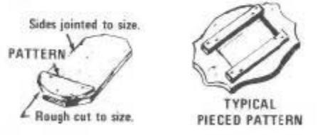
The workpiece must be preshaped to the desired contour. If all of its edge is to be shaped, this edge can be simply rough-cut (as shaping will eliminate irregularities)... but if it is to be only partly shaped, the edge must be cut smoothly and exactly. Feed the pattern and work to the cutter in the same manner described for shaping with a collar.
USE OF DOUBLE PATTERNS

Two identical patterns, with workpiece sandwiched between, can sometimes be used to advantage. This way – if the cutter is symetrical – the work can be flopped over, instead of being rotated 1800, to do the opposite edge (which will permit cutting both sides with the grain). Also, with some shapes you can hand hold such a set-up together, without anchor points, etc.

SPECIAL SHAPING OPERATIONS
SASH AND DOOR SHAPING

The Sash-and-Door Kit (page 13) , fully illustrated above, is designed for all operations needed to mold sash and door stiles and rails ... except that you will also need the 1/4-In, and 1/2-In. Groove Cutters. With this kit you can handle stock of standard 1-3/8-in, thickness or of varying commercial thicknesses.
The various cuts required are illustrated below. Figures A and B show the two operations needed to shape a door stile (for cut B the 1/4-in, groove cutter is used with the sash cutter, as shown). Figure C shows the first cut in shaping the matching door stile sash; and the second cut is an identical one made with the work flopped over. Figure D shows use of the sash cutter, a collar and the 1/2 in, groove cutter for shaping a window-sash stile. And figure E shows the second operation needed to complete a window-sash rail end (the first operation being the rabbet at top, made with a groove cutter).
BEVEL-EDGE SHAPING WITH A DOUBLE PATTERN
By using a double pattern as already described

(page 17) you can establish a wide enough edge to be held firmly against the shaper fence or a pair of collars while shaping a beveled edge. Preferably use the fence (rather than collars) for all straight edges ... and have the two pattern pieces thick enough to make the total assembly at least 2 inches thick where it touches the fence. Use the collars, instead, for all curved edges ... and also space the collars to contact these pattern pieces as near the too and bottom (respectively) as possible.

When feeding the work to the cuttur, hold the outer edge up, as shown. If, after completing a first pass, you find that your angle of holding was wrong, you can make a second pass for as many more as needed) to correct the cut ... the two patterns won't allow you to over-cut in any way so long its work edge at the cutter is held firmly down on the table.

SASH AND DOOR SHAPING
20
SHAPER JOINTING
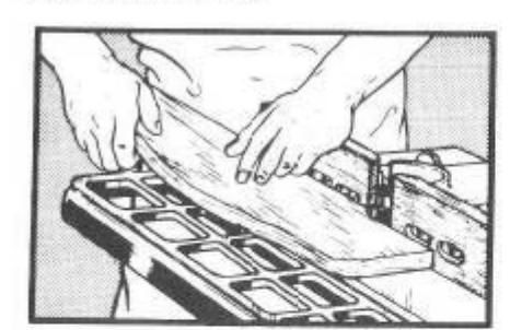
Perfectly squared, straight edges, for butt jointing of two boards, can be molded by using the 1-In. Jointer Cutter and the shaper fence. When planning such a joint, saw your workpieces 1/8to 1/4-in. oversize at each edge to be jointed ... then set your fence faces for exact removal of this excess in one pass. The sawed edge must be straight and parallel to the desired finished edge, and the trailing fence face must be accurately set to the depth of the cut. Hold the work very firmly against both fence faces while feeding it.
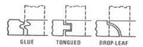
Other types of single-cut, single-pass matched edge joints that can be made in the same manner are shown. For the glue joint, cut one workpiece top-side up and the other, bottom-side up - using the same Reversible Glue Joint Cutter Allow a full 1/4-in, waste on each workpiece edge. Use the Matched Tongue and Groove Cutters for the tongued joint .... allowing a 3/8-in, waste on the piece edged with the tongue cutter; but only 1/8-in. on the other piece. For the drop-leaf joint cut one piece with the Drop-Leaf Bead Cutter and the other with the Drop-Leaf Cove Cutter, Allow 5/8-in, waste on one (left-side) board and 1/8-in. waste on the other. In all cases keep the same fence setup and spindle height setting for both matching cuts. To join an edge to a face, make the face cut as shown by the dotted lines, not allowing for any waste.
JOINTING OR MOLDING TO OBTAIN AN EXACT BOARD WIDTH
Any board that is not too wide can be simultaneously edge jointed or molded and reduced

to an exact predetermined width which can be quickly and easily duplicated for as many additional identical width workpieces as desired. Simply clamp a straightedge 1-in, board to the table positioned so that a workpiece fed between it and the cutter will be reduced to the width desired. In the illustration, this straightedge is shown at the rear (with shaper fence removed); but a wider workpiece can be accommodated if it is placed at front or at side of table.
The workpiece should be sawed to size so that job can be finished (on the shaper) in one pass which will remove not over 3/8-in. (preferably, only 1/8-in.) of waste. Also, to avoid having to reach over the cutter to hold the molded portion of work against the straightedge, use a hold-in (of scrap wood), as shown.

If workpiece is to be tapered instead of squared at the corners, use the same set-up together with Sears Taper Jig (9-3233) or a homemade taper jig, as shown. First saw the workpiece to the approximate shape, then use the jig opening and straightedge position to establish the exact line of the cut.
SHAPER-CUT TENONS
Square
Perfectly square, perfectly centered tenons can be cut at the end of a square workpiece (like a table leg) with the aid of the Universal Jig (page 12) and the 1-In. Jointer Cutter. If leg is tapered, use a wedge, as shown, to block it vertically in the jig. If it is straight, no wedge is

needed. To cut the second, third and fourth sides simply reposition the leg in the jeg for cutting each side, in turn ... without altering anything else. Should a tenon longer than 1 in. be needed, make a second cut on each side with the spindle elevated accordingly.
Oblong
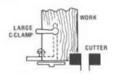
For an oblong tenon (as at the end of a table skirt), do each of the two board faces with the same jig setting, and a set-up similar to the preceding. To do the two board edges, use a large C-clamp to hold work at end of jig, as shown using the same work position and jig setting for each edge.

A round tenon at the end of a square for tapered square) workpiece (like a table leg) is easily cut to exact dimension and concentricity with the center by using a homemade jig like the one illustrated, together with a large collar under the 1-In. Jointer Cutter. The two hori-
zontal jig members must have holes through which workpiese can just be inserted then rotated without wobbling ... and must be far enough apart to afford substantial vertical support for the workpiece. The collar can be hardboard, plywood, plastic or metal ... and must serve to hold the workpiece end up to establish the length of the tenon. After making the setup, start your shaper and lower the workpiece to the cutter until it bottoms on the collar ... these rotate it 350° to complete the tenon.
STRIP MOLDINGS
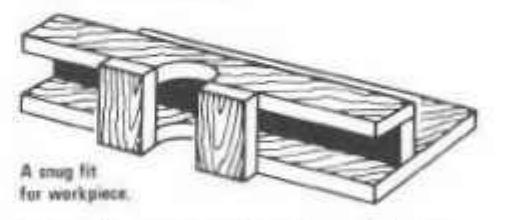
The easiest way to make a strip molding is to mold the edge of a wide board ... then saw off the molded edge to the width desired. Or, if the width is not too thin, you can feed your strip along the shaper fence, using the hold-down, hold-in fingers to keep it in position.
Sometimes, however, it is necessary to mold pre-cut, very thin strips that need more support (to prevent warping as they pass the cutter) than the hold-down fingers can provide. For such strips best construct a strip-molding guide like the one illustrated. Clamped to the table in the right position, this guide will afford sure support and guidance for the strip fed through it (and confined within it).
SHAPING BOWED WORK
If work is only slightly bowed - so that its center will not be too high when it is held with the concave side down - the easiest way to shape its edge is to use a crown block, as shown. The block need not have the same curvature as the work (can be more curved), but must be of a width, length and height to
support the workpiece throughout the operation. Provide a circular hole through the block and its clamping board for the swing of the cutter, as shown. Use a shaper collar to establish depth of cut. While feeding the workpiece across the block, keep the point of the edge at the cutter constantly straight up and down. If block has same curvature as bow of workpiece, this is easier to do.
If the bow curvature is too great to feed the work concave side down, you have two choices: 1) If curvature is regular, use a concave block (like the on-end circle guide, page 19) to slide it in ... against a collar or the shaper fence. 2) If curvature is irregular, feed it freehand (concave side up) against a collar or the fence ... and guide it so that point of edge at the cutter is always squarely aligned with the cutter.
MOLDING ODD-SHAPED WORK
When an odd-shaped workpiece — such as an octagonal-shaped table leg or a cabriole chair leg — is to be finished with adge or face molding, a specially made holding jig is required. Such a jig can be built up from scrap wood so that it will firmly and properly support the work. If feeding against the shaper fence is practical, the jig should have a straight edge; but if work is to be fed against a collar, the contacting jig edge can be shaped to serve like a pattern.
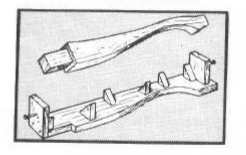
MOLDING PATTERN-SHAPED DUPLICATES
If a number of long, odd-shaped pieces are to be identically contour jointed or edge molded, a "doubling-up" pattern speeds the work. A typical pattern is illustrated. This pattern is so constructed (with guide blocks) that the workpieces can be quickly cropped into place on it for guiding against a collar. In use, all the workpieces — one at a time – can quickly be shaped along one edge; afterwards, with the other side of the pattern against the collar, they can again

be quickly shaped on their opposite sides. The work does not have to be glued, etc. to a pattern of this type.
MITERED-END SHAPING

The mittered end (or side) of a workpiece that is too short to be guided by the fence is best molded by using a miter gauge —as already described, and as shown above. The gauge can be set to an exact angle for accurate contouring (as well as molding) of the end.
MULTI FACE SHAPING OF TABLE AND CHAIR LEGS

A jig like the one illustrated can be used for

accurate multi-face ininitian or molefing of straight or tapered columns. Made of wood, it is designed like a lathe with a didino tailstock the accommentate various length springers) and a stationary beadstock. The "dead" center of the tailstock is a nail for sensel point but the headstock holds a lathe-like sour center centered in an index head and free to rotate on conter. The index head is drilled with a number of soundly snared balas (usually 24) as shown into any one of which a nail can be inverted (through the stationary headstock part) to lock it in the position to which it has here retated If in the position to which is has been rotated. One edge of the jig base should be straight, to slide along the fence for shaping a straight, to slide along the tence for shaping a straight against a straightedge fence, for shaping a tapartic a straightstige intee, for shaping a shaped to any contour desired - or be arranged to hold a pattern - for curved-edge shaning against a collar ... or, as shown, can be shaped to contact stop blocks clamped to the table
The index head can be relocated - by using the nail and a selected group of the equally specied holes - to place 2, 3, 4, 6, 8, 12 or 24 separate sides of a workpiece held between the centers in position (one at a time) for feeding to a cutter. If a straight-edge cutter is used the finished piece will have the selected number of straight (or tapered) sides: the 3-Bead Cutter can be used for reeding: the 1/4-10. Groove Cutter will produce prooved fluting, and many other designs are possible with other cutters Work can be molded end to end or, by using stop blocks, can be molded from point to point short of the ends. Feeding is done by moving the jig with the workpiece in it. To vary the depth-of-cut use different thicknesses of material clamped to the shaper feore - or different diameter collars - for the jig edge to slide against.
ORNAMENTAL EDGE DESIGNS
Many different special-effect edge designs can be obtained by using the various cutters and patterns having contours different from their workpieces. Two such designs are explained
A Varying Depth-Of-Cut Edge
To create this effect you can use a wave-eriged pattern with a straight-edged workpiece, as shown ... or both can be waved for curved as desired) with waves (or curves) that do not match, so that cutter will dig deeper into workpiece at some points than at others.

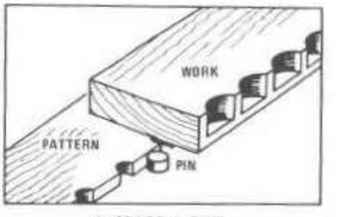
A SPACED CUT
A Spaced-Cut Edge
The cuts are spaced, as shown, by using a pattern with regularly spaced notches to engage a stationary pin. The pin can be a dowel embedded in a board clamped to the table or you can use the shaper guide post. Depth of cut is regulated by using a collar to contact the uncut workpiece edge (as in the illustration) or to contact the pattern under the workpiece fill out is to remove all of edge). To make each cut engage correct pattern notch on pin and pivot work into the cutter to depth allowed by collar. then pivot it back off.
SHAPING DOWELS

Perfectly round dowels can be shaper cut by

ADAPTED FOR DOWEL SHAPING
using one of the quarter-round or radius cutters of proper size. Stock must be sawed square prior to shaping, and four cuts must be planned to round it. Best use a strip-molding guide (page 22) to tightly encompass and guide the workpiece for each of the four cuts.
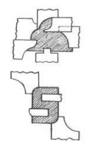
MULTIPLE FIGURE SHAPING
It is sometimes easier to shaper cut a number of identical flat, cut-out figures than to do them separately on a band or jig saw. Two typical figures that can be shaper cut are illustrated. The rabbit requires six different shaper cuts, as indicated ... and the letter S requires four.
Start with a long enough piece of wood of proper width and thickness; do the shaper cutting (against the fence or a collar, or using a strip-molding guide) ... then saw the strip crosswise to produce the recuired, identical flat figures.
TYPICAL SHAPED FIGURES
PANEL RAISING

One type of raised panel is illustrated. This is made by edge-molding the workpiece on all four sides with the 2-1/2-In. Dia. 3/4 Rd. Cutter positioned to leave a cut as shown.
Four other suggested patterns and methods of cutting them are also shown.

THE BELT AND DISC SANDER
COMBINATION 6-IN. BELT, 9-IN. DISC BENCH SANDER
ADVANTAGES OF A BENCH SANDER
Hand sanding is one of the most tedious of woodworking chores. The substitution of electrical power for muscle not only speeds sanding and eliminates fatigue ... it also produces much finer, more uniform work with a saving in sandpaper costs (power-driven abrasives last longer). For large workpieces, heavy enough to remain firmly in position, an electrically powered hand sander generally is preferable; but for small pieces which must be steadled by holding, a bench sander is the only practical solution.
With the Craftsman Belt and Disc Bench Sander you can quickly rough sand to shape, can do fitting of pieces (as for inlay work), can finish sand almost any shape of workpiece with precision, and can do the fine sanding required when building up an exquisite, high-gloss finish.
FEATURES OF THE CRAFTSMAN SANDER
Both a belt and a disc are necessary for complete versatility. A disc is excellent for quick roughing to shape and for convex (outside) contour sanding of smaller pieces; but a disc has the disadvantage of sanding faster at its outer edge (which travels faster) than at its center ...
thus making it diffcult to sand a true straightedge of any length more than a couple of inches. On the other hand, a belt is excellent for true straightedge sanding, for surface sanding and for concave (inside) contour sanding of radii into which the belt drum ends will fit ... but is "more tool" than needed when a disc will do the iob.
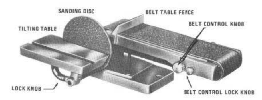
The tilting table (0° to 45°) — which can be positioned for use with either the disc or the belt — makes it possible to hold work steady at any desired angle to the abrasive surface. The adjustability of the belt — from horizontal to vertical position — further enhances the ease with which work can be positioned as desired.
Other desirable features incorporated in this tool are: A belt aligning and tensioning adjustment that is simple and fast. A firm-locking adjustment for bel: tilt, from 0° (horizontal) up to 90° (vertical). Lifetime, sealed ball bearings in belt drums. A miter-gauge table groove for use of a miter gauge.
SEARS BELT-DISC HOBBYIST SANDER
A lighter-duty model (not illustrated) having a 6-in. disc and a 4-in belt is also available. This model also has an adjustable-position belt with a fence and a tilting table that is fitted with a miter gauge.
SHOP-TESTED SANDER ACCESSORIES
EXTRA SANDING PLATES
A SUPPLY OF BELTS DISCS AND CEMENT

mount 3 different grit sandpaper discs ready for quick use. It is easier to change sanding plates than to change discs on a plate.
Replacement belts and discs are both available in coarse, medium and fine grits - for rough to finish sanding. And pressure-sensitive cement permits ready changing of discs.

AN ON-OFF SWITCH
Finger-flip rocker switch provides instant, positive and convenient control ... has extra outlet for tool light.
A MITER GAUGE

A miter gauge with a holddown clamp makes it easier to guide work for miter or compound-angle sanding. Gauge can also be had without clamp.
A CRAFTSMAN MOTOR
For ample power to do all jobs your big sander needs a reliable 1/2 hp 3450 rpm capacitor motor (hobbyist tool needs a 1/2 hp 1725 rpm motor). Don't underpower your tool . order the Craftsman motor specified!
BELT-SANDING OPERATIONS
BELT SELECTION - AND CHANGING
Belts are available in fine, medium and coarse grits. The medium is best for all general shop work. Use the coarse grit only when rough sanding to quickly size or shape a piece; use the fine grit only for finish sanding or sanding be tween coats of paint, etc. To change belts, loosen the belt tension sufficiently to slide the old one off and the new one onto the pulleys then realian and retension the new belt.
SURFACING OPERATIONS
All surface sanding should be done with the belt horizontal.
If workpiece is shorter than belt, use the fence. Position work end against fence, use one hand to lightly press work onto belt and to hold it stationary ... then start the sander and sand until right amount of stock has been removed. Stop the sander to remove the workpiece.
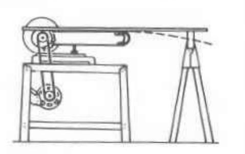
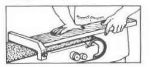
If workpiece is longer — but less than twice the length of the belt — do as above to each and separately. However, if work is more than twice belt length, the fance must be removed . and the work must be traveled in uniform manner lengthwise along the belt until entire surface has been sanded. In this case guide with one hand at board end not in contact with the belt, while using other hand to press lightly down on top over the part in contact with belt. When workpiece is long enough to sag at free end use a sawhorse or bench of proper height to support end and keep work exactly level. If allowed to sag, irregular work will result.
Always send with the grain insofar as possible. If work is narrower than belt, hold it straight with belt travel; if wider than belt, slant it slightly so full width will be sanded as it moves over belt. Try te avoid sanding side-by-side areas separately as this may leave a groove down the center between the areas. Never allow sides to overhang belt in one position ... or belt adoes will leave arcoves.
Sanding is easy to do well. Just remember to let the tool do the work ... don't try to "pressure it" yourself or you'll obtain uneven, grainy results. Above all, keep your hands away from the moving bett or disc ... and don't wear any loose, floppy clothes (sleeves or a tie) to be caucht up by the moving parts.
EDGE AND END SANDING

Edge sanding is done with the belt fence (for short work) or without it (by traveling the work) in the same way surfacing is done. To keep the edge at 90° (or any desired bevel angle) with the faces, board must be held exactly upright (or at proper angle). A simple setup can be arranged by clamping suitable boards to each tide of worksiece ... to be sanded with it. Or you can make and use a side fence (page 31).

Short boards can be edge or end sanded in the manner illustrated, at 900 or at any angle to which fence can be set. However, if board is long it is better to use the tilting table (following).
USE OF TILTING TABLE
All edge or end sanding – at 90° or any angle desired – can be done with the belt vertical, and with the work placed on the tilting table. Angle between tilting table and belt table then determines bevel angle of work edge to work faces. To sand a miter angle (or a compound miter and bevel angle) use a miter gauge in the table groove to guide work at the desired angle. Always hold work firmly down on table, sliding it across the belt as necessary.
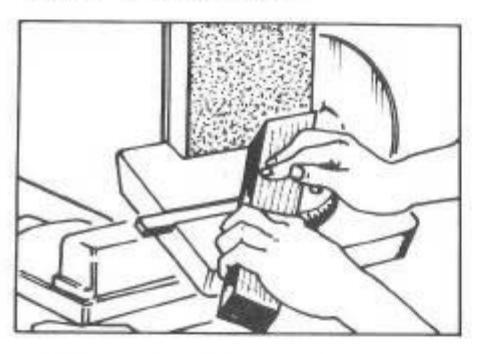
SLACK-BELT SANDING
Slackening the belt – then sanding on the backside of the belt table with the table vertical, as shown – will allow the belt to mold itself around a convex curve that is not too abrupt. This helps to avoid flats created by oversanding at some points, since more of the belt is constantly in contact with the work. Loosen the
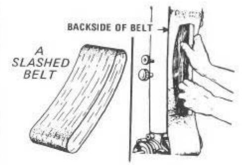
belt just enough so that pressure of work against it will prevent it from running slack enough to slip or buckle. For wide, irregular surfaces a slashed belt will mold to work contour even better.
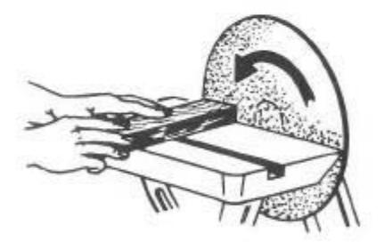
DRUM SANDING

An inside curve can be sanded on the drum at the end of the belt, as shown. Position the belt table for maximum convenience. Sand with the grain insofar as possible.
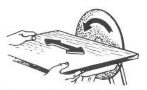
USING BUILT-UP FORMS

Various shape forms can be made to fit on the belt table under the belt, as shown. The top of the form must allow the belt to slide freely and to tract so as not to run off of its pulleys. If belt when slackened won't cover the form, an oversize belt is required. If form has irregular contours, run the belt slack enough to mold itself to the form ... preferably using a slashed belt.

DISC SANDING - USE OF JIGS
GRIT SELECTION - AND CHANGING
Sandpaper discs are available in fine, medium and coarse grits. Cement a new disc to the plate face with Pressure .Sensitive Cement
A DUAL-PURPOSE DISC

Two grits can be cemented to one plate – with the finer grit inlaid at center of a coarser grit, as shown. Do coarser sanding at disc edge; move to center for finer sanding. This speeds production-type work.
HOW TO USE THE SANDING DISC
Disc sanding is primarily for workpieces edges and ends. Do all disc sanding with the work pressed firmly down on the table. Preferably feed small enough work to the "down" (left) side of the disc, keeping in mind the fact that the outer portion of the disc is traveling faster than the inner portion ... and will, therefore, sand faster. To avoid unequal sanding, either move the work constantly from left to right across the down disc side, or turn it over (180°) several times while sanding.
If work extends across the "up" disc side, hold
this side extra firmly to keep it down on the table ... and move work constantly from side to side to avoid having an unsanded portion at the center (where disc does little work).
For bevel-edge sarding tilt the table to the desired angle. For miter-edge sanding, best clamp the work in a miter gauge with holddown ... to assure accurate positioning. For compound-angle sanding, tilt the table and use the miter gauge (set to desired miter angle).
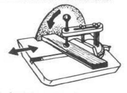
USING A PATTERN
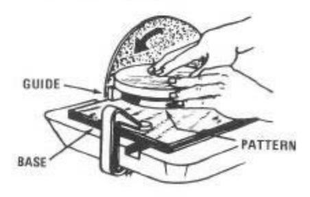
Production of many identical pieces is best done with a pattern and guide. The base is a

piece of wood to fit the table — with a thin metal guide fastened to the inside edge and projecting up, for the pattern to ride against. Fasten a strip to the underside of the base to fit into the miter-gauge slot, so that the guide is almost touching the disc. Make the pattern undersize to allow for the distance between the guide and disc.
SANDING TO A THICKNESS
A set-up such as illustrated will ensure uniform thickness sanding of any workpiece . if backside of workpiece is finished first to provide a smooth contact with the quide.
A SEGMENT PIVOT JIG
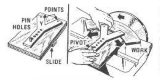
For accurate curvature sanding some type of jig is needed. A simple one for segment work is shown. Use a wooden base (to cover the table top) to hold a pin (dowel peg) for the Y-arm to pivot on. Drive nails through the Y ends to project on underside sufficiently to bite into, and hold, the workpiece. Make the set-up so that just the right amount will be sanded off the workpiece when it is pivoted across the disc
A CIRCLE JIG

For full circle sanding a jig, as shown, is best. The base is made to cover the table top, but has a dovetail groove at down side of disc to hold a bevel-edged slide. Slide can be wood, but a 1/4x1-in. aluminum bar is better. A nail or sharpened screw point serves as the pivot point. The locking screw wedges the slide in its groove to hold it stationary.
Start with the work centered on the pivot point. Move the slide up until the work is sanded in to the desired radius ... then lock the slide and revolve the workpiece to shape the entire contour.
HOW TO MAKE A SIDE FENCE
NOTE
As there are no stops, this fence must be set vertical or at the angle cesired — by using a square or a protractor to gauge the angle between fence face and belt surface. After setting, tighten the wing nuts sacurely to hold the fence in position.
Many belt sanding operations can be made easier by use of a side fence. A homemade fence is illustrated. Use 1-in. hardwood for the fence, beveling the bottom edge at 60o to leave a knife-edge at face side of fence. Groove the
1/4" TOILET-BOWL BOLTS WITH WING NUTS 23/4" = 18x3" FENCE BEVELED EDGE 2.7/8" UPRIGHTS Drill and tap for 1/4" bolts. CAP SCREWS
face horizontally. Embed the studs (toilet-bowl bolts) as close to rear face edge as you can. Use 3/16x3/4-in. aluminum bar stock for the uprights, making slots 1/4x1-in. with tops 2-7/8-in. above belt. Drill and tap belt-table side (opposite disc) to secure the uprights.

| TADLES | |||||||||||||
|---|---|---|---|---|---|---|---|---|---|---|---|---|---|
| DECIMAL EQUIVALENTS | |||||||||||||
| 1/64 == .015625 | 1/4 = .250 | 1/2 = .500 | 3/4 = 750 | ||||||||||
| 1/32 = .03125 | 17/64 = .265625 | 33/64 = .515625 | 49/64 = .765625 | ||||||||||
| 3/64 = .046875 | 9732 = .28125 | 17/32 = .53125 | 25/32 = .78125 | ||||||||||
| 19/64 == .296875 | 35/64 = .546875 | 51/64 = .796875 | |||||||||||
| 1/16 = .0625 | |||||||||||||
| 5/64 = .078125 | 5/16 = .3125 | 9/16 = .5626 | 13/16 = .8125 | ||||||||||
| 3/32 = .09375 | 21/64 = .328125 | 37/64 = .578125 | 53/64 = .828125 | ||||||||||
| 7/64 = .109375 | 11/32 = .34375 | 19/32 = .59375 | 27/32 = .84375 | ||||||||||
| 23/64 = .359375 | 39/64 = .609375 | 55/64 = .859375 | |||||||||||
| 1/8 = .125 | 3/8 = 375 | 5/8 - 625 | 7/9 - 075 | ||||||||||
| 9/64 = .140625 | 25/64 = .390625 | 41/64 = 640625 | 57/64 - 900626 | ||||||||||
| 5/32 = .15625 | 13/32 = .40625 | 21/32 = 65625 | 29/32 - 90625 | ||||||||||
| 1/64 = .171875 | 27/64 = .421875 | 43/64 = .671875 | 59/64 = .921875 | ||||||||||
| 3/16 = .1875 | 7/16 = .4375 | 11/16 = .6875 | 15/16 = 9375 | ||||||||||
| 13/64 == .203125 | 29/64 == .453125 | 45/64 = .703125 | 61/64 = .953125 | ||||||||||
| 7/32 == .21875 | 15/32 = .46875 | 23/32 = .7:875 | 31/32 = .96875 | ||||||||||
| 15/64 == .234375 | 31/64 == .484375 | 47/64 == .734374 | 63/64 - 094375 | ||||||||||
|
Width
in Inches |
* BOARD MEASURE | ||||||||||||||
|---|---|---|---|---|---|---|---|---|---|---|---|---|---|---|---|
| Length in Feet | |||||||||||||||
| 4 | 5 | 6 | 7 | 8 | 9 | 10 | 11 | 12 | 13 | 14 | 15 | 16 | 17 | 18 | |
| 2 | 0-8 | 0-10 | 1-0 | 1-2 | 1-4 | 1-6 | 1-8 | 1-10 | 2-0 | 2-2 | 2-4 | 2.6 | 2-8 | 2.10 | 3.0 |
| 3 | 1-0 | 1-3 | 1-6 | 1-9 | 2-0 | 2-3 | 2-6 | 2-9 | 3-0 | 3-3 | 3.6 | 3.9 | 4-0 | 4-3 | 4.6 |
| 4 | 1-4 | 1-8 | 2-0 | 2-4 | 2-8 | 3-0 | 3-4 | 3-8 | 4-0 | 4-4 | 4-8 | 5.0 | 5-4 | 5-8 | 6-0 |
| 5 | 1-8 | 2-1 | 2-6 | 2-11 | 3-4 | 3.9 | 4-2 | 4.7 | 5-0 | 5-5 | 5-10 | 6.3 | 6-8 | 7.1 | 7.6 |
| 6 | 2-0 | 2.6 | 3-0 | 3-6 | 4-0 | 4-6 | 5-0 | 5-6 | 6-0 | 6-6 | 7.0 | 7-6 | 8-0 | 8-6 | 9-0 |
| 7 | 2-4 | 2-11 | 3-6 | 4-1 | 4-8 | 5-3 | 5-10 | 6-5 | 7.0 | 7-7 | 8-2 | 8.9 | 9-4 | 9-11 | 10.6 |
| 8 | 2-8 | 3-4 | 4-0 | 4-8 | 5-4 | 6-0 | 6-8 | 7-4 | 8-0 | 8-8 | 9-4 | 10-0 | 10-8 | 11-4 | 12-0 |
| 9 | 3-0 | 3.9 | 4-6 | 5-3 | 6-0 | 6-9 | 7.6 | 8-3 | 9-0 | 9.9 | 10-6 | 11-3 | 12-0 | 12.9 | 13.6 |
| 10 | 3-4 | 4-2 | 5-0 | 5-10 | 6-8 | 7-6 | 8-4 | 9-2 | 10-0 | 10-10 | 11-8 | 12-6 | 13-4 | 14-2 | 15.0 |
| 11 | 3-8 | 4.7 | 5-6 | 6-5 | 7-4 | 8-3 | 9-2 | 10-1 | 11-0 | 11-11 | 12-10 | 13.9 | 14-8 | 15-7 | 16-6 |
| 12 | 4-0 | 5.0 | 6-0 | 7-0 | 8-0 | 9-0 | 10-0 | 11-0 | 12-0 | 13-0 | 14-0 | 15-0 | 16-0 | 17-0 | 18-0 |
| 13 | 4-4 | 5-5 | 6-6 | 7-7 | 8-8 | 9-9 | 10-10 | 11-11 | 13.0 | 14-1 | 15-2 | 16-3 | 17-4 | 18-5 | 19.6 |
| 14 | 4-8 | 5-10 | 7-0 | 8-2 | 9-4 | 10-6 | 11-8 | 12-10 | 14-0 | 15-2 | 16-4 | 17-6 | 18-8 | 19-10 | 21-0 |
| 15 | 5-0 | 6.3 | 7-6 | 8-9 | 10-0 | 11-3 | 12-6 | 13-9 | 15-0 | 16-3 | 17-6 | 18.9 | 20-0 | 21-3 | 22-6 |
| 16 | 5-4 | 6-8 | 8-0 | 9-4 | 10-8 | 12-0 | 13.4 | 14-8 | 16-0 | 17 4 | 18-8 | 20-0 | 21-4 | 22-8 | 24-0 |
| 17 | 5-8 | 7.1 | 8-6 | 9-11 | 11-4 | 12-9 | 14-2 | 15.7 | 17-0 | 18-5 | 19-10 | 21-3 | 22-8 | 24-1 | 25-6 |
| 18 | 6-0 | 7.6 | 9-0 | 10-6 | 12-0 | 13-6 | 15-0 | 16-6 | 18-0 | 19.6 | 21.0 | 22.6 | 24.0 | 25.6 | 27.0 |
"The price of a board is computed on the basis of the number of board feet contained in the board. One board foot is equivalent to the amount of stock contained in a piece of board one foot long, one foot wide, and one inch thick. (For purposes of board feet computation, stock which is less than one inch thick is generally considered to be one inch stock.) To determine the number of board feet in a board by use of the above table proceed as follows. Find the vertical column which corresponds to the length of the board (in feet). Then run down this column to the figure which is horizontally opposite the proper width in inches indicated in the side heading. This figure will be the number of board feet in the particular board. If the board is geater than one inch, multiply the figure indicated in the table by the actual thickness dimension of the board.
For a board which is eight feet long, eight inches wide, and one inch thick, it will be found that the table indicates a figure "5-4". (The second digit, "4" indicates the fractional portion, in twelfths, of a board foot — 4/12 foot.) Thus, the board feet contained in the board is 5-4/12 feet or 5-1/3 feet. If the board were two inches thick, then it would be necessary to multiply 5-4 by 2. The total board feet then would be 10-8 or 10-2/3 feet.
POWER TOOL INSTITUTE, INC. SAFETY RULES FOR POWER TOOLS
1. KNOW YOUR POWER TOOL
Read owner's manual carefully. Learn its applications and limitations as well as the specific potential hazards peculiar to this tool.
2. GROUND ALL TOOLS – UNLESS DOUBLE-INSULATED
If tool is equipped with three-prong plug, it should be plugged into a three-hole electrical receptacle. If adapter is used to accommodate two-prong receptacle, the adapter wire must be attached to a known ground. Never remove third prong.
3. KEEP GUARDS IN PLACE
and in working order.
4. KEEP WORK AREA CLEAN
Cluttered areas and benches invite accidents.
5. AVOID DANGEROUS
Don't use power tool in damp or wet locations – keep work area well lit.
6. KEEP CHILDREN AWAY
All visitors should be kept safe distance from work area.
7. STORE IDLE TOOLS
When not in use, tools should be stored in dry, high or locked-up place — out of reach of children.
8. DON'T FORCE TOOL
It will do the job better and safer at the rate for which it was designed.
9. USE RIGHT TOOL
Don't force small tool or attachment to do the job of a heavy duty tool.
10. WEAR PROPER APPAREL
No loose clothing or jewelry to get caught in moving parts. Rubber gloves and footwear are recommended when working outdoors.
11. USE SAFETY GLASSES
with most tools. Also face or dust mask if cutting operation is dusty.
12. DON'T ABUSE CORD
Never carry tool by cord or yank it to disconnect from receptacle. Keep cord from heat, oil and sharp edges.
13. SECURE WORK
Use clamps or a vise to hold work. It's safer than using your hand and it frees both hands to operate tool.
14. DON'T OVERREACH
Keep proper footing and balance at all times.
15. MAINTAIN TOOLS WITH CARE
Keep tools sharp at all times, and clean for best and safest performance. Follow instructions for lubricating and changing accessories.
16. DISCONNECT TOOLS
When not in use, before servicing; when changing accessories such as blades, bits, cutters, etc.
17. REMOVE ADJUSTING KEYS AND WRENCHES
Form habit of checking to see that keys and adjusting wrenches are removed from tool before turning it on.
18. AVOID ACCIDENTAL STARTING
Don't carry plugged in tool with finger on
SOLD BY
SEARS, ROEBUCK AND CO. – CHICAGO, ILL. 60607 – U.S.A. AND SIMPSONS-SEARS LIMITED – TORONTO
Accessories Increase Scope and Quality of Work

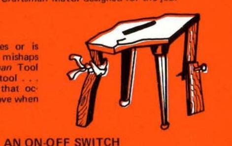
THE RIGHT TOOL BASE
If your tool is mounted so it wobbles or is awkward to reach, it may produce more mishaps than good work. Sears offers a Craftsman Tool Base designed especially for each bench tool . a firm, substantial, proper height base that occupies a minimum space and is easy to move when necessary.

A BELT GUARD
Speeding belts and pulleys have grabby habits . they can grab anything that flaps or floats too near. Use the Craftsman Belt Guard designed for your tool, and save yourself from such grabby, cotton-pickin' "hands".


A FACE SHIELD
No sensible knight ever faced a javelin thrust barefaced. Why should you go barefaced into the shower of flying missels tossed off by a high-speed tool? With a Craftsman Face Shield you can see better than yee olden knight — and won't perspire so much, either.
WHY LIMIT YOUR TOOL'S CAPACITY TO A "ONE-ARM" JOB?

Accessories are designed to increase the scope and proficiency of your tool's operations. Any Craftsman Tool will, of course, perform excellently in doing its primary job – even without accessories ... but it will do more , and do it more easily if you supplement it with all of the Craftsman Shop-Tested Accessories designed for it.
The recommended Craftsman accessories for your Jointer, your Shaper and/or your Belt and Disc Sander are listed and illustrated in this book. You can improve your output, your quality and your safety by using them.

THERE'S A CRAFTSMAN KNOW-HOW HANDBOOK FOR EVERY POWER TOO
THE RIGHT MOTOR


 Loading...