

Accessories Increase Scope and Quality of Work

THE RIGHT MOTOR
If your tool is mounted so it wobbles or is


No sensible knight ever faced a javelin thrust
WHY LIMIT YOUR TOOL'S CAPACITY TO A "ONE-ARM" JOB?

DO MORE WITH YOUR Drill Press
HOV

OVER 100 OPERATIONS DESCRIBED AND ILLUSTRATED

A CRAFTSMAN HANDBOOK

ALL NEW FEATURES OF CRAFTSMAN

ACCESSORIES (P. 4) LET YOU ROUT, DOVETAIL, MORTISE,
DRILL PRESSES

INDUSTRIAL (Floor) MODEL
built-in 60-watt worklight with its own separate switch ... and a conveniently placed motor switch. There is also a quick-setting feed stop for predetermining depth of drilling ... a safe-lock keyoperated chuck ... and an extra-large, ball-bearing, precision-ground quill, operated by a convenient, three-spoke feed handle.
The 15-1/2-in. models have the new, heavy-duty, machined table that is suitable for C-clamp use. They also can be fitted with an auxiliary tilting table which will hold work for drilling at any angle from 0o to 90o. The industrial model has a heavy-duty table, and a tilt-adjustable table is available.
All Craftsman Drill Presses are of professional quality ... easy to set up and use. Properly equipped with shop-tested accessories your Craftsman Drill Press becomes an exceedingly versatile tool, capable of many operations besides drilling (as told in this book).
SHAPE, PLANE, SAND
GOOD WORK, SAFETY REQUIRE Secure Holding Of Workpieces
To drill a perfectly round, straight and centered hole in any kind of material it is necessary to hold the workpiece securely against the rotation of the drill and against any tendency to roll or wobble. The safest, easiest way to hold a workpiece is with a suitable device designed for the purpose. This is especially true if the workpiece is small or awkwardly shaped
ADJ. HOLD-DOWN GUIDE
Bolted to table, the guide serves as a fence for routing, surface planing and similar operations. Use with holddown for drilling.

GENERAL-PURPOSE VISE
For square or round work. Large, 3-in, jaws open to 3 in. Can be bolted to table or hand held for many drilling operations.
ANGLE VISE
For square or round pieces. 2-1/2-in, jaws open to 2-1/2 in.; adjusts for angle drilling from 0° to 90°. Can be bolted or clamped to table.

DRILL-PRESS WORKHOLDE
Excellent for small, oddshaped pieces . extra jaws accommodate various workpiece shapes. 2-5/8x3-in. jaws.
CAM-LOCK CLAMP
Adjustable on column ... lever locks clamp to apply a forceful pressure through arm, which adjusts to 3 lengths and has swivel foot for angular work.

For precision layout and indexing — as well as holding — for drilling, grinding, milling, etc. 8x5-in. table rotates 3600; dials in 1000ths.; 40:1.
UNIVERSAL COMPOUND VIS For drills, shapers, lathes.
For drills, shapers, lathes, etc. Provides precision lateral feed in two directions; one jaw swivels, other has movable face; slide graduated 900 R or L; 7x7-in. table; opens to 4-3/8-in.


YOUR VERSATILE DRILL PRESS

USES OF WORK HOLDERS
IMPORTANCE OF HOLDERS
Some drilling can be done while holding the work by hand; but, for accuracy and safety, all small workpieces, all those which can wobble or roll, and all those which could be twisted out of your hand by rotation of the drill should be more securely held. It can be very painful if drill should rotate a hand-held piece.


Your 15-1/2-in. drill-press tables (standard and tilting) are designed for the use of large Cclamps ... which are excellent for securing large-enough, flat workpieces. To avoid marring workpiece surface, use thin pieces of scrap wood between surface and clamp jaws.
THE HOLD-DOWN GUIDE

Used as a hold-down, this device is excellent for drilling operations in which the drill is likely to lift the work when being extracted . and for firm holding of flat pieces (which can be exactly positioned against the fence). With the hold-down turned aside, the fence makes a reliably positioned guide for routing, grooving, planing and similar operations.
A BOLTED-DOWN VISE

Work-holding vises are especially useful for holding pieces too small to be held by other means . particularly metal workpieces. While such a vise, if heavy enough, can often be safely hand held on the table, much greater accuracy is obtained if the vise is bolted in place.
THE ANGLE VISE

This work-holding vise can be set to any angle, up to 900 ... which is a great advantage when angle drilling, or when it is necessary to position the vise jaws out from under the drill (as they will be with vise raised vertically to 900).
THE CAM-LOCK CLAMP
Because of its superior holding power this column held clamp is very useful for securing extra long or wide, unwieldy workpieces.
MILLING-TYPE VISES

These micro-adjustable vises are required for all types of drill-press operations on small metal pieces in which holes, key slots, etc. must be located, spaced or shaped with machine-shop precision.
LAYING OUT HOLES
GENERAL LAYOUT PRACTICE
Before any project is started, a plan is usually prepared. The dimensions, shapes, hole locations, etc. on the plan are then marked on the stock to be worked. Such marking of the work-piece constitutes "layout", and may be done with the most simple or most precise measuring instruments – depending upon the nature of the job.
LAYOUT TOOLS
The tools shown at the top of this page will provide all the accuracy needed for the average home workshop.
Most useful of all tools is the 12-in. combination square. The square head and adjustable blade make this tool useful for accurate measurements from the workpiece edge, and for laying out parallel lines. When the square head is replaced by the center head, the tool can be used for center marking round work.
Dividers and calipers are useful for transferring measurements to the workpiece, and for scribing soft surfaces. Dividers are also used for scribing circles and for locating measurements from point to point. The surface gauge has wide application. Its fine-adjustment screw and scribing point permit laying out within a thousandth of an inch. It is also convenient for scribing horizontal lines on irregularly shaped objects, such as the waterline on the hull of a ship model.
The scriber is generally used for marking on metal; in wood working, a sharp carpenter's pencil, scratch awl or sharp knife is more satisfactory. A center punch is used to prick the surface of metal where holes are to be drilled.
MARKING AND SCRIBING
Generally, wood is easily and plainly marked; but scribing on some metal surfaces cannot be made distinct. On dull or rough cast-iron surfaces, chalk, white shoe polish, soap stone, or whiting can be used to provide a background for the lines or marks. Polished steel should be coated with a copper sulphate solution. A 20% silver nitrate solution serves equally well on copper or brass. A purple dye (Dykem, procurable at machine-tool supply houses) can be used on any metal.

DIMENSIONING HOLES
When extreme precision is required, lay out actual hole size by scribing two circles around the center mark. The outer circle is the exact diameter of the hole, and is lightly prickpunched at four places. The smaller circle is a checking mark. As the drill progresses into the work, comparison with the inner circle will reveal the accuracy of the operation, and permit necessary correction. The outer circle provides final proof of accuracy.
CENTER LINING
To approximately centerline rectangular work, use the combination square and a pencil to mark two lines on the work, equidistant from respective edges. The closer those lines are placed, the easier it is to judge the centerline. For exact accuracy, adjust blade of combination square to measured center distance, before marking work.

CENTERING RECTANGULAR WORK
The exact center point of a perfectly square or rectangular piece can be located by marking diagonals between opposite corners. These lines will cross at the center.
CENTERING ROUND WORK
When center head is used on combination square, any two lines scribed along the inner edge of the blade will intersect at the exact center of a truly round workpiece.


LOCATING HOLES
Accurate dimensions can be transferred from a scale or plan by use of dividers. Hermaphrodite calipers are useful when measuring in from edge of workpiece. Mark hole centers prior to beginning work.
LOCATING DOWEL HOLES IN WOOD
When the work is to be joined edge-to-edge, square-up all pieces and clamp them together. Then, with a combination square, draw dowel center lines across edges to be joined. Separate the pieces and bore holes where marked, with the face of each board against a fence, and the holes centered between the edges.

Another method of joining work edge-to-edge is to draw a centerline down the edge of the boards and mark on it the dowel centers. Cut off the heads of small brads or common pins and insert these (with pliers), blunt end first, at the dowel centers. Leave about 1/8 inch of each point projecting. Line-up remaining board with the first, and press them together. If dowel holes are already bored in one piece, the same method can be followed by the use of dowel pops.


When doweling joints other than edges, cut out a template of some thin metal with very small holes drilled where dowel centers are to be located. The template must be shaped so that itcan be accurately positioned on both pieces. Mark dowel centers with a scratch awl.
LOCATING HOLES ON IRREGULAR SURFACES
Place a surface gauge on a flat surface and set a combination square, on end, next to gauge. Adjust gauge until scriber point touches scale at height desired. Now, set workpiece adjacent to gauge and mark workpiece with gauge scriber.

WOOD BORING

BIT SELECTION
Several types of wood bits are generally in use for wood boring with a drill press. Most popular for clean, sharp-sided holes in soft- or hardwoods and plywoods are the power wood bits . These are available in the one-piece type – each made only for a one-size hole (in sizes ranging from 3/8-in. to 1-1/4-in. or larger), with 1/4-in. shanks ... or in the interchangeable-size type which has one common 1/4-in. shank with a number of detachable cutters (ranging from 1/4-in. to 1-1/2-in. or larger). Both types are very fast and accurate in operation, and easy to resharpen.
For small holes (from 1/16-in. up to 1/2-in.) you can use wood drills (carbon-steel, for wood only), which have 1/4-in. shanks . or you can use metal-cutting twist drills available in all fractional, numbered and lettered sizes ( page 12 ), with shank sizes relative to drill sizes. Though similar to twist drills, the wood drills have longer lips, better adapted to fast, clean drilling in all kinds of wood.
Very deep holes (approx. 4 in. up to 18 in.) require electrician's drills – commonly available
in 1/4-, 1/2- and 3/4-in. sizes. Holes larger than 1-1/4- or 1-1/2-in. in diameter are drilled with an expansive bit , a hole saw or an adjustable hole saw . The expansive bit (usually 1-1/4- to 3-in. dia. capacity) is good for deep through or blind holes (up to about 6 in. deep) – but the screw point must be filed to remove the threads, so that the bit will not feed itself into the work. Hole saws come in various sizes (1- to 3-or-more-in.) or in a type that has interchangeable blades (1- to 2-1/2-in.)... and are used to plug-cut wood up to a maximum thickness equal to the height of the hole-saw blade (approx. 1 in.). The adjustable hole saw will cut diameters from 1-1/8- to 2-1/2-in., to about 1-1/4-in. deep.
NOTE
A "plug" is a through cut. If not cut all the way through, a plug must be removed by a chisel.
Very large dia. plugs (up to 8 in.) can be cut with a circle cutter - to a depth of about 1-1/2-in.
Holes for wood screws are most quickly bored with a wood-screw pilot bit of a size designated for the screw to be used. This bit simultaneously (when sunk to proper depth) drills the correct size screw hole; counterbores for the screw shank, and countersinks for the screw head. Or, you can do the countersinking with either of the countersinks illustrated.
SPEEDS OF OPERATION
Speeds vary greatly with the type of bit, the diameter and depth of the hole, and the grain and hardness of the wood. In general, bits up to 3/4-in. diameter can be run up to 5000 rpm; those from 3/4 to 1-in. up to 3000 rpm. Expansive bits will overheat and burn at speeds higher than 1000 rpm. In all cases, you can determine the correct speed by watching the work carefully; if the hole starts smoking, the speed should be reduced before continuing, to prevent burning of the bit.
FEEDING AND HOLDING WORK
The feed pressure required for drilling holes in wood is largely determined by the feel of the work, which is gained through practice and experience. Bits should not be forced into the wood, but must be allowed to cut their way through. Maintain an even, steady pressure, slacking off as the bit approaches the breakthrough point. If the hole is deep, back the bit out occasionally to clear the accumulated chips and prevent jamming and overheating.
Whenever possible, the work should be held down on the table with clamps or a holddown device. Clamping is essential if the bit has but one cutting edge, as is the case with the expansive bit and circle cutter. The drill table should always be positioned so the bit is lined up with the clearance hole provided in the center of the table. Fixtures, such as V-blocks, made to hold work for boring with wood bits are better if made of wood, to prevent damaging the drill bit.
BORING A THROUGH HOLE
There are two generally accepted methods of boring a hole completely through the work. In one method, a piece of scrap wood is placed
directly under the hole, and the bit is fed down through the work into the scrap piece. If the work is not backed up in this manner, the bit will invariably splinter the bottom of the work as it breaks through. When drilling a series of holes, shift the scrap piece to place a new, flat surface under each new hole being drilled.
The second method requires use of the feed stop, so that the bit is fed into the work until the point just starts through the opposite face. Then withdraw the bit and turn the piece over. Place the drill point in the hole left by the point as it came through, and complete the operation.
BORING TO DEPTH
To bore to a marked depth, mark the depth of the hole on the side of the work, bring the bit down to the mark and adjust the feed stop. To bore to a measured depth, lower bit to touch work, lock quill, set feed-stop pointer to depth measure and run knurled nut down onto pointer. The hole can now be drilled exactly to the depth desired.
BORING DEEP HOLES
Holes longer than 3 inches are generally classed as deep holes. The average wood drill has a working length of about 4 inches, and holes to this depth can be bored if care is taken to lift the bit from the hole repeatedly to clear away chips. If a deeper hole is required, use an electrician's bit ... then raise the table to obtain additional depth, after reaching the bottom of the quill travel. Through holes deeper than 4 inches are more easily bored by drilling from both ends. This requires careful alignment to insure that the holes from each end will meet exactly.

BORING TO DEPTH
HOLES

In order to align holes drilled from opposite ends, use this procedure: First, drill as deep as you can into the workpiece, then remove it. Second, clamp a 3/4-or-more-in. thick scrap piece to the table, and drill almost through it. Third, peg this last hole with a dowel over which the hole in your workpiece can be fitted to position the workpiece – then drill in from the opposite side.
BORING LARGE DIAMETER HOLES

The largest power wood bit is 1-1/4 to 1-1/2 in. If a larger diameter hole is required, use an expansive bit, a hole saw or a circle cutter. The expansive bit must be used if hole is to be blind (not through), or if it is to be a deep through hole (but remember to file threads off of the screw point, page 8 ). A hole saw can be used if workpiece is not too thick ... and will do cleaner work, especially in soft woods. The circle cutter will drill very large diameter holes but, also, can be used only if workpiece is not too thick. Also, for wood cutting without tearing, the cutter end should be ground to an 80° angle.

When drilling any large diameter hole – especially with a one-side tool like the expansive bit or the circle cutter – safety demands that the workpiece be securely clamped down to prevent its movement. Any slight movement will also ruin the work. In addition, use a very slow speed – not over 500 rpm with the circle cutter – and very light feed pressure.

When it is necessary to drill a series of holes in sequence, excellent use can be made of pre-cut spacer blocks in conjunction with a fence. Cut blocks to the exact dimensions of the hole spacing and place them between end of work and a clamped stop block. Then remove blocks one at a time as the holes are drilled. If spacing is to be irregular, cut and assemble blocks ac-

to set one on the other, with work on top and a dowel of same size as holes to be drilled. Nail two boards together with one nail, the point of which will project up to be a pivot point for the workpiece. Draw your circle on top piece with nail at center ... then clamp bottom piece (only) to table so that circle will rotate accurately under the bit. Place work on iig (properly centered) and drill one hole through work and jig. Remove work and rotate top jig piece exact distance to place second hole location under bit ... then clamp jig so that neither piece can move. Now replace work on jig and insert dowel through (first) hole in work down into hole in top jig piece - then drill second hole through work. Continue using dowel through last hole drilled in work and into the jig, as a means for locating each new hole.
BORING IN
The drilling of round or cylindrical pieces rework from rolling, under the pressure of the drill. The simplest fixture is a homemade Vblock. In use the V-block is located on the table so the drill lines up exactly with the center of the V. When clamped in this position, holes can be drilled in any size piece of round stock with assurance that they are on center. To use a vise, first scribe a centerline on the workpiece end with a center head. This mark is then aligned with a chucked drill, and the work is clamped in the vise. The scribed line and the drill are lined up by eye as the drilling is started. For rough work, a hole can be drilled through a circular piece if it is centerlined, as above, and held against a fence for a steady

Never attempt to balance a piece on end by hand, for end boring. The most practical way to hold a workpiece on end is in a vise (clamped to the table), if the workpiece is not too large. A large piece can be centered at bottom between the hold-down guide fence and blocks clamped to the table ... and can be held at top by the cam-lock clamp or a similar homemade device.
BORING SCREW HOLES

When two pieces of work are to be assembled with a screw, you can either use a screw pilot bit ... or drill two holes. One hole is drilled through the upper piece and is large enough to pass the shank of the screw. The lower piece – into which the screw will be threaded – is drilled with a core hole smaller than the first. Preferably, assemble the two pieces – either with clamp or by gluing. If a correct size pilot bit is now used it will drill both pieces and countersink for the screw head, all at once. Otherwise, the larger shank hole is drilled first and the smaller core hole is then drilled down beyond it.
COUNTERBORING

Counterboring is the process of enlarging the outer end of a drilled hole, usually for the purpose of accommodating the head of a bolt or screw which must be sunk below the surface. In woodworking, the enlarged portion of the hole is drilled first, since wood bits do not track well in previously drilled smaller holes. The smaller bit will center accurately in the point hole made by the larger drill.
COUNTERSINKING

Countersinking is similar to counterboring, except that the countersink accommodates the head of a flat head screw, permitting the screw head to be sunk flush with the work surface. When countersinking a series of holes in the drill press, it is good practice to set the feed stop for uniform depth of cutting. Center each hole by lowering the countersink into it while countersink is stationary.
METAL DRILLING
REAMER
OUNTERSINK CIRCLE CUTTER REAMER
DRILL SELECTION AND SPEEDS
Although there are many styles of drills for special purposes, the twist drill (commonly called "drill") is the most generally used in the average shop for metal drilling. This drill has two flutes, two cutting edges, and, in sizes up to 1/2-in., a straight shank that is the same size
NOTE
Drills larger than 1/2-in. with steppeddown shanks to fit a 1/2-in. chuck are available. However, it is not practical to use a drill larger than your chuck size for drilling ferrous metals, unless your press is equipped with an oversize motor.
Twist drills are made in three series of sizes: The fractional series, the numbered series, and the lettered series. With few exceptions each series provides a slightly different selection of sizes, with the result that there is a drill size for practically any desired hole, within a few thousandths of an inch. Numbered and lettered series drills available are listed in the tables on page 32. Fractional series drills are usually
made in increments of 64ths of an inch, up to
Twist drills are made of either carbon or highspeed steel. Carbon-steel drills are satisfactory for the "softer" metals . but are not recommended for drilling ferrous metals, unless operated at very slow speed. High-speed steel drills may be operated at higher speeds and in harder metals, stay sharper, and last longer. The latter definitely should be used in drilling monel, stainless and other tough steels, and are more satisfactory for use in fiber, hard rubber, asbestos, bakelite and similar plastic materials.
The speed at which a drill is operated is very important to drill life and the quality of the work. Proper press speeds for various drilling operations are shown in the chart on your press (p. 2).
FEEDING THE DRILL
The rate of feed must be judged by feel, and by observation of the chips. Avoid the common error of using too slow a speed and too heavy a pressure. Apply a firm, steady pressure until drill is about to break through, then ease off.
PROPER HOLDING OF WORK
hand; but it is much better practice to hold work securely by some mechanical method. pecially, should be firmly secured. The breakthrough of the drill, coming suddenly, can easily pull work from hand causing severe cuts. and breakage of the drill
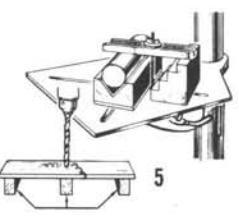
STRAP CLAMP A simple method to stop rotation of long flat work is to fix bolts in table slots and hold work down between them (fig. 1). Or, a C-clamp in place of one bolt is even better. Other clamping devices can be of many types, depending upon ingenuity of operator. Among suggested devices are the grooved edge V-block and Y-clamp - an excellent combination for holding round pieces (fig. 2). Irregular-shaped pieces can often be together with a C-clamp (fig. 3). Parallels used in conjunction with long bolts anchored in the the work table to act as stops (fig. 4), and various sizes of step blocks (fig. 5) will also be found to have many uses. Then there is the much used strap clamp (fig. 6), which can be purchased or can be made at home from a shaped pieces, any one of which may come in handy for some specific work-holding job. The main purpose is to obtain a solid, firm, level mounting of the workpiece. It is also important - especially when drilling thin pieces - to avoid spring or give in the work under pressure of the drill. Use wood blocks to support area under drill.

PARALLEL
TEP BLOCK
PIPE V-BLOCK
ANGLE IRON
Y-CLAMP

A drill vise offers special conveniences in holding work. Often, it can be held by hand, as it affords the necessary grip, weight and leverage to prevent work from turning. In precision work, however, the vise should be secured to table with a C-clamp, or by bolts through the vise lugs. If possible, place work in vise so that drill is above vise channel; otherwise, put a scrap of wood or soft metal under location of hole to prevent drilling into the vise. The auxiliary V-jaw and wedge-shaped jaw are both very useful for holding irregular-shaped work.

THERE ARE MANY WAYS IN WHICH TO USE A DRILL VISE
PRECISION WORK HOLDING

One of the milling-type vises (p. 3) is the finest of holding devices. Offering all the advantages of the drill vise, it also affords the added convenience of precise work positioning under the drill. Lavout can be done with a pattern fastened on top of work, or by calculating movements of the vise jaws. If hole sizes are to be different, it is common practice to spot all the holes with a center (or very small) drill drilling to the finished sizes after the spotting lavout has been made. The jaws of a milling vise will hold most types of small work, but if the workpiece is of a character which makes use of the jaws impractical, these may be removed and the part can be clamped to the vise table by one of the methods previously described.
LUBRICATION OF WORK
Cast iron, brass, copper, lead and babbit should be drilled dry (without use of lubrication) ... but other metals require lubrication at point of drilling to prevent overheating and dulling of the drill. For aluminum, preferably use kerosene ... for all other metals (except "dry" ones above) use machine oil. Start by placing a drop in your center-punch hole, then – after drill lips have fully penetrated, raise the drill and add another generous drop. As drilling progresses, raise the drill and add more lubricant whenever necessary to replenish it (also, whenever it is advisable to raise drill to clear the chips).
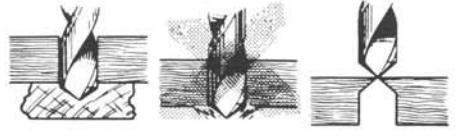
DRILLING CENTER HOLES
The combination drill and 60-degree countersink, also called a center drill, is very useful for making center holes in work to be mounted on a lathe – and for spotting and drilling starting holes for the larger drills.
STARTING A HOLE
A center-punch mark should always be made before starting a hole in metal. If this is not done, the drill may wander before penetrating the metal, and may break; or the hole may be off-center. When the larger drills are used, a center-punch mark may be too small to guide the chisel point of the drill accurately. In such cases, the hole may be started with a smaller drill or with the center drill. It is good practice, whenever accuracy is important, to lay out on the work a checking circle of same size as hole to be drilled, so that progress of hole can be

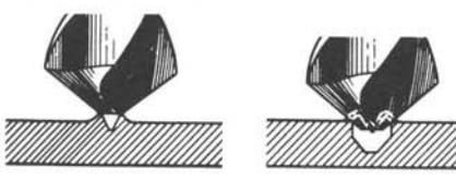
DRIFTING A HOLE
If drill wanders off exact center, first try to determine cause. The work surface may not be level. Or, the center-punch mark may have been at fault. In most cases, however, an improperly sharpened drill is to blame. Correct original cause before proceeding, if possible.
To correct the hole, use a cape chisel and cut out some metal on the side toward which the drill should return. When drill is again entered into the work, it will tend to drift to the chiseled side of the hole.
SPOT-FACING AND COUNTERBORING

Spot-facing and counterboring are similar in that the hole itself is not changed in any way, but the surface around it is cut away. Spotfacing consists of machining a round, smooth surface at the face of the hole where it is desirable to have a flat seat for a bolt head or nut.
This is generally done on castings and other irregular surfaces. Counterboring is simply a deep spot-facing operation and permits, for example, recessing a bolt head below the surface. Both counterboring and spot-facing are generally done with the counterbore, a special tool available in sizes for all standard bolts. Counterbores can also be made by first drilling a small hole for bolt shaft, then drilling a larger top hole for bolt head. The resulting counterbore will then have a slightly tapered bottom edge.
Flat-head screws are designed to be sunk flush with the surface of the part they enter. To provide a correctly tapered recess in a drilled hole for this purpose, it is necessary to use a countersink. An 82o machine-screw countersink is most widely used. Countersinking is usually done at the same speed as drilling, and the countersink must be located in the hole while stationary, before starting.
REAMING
When it is necessary that a hole be of an exact diameter, it is first drilled slightly undersize – about 1/64th of an inch smaller. The finished size is then obtained by use of a reamer, which is run through the drilled hole at a speed approximately two thirds of drilling speed. Lubrication is required, the same as for drilling (p. 14). Reamers are not designed for the indiscriminate enlarging of holes, and should not be used to remove large amounts of metal.

LAPPING
Lapping a hole is a process similar to reaming, except that the cutting agent is an abrasive
material instead of steel cutting edges. Less material is removed, and a more polished finish is achieved. The lap is a round metal rod charged with abrasive grains (emery or silicon carbide in very fine grit). It is of a softer material than the work. Before charging, it should be no looser than a good turning fit in the hole. Charge the lap by rubbing it with the abrasive or (for best effectiveness) roll it between steel plates, one of which is coated with the abrasive material. Laps should be run at slow speed with plenty of lubricant. A light lubricant permits faster cutting, but results in a coarser finish.


Large diameter holes are sometimes enlarged by boring. This operation is performed with a boring bar — a metal rod or shaft which holds a cutting tool at the working end. Boring bars with a screw adjustment to set the depth of cut are the most satisfactory; but the simple type shown in the illustration can be made in the home shop for occasional use. When boring, use a very slow speed and take very light cuts, to prevent chatter.
HONING
Although honing is a highly specialized process generally requiring the use of specifically designed equipment, small hones can be used in the drill press to correct out-of-roundness and bell-mouth within tolerances of approximately one thousandth of an inch. Special coolant is available and must be played upon work in a steady stream. Work is accomplished entirely by feel and must be constantly checked from start to finish. Most manufacturers of hones will supply detailed instructions.

DRILLING OTHER MATERIALS AND
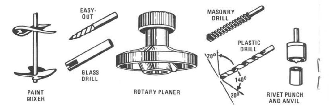
MASONRY DRILLING

Gritty materials cannot be drilled with metalcutting drills ... will quickly round off and ruin them. For drilling all such materials as masonry, tile, brick and stone you must use a masonry drill . This type of drill has one (or two) cutting lips made of tungsten carbide, and a smaller diameter shank designed to lift out the ground-up dust. Drills are readily available in 3/16-, 1/4-, 5/16-, 3/8-, 1/2-, 5/8- and 3/4-in. sizes.
For the type of work usually done on a drill press no starting punch mark is needed, if work is securely held in place. In some cases, however, it may be more practical to start a hole with a star drill. When drilling, fairly heavy pressure may be needed to keep the drill biting in ... it is better to force the drill rather than to let it whirl without cutting (which glazes the surface and makes it harder to cut). Use a high speed ... 5000 rpm or better. If drill should stop biting in, pull it out and break the glaze with a star drill or marble chisel to allow the drill to start cutting again. In drilling concrete it may also be necessary to thus break up any large pebble the drill hits head on. Should dust start to clog the hole, lift the drill - while running - to clear it out.
GLASS DRILLING
Holes may be drilled in glass by either one of two methods. One procedure employs a steel or brass tube slit at the working end. A circular dam of putty is mounted on the surface of the glass around the hole area. Then a quantity of 80-grit silicon carbide, in a liquid mixture with turpentine, is poured into this reservoir. The drilling tube is driven at a speed of about 500 rpm, and a light but even pressure is maintained on the feed handle. (Unless the surface supporting the glass is dead level, the glass may crack under drill pressure.) Lift the drilling tube from the work regularly to permit new abrasive to flow into the cut. Do not drill through, but turn glass over and finish from reverse side.
Small holes may be drilled with a hardened piece of drill rod ground to a triangular point, or with a triangular file. Lubricate the drill with turpentine in which some camphor has been dissolved.
PLASTIC DRILLING
Acetate and acrylic plastics can be drilled with ordinary twist drills for metal; but, for the best results, the drills should be repointed to work with a scraping rather than a cutting action. The drill point for plastics should be ground to
MISCELLANEOUS OPERATIONS
an angle of about 140 degrees, and the lead of the drill should be reduced to limit its tendency to hog into the work.
Moderate speeds should be used, and the drill must be lifted from the hole frequently to prevent clogging or burning. If the work will be exposed to variations in temperature, it is advisable to drill bolt or rivet holes slightly larger than required to allow for expansion and contraction. When drilling thermo-setting plastics, lift drill often to avoid raising the temperature to the melting point.
CUTTING PLUGS AND DOWELS

Shallow plugs from 1-in. to 3-in. diameter are best cut with a hole saw, if the center hole (left by the guide bit) can be refilled with plastic wood, and not be objectionable. Otherwise, plugs – and dowels (up to about 2 in.) – must be cut with a plug cutter. Illustrated is a type of cutter available (in various diameters and lengths) at specialty houses. You can also make a satisfactory cutter by sharpening and slitting a brass or steel tube to the approximate design of the commercial type.
Plugs – used mainly for capping the counterbored parts of screw holes – are always cut with the grain running across – at a speed of about 2400 rpm. Dowels are cut with the grain running lengthwise – at a speed of about 1300 rpm.
STARTING TAPS

When tapping – especially through thin sections of metal, such as tubing – the drill press may be used to advantage in starting the tap straight. After drilling the hole, use a countersink to make a cut about 1/64-in. deep. This helps start the tap and eliminates need of removing the burr raised at top of hole. Fit a starting, or plug tap into the chuck, bring it down to the hole, and turn the quill by hand. Do this slowly and carefully to prevent tap breakage.
The three common types of taps are the starting, plug, and bottoming taps. To produce cleaner threads and reduce tap breakage, a starting tap should be used first when tapping into hard or tough metals.
ROTARY PLANING

The rotary planer (p. 4 and 16) will fit all Craftsman drill presses – and others having a similar safe-lock chuck. This planer has a collar by which it is locked onto the spindle, in place of the chuck (which gives it safe and cleanworking rigidity). For all planing operations the press should be operated at 6000 to 8500 rpm. And, for safety and clean, accurate planing, some type of fence along which to guide the workpiece should be used.
CAUTION
This planer is designed only for surface planing of boards that can be laid flat upon the table. Do not attempt to use it for edge or end planing (which should be done with a shaper cutter, p. 25) .
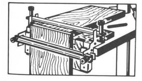
An excellent fence jig is easily made. Use a piece of 1/2-in. plywood long and wide enough to support your largest workpiece. Rout or dado a 1/2-in. groove 1/4-in. deep, parallel to and 2-in. in from the back edge. Glue two 2-in. high strips of the plywood in this groove, to form a fence that extends from end-to-end – but leaving a 3-in. wide gap at the center.
Clamp this jig to table with C-clamps behind the fence, locating it forward or back as needed to properly position the work.
Plan to take shallow (not over 1/8-in. deep) cuts, making as many additional deeper cuts as necessary to finish the job. Set and lock the quill for each depth (either by eye or by actual measurement), prior to starting the motor. Feed from left to right. If work is wider than one cut, shift your fence and/or turn work 180° to finish all of surface before resetting depth of cut. Using this method, unwarped boards up to 8-in. wide can be surfaced on one or both sides, and be reduced to exact desired thickness.
MIXING PAINT
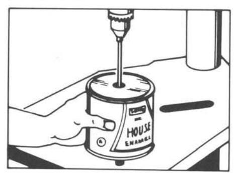
A fast-action paint mixer can be used in the drill press for easy mixing of paint in the can. Punch hole in center of can top and pass paint mixer through it — then be sure to put top tightly back on can before starting press. Hold can in your hands and operate press at the slowest speed.
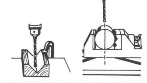
SPINNING RIVETS

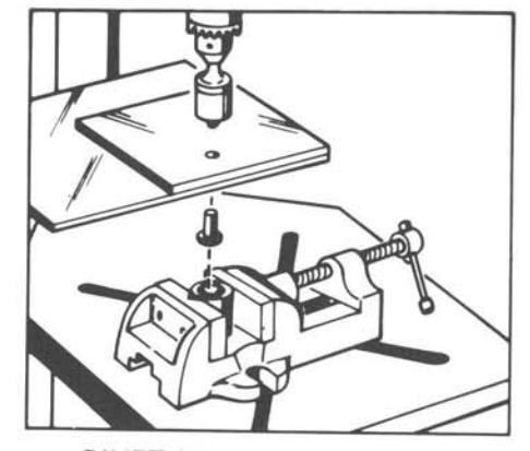
RIVET SPINNING SET-UP
A punch and anvil, of same type used for hammering rivets, can be used for spinning hollow rivets on the drill press. Bolt anvil to table or hold it in a bolted-down vise, and insert punch in the chuck. Punch should turn at approximately 1300 rpm. When work is placed with rivet head in anvil, two or three light hammerlike blows with the revolving punch can be administered by using the feed handle. Rivet must be a snug fit for good results.
DAMASKEENING

All that is required for damaskeening, or spot finishing, is a hard rubber rod of suitable diameter and some abrasive grains such as emery, aluminum oxide, or silicon carbide, of about 150 grit. Mix grains with oil and spread resulting paste on work. Then lightly press revolving rod to surface. Speed should be about 1500 rpm, and feed should be of uniform pressure and duration. Work out a pattern in advance, and use guides to achieve uniform spacing. A hard eraser can be used on soft metals.
ROUTING AND CARVING
BIT SELECTIONS
All the bits shown have 1/4-in. shanks . and should be held in the collet chuck illustrated (which gives proper horizontal support to the shank). Veining router bits (1/8-, 3/16- and 7/32-in. sizes) are for grooving; the straight bits (1/4-, 5/16-, 3/8- and 1/2-in.) are for grooving and cleaning out recessed areas; the dovetail bits (1/4- and 1/2-in.), for dovetail notching and grooving; the stair (11/16-in.) and V-groove (1/2-in.) bits, for special grooving and edge chamfering. All router bits can also be used for panel or letter raising and carving. For edge shaping there are the cove and bead (also for quarter-rounding) bits, both in 1/4- and 3/8-in. sizes . . and all of which fit the same 1/4-in. arbor furnished with two different size pilots.
GOOD ROUTING PROCEDURES
Never use a chuck without a holding collar; if you do not have above collet chuck, you can use the safe-lock chuck ( p. 2 ), but be certain that shank is well up inside and chuck is tightly locked. Operate press at highest speed (8500 rpm).
When feeding, remember that bit rotates clockwise, and tendency will be to kick workpiece outward from left side of bit (as viewed from any side of table). For best results, do not cut deeper than 1/4-in. in hardwood or 1/2 in. in softwood in a single pass. (For any freehand work, best reduce these depths to half.) If necessary, make two or more passes at increasing depth(s). Feed slowly to prevent burning of bit and work (especially in hardwoods).

Always lock the quill after setting bit to desired cutting depth. Do not use a router bit for drilling (it isn't made to cut downward and will tear the wood, burn the bit and/or jam). To start grooving or routing inside a workpiece edge, first drill to desired final depth, then begin routing from this hole.
A ROUTING JIG
Straight line and convex-curve grooving (in from the edge) can be guided very satisfactorily by the fence of the hold-down, guide (p. 3) ... but for rabbeting, chamfering and edge shaping you need a fence into which the bit can be recessed, as necessary. Such a fence is provided by the homemade (plywood) jig illustrated, which can be clamped to the table in any position desired (using the 1-1/2-in. wide portion behind the fence). With this jig you can groove to the center of a 9-in. board, or edge shape any convenient-size workpiece.
STRAIGHT GROOVING

It is almost impossible to groove a true straight line without a fence. If work isn't too long, use the hold-down guide fence (illustrated) ... otherwise, use a routing jig or a straightedge clamped to the table. Feed left to right.

This is practically the same as with-grain grooving ... except that a back-up block of scrap should be used to prevent splintering at the end of the groove, if groove goes out at back edge. Also, if workpiece is too long to hold flat, provide a support for outer end so work can slide in horizontal position.
CURVED GROOVING
A Perfect Circle

Perfect circle grooves are made by using a pivot, which can project through workpiece (if not objectionable) or partially into underside. A dowel or stout nail will serve as the pivot. Fix pivot in a flat board of suitable size to hold workpiece, and fasten board to work table.
Other Convex Curves

Grooving of any convex curve that is to be parallel to an identically curved edge can be guided by holding the work in contact with a fence (preferably, the router-jig fence which has a cut-out to make grinding easier). Work must be swung, as groove progresses, to keep point of contact directly behind center of bit. If groove doesn't parallel edge, a pattern must be used ... also, if groove is too deep to make in one pass.
Concave and Compound Curves

For grooving any other type of curve that will be parallel to an identically curved edge, use a pivot . instead of the fence. A small dowel set into a flat board that can be clamped to the table makes a good pivot. It must be located directly behind the bit centerline. Again, point of contact must always be directly behind the cutter . and if groove is too deep or not parallel to edge, best use a pattern.
PATTERN GROOVING

A TYPICAL PATTERN SET-UP
Almost any type of groove can be cut using a pattern and a pivot (set-up as for concave grooving, preceding). The pattern can be a sawcut template (like one illustrated) ... or a board that has been grooved to desired contour so that it can be guided by engaging the groove over the pivot. It is advisable to have outside contour of pattern identical to outside contour of work. Work must be held securely to pattern so they move as one; use nail points (as shown), or rubber cement, or tape edges together. As you feed the work, keep pattern constantly and squarely in contact with the pivot.
RABBETING AND CHAMFERING

Typical rabbets and chamfers are as illustrated. To cut either type, the work must be guided by one of the straight- or curved-grooving methods ... and, when a fence is used it must have a center cut-out (as in the router jig , preceding) so bit can recess in it. To cut a chamfer, use the V-groove bit at depth desired; or use the tilting table (properly tilted) together with a straight router or the bead bit.
ROUTER MORTISING

Blind- or through-grooved mortises having rounded corners are easily cut with a router bit. Nearly all mortises are stopped grooves (closed at both ends). Therefore, the groove must be started with a drilled hole. Use a wood bit or drill of same diameter as the router bit you will use ... and drill to depth desired for finished mortise, placing hole somewhere (preferably at one end) within groove area. Now rout out the mortise taking as many passes as necessary to make it desired width and depth ... and using a fence as a guide so sides will be true. Cut the tenon with a circular saw (preferably using a dado blade), and round off the tenon corners to fit the mortise corners.
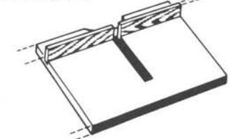
DOVETAIL GROOVING

A dovetail router bit will make a straight (usually cross-grain) groove that can be used to form a lapped dovetailed joint (useful for joining shelves to their supports and for T-lapping beams, as illustrated). The groove can be full length, or be stopped at one end. The mating wedge can be saw cut... or the shelf wedge can be chamfer cut with the dovetail bit and the tilting table set to the proper angle.
EDGE FINISHING

A variety of cove and quarter-rounded (and combination) edge finishes can be (straight or curved) routed, using the cove and/or bead bits ... or by combining these cuts with different rabbet and/or chamfer cuts. If a pilot-fitted bit is used, keep work edge in contact with the pilot; but bits may be used without a pilot. For curved edging, substitute a pin (positioned directly in front of bit shaft) as shown. For straight edging, use the router jig , and recess the bit as required.
CARVING
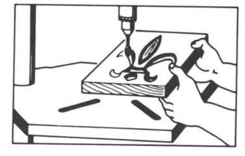
This is simply routing to a design, traced or stenciled on workpiece surface. Begin by roughing in your design (to very nearly finished dimensions and contour) with a suitable router bit(s) ... using the preceding straight-, curvedor pattern-grooving methods . or by moving the work freehand around on the table. If edge curvatures are desired, these can then be created with the cove or bead bits (but remember, these bits will not cut at bottom center where pilot fits). For additional fine finishing and decorative effects you can then use any one of the 1/4-in. shank rotary cutters available (a typical one is illustrated). This finishing (but not heavy routing) can be done as shown, with the quill locked.
DRILL-PRESS DOVETAILING


Dovetail joints, like those commonly used on desk and dresser drawers, are cut with the help of the dovetail attachment. This is a jig designed to hold the two workpieces to be jointed, and to guide the work to the dovetail bit so as to cut both pieces at once (and identically).
With this attachment you can make perfect flush or lipped dovetail joints, such as only a master craftsman could make without it.
BIT SELECTION AND SPEED
Practically all dovetails are cut with the 1/2-in. dovetail bit. The above attachment is designed for this one bit alone; use of any other size bit would require a different attachment. As in all routing operations, the bit should be held by the collet chuck (p. 19) ... but can be held in the safe-lock chuck if securely chucked.
Work can be done rapidly it a high spindle speed is used; and, generally, the higher the speed the cleaner the work. Recommended spindle speed is 8500 rpm. Lower speeds can, however, be used if workpieces are fed very slowly and carefully to prevent tearing.

The dovetail attachment is completely assembled when you receive it, but provision is made for the addition of a table top extension to support your work. This extension must be 7-3/4 in. wide by 12 or more in. long. It can be made longer if desired. Mount the wooden cleat (packed with your dovetail attachment) to the top-rear end of the extension (as illustrated), using the No. 9x3/4-in. flat-head wood screws in the countersunk holes in the cleat. Secure the front end of the extension to the cleat already mounted on the attachment, using more of the same screws.
SETTING UP THE WORKPIECES
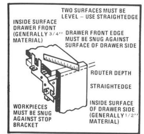
Cut the two workpieces to exact size before dovetailing. When one piece is thicker than the other - as is generally the case when a drawer front and side are being dovetailed - place the thicker piece flat on the horizontal top of the fixture, with the inside workpiece face on top. Place thinner piece against vertical face of fixture, with inside workpiece face at the outer side. Butt both pieces firmly against the respective stop brackets at the left side of the fixture, true up the top edge of the vertical piece to make it flush with the top side of the horizontal piece, and secure both pieces by tightening the hold-down clamp knobs. In tightening the hold-downs, draw them down equally at both ends so that workpieces will be firmly held; but do not overtighten them to the extent of distorting the fixture. When secured to the fixture, the vertical workpiece will be offset to the right of the horizontal workpiece because of the wider vertical stop bracket.
SETTINGS FOR A FLUSH JOINT
Starting at the edge of the horizontal workpiece (where it butts against vertical workpiece), measure in a distance equal to the thickness of
the vertical piece less 1/8 in. Draw a line parallel to edge at this distance. Now hold a flat board against the vertical workpiece so that it projects up above the horizontal piece, and place the comb on top of the hold-down bar with outer rounded edges of the teeth touching the flat board. If the drawn line is visible between the comb teeth, when looking straight down, this is the proper comb setting. In this case, hold comb in position and place router stop on top of it with edge of stop directly above the drawn line. Slots in router stop and comb must be aligned with screw holes in holddown bar; and washers and screws are now used to firmly secure the comb and stop in position.

If comb hides the drawn line, move it back until line is barely visible at innermost edges of slots between comb teeth, and secure it in this position without using the router stop. Comb slots will serve in place of the stop, in this case.

Check all comb and stop settings carefully. Exact settings are important (even 1/32 in. one way or the other will make a poorly fitted joint). The bottom of the router bit must cut into the horizontal piece a distance exactly equal to the width of the vertical piece. Being 1/2-in. wide at the bottom, and being mounted on a 1/4-in. shank, the cut taken by the bit will extend 1/8 in. - 1/2x(1/2-1/4) - beyond the point at which the shank strikes the stop (or comb). This is the reason for so exactly setting the stop and comb.
SETTINGS FOR A LIPPED JOINT

Frequently, drawers are made with a small projecting lip at each front edge to provide a neat fit without binding at the sides. When setting the comb and router stop for this type of joint, move the pencil line inward from the edge of the horizontal piece by an added distance equal to the exact width of the desired lip. After dovetail is cut, lip can be formed on edge of drawer front by sawing off excess wood.
SETTING DEPTH OF CUT

Of similar importance is the exact setting of the depth of cut. Place fixture on drill table and set quill for a 3/8-in. deep cut, as measured on side of vertical workpiece. Lock quill.
CUTTING THE DOVETAIL
Place fixture on drill-press table with workpiece on left side. Then rotate table to bring work in approximate position for feeding it to the bit.
As it is absolutely necessary that fixture be kept flat on table top during cutting, it will be helpful to place a heavy weight on top of that part of fixture or workpiece that is above the table. Start at either right or left side and pull work into bit until bit shank is as far inside the end slot of the comb as it can go. From now on until finished, keep bit shank in contact with edge of comb, so that bit enters wood to full depth of each slot; but do not use more force than necessary. Move progressively from slot to slot until entire dovetail is cut.

It may be necessary to turn and twist work to avoid striking the drill press column. If so, plan how work is to be fed to the bit before starting, or practice with scrap lumber. Use of a column collar (p. 2) , to support the table and permit changing the table position when half through a cut, will make cutting of wide dovetails easier. Do not, however, allow table to swing free while feeding work to the bit.

If necessary, work can be moved to opposite side of table and be fed to the bit from other end of fixture, to complete a half finished cut.
Cut right front and left rear drawer corners at one end of fixture, then cut other two corners at other end. Rub vaseline on comb edge to reduce wear of comb and bit shank.
USE OF THE MORTISING CHISEL
ADVANTAGES OF MORTISING CHISEL
Hollow-chisel mortising has the advantage (over router-bit mortising) of making a square-cornered mortise . so that corners of tenon can be square. In the cases of small and/or shallow tenons this makes for stronger joints; and in all cases makes it easy to obtain a perfect fitting joint.
TOOL SET-UP AND SPEED
A mortising chisel consists of two pieces: a hollow chisel and a matched drill bit to work through the chisel. Sets are available in 1/4-, 3/8- and 1/2-in. sizes. A mortising chisel housing is also required ... to secure the hollow chisel to the drill press. This housing is attached to the (non-revolving) quill above the (revolving) spindle, so that the chisel can be moved up and down but does not rotate (although the drill bit inside it, which is held by the chuck, does rotate). Instructions for making this simple installation are furnished with the housing.
When installing the drill bit in the chuck, it is very important to position it (up in the chuck) to leave at least 1/64-in. clearance between the bit lips and the chisel bottom (to prevent the two parts from scraping together).Tighten chuck very securely.
Operate the 1/4-in. chisel at about 3600 rpm; the 3/8- and 1/2-in. chisels at about 3800 rpm... no more. Also, for mortising operations you should use the hold-down guide (p. 3) , using the fence to guide successive cuts and the hold-down to prevent chisel (when being extracted) from lifting work off table.
MAKING THE MORTISE
Lay out the mortise dimensions on the workpiece, then set the fence so that chisel edge will coincide with this layout when work is against the fence. Adjust the hold down to ride close on the surface of the work, and set the feed stop to the depth of the mortise. Use short, successive cutting strokes, freeing chisel from work at each stroke to rid it of chips. Make the first cut at one end of the mortise, then take additional cuts until finished. The second and succeeding cuts should overlap each preceding cut about 1/3 of the chisel width. Any shape or width of mortise can be cut by properly adjusting the fence.


DRILL-PRESS SHAPING

nuts (see page 20). There is also a 6-piece cutter set (9-32906) that includes nos 3284, 3291, 3285, 3290, 3289
The fence should be bolted to a (table-size or larger) board of 1/2- or 3/4-in, plywood which. in turn, can be clamped to the drill-press table. Provide a circular hole through this board under the spindle, large enough for your widest cutter to recess in it. Always feed from left to right ... and operate press at top speed (8500 rpm). Take light cuts and make several passes if
STRAIGHT-EDGE SHAPING
COLLARS

Start with both fence faces adjusted for depth of cut (into edge) your cutter will make during this (first or only) pass. After edging about 4 inches, stop and readjust face on right side so it will just contact the shaped portion of the work ... then finish this edge and do any others like it. (With practice you'll learn how to adjust right face, before you start.) If more passes are needed, both faces must be readjusted for new depth of cut(s).

desired cut . and the quill locked.

Do all of one edge without stopping, if possible. If edging all around, do cross-grain edges first ... then do the with-grain edges.

If only part of the edge will be removed, the shaper collars (p. 26) are used for shaping curved edges. If all of the edge is to be reing and a number of telescoping rings with on the adapter below or above the cutter.

Feed work straight in to contact the collar then keep it in solid contact with collar at all times while shaping the edge. A starting block (as shown), to rock work on when first pushing it in toward collar, will help control the initial

When an entire edge is to be removed in a curved-edge shaping operation there is no bearing surface left to contact the collar ... so a pattern must be used (below or above the work) to serve this purpose. A pattern must have the same edge contour as the finished work, but must be recessed all around to allow for proper contact with the collar (as shown). Attach it firmly to work with nail points or rubber cement.
FINISHING AND DECORATING WOOD AND METAL


ACCESSORY MOUNTINGS AND SPEEDS

All shafted tools can be mounted in the safelock chuck (p. 2), but the rotary files and grinding points should, preferably, be mounted in a collet chuck (p. 19) ... as this will hold them more rigidly against side thrust. For the 1/4x20 threaded sanding drum (and any similar accessories) use the adapter (p. 26). All these accessories can be operated at top drill-press speed (8500 rpm), with these exceptions: a slower speed and/or much lighter feed pressure is needed when sanding or filing wood if rate of cutting is too fast; and a slower speed may be needed when filing metal, if the file fails to bite in.
NOTE
Remember, all these accessories will revolve clockwise; work feeding should be done at front side (or front bottom), from left to right.
WOOD FINISHING
Drum Sanding
A drum sander is excellent for smoothing edge contour work. The quickest and simplest way is

to simply hold the workpiece freehand (preferably, with knuckles resting on drill-press table to steady your hands), and feed the edge as required to the drum sander. Always lock the quill, for all sanding operations.

Or, you can construct a simple table, like one shown, with a recess for the drum, that can be clamped to the drill-press table . and which will allow you to feed work flat into the sanding drum.
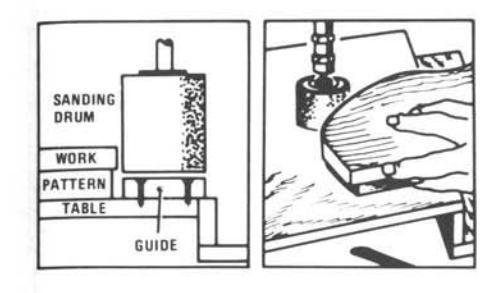
For precision sanding to depth, use a pattern and a guide. The guide is a wood disc, of same diameter as the sanding drum, secured to the table (above) directly under the drum. The pattern is a piece of wood having the same contour as the workpiece, and sized to contact the guide when workpiece is against the drum at final depth to which it is to be sanded. Hold work onto pattern with nail points or rubber cement.
Disc Sanding

Although not too practical for surface sanding of large pieces, the sanding disc (on drill press) provides a fast method of end and/or edge sanding of smaller pieces that can be hand-fed to it from underneath. By bracing your fist on the drill-press table you can steady the workpiece for reasonably level sanding ... or the disc can be lowered so that work can be slid across the table, sandwiched between the table and the disc. Feed from left to right ... and use a fence (behind) to keep work traveling straight.
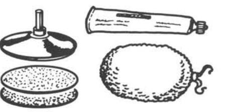
Polishing
The lambswool bonnet (mounted on the rubber disc that also holds sanding discs) is excellent

for polishing filled, stained, oiled or warped wood. Apply filler, etc. to the wood . then hold it in contact with the revolving bonnet until desired finish is obtained, using drill-press table for leverage (as in disc sanding, above).
Hole Enlarging – Rough Contouring

The rotary (wood) files are excellent for side cutting (as in routing) to enlarge a hole ... convert a round hole to elliptical (or other) shape ... or to smooth-shape any contoured inside or outside edge of a wooden workpiece. Those that cut on the end (in addition to side cutting) can also be used for dressing decorative carvings. The metal files will do extra smooth finishing (especially on hardwoods). In all cases, hold work very steady and feed delicately, to avoid over-cutting.
CUTTING ROSETTES AND BUTTONS
Recessed rosettes and raised buttons – in various decorative designs – are easily cut (drilled to desired depth) with a properly shaped cutter. For the cutter use a properwidth power wood bit ( p. 8 ) . and regrind it to the (bottom) contour required (resharpening the ground edge to same bevel as original

bottom edge). Shape only one-half of the bit, grinding other half up out of the way, to avoid necessity of perfectly matching the two halves. Always use the feed stop to limit depth of cut. To create individual buttons, rubber cement thin stock to a backing ... then cut deep enough for outer spur of cutter to completely sever the thin stock (so that buttons can afterwards be separately pried loose from backing).

the (revolving) buff, then applying the work to the front side of the buff. Use light to medium pressure. Apply additional compound as needed to maintain a rapid cleaning and shining result. The felt polishing wheel is used afterwards ... to remove all traces of the buffing and/or for polishing with a cleansing paste (such as a silver polish or wax) that is first applied to the work.
METAL FINISHING
Wire Brushing

Both types of wire brushes are very useful for paint or rust removal and burnishing. Work is generally fed freehand, but it is best to position the drill-press table so you can brace your arm(s) against it for leverage. Use light ( not heavy) pressure so that the wire tips can do the work. Always wear goggles or a face shield.
Buffing and Polishing
Buffing is accomplished by first applying a buffing compound (available in stick form) to
METAL FILING AND MILLING

The 1/4-in. shafted rotary files, as held in a drill press, are very useful for enlarging, reshaping and loose-tolerance reaming of holes in various metals ... and for freehand edge smoothing and limited shaping. They also can be used for grooving and carving of metals other than steel, if work can be held in a vise or be laid fiat on table. In either case, depth variations can be achieved by using the quill feed handle, and straight or curved grooves can be obtained the same as in wood routing ( p. 19-21 )... though progress is much slower, and very light cuts must be taken.

Precision grooving, etc. of small enough objects can be accomplished if the work is held and fed by one of the milling vises ( p. 3 ) – but carbide burrs (rather than the high-speed files ( p. 28 ) should be used, especially for working steel. Operate press at slow (600 to 1000 rpm) speed.
NOTE
Files will be clogged if used on a metal (especially aluminum) soft enough to be worked with woodworking tools. Use lubricants the same as for metal drilling (p. 12).
DEBURRING AND GRINDING

Deburring and similar grinding operations on ferrous metals are done with the 1/4-in. shafted grinding points (p. 28), which come in a variety of shapes. (These are not useful on softer metals, which will quickly clog them.) If a column collar is used under the drill-press table, small enough objects can be vise held and rotated (by swinging the table) under a flat point for surface grinding (as illustrated). Vise or hand-held objects can also be moved along a fence... or be freehand fed.
SHARPENING

The grinding points are also excellent for reedging of badly dulled and pitted edges that must be ground back into shape and cutting contour. Finer edging – as for a knife – can be accomplished using the sanding drum, instead (if re-edging is not required, or has already been done). For razor-sharp honing, finish the job by using a glass, hard rubber or steel honing rod chucked in the drill press... and by passing the edge lightly across it on alternate sides, while holding the edge at exactly the finished (ground or sanded) angle to the rod.

TABLES
DECIMAL EQUIVALENTS
| ALLOWING STORAGE MARK | |||
|---|---|---|---|
|
1/64 = .015625
1/32 = .03125 3/64 = .046875 |
1/4 = .250
17/64 = .265625 9/32 = .28125 19/64 = .296875 |
1/2 = .500
33/64 = .515625 17/32 = .53125 35/64 = .546875 |
3/4
= .750
49/64 = .765625 25/32 = .78125 51/64 = .796875 |
|
5/64 = .078125
3/32 = .09375 7/64 = .109375 |
5/16
= .3125
21/64 = .328125 11/32 = .34375 23/64 = .359375 |
9/16
= .5626
37/64 = .578125 19/32 = .59375 39/64 = .609375 |
13/16
= .8125
53/64 = .828125 27/32 = .84375 55/64 = .859375 |
|
1/8 = .125
9/64 = .140625 5/32 = .15625 11/64 = .171875 |
3/8
= .357
25/64 = .390625 13/32 = .40625 27/64 = .421875 |
5/8
= .625
41/64 = .640625 21/32 = .65625 43/64 = .671875 |
7/8
= .875
57/64 = .890625 29/32 = .90625 59/64 = .921875 |
|
3/16
= .1875
13/64 = .203125 7/32 = .21875 15/64 = .234375 |
7/16
= .4375
29/64 = .453125 15/32 = .46875 31/64 = .484375 |
11/16 = .6875
45/64 = .703125 23/32 = .71875 47/64 = .734374 |
15/16
= .9375
61/64 = .953125 31/32 = .96875 63/64 = .984375 |
| DIAMETERS OF NUMBERED DRILLS | LETTERED DRILLS | ||||||
|---|---|---|---|---|---|---|---|
| Drill | Diameter' | Drill | Diameter | Drill | Diameter | Drill | Diameter |
| No. | Inches | No. | Inches | No. | Inches | No. | Inches |
| 80 | .0135 | 53 | .0595 | 26 | .1470 | A-15/64 | .2340 |
| 79 | .0145 | 52 | .0635 | 25 | .1495 | B | .2380 |
| 78 | .0160 | 51 | .0670 | 24 | .1520 | C | .2420 |
| 77 | .0180 | 50 | .0700 | 23 | .1540 | D | .2460 |
| 76 | .0200 | 49 | .0730 | 22 | .1570 | E—1/4 | .2500 |
| 75 | .0210 | 48 | .0760 | 21 | .1590 | F | .2570 |
| 74 | .0225 | 47 | .0785 | 20 | .1610 | G | .2610 |
| 73 | .0240 | 46 | .0810 | 19 | .1660 | H—17/64 | .2660 |
| 72 | .0250 | 45 | .0820 | 18 | .1695 | I | .2720 |
| 71 | .0260 | 44 | .0860 | 17 | .1730 | J | .2770 |
| 70 | .0280 | 43 | .0890 | 16 | .1770 | K—9/32 | .2810 |
| 69 | .0292 | 42 | .0935 | 15 | .1800 | L | .2900 |
| 68 | .0310 | 41 | .0960 | 14 | .1820 | M—19/64 | .2950 |
| 67 | .0320 | 40 | .0980 | 13 | .1850 | N | .3020 |
| 66 | .0330 | 39 | .0995 | 12 | .1890 | O—5/16 | .3160 |
| 65 | .0350 | 38 | .1015 | 11 | .1910 | P—21/64 | .3230 |
| 64 | .0360 | 37 | .1040 | 10 | .1935 | Q | .3320 |
| 63 | .0370 | 36 | .1065 | 9 | .1960 | R—11/32 | .3390 |
| 62 | .0380 | 35 | .1100 | 8 | .1990 | S | .3480 |
| 61 | .0390 | 34 | .1110 | 7 | .2010 | T—23/64 | .3580 |
| 60 | .0400 | 33 | .1130 | 6 | .2040 | U | 3680 |
| 59 | .0410 | 32 | .1160 | 5 | .2055 | V—3/8 | .3770 |
| 58 | .0420 | 31 | .1200 | 4 | .2090 | W—25/64 | .3860 |
| 57 | .0430 | 30 | .1285 | 3 | .2130 | X | .3970 |
|
56
55 54 |
.0465
.0520 .0550 |
29
28 27 |
.1360
.1405 .1440 |
2
1 |
.2210
.2280 |
Y—13/32
Z |
.4040
.4130 |
POWER TOOL INSTITUTE, INC. SAFETY RULES FOR POWER TOOLS
|
1. KNOW YOUR POWER TOOL
Read owner's manual carefully. Learn its applications and limitations as well as the specific potential hazards peculiar to this tool. |
10. WEAR PROPER APPAREL
No loose clothing or jewelry to get caught in moving parts. Rubber gloves and foot- wear are recommended when working out- doors. |
|||
|---|---|---|---|---|
|
2. GROUND ALL TOOLS – UNLESS
DOUBLE-INSULATED If tool is equipped with three-prong plug, it should be plugged into a three-hole elec- trical receptacle. If adapter is used to ac- commodate two-prong receptacle, the adapt- er wire must be attached to a known ground. Never remove third prong. |
|
|||
|
KEEP GUARDS IN PLACE
and in working order. KEEP WORK AREA CLEAN Cluttered areas and benches invite accidents. AVOID DANGEROUS ENVIRONMENT Don't use power tool in damp or wet loca- tions – keep work area well lit. KEEP CHILDREN AWAY All visitors should be kept safe distance from work area. |
|
|||
|
STORE IDLE TOOLS
When not in use, tools should be stored in
dry, high or locked-up place – out of reach of children. DON'T FORCE TOOL It will do the job better and safer at the rate for which it was designed. |
|
|||
|
USE RIGHT TOOL
Don't force small tool or attachment to do the job of a heavy duty tool. |
18. AVOID ACCIDENTAL STARTING
Don't carry plugged in tool with finger on switch. |
|||
|
SOLD BY
SEARS, ROEBUCK AND CO CHICAGO, ILL. 60607 - U.S.A. |
||||
AND SIMPSONS-SEARS LIMITED - TORONTO


 Loading...