

USING A MITER BOARD
The ordinary (square) miter for joining two boards is cut with the miter gage set at 45 degrees. To cut the opposite end of the same board, turn the board upside down. If board cannot be turned upside down, move the miter gage to the opposite side of the saw and reset it to 45 degrees in the opposite direction. If work is allowed to creep (page 11) the resulting joints will be out of square (as in the illustration). For this reason, cabinet joints are best made with the use of a miter board.


A simple miter board can be quickly made as illustrated. The two mitered stops should be cut at the same time, with the miter gage set at 45 degrees. Guide strips are ar-

ranged to slide in the miter gage grooves. Workpieces should be square cut to the desired overall length plus 1/4 inch to allow for saw kerfs, and are then miter cut in the jig.
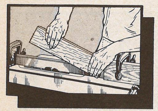
THE TENONING JIG
Cutting tenons, like making other end cuts (page 14), requires special holding of the work. Two homemade tenoning jigs that will make it easy to hold and position the work are illustrated. Each is fitted with a stop shoulder that is cut away to allow passage of the saw blade when the jig is close enough to the blade to make the inside cheek cut of a tenon. Jigs designed to travel in the miter gage groove, and having adjustments for accurate positioning of the work, can be purchased.
CUTTING TENONS
When cutting tenons, make the shoulder cuts first, using a stop block to position these cuts accurately. Then make the two cheek cuts and the edge cut.
There are three methods of making the cheek cuts. The simplest method is to clamp the work to the tenoning jig and position the jig and fence so as to cut out the cheek on the side away from the jig. Then turn the work around and cut the other cheek, without moving the fence. This method centers the tenon accurately but the widths of the tenons will vary if there are variations in the thickness of the wood.
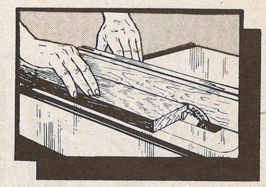
Accurate width tenons can be cut by using a backing block (as illustrated). This block should be the width of the desired tenon plus the width of the saw kerf. If there are variations in the thickness of the wood, tenons cut in this manner will not all be accurately centered.
Accurately centered, exact width tenons can be cut by using two saw blades of the same diameter, with a collar between. Paper discs can be used with the metal collar to space the blades as required. The work is clamped to the jig, and the fence can be positioned, as needed, to accurately center each tenon that is cut.


--- 17 --
GROOVER SAW
dado and groover saws

DADO SET
A Typical Dado Set
The dado saw or head, as it is also called, is a special set of blades for cutting grooves and dados on the circular saw. This head consists of two solid, full-circle outside blades and a number of two-toothed chipper blades for use between the outside blades.
A typical head set contains two ¼s-inch thick outside blades, four ¼s-inch thick chipper blades, and one 1/16-inch thick chipper. With this assortment you can cut grooves as follows: ¼s inch (1 outside blade); ¼ inch (2 outside blades); 5/16-inch (2 outside blades and the 1/16 chipper) — and additional widths increased 1/16 inch each, up to 13/16 inch maximum. The outside blades cut like a combination blade; the chippers act as planers to smooth out the area between the two outside blades — and cannot be used except between two outside blades or they will tear the work.

A dado insert must be used to replace the standard table insert. This can, if necessary be a piece of plywood cut to fit the table insert opening and provided with a wide slot for the dado head.
Dado blades are generally smaller in diameter than standard saw blades so that the depth-ofcut gage probably cannot be used. Each setting of the dado head must be made by aligning the top of the blades with a mark on the work. Settings should be checked on scrap lumber. As the splitter and guard cannot be used, these should be removed for dado operations.
Whenever two or more chippers are used, space the swaged ends of the chippers as evenly as possible around the circumference of the assembled head. Avoid having the teeth of two or more chippers in a straight line across the head. Each swaged chipper end must fall in a gullet of the adjacent outer blade.
Fractional Thickness Adjustments
Fractional adjustments in the thickness of a dado head can be made by using paper washers to seperate the outside blades from the chippers. In this manner thickness variations up to 1/16 inch can be obtained. Such adjustments are often useful in securing a tight fit for a grooved joint.
HOW THE GROOVER SAW WORKS
A groover saw is a wide, 8-tooth blade with chisel-type teeth designed for cutting grooves. It will do the same work as a dado head but is not variable in thickness as each saw will cut only one size groove. Standard widths generally are: 1/8, 3/16, 1/4, 5/16, 3/8, 1/2, 5/8 and 3/4-inch; but other sizes can be obtained.
HANDLING WORKPIECES

Operations with the dado head are much the same as with a standard blade. It must be remembered, however, that the dado head takes a bigger bite in the workpiece; and that the likelihood of kickback is therefore increased As the splitter, and
consequently the anti-kickback pawls, cannot be used, the workpiece should be held down firmly by hand, or by use of a hold-down jig like the one illustrated.
REGULARLY SPACED GROOVES
Regular spacing of grooves can be done by using the stop rod on the miter gage to engage the last groove cut, and so set the position for
— 18 —

the next groove. Another method is to use a notched stop block (below) to fix the starting positions of the various grooves. This block should be clamped to the table well ahead of the blades so that work is free from it before cutting operation begins. The block can be notched in regular steps, or according to any desired pattern. A third method is to clamp a yardstick to the miter gage (or miter gage extension), and position the work for any desired spacing of grooves by referring to the inch marks on the stick.
WIDE GROOVES
When a groove wider than the dado head is needed, it must be cut in two or more passes. Use a notched stop block to start each pass.
When moving the workpiece over to make additional cuts, move it just a little less than the thickness of the head so that the cuts will overlap. Also remember that right side of head will establish right edge of cut, and the left side of the head will establish left edge of

CUTTING GAINS AND STOPPED GROOVES
A gain is a groove that is closed at one end; stopped grooves are closed at both ends. Both are used in making joints.

-19-
A gain is started like an ordinary groove or dado; but a stop block is used to fix the end of the cut. To

locate this block, place work alongside dado and position it so that back edge of dado lines up with the desired end of the groove. Butt the block up against back end of work, and clamp it to the table or fence. Always stop saw before removing finished work.
To cut a stopped groove, both the end stop block and a starting block must be used. The starting block is located just like the end block, and is clamped to table or fence. Butt front of work against starting block, and lower work onto the blades.
DADO TENONS
Tenons are usually cut with the widest dado combination. If tenon is still wider than the dado head, make the inside
cut first and widen the tenon by making later cuts, advancing toward the end. The notched stop block already described can be used.

DADO RABBETS
Rabbets are quickly cut with the dado head, using the fence as a guide. Use a combination a little wider than the rabbet to insure a clean edge. Preferably make the cut on the edge
dado and groover saws (cont'd)
away from the fence; otherwise an auxiliary fence, cut out like a moulding fence, must be used.

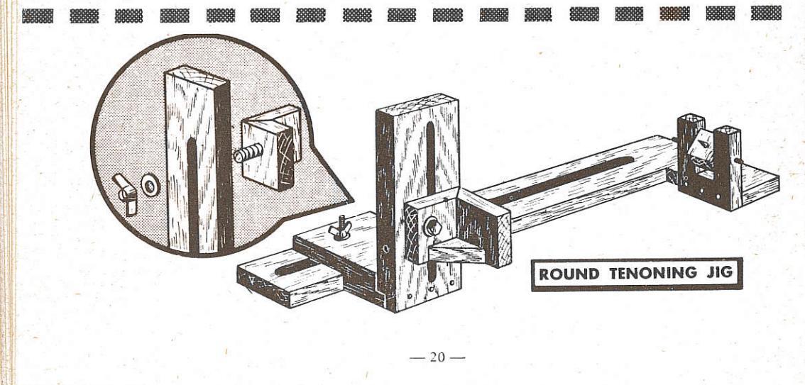
ROUNDING AND TAPERING SQUARE
Perfect round and tapered-round cuts (such as round and tapered-round tenons) can be quickly cut on the bench saw. A fixture like the one illustrated, and a dado head, are all that are needed. The fixture is designed to be clamped to the saw table, and to hold round or square stock as in a lathe. One end of the fixture is adjustable horizontally, so that the fixture will hold different length workpieces, and is also adjustable vertically so that one end of the workpiece can be raised up for making taper cuts. The other end is swivel mounted on a horizontal axis so that it can turn whenever the adjustable end is raised up. The bed piece is cut out to fit over the dado head.
To use the fixture, first mount the workpiece in it as in a lathe, with the end (or middle area) that is to be rounded at the nonadjustable end of the fixture. Locate the fixture over the dado head with the center line of the workpiece exactly above and parallel with the axis of the dado head, and the area in which the first cut is to be made directly over the dado
head. Clamp fixture to table in this position Now start the saw and raise
Now start the saw and raise the dado head up slowly (especially if a square workpiece is being rounded), until it cuts into the wood about 1/8 to 1/4 inch maximum. Rotate the workpiece by hand to cut it all around. Then raise up the
dado head another 1/8 to 1/4 inch, and repeat the cutting process. Continue this until full desired depth of cut is reached.
If a cut longer than the width of the dado head is required, move the fix-
ture over and repeat the above process. The fence can be used to locate the fixture and help keep it square with the blades. When so used, it will also help to fix the amount of fixture movement needed to position additional cuts.

To cut tapered round tenons or sections, raise the adjustable end of the fixture to position the workpiece at the desired angle of taper with respect to the saw table. If tapered end is to be pointed, cut wood nearly through (as when using a lathe), then finish the cut with a knife.


THE SET-UP
A dado insert with a 1-1/8-inch wide slot will accomodate the moulding cutter head. You can also make an insert from plywood — and, if close work with narrow knives is to be done, a specially made insert that will give support to the work right up to the knives will be helpful. The cutter head is installed in place of your regular blade — and need not be removed to install various cutters (instructions are furnished with each head).

If you do not have a shaper fence you can easily adapt your regular fence to shaping operations. Make two 1-inch (thick facings to fit your fence.
Straight-grained hardwood is best. Clamp one facing to the fence on top of a 1-inch thick scrap board — then use a set of planer knives in the head to cut a semi-circular notch in the bottom edge of the facing for knife clearance. Prepare the other facing in like manner, and mount the two facings on opposite sides of your fence with countersunk bolts and nuts.

the moulding head
SELECTING YOUR PATTERNS

Hundreds of designs can be cut with a small selection of knives by combining the cuts of two or more different knives. The cuts can be planned to overlap, to just meet, or to be separated by uncut wood. To help you plan designs, keep a file re-
cord of your knife shapes. Use 4-inch squares of vellum or tracing paper — and make ink outlines of your various knives. Two or more papers can then be stacked together and moved around so that, when you look through them, you can see the results of different knife arrangements. Whenever you select a design for use, trace the composite design on a clean piece of paper, outlining each knife cut, and indicate by numbers the knives to be used. You can then easily duplicate the design at any time.
MOULDING STRAIGHT EDGES
Work is fed to the moulding head in same manner that it is fed to a saw blade, except that the moulding fence is always used as a guide, even when moulding end grain with the aid of the miter gage. Sometimes, especially when work must be placed on edge, it is desirable to move the fence back so that cutting operation is on side of work away from fence. This is less desirable than
cutting along edge next to fence, however, as variations in the thickness of the work will cause imperfect results.
Avoid cross grain moulding as much as possible because it is difficult to keep from splintering the end of the cut. If work is moulded all around, make the two cross grain cuts first, then splinters will be cut off when making the with-grain .cuts.
STRIP MOULDINGS
Strip mouldings are often made by edge moulding a sizeable board, then sawing off the moulded edge in as thin a strip as desired. If thin (strip) stock is used, however, it must be fed to the knives through a strip-


ping guide. The guide is grooved to the exact size needed to contain the strip, and the groove is covered as shown. A cut-out is made in the cover for the swing of the knives. This guide is then clamped to the fence, and the strip stock is fed through it to the knives.
CIRCULAR AND CURVED WORK
Circular work can be guided by two triangular blocks clamped to the fence to form a V-groove; or by use of a pivot pin held by an auxiliary arm fastened to the fence. Curved work must be fed freehand: but a mark on the fence or guide to show center of cutter will help to guide the work. To obtain best results, go around the work two or three times. Overcutting is impossible since the knives can only cut as wide as the fence is set.
TENONS AND RAISED PANELS
Straight knives, used in the same manner as a dado head, will cut excellent tenons. When the arbor (or table) is tilted, these same knives will cut the sides of raised panels. Make the cross grain cuts first, as when making a moulded edge all around a workpiece.
CUTTING DOWELS
To cut dowels, select stock that is about 1/32-inch thicker than diameter of dowel to be made. After both sides are cut, dowel can then be broken from stock and sanded smooth. Semi-circular knives are required.
ORNAMENTAL MOULDINGS AND PANELS
Mouldings and panels can be made by using an auxiliary extension clamped to the miter gage. This fence holds a guide pin so positioned that it will locate in the previous cut to stop the work at the proper place for the next cut. (Operation is same as in making box joints, page 24.) If miter cuts are to be made, pin must slant also. By cutting and crosscutting with different knives, a great many patterns can be made.

Quick spiral turnings on round stock can be made as follows: Make set up as shown, using an auxiliary extension on the miter gage and a standard saw blade. Angle at which gage is set will determine length (pitch) of each spiral, the pitch be-


coming less as angle is increased. When work is held lightly and fed along fence, the blade will revolve it and advance it to cut a spiral groove that will be surprisingly near to accurate. A pin put into the fence can now be used to ride in the groove and guide the workpiece for further cutting with moulding knives. Select a knife that will rout out the width spiral you have prepared, and adjust the fence to obtain the pattern of cut needed. Feed work along fence (guided by pin) to rout out the spirals. Round off rough edges with sandpaper, or rasp file, by hand or by using a lathe.
COVE-CUTTING, JOINTING AND PLANING
A series of overlapping semi-circular cuts will form a smooth straight cove when fence is used to position the cuts. Jointing is done with boards on edge; planing is a series of parallel, light cuts with straight-edge knives.
- 22 ---


CUT-OFF WHEELS
Abrasive cut-off wheels are thin, but strong discs of bonded abrasive. Several different types are available, each intended for use with certain classes of materials. When properly used, these wheels make the circular saw a very useful tool for cutting sheet metal, rods, angle irons, bricks, stones, plastics, glass and many other items.

MOUNTING WHEEL AND FEEDING WORK The wheel should be mounted to the arbor with blotting paper washers at either side, if washers are not already glued to it. It is used in much the same manner as a saw blade, except that work should be fed into the wheel with steady, firm pressure. Too slow a feed permits the wheel to glaze. Glazing is the chief cause of wheel breakage. Too fast a feed will tear abrasive grains away from the wheel before


these have accomplished full duty, and will shorten the life of the wheel.
Always wear goggles or a face shield use the saw guard, if possible.

It is advisable, as a rule,
to clamp the workpiece to the guide being used, to keep the feed accurate and avoid putting stress on the wheel. Many of the materials that can be cut become hot some distance from the cutting point, making it necessary to clamp the work and hold onto the guide. The cut-off board (page 13) makes an excellent guide for round stock; so does the V-block and clamp illustrated.
The wheel is run dry at the regular saw speed. Shapes up to one-inch thick can be cut in one pass; larger shapes are generally cut by "walking" around the cut, if this is possible. Do not expose more of the wheel than necessary. If metals discolor from the heat, remove the discoloration with sandpaper or steel wool.
TRUEING WHEELS
Wheels should be balanced and have clean edges to do accurate cutting. If a wheel becomes out-of-round or chipped, hold an abrasive stick or grinding wheel dresser against the edge (as shown), while saw is running, to true it.

GRINDING WHEELS
Grinding wheels of 1/4-inch to 3/4-inch thickness, depending upon size and style of saw, can be used on bench saws. Because of the many fine adjustments possible
with the better bench saws, these wheels are excellent for a number of precision grinding operations. They are especially adaptable to tool sharpening.

A 1/4-inch thick sanding plate can be mounted on nearly all types of bench saws. Abrasive
discs or sandpaper of any desired grit can be glued to either side of the plate with a quick setting cement. Such a setup is very useful for precision sanding work of all kinds.

CUT-OFF WHEELS ARE FLEXIBLE - CAN BE TWISTED. BUT THERE IS DANGER THEY WILL BREAK IF TWISTED TOO FAR.
- 23 -
1. Single Miter, Flat
2. Single Miter, On Edge
Single (square) miter joints are cut with the miter gage set at 45 degrees, or with a miter board (page 17). Cuts must be exact for a neat fit. The "on edge" miter can be cut, also, as a 45-degree bevel.
3. Polygon Miters
Mitered angles of less or more than 45 degrees are cut by setting the miter gage at the correct angle; or by use of a specially prepared miter board. (Adjustable miter
boards can be purchased.) To find angles of polygons: Divide 180 by the number of sides; then subtract this figure from 90. Answer is gage setting in degrees.

| OLIO | GLES | |||
|---|---|---|---|---|
| THREE | SIDES | = | 30. | DEGREES |
| FIVE | SIDES | = | 54. | DEGREES |
| SIX | SIDES | = | 60. | DEGREES |
| SEVEN | SIDES | = | 64.3 | DEGREES |
| (APPROX.) | ||||
| EIGHT | SIDES | 67.5 | DEGREES | |
| NINE | SIDES | = | 70. | DEGREES |
| TEN | SIDES | == | 72. | DEGREES |
4. Compound Miter
This is a combination miter and bevel cut The bevel angles for some commonly used tapers are given in the illustration. Amounts of taper shown for one foot can be divided by two to obtain amounts for six inches, or multiplied by two to get amounts for two feet, etc.

5. Slip Feather Miter
fferent wood join
To groove a mitered corner so that it will take a slip feather, clamp the two workpieces together onto a tenoning jig. The slip feather (a triangular wedge) is glued into the groove, to reinforce the miter joint.

6. Splined Joint
On-edge miters are often joined with a spline to give added strength. The spline added strength. The spine can be metal or wood, and should run the full length of the joint. To cut the spline grooves, keep the saw tilted at the same angle used to cut the bevel (or miter)


but move work around from the right to the left side of the blade. The groove should be closer to the heel than to the point of the bevel edge, and should not be too deep.

7. Box Joint
A good strong joint for small boxes. Use a dado head approximately the same thickness as the wood. Prepare a guide fence by edge cutting a suitable board, as illustrated. The two cuts are made with the dado head, and are exactly the same distance apart as the width of each cut. Line "A" is at the center of the first is at the center of the first cut, and line "B" is centered between the two cuts. Fit a square peg into the second cut to serve as a guide. Se cure the guide fence to the miter gage in the position in which the fence was placed to make the first cut.


To start the box joint, place both boards against the guide fence, having the edge of one in line with line "A" and the edge of the other in line with line "B". Make the first cut (through both boards). Now move both boards to the right to engage the groove just made over the guide pin, and make the second cut. Continue to move boards one notch at a time and make cuts until joint is finished.
If the guide fence is fastened to the miter gage so that it is adjustable, and the first cut is made large enough, the same set up can be used for various size box joints. When setting the
fence, adjust it so that the distance between the guide pin and side of dado is the same as the width of the dado. Guide pin should be small, and boards are pushed to the right against it each time when lining up the nevt
- 8. End Lap Joint
- 9. Tee Lap Joint
- 10. Middle Lap Joint
These "halved" joints can all be cut with a dado head, or the end lap pieces can be cut in the same manner as a trunnion. If a dado head is used, the first piece is shallow conter per


This block must be the same width as the second piece, minus the width of the dado head. Insert this block between a stop on the miter gage and the end of the piece being cut, to fix the width of the cut to be made. Depth should be exactly one-half thickness of thinnest board.
11. Middle Lap on Edge with Groove
To make each cut in the grooved board, set the dado head to the thickness of the other board. Cut the two grooves first, each ap-proximately 1/5 to 1/4 the thickness of the board. Depth of both edge cuts is exactly 1/2 width of other board; and thickness of cut in second board is exact width of wood remaining between the two grooves of the first board This is a steady joint for a shelf held by two sides which are not strongly braced.
12. Simple Mortise and Tenon
The tenon can be cut with a dado head (page 19) or in several ways with a standard blade (page 17). The mortise is generally cut with a mortising chisel on the drill press.

30 different wood joints (cont'd)

13. Bare Faced Tenon
This type of tenon has just one cheek. It is generally used when a narrow board is joined to a thicker one, as in joining table skirt pieces to the legs.
14. Haunched Tenon
This tenon is often used for joining a piece with grooved framework. The haunch is just long enough to bottom in the groove, and is cut out after the tenon is formed.
15. Concealed Haunched Tenon
The concealed haunch provides extra strength without showing a break at the end (as in the case of the haunched tenon). To make the groove for the haunch, clamp the wood at an angle to the drill press table, and cut the groove before cutting the mortise.
16. Long and Short Shoulders Tenon
This is a single tenon with a rabbet cut out of the shoulder at one side to mate with an edging on the other board. The rabbet cuts made in the two boards are equal in depth.
17. Open Mortise Tenon
This is used in rough box work when the additional strength of a simple tenon is not required. The mortise for this joint can be quickly cut with a dado head.
18. Wedged Tenons
Both the through wedged tenon (illustrated) and the blind wedged tenon (for which the mortise is not cut through) are simple tenons with wedge slots added. As shown, wedges should be slightly bowed at one side instead of straight tapered; and the mortise must be flared out at each end. The flare at each end should equal the maximum thickness of one wedge minus the thickness of one slot.
19. Moulded and Rabbeted Tenon
This is a simple mortise and tenon joint formed in two boards having edge mouldings. Each moulding is miter cut at a 45-degree angle. To start these miter cuts, measure back from the inside edge of the mortise (or tenon) a distance equal to the vertical height of the moulding above the board, and make a mark. The saw should enter the wood adjacent to this mark, on the side nearest the end of the board.
20. Mitered Tenons
The ends of these tenons are cut with a 45degree bevel so that they form a miter joint inside of the mortised piece. Tenons should be formed a bit longer than necessary, to allow for the saw kerf when cutting the bevels. Mitered ends are useful when the tenons are necessarily short and thick.

21. Dado Box Corner
This is a simple joint quickly made with the dado head. Often used to fit the back of a drawer to the sides, it should be made with the dado groove narrower than the rabbet cut.
22. Milled Dado Box Corner
This is used when it is desired to expose the cross grain edge at the side instead of at the end. If the two grooves and the end lap are all of about equal thickness.
all of about equal thickness, a very strong point is provided. A weaker, but never appearing joint is obtained by making the end lap very thin.
23. Lock Miter Joint
This combines the appearance of a perfect miter corner with the strength of a dado corner. The grooves are cut first, then the miters (as shown in illustration).

24. Rabbet Miter Joint
To make this standard saw blade joint: First, cut the two 45-degree miters, cutting the end entirely off the first board, but only cutting into the second board to a depth equal to half the thickness of the first board. Then cut a rabbet in the first board that is as wide (measured from tip of mitered end) as the second board and half as deep as the first board. Take out the wedge already started in the second board by the partial miter cut made at the start.
25. Housed Dado Joint
This is a firm, easily made joint for seating shelves in end pieces. It is quickly cut with a dado head.
25. Cogged Joint
Reinforcing strips are often fitted to main frame members by means of this simple joint. The groove, generally placed in the reinforcing strip, is quickly cut with a dado head.
27. Dovetail Dado
Because of the straight bottom, shelves mounted by means of this joint will carry more weight than if mounted by means of a full dovetail ioint: but will lock in place
just as well. The mortise is cut with a dado head set to the narrowest desired width, then routed out on the top side with a dovetail router guided by the edge being formed. A beveled rabbet forms the tenon.
28. Simple Glue Block Joint
The simplest way to joint two boards at right angles is to cut a rabbet in one board, as illustrated. Such joints are generally reinforced by nailing the boards, or by adding triangular glue blocks, as shown.


29. Lock Joint
This makes a very firm joint in all directions. All of the cuts necessary can be made with a dado head. The order in which cuts should be made is shown in the illustration. Allow just a little freedom between the tongues and grooves, as the two boards must be assembled by sliding them together.
30. Tongue and Groove Joint
This is the commonest type of joint for flooring and siding. The groove is cut with a dado head, and the tongue can be cut either with the dado head, or like two ordinary rabbes. Boards will slide together easiest if the edges of the tongue are slightly rounded off.


The radial saw affords an exceptionally fast, convenient, and accurate method of making bevel, miter and compound miter crosscuts in lumber. It is extensively used in building construction and production woodworking; but also is a very useful tool for small shops doing varied work. All cutting is done through the top of the work. This has the obvious advantage
of making it easier to follow a marked line (as in pattern cutting). Though its principal use is for crosscutting, it can quickly be adapted for rip cutting, shaping, routing and sanding operations.
As with the bench saw, exact adjustment of the saw must be made to obtain accurate work.

First, level the table — by means of the adjustable tabletop supports. It is level when the blade will just touch any point on the table, when lowered sufficiently.
The arm (miter) settings are next adjusted. Block the blade to an exact 90° angle to the table front fence and adjust the 90° stop — and the pointer of the miter scale. Block the blade at an exact 45° angle to the fence to set the two (right and left) 45° stops.

The trunnion is adjusted by setting two bumper stops, one to stop trunnion movement at the crosscut position, the other for the rip cut position. Both adjustments are made by blocking the blade accurately at these respective positions. There is a second scale and pointer on the yoke — to read bevel angles. This is adjusted by blocking the blade at a 90° angle to the table top. The yoke also contains a 45° stop pin (for quick setting of a 45° bevel) — which is adjusted by blocking the blade at a 45° angle to the table top.
- 28 -
OPERATION OF THE SAW
Crosscutting
Straight crosscutting is done with the yoke a. 0°. Depth of cut is set by raising or lowering the blade — then all the clamps except the arm clamp are made tight. The saw handle is used to pull the blade through the work. Miter cross-cutting differs only in that the arm is set to the desired miter angle instead of at 90°. Bevel crosscuting is done with the saw at the straight crosscut position and the yoke (only) tilted to the desired bevel angle. By setting the arm at a miter angle and the yoke at a bevel angle any compound angle desired can be cut.
When crosscutting, the saw should always be started while in back of the front fence — and should be returned there before the work is removed. Never feed work to the (stationary) blade for crosscutting as the blade will "hog" the work unless it is against the fence.
Ripping
Straight rip cutting is done with the arm at 90°, the trunnion at the rip-cut stop position, and the yoke at 0°. Depth of cut is set as in crosscutting — and the distance of the cut out from the fence is set by pulling the saw

out, then locking the arm. Tighten all clamps and feed work to the blade along the fence from your left to right (never from right to left). Use the anti-kick-back plate to hold work down. Bevel rip cuts are made by varying the yoke position — and taper rip cuts are made with a taper ripping jig (page 12).
OTHER OPERATIONS
Dado and groover saws, sanding discs, and a moulding cutter head can all be used the same as with a bench saw. In addition, the radial saw head can be positioned with the arbor vertical (like a drill press) by tilting the yoke to 90°. This makes the saw useful for routing, drum sanding, surfacing (with a surface-planer), and for accurate tongue and groove cutting. Special adapters to hold these various tools are available — and also left-hand cut router bits (standard right-hand cut bits won't work). Tenoning (tongue cutting) is done by using special spacers to separate parts of a dado set so that both sides of the tongue can be cut simultaneously.
In all vertical arbor operations the saw can be pulled through (as for crosscutting) — or can be locked so that work can be fed along the fence or a jig guide. It is important to remember, however, that in this position the arbor rotation is reversed — work fed along the fence must be fed from your right to left.
The swing saw is primarily a heavy-duty straight and miter (no bevel) cut-off saw — which can also be used for ripping. It consists of a beltdriven blade (with the motor) mounted on a vertical yoke to which a pendulum-like swing is imparted by the operator, by grasping a handle at the side of the blade. This yoke is swivel mounted at the end of a radial arm and may be pivoted to turn the blade, in either direction from the crosscut (0) position, to any miter angle desired, up to 90°. Angles are indicated by a scale and pointer at the top of the yoke. A handled catch secures the yoke at the crosscut and rip (90°) positions. The radial arm may also be pivoted on its supporting column, and may be raised or lowered on the column by an elevating screw — when the clamp is released.
Because of the simple controls this saw is very quickly adjusted to make a cut, and very easy to use. The only accuracy check required is to block the blade at a true 90° angle to the fence, and re-set the miter-angle pointer to "0", if necessary. Straight or miter cross-cutting is done by holding the blade back toward the column, placing the work on the table up against the fence — then swinging the blade forward through the work. Ripping is accomplished in exactly the same manner as with the radial saw. Dado and groover saws can be used. For safety, never use the saw without the saw blade guard.

SELECTING A HAND SAW
Used primarily for "on-the-job" sawing of the kind otherwise done with a hand saw, the power hand saw can be a real labor saver. It may be used for sizing lumber prior to construction and for trimming off the uneven ends of boards and forms after these have been nailed in place. This latter use will often eliminate much measuring and fitting, and greatly speed your work.
Well-designed saws provide guides for cutting straight lines, whether ripping or crosscutting, or when saw is at 90° or tilted to cut a bevel. They also provide an adjustable depth of cut and adjustable angles from 0° to 45° for bevel cutting — and are equipped with a movable saw guard (with blade at right, away from operator), a convenient in-handle, squeeze-"On" type switch, and large comfortable handles for one- or two-handed operation. The blades are designed for rip or crosscutting — and may be replaced by abrasive discs for cutting cast iron, concrete, tile, stone and similar materials. Modern, compact construction assures a light-weight, easily handled tool.
An 8-inch saw (which cuts 27/8 inch deep at 90° or 17/8 inch deep at 45°) should have a 1 hp motor, while a 61/2 inch saw (2-3/16 inch deep at 90°, 1-11/16 inch deep at 45°) needs a 3/4 hp motor.
SET-UP AND CARE
NOTE: Not all saws have the adjustments referred to in the following in-
Connect the saw cord with a 115 volt a-c or d-c source. If an extension is used, it should be 12 gage or larger up to 75 feet, 10 gage or larger up to 125 feet. A too small extension will result in too low a voltage at the saw. Low voltage can result in overheating and motor burn out. Make certain voltage used agrees with nameplate rating! Use the Ground Connection, too — especially if working in a damp place.
Lubricate regularly, as instructed by the manufacturer — keep inlet and outlet air passages clear to assure proper cooling (use an air jet, if necessary) — and, above all, keep the blade sharp, clean and properly set.
OPERATING ADJUSTMENTS Installing A Blade
The blade (or abrasive disc) is mounted on the shaft between the thimble and shaft washer and held by a hex-head clamp screw (which must be tight). Make certain the blade teeth point up at front of saw. Measure from each edge of blade to nearest point on edge of base plate. If distances are unequal, straighten base plate by tapping it with a block of wood.
Depth Of Cut Adjustment
Loosen Locking Handles A and move the base plate up or down until blade projects the desired amount. You can measure down from the base plate bottom with a ruler to make an accurate setting — but it is generally best to let the blade project a little more than the thickness of wood to be cut. Tighten handles.
Bevel Cut Adjustments
Angles less than 25° can be set with the base plate in highest position; but for greater angles the plate must be lowered (as above). Loosen Locking Handle B and tilt the plate to the desired angle, as read on the Protractor Scale. Tighten the handle.

PROPER OPERATING PROCEDURES
Before pressing switch, rest the front of the base plate on the work — then squeeze the switch and let blade come up to full speed before starting to cut. Allow blade to cut its way through wood without forcing. Forcing results in inaccurate work and, overloading of motor. If blade slows, back it out and restart. If motor stalls, do not release switch — back out and let blade run free first. Guide with one or both hands.
To crosscut, follow a line on the work. The Beveled Guide Edge is exactly in line with the saw blade when blade is set at 90° or 45° —
- 30 -
and can be used as your guide. At other blade angles the blade will be up to 3/64 inch to the right — and it is better to use the Graduated Scale as a guide by drawing a line (on the work which is offset to the left of the desired cutting line by the amount blade has moved to the right of the Beveled Guide Edge. Be careful to prevent blade from binding in the kerf at end of cut.
To rip, either use procedure above or use the Rip Guide — by setting the desired cut on the graduated scale of this guide, using the right (blade-side) edge of the Protractor bracket as your index. Right edge of work must be true for Rip Guide to follow it.
Pocket cuts can be made by swinging the guard up out of the way, resting the front edge of the base plate on the work — and slowly lowering the blade into the work while running. For safety, leave the guard down for all other cuts.
USE OF SAW GUIDE
This guide converts your saw into a portable, efficient tool with which you can cut bevel, miter and compound angles. For use, mount it on a plywood base as illustrated.
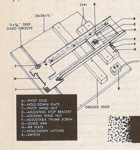

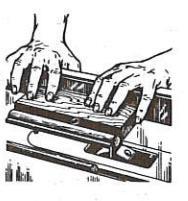
For radial-saw type cut-off use, position the Guide Arm at 90° to the fence (long 2x4) and finger tighten the Pivot Wing Nut. Check with a square between the edge of the Guide Arm and the fence — and adjust to exactly 90° using the Adjustable Thumb Screw which is secured by the Locking Wing Nut. Raise the saw guard and position saw in Saw Guide. Lower blade to groove the table top about 1/8 inch. Slide work into position from your left and hold it securely against the fence with your left hand — then start saw and push it through the work.
For miter cuts proceed as above, but pull the Guide Arm back to clear the Adjusting Stop Bracket if you want to swing the rear end to your left. The Adjustable Thumb Screw cannot be used — set your desired angle by using a protractor instead of a square (as above).
For bench saw use, secure the saw base plate to the Rip Plate with the three Hold-Down Latches. Position the blade any desired measured distance from the fence, and tighten the Pivot Wing Nut. If the Adjustable Thumb Screw was properly set for radial-saw use, and is still against the Guide Arm — the blade will be exactly parallel to the fence. Lower blade to just nick table top. With a block of wood inserted under handle to hold switch closed, your saw can now be used for ripping or (with Miter Gage No. 9-2246) for crosscutting — just like any bench saw.
power hack saws
For anyone who must do on-the-job pipe, barstock and similar metal cutting, a power hack saw — that will cut while you work — is a great time and labor saver. Top quality tools have an automatic relieving mechanism to lift the blade from the work on the return stroke, and can be positioned for cuts at any angle from 90° to 45° The built-on vise has a quick-locking feature and (in the saw illustrated) a maximum opening to take 4 by 4 inch work. Operated at 60 strokes per minute, this model requires a 1750 rpm motor with 11/2-inch motor pulley — takes a standard 12-inch blade.

tables
| TILT AND MITER-GAGE SETTINGS FOR COMPOUND ANGLES | |||||||||
|---|---|---|---|---|---|---|---|---|---|
| ANGLE |
Sides
Butt Joint |
Sides
Miter Joint |
6 Sides
Miter Joint |
P |
8 Sides
Miter Joint |
||||
| Work Angle |
Tilt
Table |
Miter
Gage |
Tilt
Table |
Miter
Gage |
Tilt
Table |
Miter
Gage |
Tilt
Table |
Miter
Gage |
|
| 5° | 1/2 | 85 | 44 3/4 | 85 | 293/4 | 87 1/2 | 221/ | 8.8 | |
| 10° | 1 1/2 | 80 1/4 | 44 1/4 | 80 1/4 | 29 1/2 | 84 1/2 | 22 | 86 | |
| 15° | 3 3/4 | 75 1/2 | 431/4 | 751/2 | 29 | 81 3/ | 211/2 | 84 | |
| 20° | 61/4 | 71 | 42 | 71 | 281/4 | 79 | 21 | 82 | |
| 25° | 10 | 67 | 40 | 67 | 27 1/4 | 761/2 | 201/ | 80 | |
| 30° | 14 1/2 | 63 1/2 | 37 3/4 | 63 1/2 | 26 | 74 | 191/ | 781/ | |
| 35° | 19 1/2 | 60 1/4 | 351/4 | 60 1/4 | 24 1/2 | 713/ | 181/ | 763/ | |
| 40° | 24 1/2 | 57.1/4 | 323/ | 57 1/4 | 223/ | 60 3/. | 17 | 75 | |
| 45° | 30 | 54 3/4 | 30 | 54 3/ | 21 | 673/ | 153/ | 731/ | |
| 50° | 36 | 521/2 | 27 | 521/2 | 10 | 661/ | 1 4 1/ | 73% | |
| 55° | 42 | 50 3/4 | 24 | 50 3/ | 163/ | 6431 | 123/ | 71 1/2 | |
| 60° | 48 | 49 | 21 | 49 | 14 1/2 | 63 1/2 | 11 | 701/4 | |
| ELCUIDEC ADD | IN DECOR | and the second second | |||||||
FIGURES ARE IN DEGREES AND ARE FOR DIRECT SETTING TO TILT SCALE AND MITER GAGE SCALE PROVIDING TILT STARTS AT 0° AND MITER GAGE AT 90° IN NORMAL POSITION.
| all'aderes | BEVELS AN | ND MITERS | State And State | ||||
|---|---|---|---|---|---|---|---|
| Figure | Sides |
Ripping
(Tilt Table) |
Crosscutting
(Set Miter Gage) |
Figure | Sides |
Ripping
(Tilt Table) |
Crosscutting
(Set Miter Gage) |
| Triangle | 3 | 30° | Octagon | 8 | 22.5° | 67.5° | |
| Square | 4 | 45° | 45° | Nonagon | 9 | · 20° | 70° |
| Pentagon | 5 | 36° | 54° | Decagon | 10 | 18° | 72° |
| Hexagon | 6 | 30° | 60° | Undecagon | 11 | 16.62° | 73.38° |
| Heptagon | 7 | 25.83° | 64.17° | Dodecagon | 12 | 15° | 75° |
| DIAMETER | ARBOR |
|---|---|
| OF SAW . | SPEED |
| 6 | 6300 RPM |
| 7 | 5400 RPM |
| 8 | 4700 RPM |
| 10 | 3800 RPM |
| 12 | 3200 RPM |
|
Thickness
of Work |
Thickness
of Tenon |
Corresponding
Mortise |
|---|---|---|
| 3/s inch | 1/8 inch | 1/2 inch router bit |
| 1/2 inch | 1/s inch | 1/s inch router bit |
| 3/4 inch | 1/4 inch | 1/4 in. hollow chisel |
| 7∕8 inch | 1/4 or To inch | 1/4 or 15 in. chisel |
| 1 inch | To inch | To in. hollow chisel |
| 1 1/8 inch | 3/8 inch | 3/8 in. hollow chisel |
| 11/4 inch | 3% or To inch | 3% or To in. chisel |
| 1 1/2 inch | 1/2 inch | 1/2 in. hollow chisel |
| 1 3/4 inch | To inch | 3/s in. chisel (two rows) |
|
hes
e are max
maller is ofte zes. |
imum tenon this
n satisfactory, |
cknesses. The next siz
especially in the large |
- 32 -


give you complete, up-to-the-minute instructions for set-up, adjustments and proper handling of each tool — including hundreds of standard operations, short-cuts and special operations. All fully illustrated and described. Ask for these handbooks:
- The Circular Saw
- The Drill Press
- The Wood Lathe
- The Jig Saw and Band Saw
- The Jointer. Shaper and Thickness Planer
- How to Sharpen
- Power Tools How to Use Them
AVAILABLE AT ALL SEARS RETAIL AND MAIL ORDER STORES


 Loading...