


INDEX
| THE JOINTER | 33507 |
|---|---|
| GENERAL INFORMATION | 2-3 |
|
Usage — Selection — Controls — Too
— Accessories. |
d Bench |
|
SET-UP AND ADJUSTMENTS
Mounting — Cutter Head — Cut Por Toble Adjustment — Fence Angle Por Cutter Knives. |
|
| OPERATION | |
|
STANDARD JOINTER OPERATIONS
Surfacing — Edge Jointing — End Join Squering & Boord — Toper Jointing — Toper: — Compound Topering — Stoppod |
57-10
Iting |
| Bevel Jointing - Robbetting - Round | Tenons. |
| THE SHAPER | |
| GENERAL INFORMATION | 12 |
|
OPERATION AND ADJUSTMENTS
Controls — Adjusting Fence — Adjust Hold Down Engers |
13
Ting |
|
GENERAL SHAPER OPERATIONS
Set-Up — Curter Combinations — Fee Week — Square Steck — Holding Fist Three General Methods Used for Shap Shaping with Guides, Collors, and Po |
|
| USE OF GUIDES | 16-17 |
|
Fences — Foce Shaping — Guides — S
Fixed Fuch Shae. |
lops — |
| USE OF COLLARS | Block. |
|
USE OF PATTERNS AND FORMS.
Planning Patterns — Double Patterns — P a Bavel — Doubling Up Patterns — Sild Strip Shaping Jig — Prot Jig — Rank — Holding Jig — Rocking Jig — Tanon — Bavel Jig — Pluting Jig — Rankbi Soth and Door Shaping. |
.19-23
Sunning Ing and ding Jig Jig |
| MISCELLANEOUS SHAPER | |
|
OPERATIONS
Jointing — Toper Jointing — Ponel Rain |
24-25 |
| Making Dowels Ornamental Designs | |
| THE MOULDING CUTTER HEAD | |
| TTPICAL MOULDING CUTS | |
| THE THICKNESS PLANER | |
|
GENERAL INFORMATION
Usage — Set-Up and Adjustments — Heads and Controls. |
Cutter 28 |
| OPERATION | |
|
General Procedure — Reducing Stock
Thickness — Reducing Square Stock to 1 Planing Thin Stock. |
to
lize — |
| SHARPENING KNIVES AND CUTTER | S30-31 |
| Moulding-Head Cutters. |

Catalog No. 9-2916
SEARS, ROEBUCK and CO.
REVISED 1954


WHY A JOINTER IS NEEDED IN THE WORKSHOP
The jointer is a power tool designed especially to do the work formerly done with a hand plane. Not only will the jointer do the work much faster — it will also do it much better, if kept in proper operating condition. We would like to show you how, with your jointer you can produce the quality of work necessary for craftsman-like cabinet making. Straight and true joints, that will fit together with hardly a visible space between, can easily be produced even by inexperienced workers, if proper care is taken to make the set-ups and perform each operation correctly.
SELECTING A JOINTER AND MOTOR
Jointers are made in a variety of sizes for light, heavy, and special duty work. Well constructed machines are equipped with ball or roller bearings which are enclosed in dust-proof housings — and have tilting fences so that bevel cutting can easily be accomplished. The knives (or cutters) are fitted into a cylindrical head which revolves at a very high speed — generally between 3600 to 4500 rpm. In good quality jointers the head is equipped with 3 knives; but some jointers have only 2, or as many as 4 knives. Those having wider table tops — 6 inch and up — can easily be used for planing
operations as well as for jointing; and even the narrower models can be used for planing small boards. The practical maximum width board which can be planed on a jointer is just under twice the width of the jointer cutter head.
When selecting a motor, be careful not to underpower your jointer. Satisfactory work can not be done at slower than the recommended spindle speeds. In general, a 1/3 or 1/2 h.p. motor should be used for a 4-inch jointer; a 1/2 or 3/4 h.p. motor for a 6-inch jointer; and a 3/4 or 1 h.p. motor for an 8-inch jointer. Manufacturers always specify proper motor capacity and pulley diameters.
OPERATING CONTROLS
Typical controls are shown in the large illustration. The "Handwheel" is used to raise or lower the front table — to vary the depth of cut (which is indicated by the "Depth of Cut Pointer and Scale"). Loosening the "Fence Slide Lock" permits movement of the fence on the slide rail — if (in models having a sliding guard) the "Sliding Guard Knob" is also loosened. The fence is loosened for tilting by loosening the "Fence Angle Locknut," which — in the models illustrated — can be turned by engaging the "Fence Lock Handle" with the locknut. Angle of fence tilt is indicated by the "Fence Angle Pointer and Protractor Scale."

set-up and adjustments

SETTING-UP YOUR JOINTER
Your Jointer should be mounted securely on a stand or bench so that the surface of the table top is approximately 32 inches above the floor — and as nearly level as possible. The motor should be installed below the cutterhead pulley, either on a motor rail or on a wooden shelf which will provide proper belt tension. The motor must drive the cutter clockwise, when the front table is at your right.
GENERAL INFORMATION
Exact adjustments are absolutely necessary if your jointer is to do accurate work. Most late model jointers have a front table which has no separate leveling adjustment — and the cutter head and rear table must be adjusted to a level with the front table. The cutterhead arbor is usually supported (front and
back) by bearing brackets (or journals) which can be adjusted slightly up or down. All jointers have leveling jacks (3 or 4) under the rear table — and in most models these jacks serve also to adjust the rear table height. Actually, only a few very special operations are made possible by having the rear-table moveable. For practical pur-
poses, the rear table should be properly adjusted, and left alone as exact alignment is essential to 99% of all jointer operations. Typical rear table and currer

rypical rear table and cutter head adjustments are illustrated. Make adjustments in exact order as given below.

CUTTER-HEAD ALIGNMENT
Run the front table up as high as it will go. Rotate the cutter head by hand to place one of the knives at its highest position. Place a straight edge on the front table so that it extends over the cutter head. The edge of each knife should just

touch the bottom side of the straight edge as the straight edge is moved back and forth across the table (from end to end of the knife). Loosen the cutter-head-arbor-bearing brackets (if tool is equipped with adjustable cutter head) and adjust cutter head height to accomplish this, if necessary.
SETTING DEPTH OF CUT POINTER
Following the preceding adjustment — and without moving the front table — set the depth of cut pointer exactly at "O" on the depth of cut scale. Either the scale or, in some models, the pointer, can be moved when holding screws are loosened.

-4-
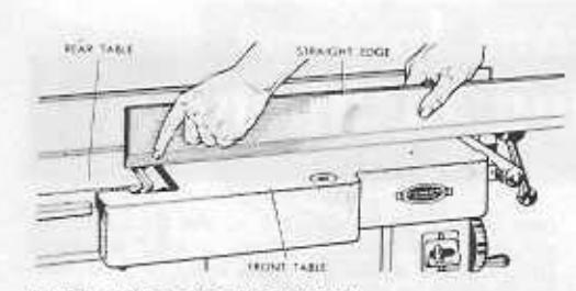
REAR TABLE ADJUSTMENT
Having the rear table too high or too low makes it impossible to make a true cut. Careful adjustment will assure good work.
With front table still all the way up, slide the straight edge to the left until it touches (or is above) the right edge of the rear table. The straight edge should be flat on the front table throughout all of its length — and should just touch the top right edge of the rear table. When moved all the way back (toward the fence) or all the way forward, it should still just touch this edge. If the rear-table edge raises the straight edge up off the front table, the table edge is too bigh at this point; if there is a gap between the straight edge and the rear-table edge, the rear-table edge is too low at this point. Adjust the two leveling jacks under the right edge of the table exactly right.
Now slide the straight edge to the left until it is on top of both tables from end to end of the jointer. If there is a gap between the left end of the rear table and the straight edge, the left end of the table needs to be raised. If the

straight edge rests on the left end of the rear table and there is a gap between it and the right end of the table and or the front table at any point, the left end of the rear table needs to be lowered. Adjust the one (or two) leveling jacks under the left end of the rear table, as required.
SETTING FENCE ANGLE POINTER
Better quality jointers have a tilting fence — and the angle of tilt is indicated by a fence angle pointer and a protractor scale. The pointer should be exactly at "O" on the scale when the face of the fence is at a right angle

to the table top. Use an accurate square to block the fence correctly, then adjust the pointer, if necessary, exactly at "O."
RE-SETTING CUTTER KNIVES
After re-sharpening the cutter-head knives (see page 30), it is also necessary to re-set the knives in the cutter head. This is a very important
operation, and must be carefully done, otherwise your jointer cannot operate properly. Two of the best methods for re-setting the knives are described below.


In method No, 1 the front table is fully elevated so that a straight edge will touch both tables at all points. Install the knives in the cutter head with each knife projecting slightly above the tops of the tables, and with the outer end of the knife projecting exactly 1/16 inch outward from the cutter head. Clamp each knife lightly into position with the set screws and wedge provided. Be sure to engage the points of the set screws in the slots of the wedge.
Now rotate the cutter head by hand to position one knife at its highest point — then tap the knife down with a wooden block until the top edge of the knife is exactly level with the surfaces of the two tables from end to end. Check this with the straight edge — then tighten the set screw securely. Adjust the other two knives in the same manner.
The second method makes use of a magnet, Clamp a block of wood across the front table to act as a stop for the magnet. The edge of this block must be exactly parallel with the
the magnet on the rear table with the two ends butting against this stop block. Insert one knife into the cutter head, and rotate the head to place this knife at its highest

place this knife at its nignest position. The magnet will now draw the knife up out of the cutter head, so that the top edge of the knife is exactly level with the surfaces of the two tables. Tighten the set screws which hold this knife; then proceed to set the other knives in like manner.
Whichever method is used, the net result must be that all knives are set so that the highest point of each is exactly level with the two table tops (when front table is all the way up).
NOTE
Although most jointers are shipped with all necessary adjustments made at the factory, rough handling in shipping may cause slight maladjustments. It is important, therefore, to check ALL adjustments before using a new jointer, on order to insure the high quality work for which it is intended.
general operating instructions
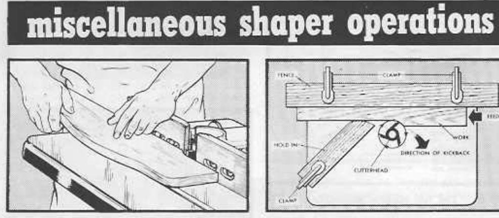
CORRECT HAND POSITIONS
In determining hand positions, two things must be kept in mind: 1) The fingers must not be allowed to pass dangerously close to the revolving blades; 2) The work must be kept in solid contact with the table tops, if a straight true cut is to be made.
In general there are two methods of accomplishing this.
First, and quickest, is the "follow through" method. The hands are placed on top of the work so that the left hand
will be above the front edge of the rear table just as soon as enough of the work has
- and is used to press the work firmly down on the rear table to obtain a true cut. As the work progresses, the left hand is moved backward along the work so that it will remain approximately above the front edge of the rear table. The right hand is placed on the front edge
of the work where it can be used to simultaneously hold the work down on the front table and to push the work forward across the knives. It remains in this position on the work until the cut is completed — and therefore passes directly over the knives as the back end of the work is finished. When using the hands thusly, care must be raken to pull the thumb upward to a safe height above the knives as the right hand passes over the cutter head.
The second method is best when surfacing boards, especially thin boards — and does not require either hand to pass over the knives. At the start, both hands are kept on top of

that part of the work which rests on the front table. When enough of the work has passed onto the rear table, the left hand is lifted up and moved through the air to rest on top of the portion of the work now on the rear table. Similiarly, as the front edge of the work approaches the cutter head, the right hand is also lifted and moved to the
rear table. As in the case of the first method, the left hand is used entirely to hold the work firmly down while the right hand is used both for holding the work down and for propelling it over the knives.
Special hand holds are required when jointing the edge of a very wide board, or when jointing the end of a board which will project twelve or more inches upward from the table. Obviously, support must be
given to the board to keep it from rocking to the right or left—and the left hand is therefore used principally to push the board over against the fence to keep it squarely upright. If the board extends high enough above the table, the weight of the board will hold it down, and the right hand can be used principally to propel the board over the knives; otherwise, the right

hand should be on top of the board to be hold it down and propel it.
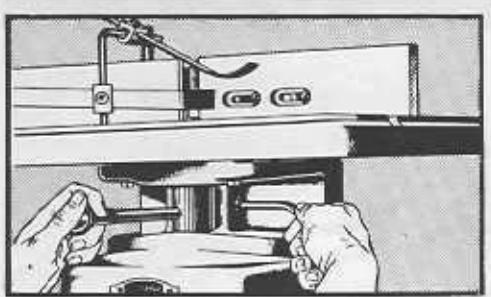
MAKING AND TESTING A CUT
Unless a special operation requires otherwise, always cut with the grain of the wood — as illustrated. If necessary to cut against the grain, move the workpiece at about one-half normal speed across the cutter head, and slow down even more when approaching the end of the workpiece. This will prevent the knives from splitting the end-of the workpiece.
Edge or rabbet cuts up to 1/2-inch depth can be made
on a 4-inch jointer — but best results are obtained with maximum cuts of 1/8 to 3/16-inch deep, and by making successive cuts to obtain greater depths.
The depth of a cut that is made can be accurately measured, prior to completion of the cut, as illustrated.
When it is necessary to make a single deep cut, feed the work at a slower rate than normal to keep from slowing down the cutter head. If the cutter head slows down too much, the cut will be very rough.

TESTING DIPTH OF CU
standard jointer operations
SURFACING
General Set-Up
Adjust the front table so that about a 1/32-inch cut will be made. The depth of cut can be
Set the fence at a right angle to the surfaces Set the rence at a right angle to the surfaces of the two tables. Generally speaking, the ing the work across the cutter head, using the hands as already explained on page 6. Before
Boards With Warp and/or Wind
Warped lumber is dished from side to side across the board. Such workpieces are preferably surfaced on the
dished or concave side as the two edges of the board will rest on the table ton ing. Whenever it is pecessary and on to surface the convex side hold the work firmly to preing over the cutter head. In

either case, make a sufficient
number of basses over the cutter head to reduce the work to a flat surface.

Wind is a twisting of the workpiece from end to end. Testing for wind can be done by
board on a flat surface, as illustrated above. When a out of wind it is advisable to mark the work carefully least number of cuts. This

will avoid loss of workning thickness. After cessive passes enlarge the area of cut until in finally takes in the entire underside of the
When it is necessary to hold one edge or one corner of the workpiece up off the table top in order to remove wood from a low corner edge to correct wind, good use can be made of small blocks of wood nailed or clamped to workpiece edges. These blocks should be positioned so that they will ride on up of the tables and guide the workpiece over the

Thin Boards
A pusher shoe which will help you to both propel the work across the cutter and to hold the work down, at the same time, is very handy for surfacing operations. Such a shoe is particularly desirable when surfacing very thin boards, as it keeps the hands a safe distance
A design for a simple homemade pusher shoe is illussurface of the larger block just enough so that it can be hooked behind the end of the workpiece to push it for-

ward. It should not project down far enough to contact the cutter knives when the shoe is pushing the end of the work over the cutter
An even simpler pusher shoe can be constructed by fastening narrow blocks of wood to the top of the large block, in place of the handle and knob. It is only necessary that some means be provided for holding the top of the shoe securely with both hands. The shoe should be long enough to firmly press the work down on the tables, from end to end.

The tops of very thin boards as a will be lower than the bot-tom edge of the fence adincent to the rear table, so as a proper guide. This makes it necessary to use an auxiliary fence when sur-facing such thin boards ------------------------------------
Wide Boards
Boards up to twice the width of the cutter head, lap can be surfaced on your machine. Surof the board over the cutter head, without changing the height of the front table. The ging the neight of the front table. The to surface the other half. One or the other the grain of the wood — and it is generally best to make the first cut in this manner, leav-
Long Boards
Very long boards create a problem because it is difficult to simultaneously handle the unwieldy board, and to press it down properly against the table tops. A hold-down fastened to the fence above the rear table is a great help. Either a wood or metal-leaf spring will serve this purpose. It should be clamped to the fence so that the edge of the board can pass between the spring and the top of the rear table - and so that the spring will hold the board firmly down onto the rear table.
Very Short Boards
Generally speaking, it is not practical to surface hoards under 12 inches in length, because shorter boards do not provide sufficient hand hold leverage to offset the kick-back of the
on top of a short workpiece to propel it over the cutter head. The longer board can either be nailed to the workto "grip" the workpiece.

-8-
EDGE JOINTING General Set-Un
This is the simplest and most common opertion which can be done on the jointer. general, approximately 1/8 inch of material should be the maximum removed in any one pass of the workpiece over the cutter head. suiding the workpiece when jointing — should guiding the workpiece when jointing — should be very carefully set at a right angle to the be very carefully set at a right angle to the table top. The workpiece is held and fed across the cutter head as already explained
Fairly rough edges can be successfully jointed - but it to cut off extremely rough edges on a band or bench saw prior to jointing
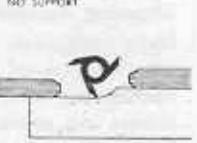
Dished and Bowed Edges
Dished (concave) edges present no great difficulty, if the whole length of the the whole length of the board extends out beyond the front of the front table however an auxiliary support must be provided to the same level with the end on the table. Jointing bowed (convex) edge of a board is difficult because board to rock end-to-end. This is difficult to overcome of support. The best practice of scrap stock to the board, one at each end so that the board will pass over the cutter head on a level plane. If the board is too long for the front block to rest on the table the start of the cut, use an auxiliary table as explained above
Wide Boards
The low fence provided with most jointers is not high enough to properly support jointing — and there is a tendency for the board to wobble from side to side during the operation.
this reason, it is advisable to attach an auxiliary fence to the regular fence - and to have this auxiliary fence high enough so that the workpiece can be pressed firmly against it to pre-
Very Rough Edges
A very rough edge can be successfully jointed if you remember to put all of the "down pres-sure" on that portion of the workpiece which is above the rear table. Do not put any "down pressure" on the end of the work which is on the front table, and which still has an uneven bottom edge.


End Jointing
End jointing is much the same as edge jointing; except that there is a tendency for the wood to split at the back end as this end is passed over the cutter head. For this reason, two cuts - one from each edge of

The board — are generally better than one straight cut. The first cut is long enough to carry past the second or third grain of the wood at one edge. The board is then turned around, and the second cut is made to overlap the first cut and give a straight edge. Do not make the first cut too long, as a sufficient length of the edge to keep the board steady must be left to rest on the top of the rear table while finishing the second cut.
Dished and bowed ends are handled in the same manner as dished and bowed edges. When the board is very long (therefore standing high in the air above the table) it is advisable to provide some means of supporting it without its wobbling. Support can sometimes be provided by a horizontal board clamped to the workpiece and arranged to ride along an auxiliary support placed at the right side of the jointer.
SQUARING A BOARD
The first step in squaring all six sides of a board is to surface one side (preferably the side which is easiest to surface) in order to obtain a "working face." The two ends are then jointed; and afterwards the two edges are
jointed: and afterwards the two edges are jointed. End and edge jointing are done with the working face pressed against the fence so that these joints will be square with the working the square with the working
square with the working so face. The sequence of end and edge jointing steps is for shown in the accompanying illustration.
After jointing the ends and
edges, proceed to surface the remaining face as follows: Cut four small wood blocks of equal length, and glue these to the edges of the board near the four corners in such manner that they will support the board with the working face on top and parallel with the front table of the jointer. These blocks should be just long enough to accomplish this purpose, and should not extend downward below the level of the lowest point on the unsurfaced side of the board. Now surface the underside of the board, making as many cuts as necessary to reduce it to an absolutely smooth surface.


Taper jointing is very useful in making table legs like those illustrated, and for numerous other cabinet making operations.
Straight Tapers
The simplest tapering operation is done with workpieces shorter in length than the length of the front table. Before starting the machine, make a set-up as follows: Lower the front table to

to the cutter head. With the workpiece in the workpiece on top of the front table and against the fence — with the back edge barely resting on the edge of the rear table adjacent to the cutter head. With the workpiece in this position, clamp a piece of scrap wood to the front table so that it will butt up against the end of the workpiece.
After the set-up is made, remove the workpiece and start the jointer. Now place the end of the workpiece against the block clamped to the front table (as it was during the setup), and lower the other end onto the cutter head until portion just behind the cutter head (which will be uncut) rests on the rear table (as in the set-up). Starting thus, advance the work across the cutter head. The uncut portion which was resting on the rear table at the start will hold this end high, so that the resulting cut will be tapered toward the other end of the workpiece. Continue lowering the front table approximately 1.8 inch at a time and make additional cuts in this same manner until the narrow end of the taper is as deep into the workpiece as desired.

If the workpiece is longer than the length of the front table, exactly the same procedure can be used — but an auxiliary extension must be fastened to the front table so that the entire workpiece will have a level surface to rest upon. If the front table is to be lowered for additional cuts, this extension must be lowered also.
A long taper can be cut without an extension. Lay out the taper and divide the area to be tapered into sections, each section several inches shorter than the length of the front table. A first
-9-
standard jointer operations (cont.)
cut will start at the section line nearest the tapered end of the workpiece. This first cut must remove either 1/2, 1/3, etc. of the total amount of stock to be removed from the workpiece end. Each successive cut will remove a like amount of the remainder -and these successive cuts will start at the second, third, etc. section lines and m run out to the workpiece end.

Compound Tapering
A compound taper is made when a taper, at a greater angle than the original taper, is cut at one end of a tapered workpiece. Compound tapers can include two, three or more tapers - each at a greater angle than the adjoining taper.
To cut a compound taper, cut the first taper as already explained - then make a new setup with the stop block arranged so that the workpiece will drop down onto the cutter edge at the point selected for starting the second taper. The second taper can then be cut in exactly the same manner in which the
Stopped Tapers
A stopped taper is one which does not run all the way to the end of the workpiece. This type of cut is widely used in making table legs-a good example of this is illustrated

A stopped taper can be freehand cut by using the same procedure given above for cutting straight tapers. It is only necessary to start and stop the cut at the proper places. For this reason, the best practice is to lay out your plan for the taper on the workpiece, as illustrated above. The starting line (A) should be directly above the highest point of the cutter head (approximately one inch to the front of the rear table front edge) at the start. The stopping line (B) should be approximately above the back edge of the front table at the end of the cut-and the workpiece should be lifted straight up off the cutter head when this point is reached
It will be easier to handle the workpiece if the fence is moved as close to the left edge of the machine as the width of the workpiece will permit. If it is necessary to watch the guide lines, the cutter guard must either be Stop blocks, clamped to the front and rear rables as illustrated, will make it easy to cut uniform stopped tapers on all four sides of one or more workpieces. A set-up must be made before starting the machine-and the blocks should be arranged so that the workpiece will butt against the one on the front table when the starting line (A) is correctly positioned for the start of the cut-and so that the stop block on the rear table will be bumped by the workpiece, when the finish line (B) is correctly positioned for the end of the cut

miscellaneous jointer operations
BEVEL JOINTING
Bevel jointing is done by tilting the fence to the desired angle, as indicated by the fence angle pointer and protractor scale. The fence can be tilted either in or out — as shown in the illustration; but it is much easier

o work with the fence tilted out.
Once the fence has been set to the desired angle, the actual operation is exactly like edge jointing. Taper cutting can also be done with the fence tilted, to produce a beveled taper.
Chamfers — the cutting off of a sharp edge at a bevel — are made in the same manner as beveled joints; but only a small portion of the edge is removed.
RABBETTING
Rabbetts — or edge grooves — are easily cut on your jointer. Move the fence over to the outer edge of the jointer so that you will obtain the desired width of cut when the workpiece is pressed against the fence.

Now make the cut in the same manner used for surfacing. As many cuts as necessary to obtain the desired depth of cut can be made. Also, successive cuts can be made with different fence settings to obtain stepped rabbetts like those illustrated above.
Beveled rabbetts and tapered rabbetts can also be easily cut by combining the technique for rabbetting with the set-ups used for bevel and or taper cutting.
When cutting rabbets in very thin stock, be sure to use a pusher shoe as explained in "Surfacing."
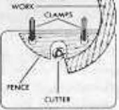
HANDLING SMALL STOCK
When jointer operations on very small stock are being done, it is advisable to move the fence outward as near to the edge of your machine as the size of the stock will permit — so that you can work from the side of the machine without having to

put your hands inving to put your hands over the cutter head. Guide blocks — both to hold the work against the fence and to bold the work down against the cutter head — should be used as illustrated above. When doing this type of work, it is necessary to remove the guard — and every precaution should be taken to keep the hands away from the cutter head.
CUTTING ROUND TENONS
A round tenon at the end of a round workpiece can be cut in much the same manner as a rabbet. If the fence is set all the way over to the edge of the jointer, the workpiece can be pressed directly against the fence —

but it is often easier to use a stop block (as illustrated) to set the depth of cut. In either case, a block of wood should be clamped to the front table to hold the workpiece over against the cutter head — and this set-up must be made before starting the machine. After the set-up has been made, start the machine and lower the workpiece onto the cutter head, pressing it down until it is flat on the table. Now slowly revolve the workpiece — pressing it against the stop block — and turning it in the same direction in which the cutter head is rotating.
The same technique can be used to cut a round tenon at the end of a square workpiece, if a round ring is placed around the workpiece to provide a surface on which the workpiece can be revolved. Any metal or wooden ring will do.
TAPERING IN-THE-ROUND
Round tapers — also widely used in furniture legs can be made by making a series of straight tapers to reduce the workpiece to an octagon shape. The octagon workpiece is then mounted in a fixture to be simultaneously tapered and reduced to a nearly round shape, which can easily be finished by sanding. A homemade guide to aid
A homemade guide to aid _________ in obtaining cuts of equal depth around the workpiece is illustrated.
depth around the workpiece is illustrated. The workpiece is first laid out as for all taper operations — and is then mounted in the guide, the pin at the left being set up from the bottom of the guide a distance equal to one-half the diameter of the finished workpiece at the end. The other pin is set up a distance equal to one-half the finished diameter at the small end of the taper. In use, the guide block is pressed against the fence — and successive cuts are made, turning the workpiece approximately 10 to 15 degrees for each new cut.
FRE
Two types of legs — one a perfect round taper, the other a quarter-round taper with flat tapered sides are the most common. These and many other shapes are easily made by combining tapering-in-the-round with straight and bevel tapering operations.
-11-


FINISHING WORK REQUIRES A SHAPER
THE NADE/
If you do furniture projects in your workshop, a shaper is almost a necessity. No other tool can be used to such great advantage in putting the finishing touches to cabinet work — quickly, accurately, and with an ease which is easily mastered by even the youngest craftsman.
A shaper is a vertical spindle designed to hold various types of cutters — and to take side thrust when a workpiece is fed to the cutter. The different styles and shapes of cutters (some of which are illustrated below) are quickly fitted onto the spindle, so that a variety of work can be accomplished without the need for complicated set-ups. An adjustment is provided so that the spindle can be raised or lowered to accomodate cuts of different thicknesses — and a second adjustment locks the spindle in position.
SELECTING YOUR SHAPER AND MOTOR
Although shapers are manufactured in many sizes, for light and heavy duty work, a medium sized shaper using a 1/2-inch bore cutter is generally accepted as the most practical for the average workshop. The well designed shaper will have lifetime lubricated spindle bearings, an adjustable type spindle, a fence having both faces—instead of just one—readily adjustable forward and backward; and a spindle which can be driven in either direction of rotation.
With a medium sized shaper, a 1/2 h.p. motor should be used, and the motor should have a speed of 3450 rpm. If the shaper is adapted to cutters having bores of 3/4 inch, 1 inch or larger – larger motors of 3/4 to 1 h.p. shoud be used. Whatever type of motor is selected, actual spindle speed should be approximately 9000 rpm. A reversing switch or reversible type motor is preferable as it is often desirable to operate the spindle counterclockwise (normal rotation is in a clockwise direction).
High-speed cutters available for your shaper are illustrated By combining these various cutters, you can make hundreds of additional shaper cuts. Shaper collars greatly increase range of work by providing a ready means to control the depth of cut. Two sets give all desired variations and combinations of set-ups.
Reversing switch reverses motor (and spindle) for greater range of work.
Additional shaper and motor mounting accessories, and a useful tool light are illustrated on pages 2 and 3.
OPERATING CONTROLS
The control lever is used to raise or lower the spindle when the quill lock handle is loosened (turned counterclockwise). Rotating the lever clockwise lowers the spindle, and vice versa. Always tighten the quill lock handle after setting spindle at desired height. In general, the lever will raise or lower the spindle approximately 7/8 inch to accomodate various size cutters.
Either fence face is moved forward or backward by the micrometer-type knurled adjusting collar, when the lock knob is loosened (turned counterclockwise). Always tighten the lock knob after adjusting one of the fence faces.

operations and adjustments
ADJUSTING DISTANCE BETWEEN FENCE
The opening between the two faces of the fence should never be larger than is required to clear the cutter. Each face will slide approximately 1 inch — so that the opening can be varied from approximately 1 inch to 3 inches. To adjust the opening, loosen the two screws which hold each fence face to the fence frame, slide the wooden faces into the desired position — then securely re-tighten the screws.

ADJUSTING THE HOLD-DOWN AND HOLD-IN FINGERS
The hold-down and hold-in fingers, are each adjustable upon the holding arm which supports them. Each finger is loosened on the arm by loosening the socket-head set screw in the holding bracket in which the finger is mounted. When the set screw is loosened, the finger can be pulled through the bracket to any desired position and tipped to any desired angle on the holding arm. The entire arm can be moved in or out of the bar which supports it, and can be

rotated on the bar, by means of a third sockethead set screw at the top of the bar.
Always adjust the hold-down and hold-in fingers to hold the workpiece firmly against the fence and down on the table, as it is being fed into the cutter. In case reverse cutter rotation is being used, the entire finger assembly can be moved to the opposite (right hand) side of the fence by loosening the set screw which holds the holding bar and moving the holding bar to the identical position on the right half of the fence.

ADJUSTING FENCE PARALLEL TO MITER GAGE GROOVE
Whenever the miter gage groove is to be used, it is necessary that the fence be exactly parallel to the groove. To accomplish this, first adjust the two fence faces so that both are either all the way back, or all the way forward. Now place a straight

edge against the two fence faces and check their alignment. If they are not in perfect alignment, adjust one or the other as required to make the alignment perfect, then tighten both adjustments. Now loosen the two bolts which secure the fence frame to the table top, and measure the distance between each end of the straight edge (still pressed against fence faces) and the miter gage groove. Shift the fence as necessary to equalize the two measurements. When the measurements are equal, retighten the bolts which secure the fence frame to the table.
general shaper operations

MAKING THE SET-UP
Cardboard cutouts, each trimmed at one edge to the pattern produced by one of your cutters, will make it easy to plan compound patterns for moulded edges. Match the cutouts together, as illustrated, to produce any desired moulded edge — and to plan the necessary cuts.
When you have selected a pattern for the moulded edge, trace the pattern on the end of the workpiece. If work is round, trace pattern on the end of a scrap board of equal bickness.


Mount the cutter to be used for the first cut on the shaper spindle. Place the workpiece or scrap board — on the table, hold it against the fence, and align the pattern traced on the end of the workpiece with the cutter. Alignment can be accomplished by adjusting the fence backward or forward, and by adjusting the spindle (or the
dle) up or down. The cutter should be aligned perfectly with that portion of the edge which it will remove — and the workpiece must - be pressed against the fence.

- 14--
CUTTER COMBINATIONS
Two small cutters can be mounted together on the spindle to produce all, or a portion, of a compound pattern

Subsequent cuts — as many as desired — can be taken with other cutters to reduce the edge to the desired finished pattern. In this way hundreds of edge patterns can be formed by using a limited number of standard cutters.
PROPER FEEDING OF WORK
Always feed against the rotation of the cutter. If the cutter is mounted right side up, the direction of feed will therefore be from right to left. If the cutter is mounted upside down, reverse the direction of spindle
rotation and feed from left to right.
Cutters must rotate so that the flat (not the beveled) side of each blade first

strikes into the workpiece. Most standard cutters are designed so that, when mounted upright, they will rotate clockwise — and, when the full cutter face is used,
the bulk of material removed from the workpiece will be removed from the top side. Sometimes, especially when working very narrow pieces freehand, it is best to turn such a cutter upside down, reverse the direction of rotation and feed — and thus remove material from the under side of the workpiece, instead. This eliminates all danger of having the hand slip into the cutter.
With the high spindle speeds used, it is not too important to watch the grain of the wood — but whenever there is a choice, the cut should be made with — rather than against — the grain. When taking large bites against the grain, feed more slowly.
CUTTING AROUND SQUARE STOCK
When cutting a moulding all the way around a workpiece, always cut across the end grain first. Several methods of planning successive cuts around a workpiece are illustrated.

There are many different types of fixtures which can be homemade to hold the workpiece down on the table and over against the cutter. The mechanical spring fingers (page 12) usually furnished with the shaper accom-

plish both purposes, when a fence is used -but cannot be used without the fence. A simple
set-up made with wood blocks and a large C-clamp is illustrated. This can be adapted to most operations in which no fence is used.
THREE GENERAL METHODS USED FOR SHAPING
Shaping With a Guide
Any object that is fastened to the shaper table to form a support for the work as it is advanced to the cutter is called a guide, Hence, the fence furnished with the

Shaping Against a Collar
Next to guides, collars are most often used in shaping operations. One or more collars are mounted on the spindle, with the cutter, to serve as a stop against which

the work can be pressed to limit the depth of cut - as explained on page 19.
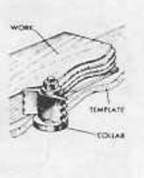
Using a Pattern or Form
Many special shaped edges can be simultaneously shaped and moulded, by the use of patterns and forms. A pattern is a template which is fastened to the workpiece
-15-

— the idea being that when the pattern edge is pressed against a guide or a collar, the edge of the work will be advanced to the cutter in accordance with the shape of the pattern.
A form is a holding device which may be guided by the miter gage groove in the shaper table, or by a pattern which is a part of the form or which is secured to the form together with the workpiece. The uses of patterns and forms are explained in pages 20 through 25.
how to use guides
TWO GENERAL TYPES OF SHAPING OPERATIONS
There are two general types of shaping operations. These are referred to as "edge shaping" and "face shaping."
The best guide for a maiority of shaper operations is the adjustable fence with which your shaper is equipped. This fence can be positioned on the table to ters. When only a portion of the edge is removed in edge shaping - and for all face shaping operations - the two faces of the fence are kept in parallel alignment. However, when the cutter removes material from the whole width of the workpiece edge, it is necessary to advance the rear face of the fence farther outward than the front face by a distance equal to the depth of the cut (as shown in the accompanying illustrations).
USE OP A HIGH FENCE
When face shaping wide stock the adjustable fence furnished with your shaper is not high enough to provide proper support for the workpiece. For such an operation, it is advisable to


make up an auxiliary high fence as illustrated. This fence can either be secured to the table top with C-clamps, or by providing slots in the base of the fence which will permit it to be bolted to the table in place of the adjustable fence.
USE OF A LONG FENCE
When work too long to be properly supported by the shaper table is being done, both the accuracy and safety of the operation are greatly improved by using an auxiliary long fence. This is constructed much like the high fence — except that the base of the fence is designed to support the work.

USE OF A MITER FENCE
Work can easily be planned to have a mitered or beveled edge, or can be moulded at a bevel angle if you use a simple homemade miter fence. The design for such a fence is illustrated. When the edge of the workpiece is already beveled, the guide is made to be in a vertical position, and the angle between the base and the table should be the same as the angle of the bevel. When the workpiece edge is square,

eration, it is advisable to
- 16 --

the angle between the guide and the base should be 90°, and the angle between the base and the table should be the angle of the desired bevel.
USE OF AN OUTSIDE-CIRCLE FENCE
When work having an inside curved edge is to be shaped, an outside-circle fence is used. As the operation is generally one of edge shaping, this fence can
be simply a flat thick board clamped or bolted to the table top. The fence face against which the workpiece is to be pressed must have exactly the same curvature as the workpiece edge.
USE OF AN INSIDE-CIRCLE FENCE
When an outer circumference is to be shaped, an inside-circle fence is used. As in the case of the outside-circle fence, this can be a flat thick board clamped to the table top. The contour of the curved edge of the fence should have the same radius as the contour of the workpiece edge.

A universal-type inside-circle fence, having a large V-notch, is also illustrated. Such a fence is adaptable to many different sizes of circular workpieces.
USING CIRCLE FENCES FOR FACE SHAPING
A circle fence can be clamped to a high auxiliary fence in a vertical position for the face shaping, as illustrated. In
the case shown the cutter is located high on the spindle, and the spindle is elevated so that the cutter will be above the top-center por-

GUIDES WITH BUILT-ON HOLD-DOWNS
Special fences of various types can be made for handling various types of materials. Generally speaking, these must of necessity be

at least as far as the home craftsman is concerned. More elaborate, permanent, fences require too much work to justify their construction. One good example, however, of such a fence that is very handy in the workshop, is a strip moulding guide. Such a guide is necessary to hold narrow pieces for edge moulding. The illustration shows the guide in use. Details of this device are shown on page 21, in the section entitled "How to use Patterns and Jigs."
USE OF STOPS
Stops are necessary to control the travel of the work past the cutter when making grooves, flutes, and moulded edges which do not extend the full length of the work. The simplest stop is a piece of scrap wood clamped or screwed to the fence at the required starting or stopping position. Stops can be secured to the fence on a pivot which will permit them to be rotated out of the way when not needed.
A useful type of stop for production work is the disappearing stop. This is simply a round or square piece of wood fitted into a hole in the fence, with a rub-

ber band or spring behind it to hold it out in place when needed. The rubber band or spring can be pushed to one side and the stop can be pushed back into the fence out of the way when not needed.
USE OF A FIXED PUSH SHOE
Most of the fences already described can easily be fitted with a fixed push shoe to act as a hold-down directly above the cutter. This is simply a flat bottom block of wood that is clamped or bolted to the fence at a

proper height to just touch the workpiece as it passes the cutter.
-17-
how to use collars
GENERAL

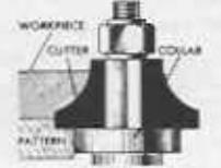
Collars mounted on the spindle above and/or below a cutter, or between two cutters, afford a bearing surface against which an uncut edge of the workpiece can be pressed to regulate the depth of cut taken by the cutter. Because the collar is rotated by the spindle, it will slightly burn and darken the edge of the workpiece pressed against it - but this can be easily sanded off after the operation. The collar must be kept clean by washing it regularly with a stiff brush and benzine or gasoline to remove wood gum deposited on it. Also, the edge of the work to be pressed against the collar must be smooth and regular in contour as all irregularities will be duplicated by the cutter. Provide a good bearing on the edge that is to be pressed against the collar-do not leave such a thin edge- that it will not serve properly as a guide. Typical arrangements of collars are shown in the above illustrations.
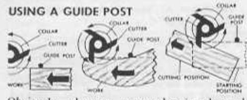
Obviously, when an uncut edge is advanced toward a cutter-collar set-up, it will first strike the cutter — it cannot bear against the collar until the cutter has "bitten into" the edge. For this reason, a considerable amount of kick-back is obtained at the start of a cut. One method of overcoming this kick-back is to use the guide post with which most shapers are equipped. This steel post can be fitted into any one of the four bores in the table

top adjacent to the spindle. By pressing the work firmly against the guide post, it can safely be fed to the cutter to start a new cut without kick-back. As soon as the cut is started, swing the work away from the guide post and press it in against the collar.
USING A STARTING BLOCK
A starting block can be used instead of the guide post. This can be any scrap block of wood clamped to the table to take the place of the
Typical use of a starting ( block is illustrated.
Another type of starting block, called the "sliding starting block," is also sometimes useful. This is any piece of scrap wood having the desired moulding shape already cut on one edge and fitted to the workpiece so that the cutter will rotate in the previously made cut and will slowly bite into the workpiece as the workpiece is advanced to it.
USING A CROWN BLOCK
A workpiece that is curved in two directions — like the head rails of some chairs — can be edge moulded against a collar by the use of a crown block. Obviously, if the workpiece is fed to the cutter straight across a flat table, the center of the bow would be too high up for the cutter to reach it. The crown block is simply a piece of scrap wood fastened to the table adjacent to the cutter so that the bowed workpiece can be moved in an arc across it to be in constant contact with the collar and cutter.


how to use patterns and forms
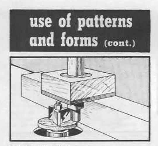
GENERAL
A pattern is any piece of preformed wood, metal, plastic, or other material to which the workpiece can be attached so that the pattern will guide the workpiece by following a guide or a collar. A form is any type of jig designed to hold the workpiece in a special position while it is being guided by a pattern, a guide, the miter gage groove in the table, a collar, or a combination of any of these.
PLANNING PATTERNS
Patterns are generally made from scrap wood of sufficient thickness — 1/2 to 7.8 inch — to give substantial support to the workpiece and provide a bearing edge for pressing against a guide or collar. When shaping the complete perimeter of a small workpiece, it is best to make the pattern in one piece, or to prepare a builtup pieced pattern, as shown. However, if only portions (such as the ends of a table) are being shaped to a pattern, the pattern can be separate pieces of shaped wood attached to the necessary portions of the workpiece. It is only required that the edge of the pattern have the exact contour desired for the finished workpiece — that it be smooth and continuous from end to end of the whole portion to be shaped.
The pattern can be attached to the workpiece in several ways; but it must be anchored so that it will not slip when in use. It can be nailed or screwed in place, can be held by anchor points (as illustrated)— or can be glued with paper between so that it can easily be removed afterwards. When identical
two more sides of a workpiece, a single pattern for one side can be prepared — and can be moved from side to side to complete the job.
The quickest way to make a pattern is to lay out the desired edge shape in pencil on the stock to be used for the pattern—then to cut out the pattern on a band or jig saw.

PATTERNS IN USE
In use, the edge of the pattern rides against a collar, against the fence, or against a suitable guide clamped to the table. The pattern can be designed to ride against the collar above or below the cutter — or can be designed to be partially cut away by the cutter during the progress of the work, so long as sufficient bearing remains for pressing against the collar.

DOUBLE PATTERNS
When a moulding is to be cut on a workpiece that is identical on two or more sides, it is sometimes an advantage to make two identical patterns and to sandwich the workpiece between them, as illustrated. This arrangement allows the work to be turned over at any time to favor the grain, or to make the cutting easier.
Another advantage of this arrangement is that the work can often be held between the double patterns without nailing, screwing, or clamping — and will not slide out of place if sufficient down pressure is maintained during the operation.

- 19-
use of patterns and forms (cont.)
PLANING A REVEL
By using a pattern together with a straight cutter and either the fence, or a collar on the spindle, a workpiece edge can be planed on the shaper to any desired contour which the cutter can be made to follow.
If the indepartions in the edge are too deep at any point for the cutter to cut them out the cutter two or more times as necessary
hold the workpiece at the a bevel edge (either plain shaped in the same manner at one angle, and changes be designed to twist the

DOUBLING UP PATTERNS
When long, harrow shapes are to be contour planed or edge moulded and a number of identical pieces are to be made, a doubling-Use of such a pattern keeps the hands well away from cutter. The two edges of the pattern are shaped like the two edges of each

marknings are to be shaped - but the pattern workpiece are to be shaped - but the pattern is twice or more the width of the workpiece. two workpieces are then reversed in their posi-
The pattern illustrated uses bolts with wine in place. Workpieces can also be held in the
TWO USEEU SUDING HOS
Two typical homemade jigs, designed to slide is especially useful for face shaping. The other positions for edge shaping.
Typical uses for these jigs are illustrated. Although the jigs shown are designed to slide in the miter gage vantageous to remove the ruide bar from the under side of such a jig, and to use the jig to hold both a for guiding against a col-


STRIP SHAPING JIG
The above illustration shows a jig which will greatly facilitate strip shaping operations. This type of jig is particularly useful when shaping work which is small, and consequently, rather flexible. Without the use of a jig, it is usually somewhat difficult to work with small stock since the work cannot be held rigid and guided properly during the shaping operation. Clamp the jig to the table of the shaper with C-clamps so that the cutter opening in the jig and the guide channel formed by the spring and jig guide strips is properly oriented in respect to the shaper cutter. Perform shaping operation by feeding the work through the guide channel of the jig.
A PIVOT JIG
A simple pivot jig makes it easy to shape and edge mould round or circular workpieces. Construction of the jig is illustrated above. The base is designed so that it can be clamped to the shaper table at any desired position — and the turntable is pivot mounted to the base so that it can be rotated in a true circle while supporting a workpiece placed on top of it.
If the work is a full circle (so that the work must be advanced into the cutter before it can be rotated), start the cut by shoving the jig and workpiece toward the cutter and up against a stop block which will limit the depth of cut as desired. After the cut is started, stop the machine and clamp the jig to the tables, before rotating the turntable to form the circular edge.
A ROUNDING JIG
This jig also consists of a turntable pivot mounted to a base which can be clamped to
the shaper table. In this case, however, the turntable is designed to hold square workpieces and has side guides against which the workpiece can be firmly positioned.

A TYPICAL HOLDING JIG
When an irregular shaped workpiece — such as an octagonal-shaped table leg or a cabriole chair leg — is to be finished with edge or face moulding designs, a specially made holding jig is required. The jig is built up from scrap wood so that it will properly support and securely hold the workpiece. If the work-

piece is to be worked against a collar, the bottom part of the jig can have a pattern cut on one or both sides — and the entire jig serves not only to hold the workpiece, but also as a pattern guide. The jig can also be designed to slide against the shaper fence or in the miter gage groove of the table top. A typical holding jig is illustrated above.
A ROCKING JIG
The use of a crown block (page 18) for edge shaping of work that is curved in two directions has already been explained. Another method of handling these compound-curved workpieces is to use a rocking jig. A typical jig design is illustrated above. The jig is shaped to hold the curved workpiece — and the bottom piece of the jig is a pattern.
In use, the pattern edge of the jig is pressed against a collar, and the jig is rocked as the work is fed to the cutter, to keep the workpiece edge at a constant height above the table at the point of contact with the cutter.

A TENONING JIG
Round tenons at the ends of square workpieces can often be cut on the shaper quicker and more easily than on a lathe. A simple homemade jig and a wooden collar mounted on the spindle are all that is required.
The jig is set up as illustrated, with the wooden collar on the spindle underneath the cutter to limit the length of the tenon. The jig consists of a block of wood which holds a circular plug having square center opening, so that the workpiece can be inserted through the plug and revolved on a vertical axis. A thin piece of wood on the bottom of the block holds the plug in place. The work is fed slowly downward against the cutter antil the proper depth of cut is reached — and is then slowly revolved against the direction of cutter rotation to complete the contour of the tenon.
A BEVEL JIG
Bevel edging at any desired angle is quickly and easily accomplished with an adjustable bevel jig like the one illustrated at bottom of page. This jig consists of a table hinge mounted to a wood block that can be bolted or clamped to the shaper table. A slight shoulder on the table provides a straight-edge guide against which the workpiece can be slid for feeding to the cutter. The angle of the table with respect to the shaper table is determined by the guides (one at each end of the table) which can be clamped against the edge of the shaper table.
With the jig in place, a workpiece can be quickly planed or moulded at any prescribed bevel angle. Workpiece with equal size faces (such as a hexagonal column) can be easily created out of round or square stock by using this bevel jig. It is only necessary to determine the angle between any two faces of the desired figure — then to set the jig to this angle and plane each face in turn to the finished size of the face. In order to determine the angle and width of the face, make a full scale crosssectional drawing of the finished column, then measure the faces with a ruler and the angles with a protractor.
A FLUTING JIG
This homemade jig has many useful purposes. The head stock holds a revolvable index head into which is fitted the head-stock shaft. This index head is drilled at the end with a series of equally spaced small holes to divide a circle into 24 parts. Selected holes will therefore divide a circle into 2, 3, 4, 6, 8, or 12 parts. A nail inserted through a hole in the head stock will engage one of these holes to hold the index head stationary at a desired


position. The tail stock is adjustable for different length workpieces.
The overall height of the jig centers must not exceed the height above the shaper table at which a cutter can be located on the spindle. The jig is used only as a holding device and one edge of the base must be parallel with the centers so that the whole jig (with the workpiece on the centers) can be guided by a collar on the spindle or by a guide clamped to the shaper table.
Use of the jig makes it easy to produce a column with an equal number of equal-size faces — with flutings — or with specially moulded designs.
A RADIAL ROSETTE JIG
By using an index head very much like that used with the fluring jig above, together with a wood-block slide which will hold this head on an axis at a right angle to the cutter, you can build a simple jig which will quickly produce radial rosettes at the end of a workpiece. The index head can be rotated in the slide and can be secured by a nail at various desired stop positions. The workpiece is clamped to the face of the index head — and the whole jig is positioned on the shaper table so that the slide will carry the workpiece past the revolving cutter. The axis of the index head and the horizontal center of the cutter must be the same height above the shaper table.
In use, the work is passed in front of the cutter at different positions of the index head to produce a pattern on the end of the work. An inside-circle guide (page 17), positioned

vertically can be used instead of the horizontal guide illustrated to hold the slide,— then the work will be passed in front of the cutter on an arc, and the radial lines of the resulting rosette will have a spiral effect. If this type of guide is used, the lowest point of the guide must be in line with the vertical center line of the spindle.

E
0
0
SASH AND DOOR SHAPING
With the use of proper shaper cutters and collars, sash and door shaping operations can readily be performed with your shaper. A sash and door cutter kit consisting of a cutter, collars, etc., is available. Although standard sash and door stock is 1-3/8-inch material, and the collars of the sash and door cutter kit are designed specifically for working with standard 1-3/8-inch sash and door stock, stock of other thicknesses can be worked by varying the combination of collars.
Figure (A) shows the shaping of one side of a door stile.
Figure (B) shows the setup for shaping the second side of a door stile. In addition to the main shaper cutter, a 1/4-inch straight face cutter is used in combination with the standard cutter.
Figure (C) indicates the sash coping operation of a door rail end. The second coping operation on the door rail end is accomplished by simply turning the stock over. Figure (D) indicates set-up for shaping a window sash stile. This combination consists of the standard sash and door course traverther and the
spacer collar of required thickness and a straight face cutter which cuts the glass rabbet. Figure (E) indicates the set-up for coping the window sash rail ends.
JOINTING
Edge jointing is easily accomplished with a straight cutter and proper adjustment of the of the fence so that the workpiece, when pressed against it, will just touch the cutter. Now position the front face so that it is in back of the rear face by a distance equal to move from the workpiece edge.
Very deep cuts should not be taken on the occasionally be made, if desired. Best practice is to take small cuts and make as many passes
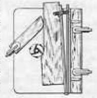
TAPER JOINTING
ing - except that the workrear face of the fence. This

front faces), and - if the edge of the workpiece is held firmly against the front face as the work is advanced — will result in a taper. cutter, the edge can be moulded and tapered
Rip planing differs from regular planing and other shaper operations in that the workpiece is not only planed (or moulded) at the edge, but is also reduced to an exact size at the same time. This is easily accomplished on - and by running the work between this guide
Because the workpiece is forced between the
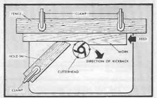
iliary fence. Any scrap board clamped to the table top can be used as a hold-in; or the regular shaper fence can be used. If the regular fence is used, back the front face away tacts the work to serve as a hold-in.
To position a hold-in, move the auxiliary fence over so that it just touches the cutter, then place the hold-in in contact with the auxiliary fence. Now move the auxiliary fence away from the cutter a distance exactly equal to the desired width of the finished workpiece.
Any type of moulded edge can be produced while rip planing. This is
produce a tapered workpiece to exact dimensions. taper is desired, simply place a tapering jig (see book No. 2926, The Circular Saw) between the auxiliary fence and jig to the desired angle.
PANEL RAISING
Panel raising is a very useful operation in the building of cabinet doors and the like - a raised panel being simply a workpiece which = is reduced in thickness on all edges to fit the groove of a frame built to surround it.
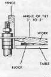
One method of panel raising is to use a small circular saw with a beveled edge in place of a cutter on the shaper spindle. As the saw blade will be perfectly horizontal, it is necessary to block the workpiece up at an angle under the saw blade to produce a taper at the reduced workpiece edge. A set-up is illustrated above.
A novel raised panel having a groove at the edge of the raised portion can be made by using a chipper from a dado head set. As

the chipper is a straight blade, the work must be blocked up, the same as when using a saw blade. The chipper must be sharpened atong both leading edges
SHAPING FIGURES
make quantities of duplicate alphabet letters or other small design pieces for use in decorations or for games. An easy way to do this is to cut the design into a long strip of wood using your shaper cutter. Afterwards, you can cut the strip up into many parts with a saw - and the resulting flat finures will all be identi-
MAKING DOWELS
Perfect dowels can be cut on your shaper by using either of two methods, Both methods require considerable care in making an exact setup so that cuts taken by the cutter will match perfectly to produce a perfect circle.
This, however, is merely a matter of taking the time to set the cutter at the right height, and the fence at the right depth of cut.

The first method is to take four corner cute on a piece of square stock — the four cuts each being exactly 1/4 of a circle and meet. ing exactly to complete the circle. The second method is to take only two cuts each being a semicircle. If the dowel being produced is large enough the workpiece can be fed freehand — but a guide, such as used for strip mouldings (page 21) should be set-up when
OPNIAMENITAL DESIGNS
By using different patterns, cutter shapes, and arrangemore you will be able to produce many hundreds of different ornamental designs with your shaper. It would be impossible in this small book to illustrate and describe in detail all such possible designs - but two typical ornamentations are illus-
by using a waved edge pattern which will vary the depth of cut as the work is pushed past the cutter and - in this case - by using
The first is easily produced

a cutter smaller than the thickness of the workpiece. The second design is produced by making a series of "staged" cuts, instead of a continuous long cut on the workpiece. The "staging" of the cuts is obtained by using a notched pattern and a stationary pin clamped to the table. The notches are engaged over the pin, one after another, to hold the workpiece at fixed positions with respect to the cutter. In the case illustrated, the cutter selected has produced cylindrical, straight sided cuts in the edge of the workpiece - and the pattern notches and pin have been used to space these notches at equal intervals along the workpiece edge. Each cut is made by pushing the workpiece into the cutter up against a collar which limits the depth of cut - and by then backing it off of the cutter and moving it along to the next pattern notch to repeat the process. Unequal spacing of the cuts can be used if desired - and two or three rows of cuts at different heights in the workpiece edge can also
- 25---


A moulding cutter head can be used on your shaper, instead of one of the standard shaper cutters — and has the advantage of being a holding device for homemade cutter blades of and ready for use.
SETTING UP THE CUTTER HEAD
Mounting
Using one or the other of the bushings pro vided (for 1/2 in. or 5/8 in. shafts), place the cutter head over the spindle with the flat sides of the cutter blades facing the direction of spindle rotation. Secure it with the spindle nut.
Use Of Your Fence
Your shaper fence (which probably has a maximum opening between the two faces of 3 inches) will not clear the 6 inch sweep of the cutter head. For smooth efficient operation, not over 1
inch of the cutter head should be exposed -and the fence should encircle the head to a depth of approximately 5 inches. You can bolt wooden extensions onto your fence faces to adapt it. Each extension should be 41/2 in. thick, the same depth as the fence face, and shorter than the fence face by 1% in. Mount the two extensions flush with the outer edges of the fence faces (they will be stepped back 15% in. each from the inner face edges). Now when the faces are fully separated (3 in. between original faces), there will be 61/4 inches between the extensions - and these will surround

-26-
the cutter head to a depth of approximately 5
Regulating Speed
The larger cutter head will have an excessive foot per minute speed at the ends of the cutter blades unless you reduce the spindle speed. It is advisable to use a motor pulley that is 1/2 the diameter of your regular motor pulley.
INSTALLING DIFFERENT CUTTER BLADES
Different blade sets can be installed without removing the cutter head. Change one blade at a time. Be sure that the cutter-head slots are clean so that the blades fit all the way down in them - and extend out exactly the
MAKING YOUR OWN BLADE SHAPES
Purchase Planer blades (Cat. No. 9-2408) which have straight edges. Re-grind these edges to the desired shape — making all three exactly the same shape, and the same length. Bevel all edges at a 15° angle for clearance. Be careful not to draw the temper from the blades when grinding (either use a wet-stone, or air cool them frequently). Finish the blades by honing them carefully (flat sides against stone) to sharpen them.
SELECTING PATTERNS
Use 4-inch squares of vellum or tracing paper and keep a record of each different blade shape. Two or more papers can then be stacked together and shifted about so that, when you look through them, you can see the result of different blade arrangements


SET-UP AND ADJUSTMENTS
Never underpower a planer — always use the manufacturer's recommended capacity motor. Also, keep all moving parts well lubricated, especially the bearings of the motor, cutter head, and rollers. Always set planer on a substanial level surface, with the table at a convenient height for handling the workpieces.
Ordinarily, the only adjustment to be made is the setting of the thickness pointer and scale. To set, place a board of measured thickness in the planer and raise the table until the cutter blades just touch the board — then adjust pointer to indicate proper board thickness on the scale.
CUTTER HEADS AND CONTROLS
Planers may have 2 to 6 knives mounted in a V-shaped, square or cylindrical cutter head. The speed of the cutter head may vary from 3600 to 5000 rpm — as stated by the manufacturer.
The feed — which may vary from 15 to 80 linear feet per minute — is usually controlled by a lever which engages or disengages the infeed and outfeed rollers, as desired. Hand fed models are, of course, much slower.
Depth of cut is generally regulated by a hand wheel which lowers or raises the table (as in model illustrated) or, in the case of double surfaces, may raise or lower the cutter head as well. The thickness pointer actually indicates the distance between the table and the cutter knives. For this reason, depth of cut must be calculated as the difference between the actual thickness of the uncut workpiece and the setting to which you move the pointer on the scale.
HAND FEED PLANER
TYPES AND USES OF PLANERS
A planer is designed to simultaneously surface stock, and to reduce it to an exact desired thickness. In general, planers are classified as "single" or "double" surfacers, depending upon whether they surface one or two sides of a board in one operation. The planer illustrated is a single surfacer, having the cutter head above the table to take a cut from the top side of a board.
Some planers have a continuous traveling table (like a conveyor belt) to feed work to the cutter — some very large sizes have reciprocating tables (like large machine shop horizontal planers) — but most popular woodworking shop models have a stationary table with rollers above to feed the work to the cutter (like the model illustrated). The roller type uses an infeed roller with a fluted or corrugated surface to grip the wood, the table rollers and outfeed roller being smooth. Planers vary in size from 12 to 42 inch cupacity — the capacity being the width of stock which can be planed. Small (12 to 20 inch) planers will handle stock from 1.52 to 4 inches thick.
operation of power planer

GENERAL INFORMATION
It is well to remember that your planer cannot reduce and straighten warped stock at one operation. The pressure of the infeed roller will momentarily straighten a warped board as it advances to the cutter; but the board will re-warp on leaving the outfeed roller. It is therefore necessary, when working with warped lumber, to joint one face of the stock, to mark this "working face," and to run the stock through the planer with the working face down on the table.
Never overload your planer by taking too deep a cut. Maximum cuts are limited by the type, width and dampness of the wood. If your machine will ordinarily take a 1/16-inch cut in 8-inch soft pine — it will not necessarily take the same cut in a 20-inch wide soft pine board, or in an equal width of hardwood board. If you do overload your machine, slow down or stop the feed until the machine again picks up speed. Good work cannot be done with cutters revolving less than recommended speed — and overloading may burn out your motor. Always keep the cutter knives sharp. Think problems through before starting work.
GENERAL PROCEDURE
1. With a ruler, measure the thickness of the stock at the thickest point.
2. Set the planer to remove desired amount of stock (or maximum which should be removed in one cut) from the thickest part of the stock. To do this, position table so that pointer indicates the measured thickness of the stock less the fraction which represents the depth of cut to be taken. To obtain a perfectly true surface and unvarying thickness of less than 1/4 inch on the average planer, it is necessary to set the stock up on a backing board. First, joint and surface the backing board to thickness of 3/4 inch or better, then place the stock to be
3. Release the feed mechanism by turning the feed 'lever to zero feed position to decrease starting load on motor.
4. Start motor and let it gain full speed -----------------------------------
5. Place stock on table (with working face, if already jointed, down) and the grain turned so that the knives will cut with the grain.
6. Place hands on top of stock and push it forward until it is engaged by the infeed roller. Do not hold the fingers along the edges or underneath the stock. Remove hands as soon as stock is being automatically fed.
If using hand feed model, push stock through until a sufficient length of stock projects out back of machine, then walk around to other side and finish piece by pulling it through. Never permit hands to get close to rollers.
REDUCING STOCK TO THICKNESS IN ONE CUT
If work can be reduced in one cut, always make setting and test it on a scrap board — before cutting the workpiece.
REDUCING STOCK TO THICKNESS WITH SEVERAL CUTS
Set the machine for desired first cut and run all of workpieces through before resetting to make second cut. Before making last cut, test accuracy of setting with scrap stock, same as when reducing thickness with only one cut.
If a large amount of stock is to be removed, always remove an equal amount from each face with alternate cuts. The center of a board is nearly always more moist than exterior and if all stock is removed from one side, you will then have one dry and one damp surface. Board will warp as it dries.
REDUCING SQUARE STOCK TO SIZE
When reducing such items as posts or table legs to size on planer, first square two adjacent sides on a jointer and mark these as "working face" and "working edge," respectively. Now reduce to size, placing the working face and working edge down on the planer table for surfacing of the respective opposite sides.
PLANING THIN STOCK
- 29-
To obtain a perfectly true surface and unvarying thickness of less than 1/4 inch on the average planer, it is necessary to set the stock up on a backing board. First, joint and surface the backing board to thickness of 3/4 inch or better, then place the stock to be surfaced on top of this board. The backing board should be slightly wider and longer than the workpiece. Now set the machine to remove the desired amount from the top (thin) board — then run the two boards together through the planer.
sharpening knives and cutters
JOINTER KNIVES Honing
Jointer knives can be kept in satisfactory cutting condition by honing alone, provided the knives have not been abused.
Cover a fine abrasive stone with paper so that it will not damage the surface of the jointer table, leaving the end of the stone exposed. Rotate the spindle to place one knife in the table throat, with the bevel edge of the knife exactly parallel to the front table of the jointer — and hold the spindle so that the knife will remain in this position. To hold the spindle securely, you can wedge the belt with a block of wood, as shown in the accompanying illustration, or you can use a C-clamp to fasten the belt to the machine frame.

Now stroke the knife from end to end with the exposed portion of the stone, keeping the stone flat on top of the front jointer table. Hold the stone so that it does not twist as you move it back and forth. Stroke each knife of the jointer head in turn giving each knife the same number of strokes so that the same amount of metal will be removed from each. Sharpen just enough to obtain true straight edges along the high sides of the knife bevels. The front table should be carefully adjusted so that the stone presses lightly against the full surface of the bevel of each knife.
A small abrasive stick or piece of abrasive paper wrapped around a steel rule can now be used in the same manner as the stone to remove any slight burr turned over by the honing action.
JOINTING
Jointing is done with the machine under power. It is a necessary preliminary step to grinding — and will often condition the blades for honing without the necessity of grinding. Joint-

ing, however, produces a secondary bevel on each knife, because the revolving knives will not strike the stone at the exact angles of their original bevels. Because of this, knives can only be jointed a limited number of times — then must be removed for complete regrinding to re-establish the original bevels and maintain a proper back clearance.
In jointing, the abrasive stone is placed on the front table, as in honing. Because the revolving knives will have a tendency to kick the stone backward, a stop block should be mounted on the table to hold the stone. Raise the front table until the stone is entirely clear of knives. Start the jointer. Now gradually lower the table until the
stone takes a slight bite on the revolving jointer head. Move the stone across the table to joint the full lengths of the knives. Do not make more than one stroke from

end to end. Stop the machine and inspect each knife carefully. No more metal than is absolutely required to put a uniform bevel on each of the knives should be removed. One or two light strokes made in this manner should be all that are required to obtain straight true bevel edges on all of the knives.
Although jointing often produces satisfactory edges, it is advisable to follow the jointing process with a honing process, as explained previously.
GRINDING
Jointer knives are usually made of high-speed steel. They should be ground dry and aircooled at frequent intervals to prevent burning. The abrasive wheel should be of aluminum oxide, medium-soft and about 60-grit. A sanding plate holding an abrasive disc of about 80-grit aluminum oxide can be used, instead. Most jointer knives are ground to a 36" bevel — and this bevel should be maintained in the grinding operation. Great care must be used in any setup in order to make the removal of actual metal as little as possible. Grinding should be preceded by jointing to establish true straight edges at the outer sides of the knife bevels — then, if these edges are not cut into when grinding, but are used as guides (by removing just enough metal to make the bevel of each knife come up to the edge), all the knives will be ground to the same
e ground to the sai ngth.
When using a grinding wheel, the knife should be mounted in a suitable holding block. This block should have a slot cut into one edge

- 30 --
at a right angle to the bottom of the block. The groove thus formed will usually serve to hold a knife securely for the scatwa -----------------------------------
grinding operation—if it does not, wood screws can be used to clamp knife in place. The tool rest of the grinder must be tilted to give the required bevel to the knife. A guide block can be clamped to the tool rest to insure grinding to a straight line. Set the guide block while the grindstone is sta-
tionary, and so that the knife edge is pressed lightly against the stone. Then operate the grinder and slide the holder back and forth
across the guide several times. Stop the grinder, and again reset the guide block, before proceeding. Continue thus until a full bevel, as required, has been obtained. If the tool rest of the grinder
does not tilt, the work can be done by mounting the knife at the required angle in the holder. In case, the exact angle of the cut must be determined by making a full-size layout prior to slotting the
block. Make your layout on paper, using a protractor to establish the correct angle — then slot the block carefully at this established angle.
The bench saw, with a grinding wheel mounted on the spindle, provides a very satisfactory method of grinding knives. The miter gage fur-
nishes an accurate guide; and the raising and lowering mechanism of the saw provides for slight adjustments of the feed to obtain the proper bevel.
When using the bench saw, a fence — instead of the miter gage — can be used as a guide. In this case, the flat side of the wheel (which may be a sanding disc instead of a grinding wheel) is used. The correct bevel can be obtained, either by mounting the knife at an angle in the holder (as already sug-
gested), or by tilting the saw table 36°.
Grinding can also be done in the drill press, using a cup or recessed wheel. In this case, the grinding surface is horizontal — and the holder
stor must be calculated accordingly. A drill press gives the advantage of perfect control over the feed. To properly set the wheel for each cut, bring the wheel down into light contact with the knife edge before starting the operation. Then, apply power to the wheel and make the cut by passing the knife under it along a guide clamped to the drill press table. Reset the wheel for additional cuts in the same manner. Be sure to carefully check the levelness of

the wheel in relation to the knife by sighting at several positions along the knife edge before starting first cut.
SHAPER AND MOULDING HEAD CUTTERS
Made of high-speed steel, these cutters do not often require sharpening. Prior to sharpening, always wash them in benzine or gasoline to remove any accumulation of pitch.
Sharpening is accomplished by whetting the flat side of each cutter on a composition stone or
natural offstone. Always stroke the cutters as if peeling a small slice from the stone. Never work on the bevel edge as this will destroy the original contour of the cutter. Remove burrs formed on the bevel edge during sharpening by taking

very light file strokes along each edge.
If grinding is necessary to remove nicks, it should be done dry on a fine-grit wheel, stopping often to air-cool the cutter and prevent burning. Best method is to hold the flat side of the cutter against the side of the grinding wheel — and to remove as little metal as possible to eliminate the nicks. Always sharpen cutter after grinding.
PLANER KNIVES
General
Planer knives are very much like jointer knives — and are mounted in much the same manner. Grinding of the knives, when necessary, is done in exactly the same way jointer knives are ground. However, honing and jointing cannot be so easily accomplished because of the difficulty in getting at planer knives while in the tool

Set-Up for Honing and Jointing
A convenient homemade set-up for honing and jointing is illustrated above. When mounted in the shaft hangers, the planer head is in the same position with respect to the platform that a jointer head is in with respect to the jointer front table. In this case, however, it is the adjustable shaft hangers that are used to position the head up or down so that an abrasive stone placed at the edge of the platform will properly contact the knives. Be sure to have both hangers at the same height so that the knives will be parallel to the platform. Hangers can be purchased at any Sears Retail or Mail Order Store. Power for jointing can be applied by placing a belt pulley at one end of the cutter-head shaft.
Proceed to hone or joint the knives exactly as instructed under honing and jointing jointer knives.
-31-
| 1/64 = .019625 1/4 = .250 1/2 = .500 | 3/4 = .750 |
|---|---|
| 1/32 03125 17/64 .265625 .33/64 .515625 3/64 .045875 9/32 .28125 17/32 .53125 19/64 .296875 .35/64 .545875 |
49/64 = .765625
25/32 = .78125 51/64 = .796875 |
| 1/16 |
13/16 = .8125
53/64 = .826125 27/32 = .84375 55/64 = .859375 |
| 1/8 = .125 3/8 = .375 5/8 = .625 9/64 = .140625 25/64 = .390625 41/64 = .640625 6/32 = .15625 13/32 = .40625 21/32 = .6525 11/64 = .171875 27/64 = .421875 43/64 = .671875 |
7/8 = .875
57/64 = .890625 29/32 = .90625 59/64 = .921875 |
|
Width
in Inches |
* BOARD MEASURE | ||||||||||||||
|---|---|---|---|---|---|---|---|---|---|---|---|---|---|---|---|
| 4: | 5 | 6 | 7 | 9 | 10 | 11 | 12 | 13 | 34. | 15 | 16 | 17 | 1.0 | ||
| 2 | 0.8 | 0-10 | 1-0 | 1.2 | 1-4 | 1-6 | 1-8 | 1-10 | 2.0 | 2-2 | 2.4 | 2.6 | 2-8 | 2.10 | 3.0 |
| 3 | 1.0 | 1.3 | 1.6 | 1.9 | 2-0 | 2-3 | 2.6 | 2.9 | 3-0 | 3.3 | 3.6 | 3.9 | 4-0 | 4.3 | 4.6 |
| 4 | 1.4 | 1-8 | 2.0 | 2.4 | 2-8 | 3-0 | 2.4 | 3-8 | 4-0 | 4.4 | 4-8 | 3.0 | 5.4 | 5.8 | 6.0 |
| 5 | 1-8 | 2.1 | 2.6 | 2.12 | 3-4 | 3.9 | 4-2 | 4.7 | 5.0 | 5.5 | 5-10 | 6.3 | .6-8 | 7-1 | 7.1 |
| 6 | 2.0 | 2-6 | 3-0 | 2.6 | 4-0 | 4.6 | 5-0 | 5-6 | 4.0 | 6-6 | .7.0 | 7.6 | 8.0 | 8-6 | 9.0 |
| 7 | 2.4 | 2-11 | 3-6 | 4.1 | 4-8 | 5.3 | 5-10 | 6.5 | 7.0 | 7-7 | 8-2 | 8.9 | 9.4 | 9.11 | 10.4 |
| 2.4 | 3.4 | 4-0 | 4-1 | 5.4 | 6-0 | 6-8 | 7-4 | 8-0 | 8-8 | 9.4 | 10.0 | 10.8 | 11.4 | 12.0 | |
| 9 | 3.0 | 3-9 | 4.6 | 5-3 | 6-0 | 6-9 | 7.6 | 8-3 | 9.0 | 9.9 | 10.0 | 11-3 | 12.0 | 12.9 | 13-4 |
| 10 | 3.4 | 4-2 | 5-0 | 5-10 | 6-8 | 7.6 | 8-4 | 9.2 | 10-0 | 10.10 | 3.1-8 | 12.6 | 13-4 | 14-2 | 15.0 |
| 11 | 3.8 | 4-7 | 5-6 | 6-5 | 7.4 | 8-3 | 9.2 | 10-1 | 11-0 | 11-11 | 12.10 | 13.9 | 1.4-8 | 15.7 | 16-6 |
| 12 | 4.0 | 5.0 | 6.0 | 7-0 | 8-0 | 9.0 | 10-0 | 11.0 | 12-0 | 13-0 | 14-0 | 15-0 | 16-0 | 17-0 | 18-6 |
| 13 | 4.4 | 5.5 | 6-6 | 7.7 | 8-8 | 9.9 | 10-10 | 11-11 | 13-0 | 14.1 | 15.2 | 16-3 | 17.4 | 18-5 | 19.6 |
| 14 | 4-8 | 5.10 | 7.0 | 8-2 | 9.4 | 10-6 | 11-8 | 12-10 | 14-0 | 15.2 | 16-4 | 17-6 | 18.8 | 19-10 | 21.0 |
| 15 | 5.0 | .6-3 | 7-0 | 8.9 | 10-0 | 11-3 | 32-6 | 13.9 | 15.0 | 14-3 | 17-6 | 18.9 | 20-0 | 21-3 | 22.0 |
| 16 | 5-4 | 0-8 | 0-5 | 9.4 | 10-8 | 12-0 | 13.4 | 14-8 | 16.0 | 17.4 | 18-8 | 20.0 | 21-4 | 22 8 | 24.0 |
| 17 | 5-1 | 7-1 | 8-6 | 9.11 | 11:4 | 12-9 | 14-2 | 15.7 | 17.0 | 18-5 | 19:10 | 21-3 | 22-8 | 24-1 | 25-0 |
| 18 | 6-0 | 7.6 | 9-0 | 10-6 | 12.0 | 13-6 | 15-0 | 16.6 | 18.0 | 19.0 | 21-0 | 22.0 | 24.0 | 25.6 | 27.0 |
The price of a board is computed on the basis of the number of board feet contained in the board. One board foot is equivalent to the amount of stock contained in a piece of board one foot long, one foot wide, and one inch thick. (For purpose of board feet computation, stock which is less than one inch thick is generally considered to be one inch stock.) To determine the number of board feet in a board by use of the above table proceed as follows. Find the vertical column which corresponds to the length of the board (in feet). Then run down this column to the figure which is horizontally appoint the proper width in inches indicated in the side heading. This figure will be the number of board feet in the particular board. If the board is geater than one inch, multiply, the figure indicated in the table by the actual thickness dimension of the board.
For a board which is eight feet long, eight inches wide, and one inch thick, if will be found that the table indicates a figure "5.4". (The second digit, "4" indicates the fractional portion, in twelling, of a board fout ----4/12 foot.) Thus, the board feet contained is the board is 5.4/12 feet or 51/3 feet. If the board were two inches thick, then it would be necessary to multiply 5.4 by 2. The tatal board feet then would be 10.8 or 10.2/3 feet.
-32-


 Loading...