

Sears | Craftsman Craftsman - How To Do More with Your Power Router - 1975 Instruction Guides
HOW TO DO More with your

Power Router
VER 50 OPERATIONS DESCRIBED AND ILLUSTRATED

Index
| PAGE | |
|---|---|
| THE POWER ROUTER | 3 |
| ROUTER BITS | 4 |
| ROUTER ACCESSORIES | 5 |
| GENERAL ROUTING INSTRUCTIONS | 8 |
| CONTOUR WORK & SURFACING | 10 |
| STRAIGHT-LINE ROUTING & EDGING | 12 |
| CIRCLES & FRAMES | 14 |
| CARVING & LETTERING | 15 |
| TAPER ROUTING & FLUTING | 16 |
| PATTERN & TEMPLATE ROUTING & EDGING | 18 |
| DOVETAIL JOINTING | 20 |
| BUTT HINGE & LOCK-FACE ROUTING | 21 |
| LAMINATED PLASTICS CUTTING & EDGING | 22 |
| SHARPENING BITS & CUTTERS | 23 |
| 33 WOOD JOINTS - HOW TO ROUT THEM: | |
| Two Homemade Holding Fixtures | 24 |
| Types of Cuts | 24 |
| End, Middle, Tee and Half-Lap Joints | 28 |
| Middle Lap on Edge With Groove | 29 |
| Dovetail Lap | 29 |
| Cogged Joint | 29 |
| Box Joint | 29 |
| Dado Joints | 30 |
| Mortise and Tenon Joints | 31 |
| Tongue and Groove Joint | 32 |
| Mitered Joints | 32 |
| Lock Joint | 33 |
| THE ROUTER CRAFTER | 34 |
NOTE
All operations explained in this book can be performed with any Sears Router equipped with the accessories designed and sold for use with the router.
Read the complete Safe Operating Instructions in the Owner's Manual packaged with your tool.
| DO |
Disconnect the tool from power source
when installing or removing router bits — and tighten the chuck securely after in- stalling a bit. |
|---|---|
| DO NOT | Make any adjustments of your tool or workpiece while the tool is running. |
| DO | Keep your tool, motor and cutters clean. |
| DO NOT |
Use dull, rusted, bent or gummed bits –
or allow sawdust to clog the tool motor air vents. |
| DO | Make certain that your workpiece cannot move during an operation. |
|---|---|
| DO NO | 7 Attempt to hold workpiece with one hand while guiding the tool with your other hand. |
| DO | Keep a firm, two-handed hold on your tool throughout each operation. |
| DO NO | T Let your attention stray, or handle your tool carelessly. |
CRAFTSMAN HANDBOOK
A MIDWEST TECHNICAL PUBLICATION
Copyrighted 1975 SEARS, ROEBUCK and CO.
Printed in U.S.A
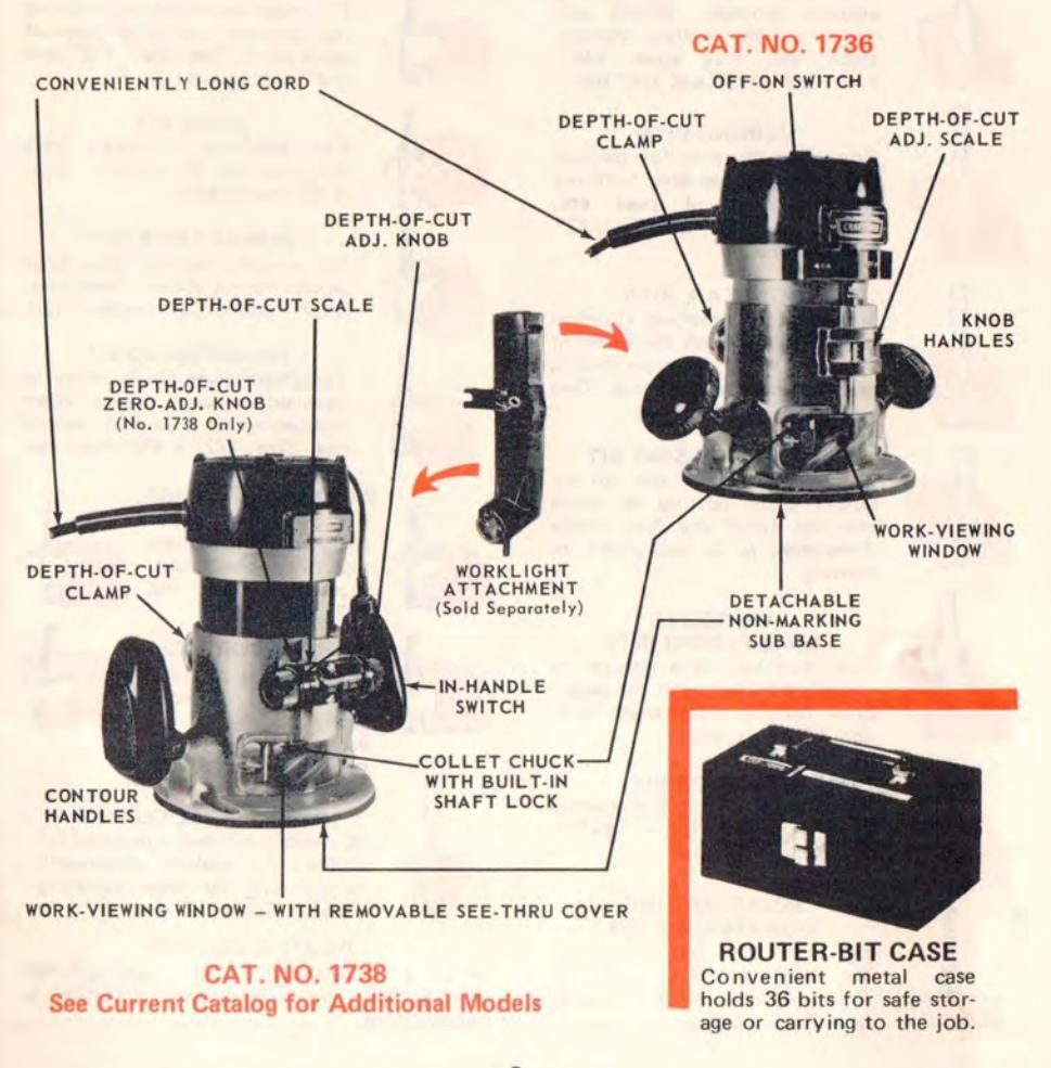
THE Power Router ...
AN ELECTRIC CHISEL AND CARVER COMBINED
Either model, lightweight Craftsman Power Router is a very versatile workshop tool. Properly handled, it will perform like an "electric chisel and hand carving knife" to accomplish with power — many otherwise tedious jobs. With it, you can do grooving (square, round, dovetail or V bottom, straight or curved lines), mortising, inlaying, edge shaping (inside or outside edges), carving (pattern or freehand), dovetail jointing ... and many similar jobs which cannot be done half so easily
by hand, or even with other types of power tools.
The excellent tool adjustments and accessory guides available help you to do precision work. However, as with any powerful, high-speed tool, your router does require accurate set-up and handling — and you will need some practice — in order to turn out the quality work for which your tool is designed. Keep this book for reference and study.
Router Bits ...
chuck of any Craftsman and most
other routers. The winged bits are shaftless — must be mounted on
an arbor (sold separately), as
shown in the following illustra-
tions of the bits. Refer to a
current Sears catalog for types,
sizes and model numbers of avail-
KROMEDGE BITS
Long-lasting chrome-impregnated steel bits resist rust and gum buildup for clean, fast cutting in softwoods and hardwoods. The onepiece bits have integral, 1/4-in. diameter shanks to fit the collet
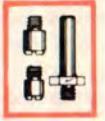
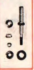
ARBOR WITH PILOTS
Holds winged bits. Two interchangeable pilots - 5/16" and 3/8" dia. - for limiting depthof-cut when edging.
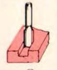
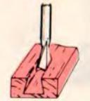
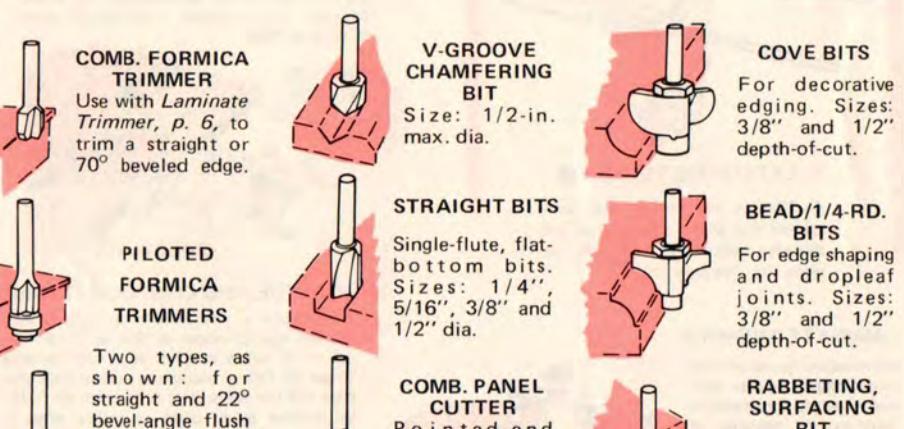
STRAIGHT BITS
Flat on bottom for cutting square grooves, rabbets and dados and for leveling recessed areas, etc. Five sizes: 1/8", 1/4", 3/8", 1/2" and 3/4" dia.

VEINING BITS
Round on bottom for decorative grooving, carving, lettering and making small coves, etc. Four sizes: 1/8", 3/16", 7/32" and 1/4" dia.
DOVETAIL BITS
Required for making dovetail drawer joints (with the Dovetail Fixture , p. 6 ) dovetail dados, and decorative grooving. Two sizes: 1/4" and 1/2" dia.

HINGE-MORTISING BIT
Special design 1/2" dia. bit for quick, clean cutting of hinge mortises (with the Butt Hinge Templates , p. 6 ) and panel indenting.
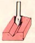
V-GROOVE CHAMFERING BITS
For cutting V-grooves or chamfered edges, and for decorative carving. Two sizes: 1/2" and 7/8" max. dia.
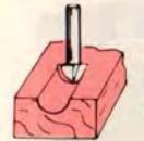
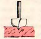
CORE-BOX BIT
turning on the Router Crafter,

POINT-CUTTING QUARTER-RD. BIT
For decorative grooving, carving, beading and – with the Router Crafter , p. 5 – roping. Size: 3/16" radius.
able bits.
POINT-CUTTING OGEE BIT
Also for decorative grooving, carving, beading and for roping with the Router Crafter , p. 5. Size: 9/32" max. radius.

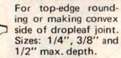
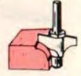
For edge decoration and making the concave side of a dropleaf table joint. Two sizes: 1/2" and 3/8" depth-of-cut.
OGEE BIT
For making rounded edge decorations as shown. Size: 3/16" depth-of-cut.
ROMAN OGEE BITS
For making recessed Ogee edge decoration as shown. Two sizes: 5/32" and 9/32" depth-of-cut.
CHAMFERING BIT
For chamfering thick edges or bevel-edge panel raising when Rabbeting bit is used for second cut. Size: 1/2" x 45° max. cut.
BEAD/QUARTER-RD.
RABBET/SURFACE Used with a pilot for
rabbeting, without for surfacing or use with Router Crafter , p. 5. Size: 15/16" dia.
COMB. PANEL CUTTER
A straight bit that is pointed for drilling. For making latticework or cut-outs, or edge trimming veneers. Size: 1/4" dia.
ADDITIONAL BITS
Also a double-end 1/16" veining/1/16" straight bit and a double-end 45°/60° Vgrooving bit.


... and Accessories
CARBIDE-TIPPED BITS
Like the Kromedge Bits, p. 4 – but will stay sharp and fast-cutting in softwoods at least 15 times longer.
pilots o
With two ball-bearing pilots (1/2" and 5/8") for winged bits below.
BIT For 5/16" or 3/8" wide rabbets and for surfacing.
ALSO ROUTER-BIT SETS IN CONVENIENT STORAGE CASES
straight bit for
through routing.
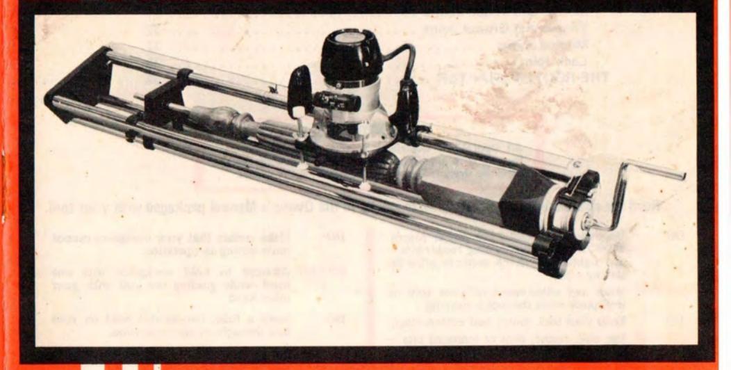
ROUTER CRAFTER
Amazing new accessory that adapts your router for wood spindle shaping and carving. Measures 45 x 8-1/2 x 7-in. high; rests on bench or table top and handles square or round workpieces 1- to 3-in. thick, up to 36-in. long.
edge trimming of
Very easy to use.
DOES:
Fluting Reeding Contour shaping Coving and beading Tapering of rounds or flats Right- or left-hand spaced roping Right, left or crossed spiral grooving Hollow carving to produce see-through areas Full-, half- or quarter-rounded workpieces Every thing and more than a wood lathe can do.
REFER TO PAGE 34

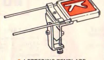
LETTERING TEMPLATE
A 40-piece set (holder and templates) that allows you to rout out shapely letters and numerals for signs, etc. See page 15.
LAMINATE TRIMMER
Micro-adjust guide bearing rolls along straight or contoured edges for precision trimming or beveling of work as thin as 7/16-in. Comes with Formica Trimmer (page 5) for use on toughest laminates. See page 22.
DOVETAIL FIXTURE
นางงางงาง
Sturdy fixture with 1/2-in. dovetail template – holds workpieces up to 12-in. wide and 7/16-in. to 1-in. thick. Quick-change knobs; accurate adjustable depth-of-cut. A 1/4-in. template also available – for stock down to 5/16-in. thick.
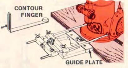
EDGE GUIDE AND CONTOUR FINGER
Easy-to-use — with new micro adjustment. Guides against edges as thin as 3/16-in. up to 6 inches in from edge. Use contour finger to follow along any curved edge (see page 11); use guide plate for any straight edge or remove guide plate to follow edge of circular workpiece (see page 12). Also available without micro adj. or contour finger.

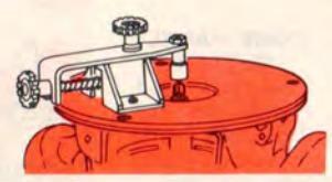
TRAMMEL POINT
Guides router to swing a perfect circle up to 30-in. in diameter. Use for circle grooving, edging or cut-outs. See page 14.

Low-cost, one-piece unit shown guides router for accurate hinge mortising. Larger unit (see page 21) will also space hinge mortises on door and jamb – and serve as a lock-face guide.
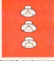
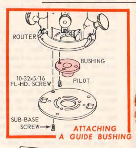
GUIDE BUSHINGS
router along any workpiece or template edge for grooving or shaping of curved contours. Use only the flat head screws furnished for mounting a guide. See page 18.
SHARPENING KIT
Helps you to quickly and accurately sharpen router bits for cleaner, easier routing operations. See page 23.
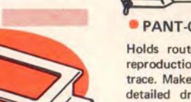
PANT-O-GRAPH ACCESSORY
Holds router and guides it for faithful reproduction of any design you wish to trace. Makes it easy to engrave signatures, detailed drawings, etc. in your work-pieces. See page 15.
Por use with Grantsman and most other routers
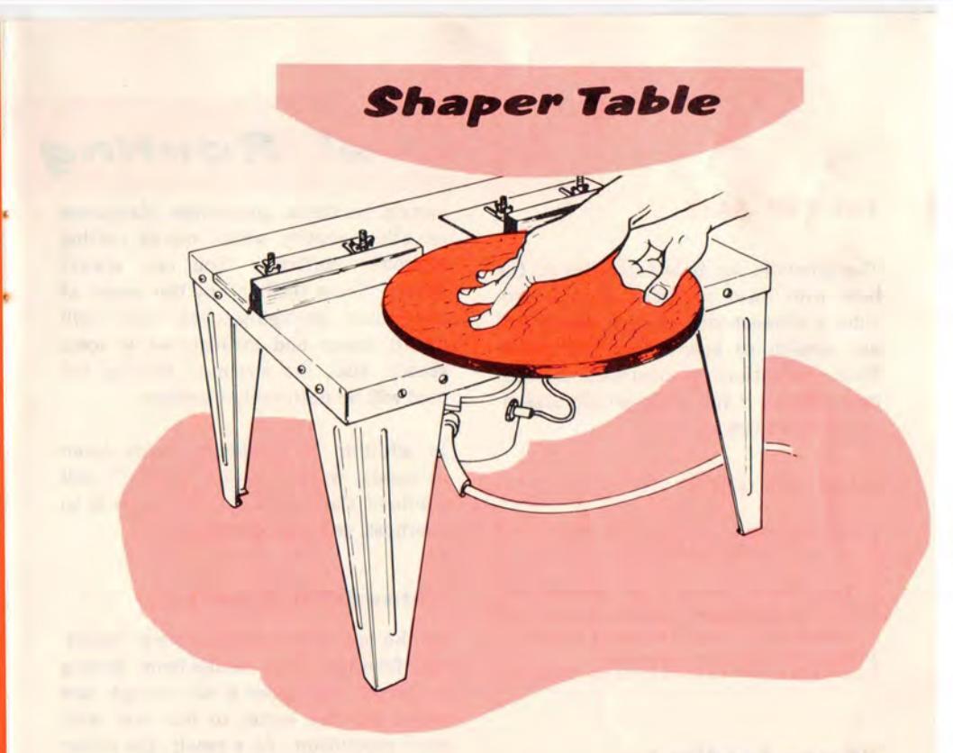
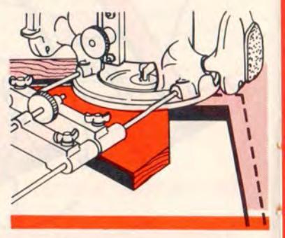
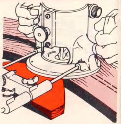
With the table accessory shown your router is converted into a high-speed shaper to which work can easily be fed for accomplishing such projects as: 1) Shaping the entire thickness of a workpiece edge, whether the sides are straight or curved (as in illus.). 2) Routing all the way through a workpiece to create a slot or to produce a latticework design. 3) Carving small, clear plastic pieces by looking down through the plastic to follow a design on the underside. 4) Grooving parallel to a straight or curved edge of any workpiece too small or awkward in shape to be conveniently held for conventional routing. In fact, you can groove, shape, carve, etc. to accomplish practically any operation shown in this booklet without the need of special guides or time-consuming set-ups - on any workpiece that can be held and fed to the cutter.
Your Craftsman (or most any model) router can be mounted quickly to the underside of the table, as shown. In this position it is readily accessible for easy vertical adjustment of the cutter height and use of the on-off switch (which is locked "on" during an operation). The sturdy, all-steel, 14-7/8x16-3/8x11 in. high table can be rested on or bolted to any convenient-height bench, etc. - or, if you prefer a still larger work surface, it can be flush recessed into a larger bench or worktable (in which case the removable table legs are not used). Complete instructions are furnished with the accessory.
Work is guided by being fed in contact with the two, quickly adjustable fences. For further information pertaining to table shaping obtain the Craftsman booklet, " Power Tool Know-How ", Cat. No. 9-2917 or 9-2918.
General Routing
THE SUB-BASE
The phenolic sub-base (attached to the base with three pan-head screws) provides a glass-smooth surface which will not scratch or mar a fine workpiece. When conditions or instructions warrant, remove it for using certain attachments or set-ups.
RATE OF FEED
The whole "secret" of professional routing and shaping lies in selecting the proper feed ... and in making a careful set-up for the cut to be made.
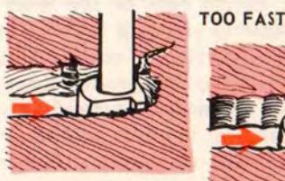
"Force Feeding"
Clean, smooth routing and edge shaping can be done only when the cutting tool is revolving at a relatively high speed and is taking very small bites to produce tiny, cleanly severed chips. If the cutter revolves at a slower rpm in relation to the speed with which it advances through the workpiece, it must necessarily take bigger bites ... to produce bigger chips and a rougher finish. Under extreme slow-down conditions the bites can become so large that the chips will be partially knocked off (rather than fully cut off) . with resulting splintering and gouging of the workpiece.
Your router is an extremely high-speed tool (25,000 rpm no-load speed), but it will slow down in proportion to the load placed on it. "Force feeding" will slow it down. "Force feeding" is trying to advance too rapidly for the size of cut being taken in a workpiece having a
certain hardness, gumminess, dampness or other quality which makes cutting relatively difficult. You can always detect "force feeding" by the sound of the motor. Its high-pitched "whir" will sound lower and stronger as it loses speed. Also, the strain of holding the tool will be noticeably increased.
In addition to producing rough (even chipped) work, "force feeding" will overload the motor ... will cause it to overheat, and may damage it.
"Standstill Feeding"
At the opposite extreme there is "standstill feeding". This results from feeding so slowly that there is not enough new wood for the cutter to bite into with each revolution. As a result, the cutter "bounces" around in the cut already made ... may score and ripple the sides of the cut ... may glaze them ... may even burn them. At the same time the cutter, itself, may be burned so that it loses its temper - and its sharpness.
You can detect "standstill feeding" by listening to the "runaway" too highlypitched sound of the motor; or by feeling the "wiggle" with which the cutter is bouncing around in its cut.
Proper Feeding •
TOO SLOW
IMPROPER FEEDS
Instructions
The right feed is neither "forced" nor "standstill". It is the rate at which the cutter advances firmly and surely (without hesitation or noticeable laboring) through the work. If you are making a small-diameter shallow cut in soft, dry wood, the proper feed may be about as fast as you can travel the tool along your guide line. On the other hand, if the cutter is big, the cut is deep, or the wood is hard, damp, gummy or knotty ... then the proper feed may be very slow.
There is no fixed rule. You will have to learn by experience and by using good judgment. If at all possible, always test the cut to be made on a scrap of the workpiece wood.
DEPTH OF CUT
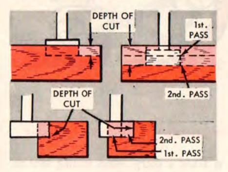
This is important only insofar as it affects the rate of feed. When using a small diameter bit on easy cutting wood, you probably can cut as deeply in one pass as the bit will go — and still be able to maintain the proper rate of feed. But as the bit size and/or the wood toughness are increased, the maximum advisable depth of cut in a single pass will be decreased. With the largest cutters we recommend — in general —
that you do not exceed 1/8 inch depth in one pass. To cut deeper it is much better to make as many successive passes as required, each no deeper in new wood than 1/8 inch.
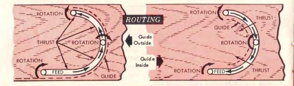
DIRECTION OF FEED AND THRUST
Your motor and cutter revolve in a clockwise direction. This means that a tool will have a slight tendency to twist in a counterclockwise direction, especially when the motor revs up (as at starting).
Because of the extreme high speed of cutter rotation during a "proper feeding" operation, there is very little kickback to contend with. However, should you strike a knot, hard grain, etc. that would affect the normal progress of the cutting action, there will be a slight kickback ... sufficient to spoil the trueness of your cut if you are not prepared. Such kickback is always in the direction opposite to the direction of cutter rotation.
To guard against kickback, plan your set-up and direction of feed so that you will always be thrusting the tool — to hold it against whatever you are using to guide the cut — in the same direction that the leading edge of the cutter is moving.
If you are routing, tool travel should be from left to right and counterclockwise around curves — if the guide is positioned so that your thrust is as shown in the first accompanying illustration. But reverse this if the guide is positioned as in the second illustration. It is generally easiest to use the first set-up. (See following page for the two illustrations.)
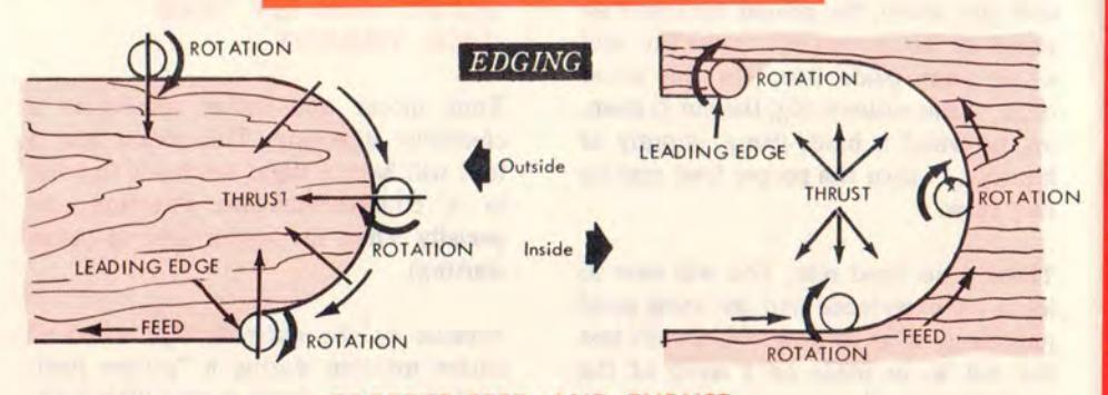
CORRECT FEED AND THRUST
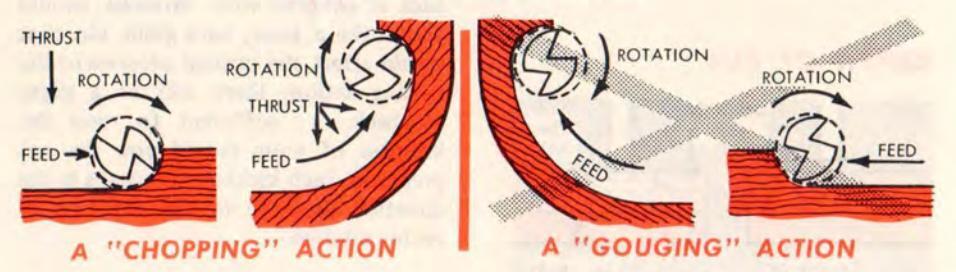
If you are edge shaping, the feed should always be clockwise when working on an outside edge; but should be counterclockwise when doing an inside edge (accompanying illustrations). The reason for this is that when traveling the tool as instructed, the cutter will have a "chopping action"; but if you reverse direction, it will have a "gouging action". "Chopping" is much preferable to "gouging" as there is less danger of ripping out chips by tearing the grain.
PROPER CARE OF CUTTERS
It takes a sharp, clean cutting tool to accomplish professional quality work. A dull cutter makes a sloppy or rough cut, requires more feeding force, and can overload the motor. Keep your cutters sharp (refer to page 23) . Remove accumulated gum with Sears Gum and Pitch Remover.
Avoid using enough force to burn the wood; smoking wood means the cutter is overheating — may loose its temper.
DGE SHAPING WITH PILOT-GUIDED BITS
SURFACING
FARTIAL EDGE SHAFING
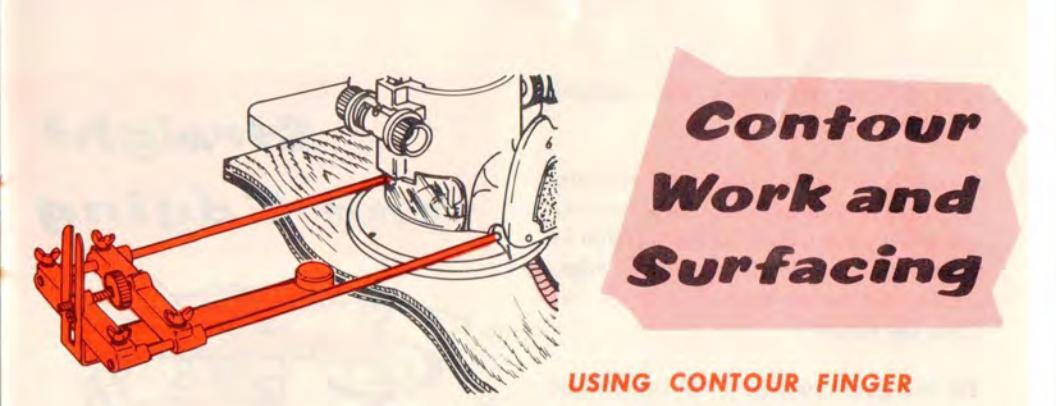
USING CONTOUR FINGER With the Contour Finger attached to the Edge Guide, top illus., the router can be made to follow curved edges against which the contour finger can be pressed. The guide can be adjusted to place the bit at any desired distance in from the edge. Practically any type of convex or concave curved edge that you will wish to "parallel" can be followed.
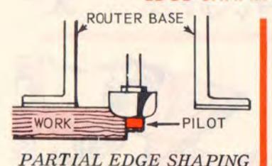
• USING ARBOR-TYPE BITS An Arbor Type Bit with Pilot attached will follow any edge – curved or straight – that the pilot can be held in against. If the workpiece is thick so that only the top portion of the edge is to be cut, the
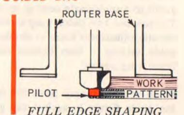
pilot will ride against the uncut lower portion. When all of the edge is to be cut, however, a pattern or other guide that duplicates the edge contour must be clamped to the underside of the workpiece for the pilot to bear against.
• USING THE RABBETING AND SURFAC-
ING BIT With its own pilot or either of the arbor-set pilots attached (page 4) this bit can be used for rabbeting or, with a template, for trueing and smoothing an edge. Without a pilot, it can be traveled over a workpiece surface to plane and smooth a 15/16-in. wide area.
It is difficult to make a truly straight cut freehand.
Straight-line cuts (grooves, rabbets, chamfers and cut-offs) can be accurately made with the use of the Edge Guide to follow along a straight workpiece edge. Guide can be set from 0 to 6 in. out from the cutter.
Fit the guide rods into the router-base bosses and tighten holding screws. Loosen all four wing screws and adjust guide to approximate setting, as shown. Tighten the two outer wing screws and use the adjustment knob to obtain exact guide setting — then tighten the two inner wing screws.
When set up, simply press the face of the guide firmly in against the guiding edge (or straightedge) as you feed the router.
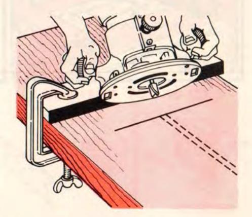
A STRAIGHT GUIDE PIECE
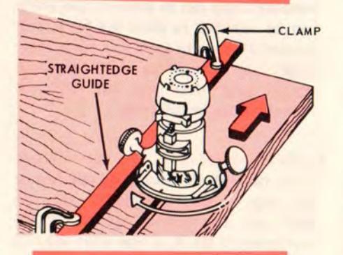
The edge of your router base will slide freely along any suitable guide piece positioned so that you can press the base firmly against it. If you want a perfectly straight cut the guide must, of course, have an accurate, straight edge. It must also be hard enough to resist indentation — and must be clamped securely in position.
Clamp both the straightedge and the work to your bench, offsetting the straightedge enough to place the cut at desired location — and locating it so router will guide along its right edge. This will prevent kickback, if router is fed from left-to-right in the normal manner.
A CIRCULAR GUIDE PIECE
With the guide plate removed the exposed V portion of the edge guide may be used to follow along the edge of a circular workpiece.

Straight

A BOX GUIDE
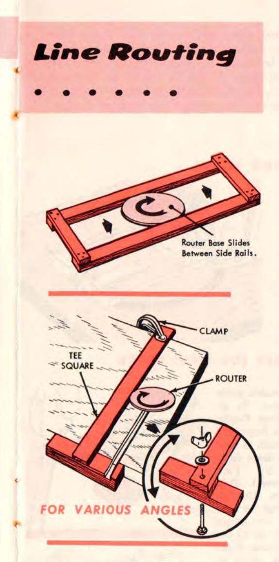
This is simply two straightedges fastened with crosspieces so that the router base will slide between them freely but without slop. Used as a guide for routing on flat surfaces it speeds the work as the router can be held down and pushed with one hand (on top of motor) while the other hand holds the guide. Clamping is thus made unnecessary, if you can hold the guide and work firmly. Sandpaper, glued to the underside of the guide, will make this easier.
A TEE SQUARE
This simple device is useful for making cuts (especially a series of parallel cuts) at a 90° angle to one workpiece edge. Make it as shown, preferably of aluminum or hardwood. Or you can attach the two pieces together with a countersunk bolt and wing nut, so that angles other than 90° can be obtained.
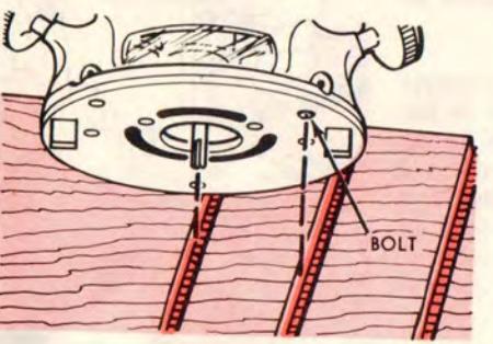
PARALLEL CUTS WITHOUT A GUIDE
If you have routed the first groove and wish to make a series of equally spaced identical grooves (straight or contoured), substitute a socket-head bolt for one of the three sub-base screws ... to serve as a guide. Hold the router steady so that this bolt head will slide in the previous groove — and so that the bit will always be exactly opposite to it (neither ahead nor behind).

Round, square and rounded-corner square table tops, trays, picture frames and similar objects can be cut out and shaped — on both inner and outer edges — with the use of the Trammel Point, Edge Guide, and a few simple fixtures. If arbor-type bits are used the pilots are omitted.
FULL ROUND WORK
If you have the Trammel Point, it can be used as shown to afford a quick, easy method of circle cutting. If desired, the combination panel cutter can be used to cut through the stock to shape a round disc, or a hollow round disc for framing a mirror or picture, etc. Afterwards, the outer edge (or both edges) can be rabbeted, chamfered or shaped in the same manner, using the proper bit.
SQUARE & ROUNDED-CORNER (OR END) WORK
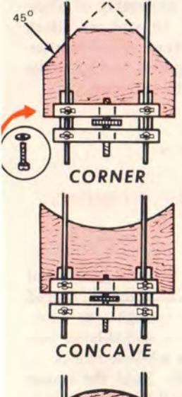
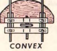
Three types of wooden guide blocks are illustrated. To attach one to the Edge Guide; remove the contour finger and the guide plate (which is held to the inner cross beam from underneath by two 8-32x7/16-in. screws). Drill two 1/8-in. holes through block near rear edge so that these two screws (or longer ones if block is too thick) can be used — with washers under heads — to secure block to cross beam.
The curvature of the concave or convex block should be the same as the curvature to be followed — which can be a preshaped workpiece edge or a pattern. If a pattern is used, an unshaped edge can be cut through for shaping to the curvature.
Carving = Lettering

USING THE PANT-O-GRAPH Instructions
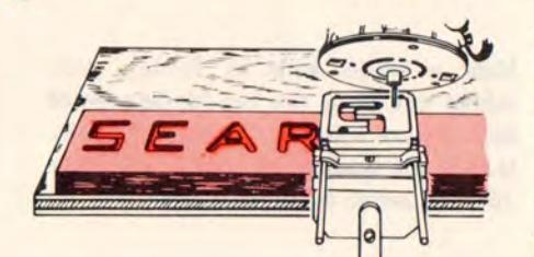
for setting-up are packaged with this accessory. Use any straight, veining or V-groove bit suitable to the design to be carved. Before starting, be sure your design (any flat print, drawing, etc. that is twice the desired finished size) is positioned so you can trace all of it without changing its position. Start the router and lower the bit to the desired depth-of-cut . then simply trace your design with the pant-o-graph tracing point. For additional ingenious effects, vary bits and/or depth-of-cut. or use contrast coloring or filling of the finished engraving. By substituting a pencil for the pant-o-graph point, and by using the router bit to trace a design fastened beneath it, you can create a double-size print, for use in carving an exact-size replica of the original.
• USING THE LETTERING TEMPLATE The clamp supplied simultaneously holds the workpiece and the particular letter (or numeral) guide in use. Router must be fitted with a 5/8-in. or smaller guide bushing ( page 6 ) and a suitable straight, veining or V-groove bit. Simply set bit to desired depth-of-cut and feed it through the guide to engrave any one of the 40 letters or numerals. Using 1/8-in. hardboard, guides may be created for additional figures.
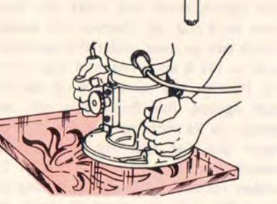
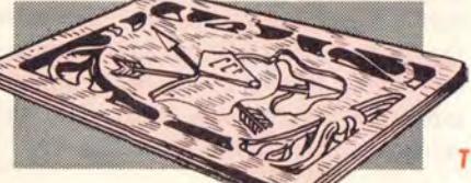
FREEHAND CARVING For engraving or embossing use any bit suitable for the work to be done. To make panel cut-outs, latticework, etc. clear through the work, use the combination panel cutter (which drills its own through hole). Preferably draw, stencil or trace the pattern lines to be routed onto your workpiece — then freehand guide your bit accordingly. The workpiece must be clamped or fastened so it cannot move. When doing intricate work, rest your forearms on the surface for better control. If the router base cannot rest flat on the surface, substitute a piece of hardboard for the sub-base.
TYPICAL SCROLL & CARVING WORK
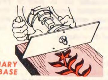
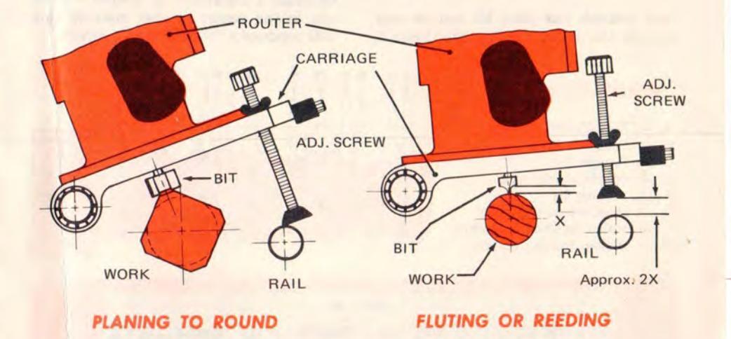
Taper Routing and Fluting
Tapered legs
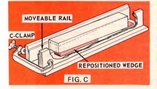
add grace and distinction to such projects as tables, chairs, bed-steads, etc. The tapering can be quickly and neatly done with a router and a simple fixture such as the one illustrated. This fixture consists of a base with two equal straightedge sides, one fixed onto the base and the other loose (to be held with clamps, as shown). The router will slide along the tops of the two sides (rails). The Router Crafter (page 34) does an even better job of tapering and fluting.
TAPERING
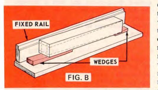
Make a 1/4-in. wide by 9/16-in. deep rabbet cut along the top inside edge of each fixture side rail. Attach the 5/8-in. O.D. guide bushing to your router ( page 16), and install a 1/2-in. straight bit.
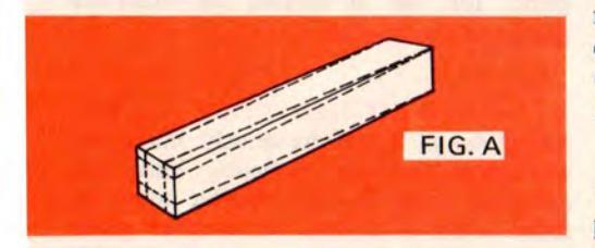
Use square stock and mark the taper lines on it ( fig. A ). Prepare two wedges which can be used under the workpiece ends to lift it up as required ( figs. B and C ). Position the workpiece on the fixture against the fixed side rail, and wedge up its ends so that the adjacent taper line for the top side will be exactly matched with the edge of the rabbet cut in this rail ( fig. B ). Clamp the moveable rail in place to hold the workpiece securely ... and check to make certain that its rabbet edge also matches the top taper line on this side of the workpiece.
Set the router for zero depth of cut at the low workpiece end ... then slide it along the rail tops to remove all stock that projects above the top taper lines. Do the remaining side tapers in the same way. Note, however, that when doing a taper opposite to one already cut, the wedges must be repositioned ( fig. C ).
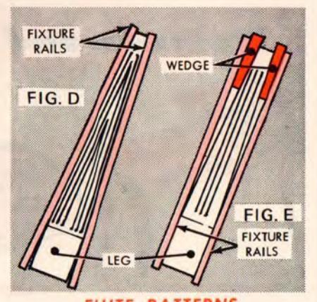
FLUTE PATTERNS
DECORATING A SQUARE OR RECTANGULAR WORKPIECE
Fluting (grooving) or beading (removing enough stock to leave ridges) adds a decorative touch . is easily done with above set-up.
The accompanying illustrations show flute patterns resulting from two different set-ups. In the first, the leg is wedged up at the small end and clamped between the two fixture rails (just as for tapering, preceding). Plough grooves, made by pressing your Edge Guide against the outer side of first one rail then the other (to make an equal number of grooves at each side of the leg) will result in long Vs. If centered, parallel grooves are desired, place wedges between the tapered end of the leg and the fixture rails so the rails will be parallel to each other. The grooves can be made to surface at one end, if desired, by slanting the leg slightly in the fixture.
Set up and flute or bead each of the four sides in the same manner. For fluting, use a small bit and adjust the Edge Guide to space the flutes evenly. For beading, use a larger bit to leave
square sided ridges, evenly spaced. Sand the ridge edges later to round them as desired. A straight, V-groove, veining (round end) or even a small dovetail bit can be used to good effect.
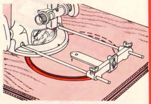
DECORATING A ROUND WORKPIECE
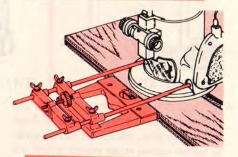
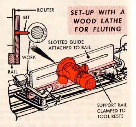
This is best done with the Router Crafter (page 34). However, if you have a wood lathe on which you have turned a cylindrical or a tapered-round leg and it has an indexing head — you can combine your router and the lathe to produce flutes or beads for decorating the leg. Two tool posts and a homemade guide rail are all you need.
Adjust the tool posts to hold the rail parallel to the leg with the centerline of the slot exactly parallel to the centerline of the leg. Now, when the router base is moved horizontally along the guide rail, the bit will travel through the slot at a 90° angle to the groove to be cut. Plan your indexing to space the grooves or beads evenly around the leg. Remember, however, if leg is tapered, the grooves will be more closely spaced at its small end than at its large end.
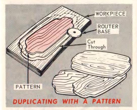
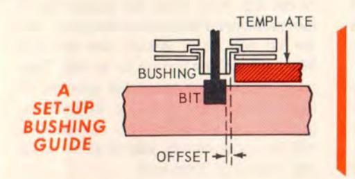
PATTERN DUPLICATI When the design calls-for an outline having long and "gentle" curves and/or straight areas, and you wish to make a number of duplicates, use of a pattern guide assures you of a quick, simple method. Since the edge of the router base rides against the pattern edge (accompanying illustration), the pattern must be enough smaller than the finished work to allow for the distance between the bit and the router base edge. Clamped to the stock, the pattern serves as an excellent guide for routing clear through the stock to cut it off to the outline desired. Such a pattern can also be used for grooving workpieces to duplicate decora
•USE OF A GUIDE BUSHING Any one of the three guide bushings (page 6) can be attached to the router base (with the three screws furnished with the bushings) as illustrated. The bushings have 7/16-, 5/8- and 1-1/16-in. O.D. pilots, respectively, for use with different bits and templates. Select the bushing and bit best suited for your template and type of cut you wish to make.
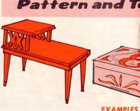
EXAMPLES
Duplicates are easily prepared, either by use of a pattern or a template. A pattern is a specially prepared guide made of plywood or hardboard. Templates are used in conjunction with one of the three Guide Bushings (page 5) available for
emplate ... Routing and Edging
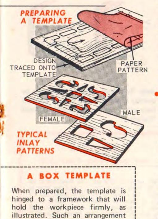
OF TEMPLATE ROUTING AND INLAY WORK
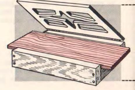
attachment to the Router Base. A template may be made of plywood, hardboard, or sheetmetal, and is generally used whenever intricate design work (such as required for inlaying or latticework) is to be done.
avoids the need for clamps, and
speeds production type work.
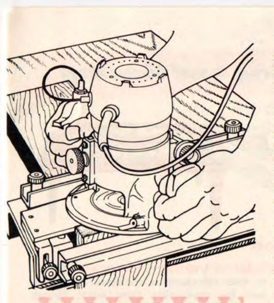
• MAKING AND USING A TEMPLATE A 1/8-in. thick sheetmetal or aluminum template is best for production type work, though plywood, hardboard, plastic, etc. may be used. Preparation of the template can be done with an electric saber saw or, if the material permits, by routing through along carefully traced pattern lines. Just remember when making the design to allow for the off-set between the router bit and the edge of the guide bushing you will use. After preparing the template, simply clamp it to a piece of stock and rout out your design using the template edges as your guide. If turns sharper than your guide bushing will make are desired, cut these out afterwards with a chisel.
LAY WORK Inlaying requires the use of two templates, one (male template) for preparing the inlay pieces and another (female template) for preparing the routedout spaces these are to occupy. The male template need provide for only each of the different shapes to be used, but these must be planned to be a hairline smaller than the female spaces into which they will fit. Prepare the male pieces by cutting clear through appropriate stock of 1/8 to 1/4-inch thickness ... then rout the female spaces into your workpiece about 1/64-inch deeper than this thickness. Glue the male pieces in place and, when dry, sand to a smooth surface finish. If wood is tastefully selected for colorings and grainings, really beautiful workpieces can be made in this manner.
Dovetail Jointing
All fine cabinetwork uses dovetail joints for joining drawer fronts (and sometimes the backs, too) to the sides ... and for other joints requiring the best of neatness and strength. But it is practically impossible for anyone other than a highly skilled cabinetmaker to prepare such a joint without using a dovetail bit and template. And your router is the
deal power tool for holding the bit. Indeed, this one use of the router alone makes it invaluable!
For 1/2-in. dovetailing you need the Dovetail Fixture and the Guide Bushings (page 6), and the 1/2-in. Dovetail Bit (page 4). For 1/4-in. dovetailing you need the fixture and the 1/4-in. template (furnished with guide bushing), and the 1/4-in. bit.
The fixture holds both workpieces so that both parts of the dovetail joint are cut simultaneously. Set-up is quick and simple. All you need do is guide the bit to follow the comb-like edge of the fixture template.
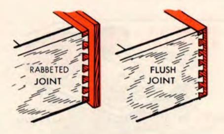
Both flush and rabbeted joints can be quickly made with this set up. Detailed instructions are packaged with Dovetail Fixture.

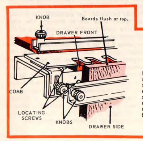
SETTING UP THE DOVETAIL TEMPLATE
Install workpieces inside out – the drawer front on top and the drawer side in front – and clamp firmly as shown. For dovetail at left side of drawer, butt left edges of workpieces against the two locating screws shown; for right side dovetail, use locating screws on right side of template. These screws are placed in different holes depending upon whether a flush or rabbeted dovetail is to be made.

The 3-section template can be set up for mortising both a door and the door jamb — for square- or round-cornered hinges up to 5-in. long. Set-up can be made for two or three hinges on doors 3/4- to 2-1/2-in. thick and up to 7 ft. high. Two or more identical doors can be hung with the same set-up ... and one of the three guides can also be used for mortising for standard-size lock faces and plates.
The Butt Hinge Templates (sold separately and also furnished with template at left) are used to mortise a door or a jamb for one hinge at a time. Two sizes are furnished: for 3-1/2- and 4-in. long hinges. The router must be fitted with a proper size Guide Bushing (page 6) to use any of these templates. Use the Hinge Mortising or a Straight Bit (page 4). Full instructions are packaged with the templates.
Laminated Plastics Cutting and Edging
Laminated plastics, phenolics and laminates having similar bonding agents are much too hard to be shaped successfully with ordinary tools. For fast, clean edging — without danger of chipping — a carbide-tipped bit should be used ... and the bit must be precisely guided in firm contact with the edge.
Professional quality trimming can be accomplished in two ways: 1) By using the Laminated Plastic Trimmer (page 6) and the Formica Trimmer that is supplied with it. 2) By using either the Veneer Trimmer or the 22° Flush Bevel Veneer Cutter (page 5).
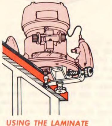
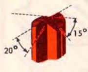
The laminated plastic trimmer and its bit offers the most versatility. First, the
combination 1-flute bit will trim either at a 20° bevel angle (if beveled bit end is used for cutting), or a straight, flush edge (if bit is lowered to use the straight portion). Second, the cutter attachment can be micro adjusted in or out to set the depth of cut as desired ... which means that, if it is advisable, you can do the trimming in two (or more) passes at staged depth-of-cut settings, instead of trimming off a sizeable overhang all in one pass.
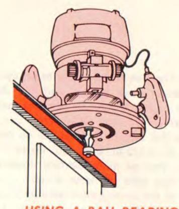
If you wish to do both flush and bevel trimming with the piloted type bit you will need both the flush and the 22° bevel bits. However, these bits do have 2 flutes (cut faster and smoother) — and the ball-bearing pilot is the best possible type of guide for following any edge contour.
With either above method the best practice is to pre-cut the laminating material so that it will overhang the wood to which it is bonded by about 1/8-in. on every side. After the bonding agent has set, use the router bit to trim off this 1/8-in. to make a flush or bevel-faced edge.
TRIMMER ATTACHMENT
PILOTED TRIMMER
Sharpening Bits and Cutters
A dull or chipped cutting edge makes fine work impossible. It makes the router difficult to hold to a true line, makes cutting slow ... and causes splintering and/or gouging. It may also overload the motor and, if used too long, may lessen the life of your tool. Altogether, the use of a dull or chipped cutter is extremely poor economy , especially when it is so easy to keep your bits and cutters razor sharp with this "foolproof" attachment.
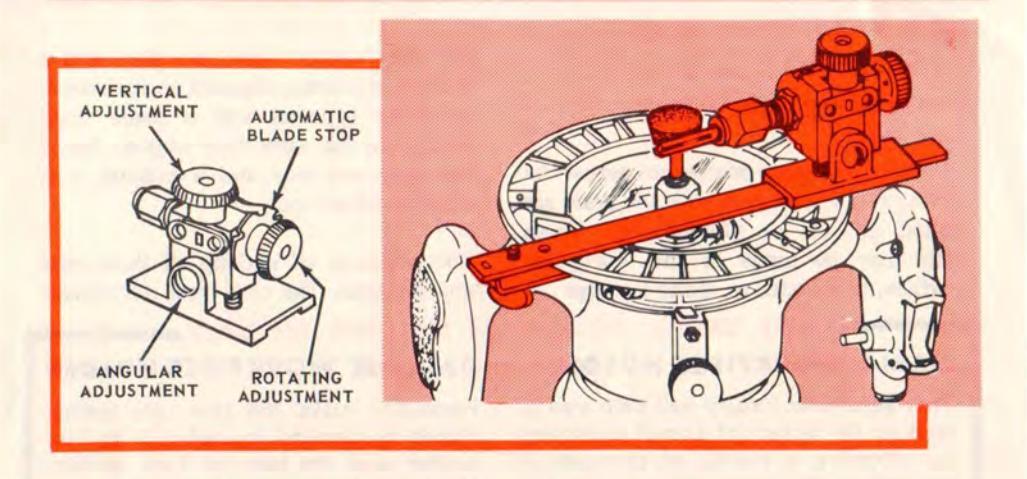
A special grinding wheel for use in the router chuck is included. A full range of circular and angular adjustments is provided so that you can accurately align any shape cutting edge with the grinding wheel surface. Once set for one edge of a two or three edged cutting tool these adjustments serve also to align the remaining edges so that all edges will be sharpened to identical proportions. A vernier type feeding screw (vertical adjustment) allows you to establish an exact setting for each successive pass of an edge over the grinding wheel . and a built-in automatic blade stop makes it
easy to rotate each edge in turn into exact position for a pass over the wheel. Thus, you sharpen the two or three edges of the cutting tool to one vernier setting (simply by sliding the attachment on its guide rail)... then repeat at as many additional vernier settings as required to make all edges equally sharp. Detailed instructions are packaged with the attachment.
Since metal removed from the outside of a bit changes its size, avoid sharpening on the outer surface more than absolutely necessary. Also sharpen end,
maintaining original bevels or as illustrated. Touch the edges around the outer surfaces lightly to remove burrs.
NOTE
All router bits and cutters may be sharpened with this attachment – excepting only the carbide-tipped bits (pages 5 and 22). These bits must be sharpened on a diamond wheel.
How to Rout Wood Joints
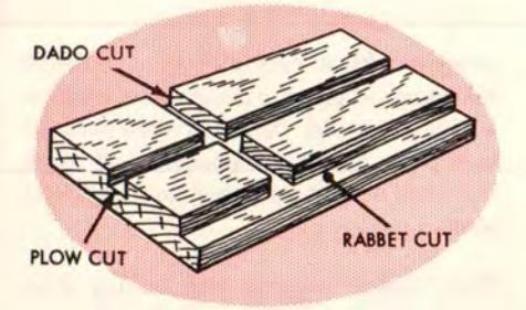
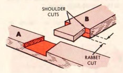
DADO, GROOVE AND RABBET CUTS
Description and Basic Set-Ups
A dado is a square groove cut across the grain, and similar cuts with the grain are called grooves or plough cuts. These cuts may be made in the workpiece surface, in its end, or along its edge ...
but they always have two sides and a bottom to form a channel in the wood. If either type of cut is made close enough to the workpiece edge so that it has only one side and a bottom it is called a rabbet cut.
The methods of making all three cuts are identical. The only real differences
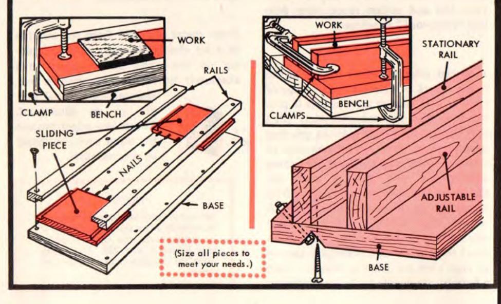
TWO USEFUL HOMEMADE HOLDING
SMALL WORKPIECE HOLDER
This adjustable fixture will help you to rout on the surface of a small workpiece by affording a means of clamping it securely to the bench. You can use 1/2to 1-in. lumber as desired ... and can size the pieces to suit your requirements. Make identical rabbets on the two sliding pieces and the two rails so that adjustment will be smooth and free. Drive 1-1/2-in. finishing nails about 1-1/4-in. deep into the sliding pieces as shown — then cut off the heads to leave sharp points. These will grip the workpiece, and the holes can be patched afterwards.
ON-EDGE WORKPIECE HOLDER
Preferably make the two rails (which should be identical in size) of 1- to 2-in. lumber and the base of 1-in. lumber. Make the fixture length and the base width to suit your requirements. Support the stationary rail as shown — it must be rigid . For use, clamp in the workpiece and clamp the fixture to your bench as illustrated. Having the tops of the two rails identical (and flat) will not only provide a support for the router base to slide along... it will also allow you to set your edge guide to measure in accurately from the two sides of the workpiece.
between them are due to the locations of the cuts (in surface, edge or end) – which, of course, determine how the workpiece is to be held.
For making surface cuts (dados, ploughs or rabbets) secure the workpiece firmly, flat on your bench or other substantial support, so it can't slide or wobble. Use the Edge Guide, a straightedge, the tee square, the box guide, or any suitable method for making a straight cut. For long, through cuts a Shaper Table (page 7) is most helpful.
For making end or edge cuts (dados, ploughs or rabbets) secure the workpiece in an On-Edge Holder (preceding page) ... or clamp it in a vise between two equal thickness straightedge scrap pieces on which the router base will slide accurately. Use the Edge Guide pressed against the outer side of one (or the other) scrap block to guide the cut.
Through and Blind Cuts
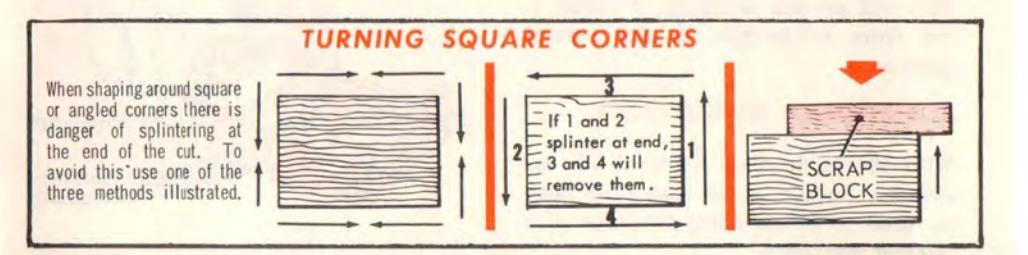
Dados and ploughs are said to be through cuts if they extend from one workpiece edge to the other. When making such a cut across the grain, back up your workpiece with a scrap block to prevent splintering out the wood at the end of the dado. (This also applies when rabbeting across the grain.)
The cut is called half-blind if it stops short of the far edge; is called a blind cut if it both starts and stops short of the edges. To make a half-blind cut, start at the edge and have a stop block clamped to the work to stop the router when desired. To make a blind cut, use a stop block or a mark to locate the starting point — and lower the router so as to drill a starting hole at this point. Finish the cut as for a half-blind one.
Wide and/or Deep Cuts
If a cut is to be wider than your largest bit, do it by making successive passes each time readjusting your guide so that the next cut overlaps the previous one by about 1/16 to 1/8 inch. For a deep cut also make successive passes, lowering the bit a reasonable amount for each

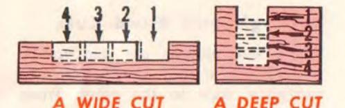
new pass. When the cut is both wide and deep, do all the cutting at one depth, then proceed to the next depth.
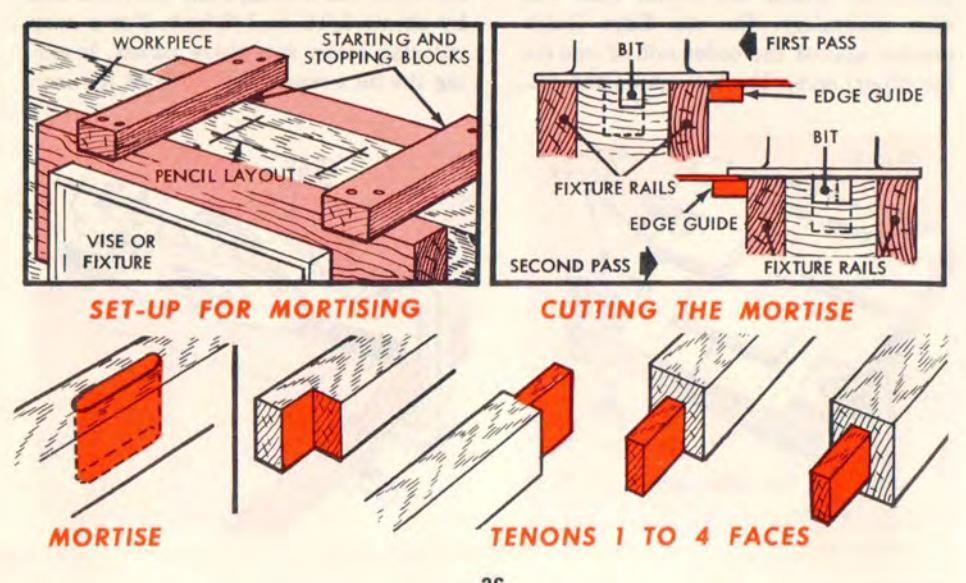
MORTISE AND TENON CUTS
A mortise is simply a deep, blind dado or plough cut — and a tenon is formed by rabbeting one, two, three or four edges (according to the type of joint desired) of the mating workpiece. The only "trick" involved is to make your mortise and tenon fit together. This requires careful measurement and precise workmanship.
scrap blocks at each side of it if this is necessary to provide an overall width on which the router base can slide without wobbling. Carefully measure and mark the mortise area in pencil on the workpiece.
Now, clamp starting and ending stop blocks in place as for a blind dado cut. Next, install and adjust your Edge Guide so that one side of the first pass will be properly located along one side line of the mortise area. Start the router and make this first pass...then make a second pass with the Edge Guide pressing against the opposite side. You'll now have a shallow cut covering the whole mortise area and exactly centered between the workpiece sides. Proceed to deepen it as required in the usual manner.
A Centered Mortise
Select a bit about 3/4 the size of the width of cut to be made. Adjust it to a reasonable depth of cut. Set your workpiece up in your "On-Edge" holding fixture or a vise, using equal thickness
An Off-Center Mortise
This is cut in exactly the same manner excepting that it is better to do it by using the Edge Guide along one side only, if possible. If it isn't too wide, use a bit the exact width of the mortise so
that one pass at each depth setting will suffice. If it is too wide for this, you'll have to make two or more passes at each depth setting, readjusting the Edge Guide for each.
A Centered, Four-Faced Tenon
This is the most commonly used type as it completely hides the mortise cut when the joint is assembled. There are two methods of setting up to make the cuts.
For the first method start with the same set-up as for the centered mortise. If possible, select a bit wide enough to exceed the width of cut required by 1/16 inch or more. Adjust your Edge Guide so that the cut will travel along your marked tenon line at one side (and overlap into the scrap boards at the side). Make one pass at each side leaving a perfectly centered shallow tenon ... then proceed to deepen as required. You now have a two-faced, centered tenon. To make the other two faces, turn the workpiece edgewise in your holding fixture ... and repeat the preceding steps.
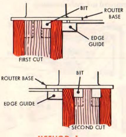
METHOD 1
NOTE
Sometimes the second two (on-edge) faces are made deeper or shallower than the first two (flat) faces. This, of course, would require a different Edge Guide setting ... and choice of a different size bit.
***************************************
If your bit isn't big enough to cut the full width of each face in one pass, preferably cut each face down to proper depth, placing your cuts right along the tenon outline (and leaving the uncut wood around the outer edges). The uncut wood can now be removed on a bench saw without touching the finished tenon at center.
NOTE
Any reasonable number of workpieces can be simultaneously held in your fixture and cut, using this method.
For the second method, lay out your several work pieces as illustrated, clamping them securely to prevent wobble. Preferably use a straightedge guide ... and simply make enough passes (re-locating the guide each time) to complete the rabbet cut that makes the first face of each tenon. Keeping the same depth adjustment, turn the boards to do the opposite face. Then do the remaining two faces in the same manner.
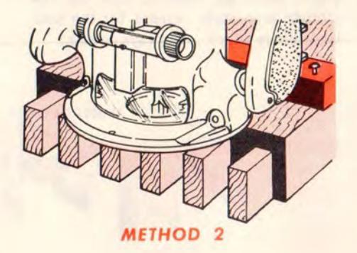
This method has the advantage (as a rule) of not requiring very deep cuts, so that one depth setting only is sufficient. But it has these disadvantages: The workpieces must be very securely held ... care must be taken not to let the router dip down and round off the end pieces (best use scrap boards at the ends) ... and it is more difficult to accurately locate the straightedge for each pass.
Other Types of Tenons
Tenons also are made with only one,
two or three faces — and with faces of varying widths, depending upon project requirements. The same two methods apply for making these variations.
NOTE
All routed mortises will have rounded corners (to the radius of the bit)...and all tenons (however cut) have square corners. It is easiest to round off the tenon corners to fit, using a file or rasp; but the mortise corners can be squared with a chisel, if preferred. Also, have a tenon about 1/64-in. short of mortise depth – to allow glue space.
33 COMMON WOOD JOINTS FOR YOU TO ROUT
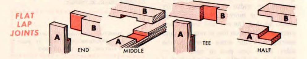
END-, MIDDLE-, TEE- AND HALF-LAP JOINTS
Flat Types
In all of these joints, both pieces (A and B) will have identical rabbet and/or dado cuts ... providing both pieces are the same width. In this case, cut both pieces simultaneously by laying them side-by-side (as for Method 2 Tenon Cutting). If the pieces are of different width you'll have to measure and cut the rabbets separately (except for the halflap rabbets which are always equal).
On-Edge Types
These are similar to the above. They, also, can be cut simultaneously (with pieces stacked on their edges) if boards are of equal thickness. For all but the half lap, however, if boards are of unequal thicknesses each cut must be measured and made separately.

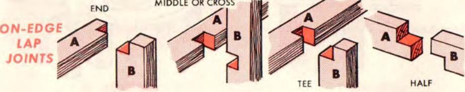
MIDDLE-LAP ON EDGE WITH GROOVE
The cut in piece A must be made with board on edge (to obtain a square bottom)... and so must the mating cut in B. Make these to the same depth (x) equal to 1/2 the B piece width — and cut them simultaneously using a bit having a diameter equal to width z. Afterwards, make a second pass through piece B (only) to widen its cut x to the thickness of piece A. Last, cut the two side dados in piece B, gauging the depth (equal at each side) so that width z remaining will equal the width of the cut in A.
tioned for each side line cut. Last, make the shoulder cuts in B, preferably with a very thin saw followed by chiseling out the sharp angles.
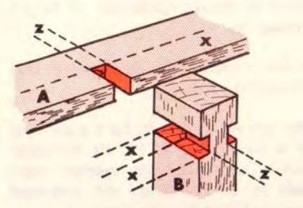
COGGED JOINT
Reinforcing strips are often fitted to main frame members by this joint. With A on edge, dado its slot making it 1/3 as wide as thickness of B, and 1/2 as deep as the width of A. Now dado the two slots in B (cutting in the directions of the arrows) using the same depth adjustment and leaving the uncut center the same width as the slot in A. Square the corners of these two cuts with a chisel.
BOX JOINI
EDGE GUIDE GUIDE FIXTURE BOX JOINT
Stronger than a glued miter or plain drawer joint, this is used principally in box and crate construction ... sometimes for drawers. Divide the width of your workpieces (A and B) into a
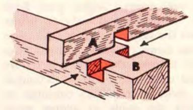
DOVETAIL LAP
This is a strong "push or pull" joint; but requires careful layout. A and B should be the same thickness. First, make the rabbet cut in B as you would an ordinary end lap, cutting to a depth 1/2 the board thickness. Using this same depth setting, cut the wedge groove in A ... by first dadoing along each side line and afterwards cleaning out the middle. Your straightedge guide must be reposi-
number of equal segments. Prepare two scrap blocks each the width of a segment, and set up your workpieces as illustrated. If you have a bit the exact diameter of a segment width, use this ... each cut can then be made in one pass. (Otherwise, select a smaller bit and make two passes.) Adjust your Edge Guide for cut 1 and make it. Either readjust the Edge Guide or place a piece of scrap (same thickness as other scrap blocks) between the guide and fixture ... and make cut 2. For cut 3 (and as many more as required) continue readjusting the guide or adding equal thicknesses of scrap to space it out from the fixture.
THE VARIOUS DADO JOINTS
We list below six different dado joints. These vary in strength (as is obvious) and in application. In general, however, the first four types are used for installing shelves, drawer bottoms and similar suspended members which are usually supported at the ends (or the ends and one or both sides). The last two types make neat and strong corner joints for boxes, drawers, etc. if A is the front piece which will be pulled on.
The plain dado simply calls for a dado cut in B the thickness of A, and to depth as desired (generally 1/3 to 1/2 through B).
A drawer dado is the same, except that B is rabbet cut to fit.
The housed dado calls for a rabbet cut in A (about 1/4 to 1/2 its thickness) with a correspondingly smaller width dado in B. This joint will withstand swaying better than the first two.
Best of the shelf joints is the dovetail dado ... it withstands swaying and pulling out of the side supports (B). Use a 1/2-inch or larger dado bit. Make dado cut x in B. Next, set up A for an end cut. Use the same bit and depth setting to make the cut in A... but allow only 1/2 (exactly) the diameter of the bit to be used in making this cut. Last, use a straight bit and the same depth setting to dado cut the bottom straight side of the slot in B, widening this slot to the required thickness for A.
The simple box corner is made the same as the housed dado above.
A milled box corner is started by
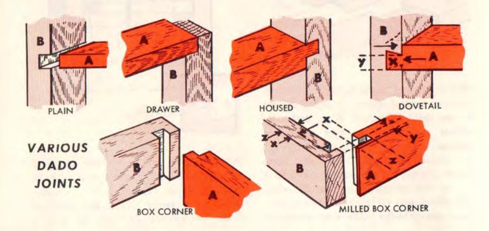
making the same two cuts as for a box corner. Dimension y should be about 1/3 the thickness of A, and the lip at the end of A should be as thin as possible (to show very little end grain when assembled) ... so gauge the width and placement of the slot in B accordingly. The width of the rabbet (x) in A will be the thickness of B less the depth of the slot cut in B ... and will be as deep as possible (per the above). Last, turn A on end to dado cut the slot y ... to exactly mate with the lip left at the end of B.
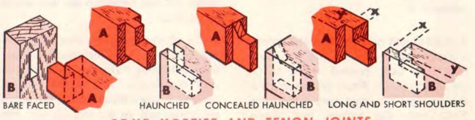
THE VARIOUS MORTISE AND TENON JOINTS
We show eight additional popular joints in this group. In most cases the mortise (or mortises) is cut exactly as previously described. All the tenons are also shaped as previously described, with the following variations.
NOTE
If you have learned to measure with extreme accuracy, much time can be saved in production work of centered mortises by selecting a bit 1/3 or slightly more the thickness of B. The mortise is then cut with just one Edge Guide setting – at exact center ... and the same bit will clean out all the wood at each side of the tenon, with one guide setting.
The bare-faced tenon is actually a two-
faced one having one side and one
shoulder face. These can be the same thickness to save time. This joint is often employed when setting chair rungs into the legs, the two faces being at bottom and inside where screws can be installed through them into the leg for added strength. Also used — with faces at top and inside — for joining a table skirt to the leg ... or any narrower board to a thicker one.
Haunched tenons are also used in joining table skirts to legs — since the top is hidden. Tongue and grooved members are also joined in this manner (in which case the shallow part of B mortise is already there). Notch the tenon of A (with a saw) to match the mortise in B.
A concealed haunched tenon is like the above, except that the tenon is cut off so as not to show on top. Use this for more tenon strength when the width of A is too little to allow for simple tenon of sufficient strength. To rout the slant portion of the mortise in B, set B in your vise at an angle — after the square portion of the mortise has been cut.
The long and short shoulders tenon is made by first preparing A and B for a bare-faced tenon ... then by rabbeting the uncut face of A and opposite face of B to proper width and depth. This joint is used principally to join a piece (A) to a rabbeted one (in which case the rabbet in B is already there).
OME MORTISE AND TENON JOINTS
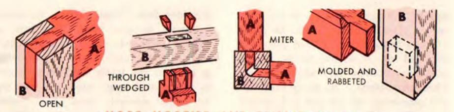
MORE MORTISE AND TENON JOINTS
An open tenon — used in rough carpentry work and for window screens, etc. — does not have an actual mortise. The "mortise" is most easily made by setting B on end and ploughing a deep slot.
For a through-wedged tenon simply cut the mortise clear through B, then flare it out to greater width at top by tilting the router as required. The flare at each side must equal the maximum thickness of one wedge minus the thickness of one of the saw cut slots in the tenon. Cut each wedge with a slight bow on one side and a straight taper on the other. This, also, is a rough carpentry joint very strong. A neater appearing variation of it can be made by not cutting the mortise clear through B... in which case it is assembled by starting the wedges in their slots, then hammering A and B together.
The mitered tenon is useful for joining two parts (A) to one part (B) that is too small to offer strong support without this arrangement. The mortises in B meet (at a 90° angle) inside — and the tenon ends are mitered (by sawing) so that gluing will join them together inside of B.
A molded and rabbeted tenon is merely a simple tenon used to join two members that have molded edges (as in picture framing). Whatever the shape of the molding the treatment is the same. First make the mortise and tenon. Afterwards, mark and miter saw each
molding so that when A and B are joined their moldings will-join in a simple mitered corner.
TONGUE AND GROOVE JOINT
Commonly used for joining boards along their sides and ends to build up large areas (such as a floor), this is actually a tenon-type joint. The tongue is cut just as you'd cut a two-face centered tenon... the full length of the board. The mating groove is a plough cut (also the full board length) centered in the same manner used for a centered mortise.
THE MITERED JOINTS
We illustrate here four common variations of the simple miter used for added strength while preserving a neatness suitable for the finest cabinetwork. The "miter portion" of these joints must be saw cut (very accurately, if joint is to be neat); but the variations are best added by routing.
For a slip-feather miter first miter the two boards ... then lock them together in your holding fixture so that you can rout the feather slot in both simultaneously. Use a bit about 1/3 the board thickness, and go as deep as you like (considering appearance and strength).
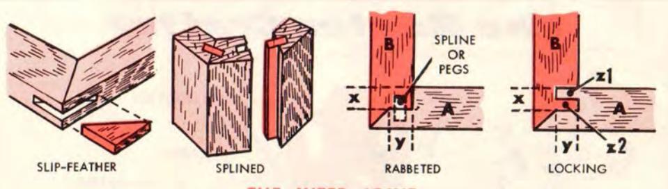
THE MITER JOINT
Saw cut the feather to proper thickness, but otherwise somewhat oversize. Its edges can be sanded down after the glue has set — will be barely visible.
The splined miter is also made by first mitering both boards. Afterwards, plough cut the grooves. Use the same technique as for a tongue and groove plough cut, but block your workpiece in the holding fixture at the correct angle to make the plough cut at a 90° angle to the mitered edge face. Saw cut the spline piece to fit neatly, allowing about 1/64 inch slop for gluing space.
To make the rabbeted miter first rabbet cut the end of each board (A and B). Rabbet x in A must be as deep as half the thickness of A and as wide as the thickness of B. Rabbet y in B must be as deep as half the thickness of B and as wide as half the thickness of A. Best lay out these cuts in pencil before making them - and allow extra at the board ends to be cut off when mitering. With the rabbets cut, saw cut the miters. staving on the outer sides of your pencil lines and taking care not to cut into the "hump" on B. You can now either cut ploughs for a spline or drill a series of holes to take small dowel pegs . .. either way you'll have a strong joint.
The locking miter is much like the above. Rabbet x in A must be as deep as
half the thickness of A and as wide as half the thickness of B. Rabbet y in B must be as deep as half the thickness of B and as wide as half the thickness of A. After the rabbets and miters are cut, plough cut the two grooves (z1 in B and z2 in A) making each as wide as one-fourth the thickness of A and as deep as half the thickness of B.
LOCK JOINT
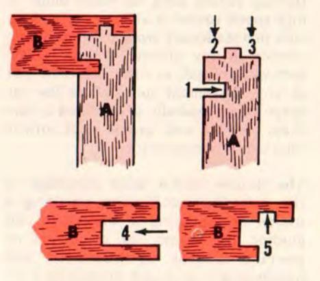
This is one of the firmest of all cabinet joints, with strength in all directions. All of the cuts are simple dado or plough cuts, easily made if you first lay out the lines accurately in pencil using careful measurements. With the layout marked, make the five cuts in the sequence and directions shown in the illustration. Slide the two pieces together for assembly.
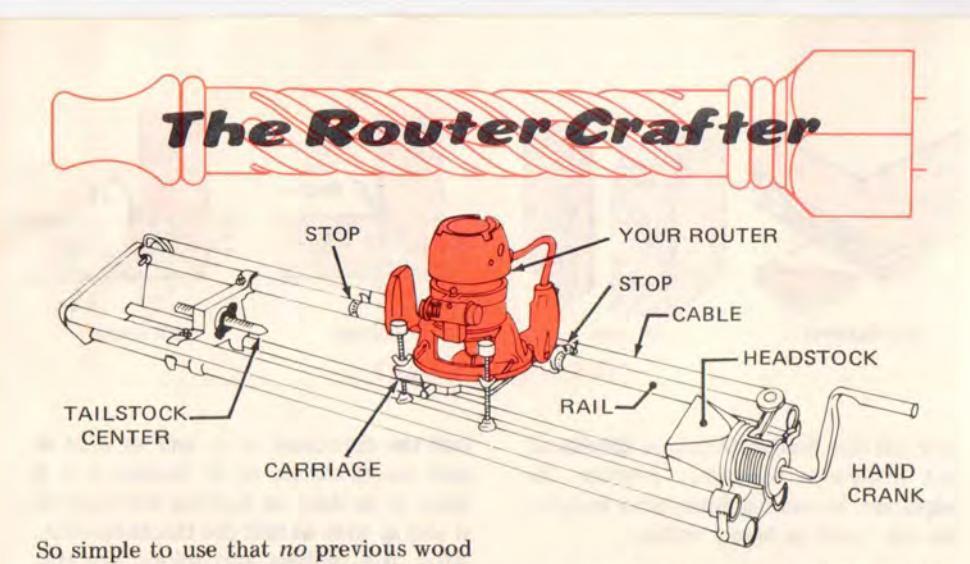
turning experience is required, the Router Crafter makes it easy to produce a greater variety of spindle turning and carving designs than are possible with a wood lathe designed for homeshop use. A lathe is limited to cuts made while the workpiece is rotating, and careful shaping of these cuts requires operator expertise in the handling of the woodturning chisels used to make them. A high-speed router is able to make clean cuts in a stationary workpiece, or in one rotated in any manner desired (all or part-way around, in either direction and at any convenient speed), and the cut shape is mechanically determined by the shape of bit and preset depth-of-cut selected by the operator.
The Router Crafter takes advantage of the router's versatility by providing a means of mounting a workpiece and guiding the router for a number of precise shaping operations. It will handle square or round workpieces 1- to 3-in. thick with a work area up to 36-in. long.
HOW ROUTER CRAFTER WORKS
The workpiece is mounted between two centers. One, in the "headstock", can be revolved by a hand crank to rotate the workpiece as desired — or, you can use the built-in indexing feature to lock the workpiece so that 1, 2, 3, 4, 6, 8, 12 or 24 evenly-spaced arcs of its circumfer-
ence are positioned for shaping. The other center, in the adjustable "tailstock" can be positioned to accommodate various length workpieces and can also be adjusted to place this workpiece end on-center or off-center with respect to the headstock end (for straight- or tapered-spindle shaping).
Your router is mounted on a carriage that can be pivoted up to lift the bit from the workpiece or lowered to an adjustable down position which, in combination with the router's adjustment feature, will determine the depth of cut to be made. This carriage is free to travel on a rail parallel to the workpiece centerline, and can be moved freely by hand to right or left for shaping any desired lengthwise portion of the workpiece. Adjustable stops on the rail can be set to hold the carriage stationary or to exactly limit its travel as desired. The carriage also can be secured to a cable which will pull the carriage along the rail as the headstock is rotated. Cable movement of the carriage is in fixed, uniform relation to the headstock rotation so that precisely pitched spirals can be cut simply by rotating the workpiece with the hand crank. Moreover, use of the previously mentioned indexing feature allows you to cut 2 to 24 different spirals evenly spaced around the workpiece (for roping effects) ... and spirals can be left-hand (advancing from bottom to
top) or right-hand (from top to bottom), or a combination of both (to produce a diamond or effect).
MAKING VARIOUS CUTS
Planing Operations
Whatever its cross-section shape is in the beginning, a workpiece can be surface planed in a lengthwise direction to reduce part or all of it (except at the headstock end, as previously noted) to a perfect round or a shape having 4, 6, 8, 12 or 24 equal sides (like a square, hexagon, etc.). The Craftsman Rabbeting and Surfacing Bit (page 4) is used, without the pilot. and maximum width-of-cut is 15/16 in.
To make a square the indexing feature is used to expose four equally-spaced sides of the workpiece in sequence for cutting — and each side is planed, down to the maximum desired depth, by hand traveling the carriage and router. In similar manner, 6, 8, etc. equally-indexed sides can be planed to produce a hexagon, octagon, etc. For rounding, this method is used to first plane 24 equal sides, then the resulting small "flats" are removed by rotating the workpiece (with the crank) while slowly pushing the router lengthwise for a final pass.
Some novel cross-section shapes can be
created by varying the maximum depthof-cut when finishing different sides. In addition, these planing operations can be used for tapering, by off-centering the tailstock. Tapers of up to 1 in. difference between spindle thickness at its two ends can be planed while rounding, squaring, etc. all or any portion of a spindle.
Reeding and Fluting
Reeding is a series of parallel lengthwise beads; fluting, a series of parallel lengthwise grooves. Selection of a bit depends upon the shape of the bead or groove desired — any one of the one-piece bits (pages 4 and 5) can be used, singly or in combination with others. Beads (or grooves) generally are equally spaced, but any desired spacing pattern can be used. The operation is the same as for lengthwise planing a square or hexagon, etc. — and the workpiece is indexed to provide the desired spacing.
When reeding or fluting a round or tapered round spindle, one maximum depth-of-cut setting produces equal height beads (or equal depth grooves). This is also true for other shapes (squares, hexagons, etc.) if all cuts are at the centers of the sides. Cuts that are not centered will be different in depth and in angle of approach, thus affording some novel effects.
35
The Router Crafter (con't.)
Contour Shaping
Lengthwise curves (concave and/or convex) and flats, that do not change too abruptly to be traversed by the template follower, can be shaped in the same way used for lengthwise planing and/or rounding, except that a pattern is attached to the front of the Router Crafter so that the template follower will contact its top edge and lift or lower the carriage as the carriage is hand moved from left to right. A great variety of shapes (including half- or quarterround posts) can be created - and easily duplicated - in this manner. The Craftsman Core Box Bit (page 4) is used.
Circular Beads, Coves and Shoulders
Different one-piece bits (pages 4 and 5) can be used to create various shapes around a spindle circumference, as illustrated. For each specific cut the carriage is held stationary - by the stop at each side on the rail - and the workpiece is revolved by turning the hand crank. There is no limit to the variety of bits that can be used - at varying depthsof-cuts - for creating circular contours.
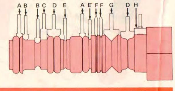
Spiral (Roping) Cuts
Any suitable one-piece bit can be used, though the Point Cutting Bits (page 4)
- A Point-Cutting 1/4-Rd.
- B Core-Box Bit
- C Straight Bit
- D Point-Cutting Ogee
- E Veining Bit
- F Double-End V-Groove
- G V-Groove Chamfering Bit
- H Rabbet and Surface Bit

are generally preferred. For this operation the carriage is secured to the cable so it will travel left-to-right in fixed relationship as the workpiece is revolved by the hand crank. Different bits, depths-of-cut, and indexing selections produce different "roping" effects also, spiraling can be done left- or righthand... or both, to result in a diamond.
Carving
With any type of one-piece bit desired cuts of predetermined lengthwise duration can be made to any predetermined depth. Any one or more of the preceding operations can, therefore, be used to decorate a workpiece as desired - or to cut to the center so that meeting cuts will produce a "see-through" effect.
SEARS, ROEBUCK AND CO. - CHICAGO, ILL. 60684 - U.S.A. AND SIMPSONS-SEARS LIMITED - TORONTO


 Loading...