

Sharpening Bits and Cutters

THE ATTACHMENT
For smooth, free cutting your bits must be sharp and clean. Use Craftsman Gum and Pitch Remover — which also inhibits rusting — for quick, easy cleaning. Use the Craftsman Cutter Grinding Attachment, which fits onto your router as illustrated, for precision sharpening of any of your bits. This attachment is furnished with two
grinding wheels: a white-colored wheel for sharpening high-speed steel bits; a greencolored wheel for sharpening carbidetipped bits.
The attachment Owner's Manual provides complete instructions for setting-up and using the attachment. Following is a general explanation of the bit-sharpening operations.
Regardless of the bit shape, the attachment can be adjusted so that each bit cutting edge, in turn, will be correctly in contact with the top surface of the grinding wheel. Use only the top wheel surface; make certain that only the one bit edge to be sharpened is in contact with the wheel. Do all sharpening on the flat (leading side) of a cutting edge... never grind the shoulder (outer side) nor the trailing side of a cutting edge.
The accompanying illustrations show how typical bit shapes must be positioned. To achieve proper bit positioning, one or more attachment adjustments are required.

SOLD BY SEARS, ROEBUCK AND CO. – CHICAGO, ILL. 60684 – U.S.A. AND SIMPSONS-SEARS LIMITED – TORONTO
DO MORE WITH YOUR
HOW TO

OVER 50 OPERATIONS DESCRIBED AND ILLUSTRATED

For Complete Router and Accessory Operating Instructions Obtain Sears Book: Power Tool Know How – The Power Router, Cat. No. 9-2949
Index
| PA | GE | |
|---|---|---|
| THE POWER ROUTER | 3 | |
| BOUTER BITS AND THEIR USES | ••• | 4 |
| POLITER ACCESSORIES | •• | 4 |
| • • | 6 | |
| GENERAL ROUTING INSTRUCTIONS | • • | 7 |
| STRAIGHT LINE ROUTING & EDGING | • | 10 |
| CIRCLE & CONTOUR EDGING & ROUTING | 12 | |
| LETTERING & CARVING | 14 | |
| HOLDING SMALL WORKPIECES | 15 | |
| PATTERN & TEMPLATE BOUTING & EDGING | 16 | |
| TAPER BOUTING & FLUTING | 18 | |
| • • | 20 | |
| • • | 20 | |
| LAWINATED PLASTICS EDGING | • • | 22 |
| BUTT HINGE MORTISE ROUTING | 23 | |
| SHAPER-TABLE ROUTING & EDGING OPERATIONS | 24 | |
| THE ROUTER CRAFTER | 26 | |
| How Router Crafter Works | 26 | |
| Cutting Procedures | 27 | |
| Workpiece Preparation | 28 | |
| The Bits to Use | 29 | |
| Planning a Workpiece | • • | 20 |
| Dimensions to be Considered Whee Planning | • • | 20 |
| • • | 30 | |
| Some Helpful Planning Factors | • • | 31 |
| Working Plan that Requires a Template | 31 | |
| SHARPENING BITS & CUTTERS | 32 | |
THE Power Router ...
A MULTI-PURPOSE TOOL
A power router serves the purpose of a wood chisel by providing an electrically powered means of chiseling out recessed areas to desired depth in a wooden-workpiece surface. It also serves as a carving tool with which designs can be either indented or raised on a workpiece surface. Indented grooves — straight or curved as desired — as small as 1/8-in. wide and from 1/64-in. to over 1-in. deep can be carved to form designs or to outline an area; or all the wood from a given area (to similar depths) can be removed, to leave a recess or create a raised panel of shape and size as desired.
In addition, a router can be used as a shaper for creating decorative edges — both external and internal edges — for making decoratively-shaped grooves (V, rounded, etc.), rosettes and carvings...and, with the proper attachments, for indent lettering, inlaying, design copying, dovetailing and other operations — and, most important, for carving tapered and/or highly decorative spindles of types which cannot be duplicated with an ordinary wood lathe.
Two popular Craftsman models are shown. Refer to a current Sears catalog.

NOTE
All operations explained in this book can be performed with any Sears Router equipped with the accessories designed and sold for use with the router.
Read the complete Safe Operating Instructions in the Owner's Manual packaged with your tool.
- DO Disconnect the tool from power source when installing or removing router bits and tighten the chuck securely after installing a bit.
- DO NOT Make any adjustments of your tool or workpiece while the tool is running.
- DO Keep your tool, motor and cutters clean. DO NOT Use dull, rusted, bent or gummed bits -
- or allow sawdust to clog the tool motor air vents.
- O Make certain that your workpiece cannot move during an operation.
- DNOT Attempt to hold workpiece with one hand while guiding the tool with your other hand.
- O Keep a firm, two-handed hold on your tool throughout each operation.
- NOT Let your attention stray, or handle your tool carelessly.
CRAFTSMAN HANDBOOK
PREPARED FOR SEARS, ROEBUCK AND CO.
© Midwest Technical Publications, 1977
Catalog No. 2948
rinted in U.S.A
Router Bits .... and Their Uses
The following illustrates and explains the various shapes of router bits, with which you can accomplish grooving, mortising, edging, etc. Customary sizes of each type. where appropriate are also shown Please keep in mind, however, that you must refer to a Sears Catalog for shapes and sizes currently available – there may be other shapes and sizes not listed here.
Many of these bits are available both in Kromedge high-speed steel and in Carbidetool steel. Kromedge types have specially
chrome-impregnated surfaces to resist rust and gum build-up for clean, fast cutting in all kinds of wood. The Carbide-Tipped bits (more expensive) are even faster and cleaner cutting, can be used for cutting harder (than wood) composite materials, and will stay sharp up to 15 times longer (when used on softwoods). All one-piece bits have 1/4-in. diameter shanks: the "winged" bits (for edge shaping) require use of the appropriate-type arbor (which serves as the shaft and provides a pilot for guiding the bit along an edge).

STRAIGHT BITS Single-flute, bottom- and sidecutting bits for routing flatbottom grooves and for mortising, carving or indenting. Sizes 1/4-,

V-GROOVE CHAMFERING Designed for routing vee-bottom,
1/2-in. top width, depending upon depth-of-cut. Size 1/2-in.
FORMICA TRIMMER
(or similar laminates), either straight and flush with workpiece edge or flush and at a 22° bevel angle. Must be used only with the (pages 6 and 22).
PILOTED STRAIGHT AND 22° FORMICA TRIMMERS
bits do not require a guiding accessory. One flush with workpiece edge; the other, a 22°
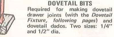
This 1/2-in. bit is used with the Dovetail Fixture (pages 6 and 20) for making interlocking dovetail joints such as required for fine
DOVETAIL BIT
COMBINATION PANEL CUTTER This 3/8-in. diameter bit is designed especially for drilling through a workpiece, then
BUTT-HINGE MORTISING BIT
This is a fast-cutting, 1/2-in. diamortising and operations like panel-raising or indenting that require much stock removal. Makes
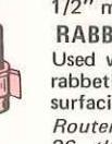
RABBETING/SUBFACING BIT
Designed especially for rabbeting this bit will cut rabbets up to 3/8-in. wide by 5/16-in. deep in one pass. For rabbeting, must be used with arbor and pilot, next page - or can be used without a pilot for surfacing.
COVE/CHAMFERING
These side-cutting bits must be used with the arbor and a pilot (next page) - and are used for cove-cutting a workpiece edge. Sizes: 3/8-in, and 1/2-in. (diameters) for cuts of these widths.
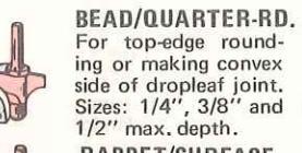
BEAD/QUARTER-ROUND
These, also, are side-cutting bits to be used with the arbor and a pilot. The two sizes, 3/8-in. and 1/2-in. will cut quarter-round beaded shapes to these widths.

grooves, rabbets and dados and
Round on bottom for decorative making small coves, etc. Five sizes: 1/16", 1/8", 3/16", 7/32"
DOVETAIL BITS
HINGE-MORTISING BIT
Special design 1/2" dia. bit for
quick, clean cutting of hinge
V-GROOVE
CHAMFERING BITS
For cutting V-grooves or cham-
fered edges, and for decorative
carving. Two sizes: 1/2" and 7/8"
CORE-BOX BIT
For fluting, carving and contour
turning on the Router Crafter
POINT-CUTTING
Templates, page 6 and 23).


For decorative grooving, carving, beading and roping - with the Router Crafter (pages 26 thru
OGEE BIT
Also for decorative grooving, carving, beading and roping with the Router Crafter (pages 26 thru
ARBORS FOR WINGED BITS
The arbor at left, for Kromedge bits, includes a 5/16-in, and a 7/16-in. pilot. The one at right, for Carbide-Tipped bits, has 1/2-in. and 5/8-in. ball-bearing pilots.

SPECIAL CARVING BITS Double-end bits each provide two different types of grooves. One for cutting 45° or 60° vee grooves; the other for cutting 1/16" straight or 1/16" veining


For making rounded edge decora-
For making recessed Ogee edge decoration as shown. Two sizes: 5/32'' and 9/32'' depth-of-cut.

For chamfering thick edges or bevel-edge panel raising when rabbeting bit is used for second cut. Size: 1/2" x 45° max. cut.
CHAMFERING RIT

Used with a pilot for surfacing or use with Router Crafter (pages 26 thru 31). Size: 15/16'' dia. Cuts 1/4", 5/16" or 3/8"

polyethylene case has storage space for up to 44 of your router bits - provides a safe, convenient storage.


DOVETAIL FIXTURE

a guide. See page
TRAMME
LAMINATE TRIMMER
toughest laminates. See page 22.

Use contour finger to follow along curved edge; use guide plate for any straight edge, or remove plate to follow a circular edge (see page 10-2). Also available without micro. adi.
Guides router to swing a perfect for circle grooving, edging or cut-outs. See page 13.
LETTERING TEMPLATE

Three-section template for 3 hinge mortises on door and on jamb for doors 3/4 to 2-1/2-in. thick, up to 7 ft. tall. For 3-1/2- and 4-in. butt hinges. Also, single
BUTT
TEMPLATE
Makes it easy to edge or Carbide-

ROUT-A-FORM
M
General Routing Instructions
IMPORTANT: The whole "secret" of professional routing and edge shaping lies in selecting the proper rate-of-feed ... and in making a careful set-up for the cut to be made.
Clean, smooth routing and edge shaping can be done only when the bit is revolving at a relatively high speed and is taking very small bits to produce tiny, cleanly severed chips. If the router is forced to move forward at a fast pace, the rpm of the bit is slower than normal in relation to its forward movement - and the bit must necessarily take bigger bites as it revolves. "Bigger bites" mean bigger chips, and a rougher finish. Moreover, bigger chips require more power – and the router motor can become sufficiently overloaded to slow down and further aggravate the condition. In fact, under extreme force-feeding conditions the relative rpm of the bit can become so slow – and the bites it has to take so large - that chips will be partially knocked off (rather than fully cut off), with resulting splintering and gouging of the workpiece.
Your Craftsman router is an extremely high-speed tool (25,000 rpm no-load speed), and will make clean, smooth cuts if allowed to run freely without the overload of a forced (too fast) feed. What constitutes "force feeding" depends upon three things: Bit size, depth-of-cut, and workpiece characteristics. The larger the bit and/or the deeper the cut, the more slowly the router can be moved forward. And, if the wood is very hard, knotty, gummy or damp, the operation must be slowed still more.
You can always detect "force feeding" by the sound of the motor. Its high-pitched whine will sound lower and stronger as it loses speed. Also, the strain of holding the tool will be noticeably increased.


TOO SLOW IMPROPER FEEDS
Avoid Too-Slow Feeding
It is also possible to spoil a cut by moving the router forward too slowly. When it is advanced into the work too slowly a revolving bit doesn't dig into new wood fast enough to take a bite; instead, it simply scrapes away sawdust-like particles. Scraping produces heat, which can glaze or burn and mar the cut — in extreme cases can even overheat the bit so as to destroy
In addition, it is more difficult to control a router when the bit is scraping instead of cutting. With practically no load on the motor the bit will be revolving at close to top rpm, and will have a much greater than normal tendency to bounce off the sides of the cut (especially, if the wood has a pronounced grain with hard and soft areas). As a result, the cut produced may have rippled, instead of straight, sides and, unless very firmly held, the router might even take off in a wrong direction from the intended cut line.
You can detect "too-slow feeding" by the runaway, too-highly pitched sound of the motor; or, by feeling the "wiggle" of the bit in the cut.
The right feed is neither too fast nor too slow. It is the rate at which the bit is being advanced firmly and surely to produce a continuous spiral of uniform chips - without hogging into the wood to make large individual chips nor, on the other hand, to create only sawdust. If you are making a
GENERAL ROUTING INSTRUCTIONS
small-diameter, shallow groove in soft, dry wood, the proper feed may be about as fast as you can travel your router along your guide line. Contrarywise, if the bit is a large one, the cut is deep, and/or the wood is hard to cut, the proper feed may be a very slow one. Then, again, a cross-grain cut may require a slower pace than an identical with-grain cut in the same workpiece.
There is no fixed rule. You will learn by experience . by listening to the tool motor and by feeling the progress of each cut. If at all possible, always test a cut on a scrap of the workpiece wood, beforehand.
DEPTH OF CUT

As previously mentioned, the depth-of-cut is important because it affects the rate of feed which, in turn, affects the quality of a cut (and, also, the possibility of damage to your router motor and bit). A deep cut requires a slower feed than a shallow one; and a too-deep cut will cause you to slow the feed so much that the bit is no longer cutting; is scraping, instead.
Making a deep cut is never advisable. The smaller bits — especially those only 1/16-in. in diameter — are easily broken off when subjected to too much side thrust. A large enough bit may not be broken off, but if the cut is too deep a rough cut will result — and it may be very difficult to guide the bit as desired. For these reasons, we reccommend that you do not exceed 1/8-in. depth-of-cut in a single pass, regardless of
the bit size or the softness or condition of the workpiece.
To make deeper cuts it is therefore necessary to make as many successive passes as required, lowering the bit 1/8- or 1/4-in., as the case may be, for each new pass. In order to save time, do all the cutting necessary at one depth setting, before lowering the bit for the next pass. This will also assure a uniform depth when the final pass is completed.
DIRECTION OF FEE
The router motor and bit revolve in a clockwise direction. This gives to the tool a slight tendency to twist (in your hands) in a counter clockwise direction, especially when the motor revs up (as at starting).
Because of the extremely high speed of bit rotation during a "proper feeding" operation, there is very little kickback to contend with under normal conditions. However, should the bit strike a knot, hard grain, etc. that would affect the normal progress of the cutting action, there will be a slight kickback . sufficient to spoil the trueness of your cut if you are not prepared. Such a kickback is always in the direction opposite to the direction of bit rotation .
To guard against such a kickback, plan your set-up and direction of feed so that you will always be thrusting the tool — to hold it against whatever you are using to guide the cut — in the same direction that the leading edge of the bit is moving. In short, the thrust should be in a direction that keeps the sharp edges of the bit continuously biting straight into new (uncut) wood.
Whenever you are routing a groove, your tool travel should be in a direction that places whatever guide you are using at the right-hand side. In short, when the guide is positioned as shown in the first part of the

THRUST ROTATION THRUST
LEADING EDGE
A "CHOPPING" ACTION
illustration, tool travel should be left to right and counterclockwise around curves. When the guide is positioned as shown in the second part of the illustration, tool travel should be right to left and clockwise around curves. If there is a choice, the first set-up is generally the easiest to use. In either case, the sideways thrust you use is against the guide.
Whenever you are shaping an edge, the feed should always be clockwise when working on an outside (convex) edge; but should be counterclockwise when working on an inside (concave) edge. The reason for this is that, when traveling the tool as instructed, the bit will have a "chopping action" — but will have a "gouging action" if you reverse the travel direction. "Chopping" is much preferable to "gouging" as there is less danger of ripping out chips by tearing the

the second second
FEED -----------------------------------
wood grain.
STARTING AND ENDING A CUT
As previously said, whenever a bit is revolving freely (not advancing into uncut wood) it may have a tendency to bounce around and enlarge the cut by chipping away at the cut sides. On the other hand, it is never advisable to start the motor with a bit already in contact with uncut wood (due to the initial rev-up kickback tendency already mentioned). Consequently, whenever necessary lower the bit straight down (or move it straight in) to start a cut, then immediately begin advancing the router...and to finish a cut lift the revolving bit straight out (or away from) the cut as soon as the cut is finished. Do not turn off the motor and let the bit coast to a stop while still in the cut.
Straight Line Rout, ing and Edging
USING THE EDGE GUIDE

For straight-line routing (along workpiece edge or to make a groove) the guide is used as shown. It must be held firmly against the workpiece edge throughout the operation, and this edge must be straight and smooth enough to slide the guide along. The two guide rods are held by set screws in the respective bosses in the router base, and can be positioned to allow a shorter or longer reach between the guide and the bit. The set screws must be securely tightened.

To position the guide install the bit you will use and adjust it to project about 1/2-in. below the router base. Loosen all four of the guide wing screws, and (with the knurled screw) adjust the front and back guide parts to be about 1/2-in. separated. Measure the distance (on workpiece) between the edge that the guide will slide along and the nearest side of the cut to be made (as drawn on the workpiece, preceding). Position the guide sliding edge this distance from the nearest side of your bit. Tighten the two rear wing nuts on the guide.
Position the router on the workpiece with

the guide against the edge, ready to start the cut. Sight the position of the bit relative to the drawn cut lines, and use the knurled guide screw to make any final adjustment of guide position that is needed — then tighten the two remaining guide wing nuts. Adjust the depth-of-cut to match the bit end with the appropriate line drawn on your workpiece. Now make the cut, holding the router firmly down and with the guide firmly against the workpiece edge.
USING A STRAIGHTEDGE GUIDE

For grooves that are too far in from a workpiece edge to use the edge guide, a straightedge guide offers the best and easiest solution to the guide problem. Use any convenient piece of wood, metal or plastic that has a truly straight , reasonably hard and 1/8-in. or more thick edge, and is long enough to be clamped in place (at both ends) as shown. Preferably — because
of the rotation torque explained on page 8 — position the guide to the left of the router as viewed from behind the direction of travel.
Positioning of the guide is accomplished by measuring the distance from one edge of the router base to the nearest side of the bit...then setting the guide exactly this distance from the nearest side of the groove to be cut. To make a number of parallel grooves equally spaced, move the guide over for each successive groove exactly the distance desired between the groove sides nearest to the guide.
USING AN ADJUSTABLE T-SQUARE

Instead of a simple straightedge guide you can easily construct an adjustable T-square, as shown. This has the added advantage of being able to be set at various angles to make grooves that are angled, instead of at 90°, to the starting workpiece edge. Use any available materials, as above, and construct the T-square as shown.
In use, the T-square must be securely positioned against one workpiece edge with its far end clamped in position to keep it stationary. Set-up and operation are the same as for a straightedge guide.
USING A BOX GUIDE

A homemade rectangular guide such as shown can be particularly helpful for cutting a number of parallel blind and/or stopped grooves — because it simplifies the set-ups. The inner edges of all four boards must be straight and smooth; the two side rails must be parallel and spaced apart exactly the diameter of your router base; and the four boards must be nailed and glued firmly together.

If the grooves are to be both blind and stopped, the distance between the two end boards must be exactly equal to the groove length plus the diameter of your router base and minus the diameter of the bit you will use. The "start" marks drawn on the side rails (for groove starting point alignment) will then be a distance from the nearest end board equal to one-half your router base diameter minus one-half the bit diameter; and the finish marks will be an equal distance from the other end. Use the "center lines" (marked on the end boards) to align the "box" with the centerline of each groove ... and the "start" and "finish" lines to align it with your start and finish groove lines.
Circle and Contour Edging and Routing
USING THE EDGE GUIDE
For Large Circular or Elliptical Cuts

With the straightedge plate at the front of the guide removed (refer to instructions packaged with your guide), the exposed V-shaped portion of the guide can be used to slide around a curved (circular or elliptical) workpiece edge if the curvature of the edge is not too small for the guide to follow. (The curve must be large enough for both sides of the guide V to remain in firm contact at all times.)

If the cut is to be around the edge (like a rabbet), measure the distance between the edge and the inner side of the cut — then adjust the guide on the rods so that the farthest cutting edge of the bit will be approximately ( but less, not more than ) this distance from an imaginary line connecting the edge contacting areas of the guide V end. Adjust the depth-of-cut as preceding. Start your router and guide the bit straight into the edge until the guide is firmly against the edge. Now, with the motor running, sight the bit position with relation to the line on your workpiece and adjust the guide knurled screw as needed to
move the bit inward to this line. Tighten the two outer guide wing screws, and finish the cut.
For Contoured Workpiece Cuts

With the contour finger installed on the guide as shown (refer to instructions packaged with your guide), the guide can be used to follow along any curve that the contour-finger end will fit into. However, while traveling the router to make a cut, it is essential that the contour-finger arm be held at exactly a right angle to the direction of travel at all times.

push on the guide.
"A right-angle to the direction of travel" means at a 90° angle to the tangent of the curve (of the workpiece edge) at each point along the edge.
PERFECT CIRCLE GROOVING
The trammel-point accessory (see p. 6) provides the only means of cutting perfectcircle grooves, at any location on the surface of any shaped workpiece. This is so because the accessory does not rely upon the workpiece edge for guidance; instead,

guidance is provided by a needle-like point that serves as the center of the circular groove to be cut. Adjustable for any radius circle up to the maximum afforded by the accessory rod lengths, the accessory is used for grooving as illustrated.
Using the combination panel bit (see p. 4) in place of a router bit, and successively deepening the depth-of-cut, the cut can be made entirely through a workpiece to cut out a circle of desired diameter. Afterwards, one of the edge-shaping bits can be substituted to rabbet, chamfer or shape this circular edge. Or, the edge of the surrounding piece can first be shaped (after cutting a deep enough groove), then the cut can be finished, if desired, by cutting through.
EDGING WITH THE PILOT BITS
The arbor-type bits with pilots ( pp. 4-5 ) are excellent for quick, easy edge shaping of any workpiece edge that is either straight or curved at a curvature as great or greater than the radius of the bit to be used. The pilot prevents the bit from making too deep a cut; and holding the pilot firmly in contact with the workpiece edge throughout prevents the cut from becoming too shallow.
Whenever the workpiece thickness together with the desired depth-of-cut (as adjusted by router depth setting) are such that only

FOP EDGE SHAPING
the top part of the edge is to be shaped (leaving at least a 1/16-in. thick uncut portion at bottom), the pilot can ride against the uncut portion, which will serve to guide it.

WHOLE EDGE SHAPING
However, if the workpiece is too thin and/or the bit set too low so that there will be no uncut edge to ride the pilot against, any extra board to act as a guide must be placed under the workpiece. This "guide" board must have exactly the same contour — straight or curved — as the workpiece edge. If it is positioned so that its edge is flush with the workpiece edge, the bit will make a full cut (in as far as the bit radius). On the other hand, if the guide is positioned as illustrated (out from the workpiece edge), the bit will make less than a full cut — which will alter the shape of the finished edge.
NOTE: Any of the piloted bits can be used without a pilot for edge shaping with guides, as preceding. The size (diameter) of the pilot that is used determines the maximum cut width that can be made with the pilot against the workpiece edge (the small pilot exposes all of the bit; the large one reduces this amount by 1/16-in.).
Lettering - Carving
Holding Small Workpieces
GUIDED LETTERING
Good letter incising is almost impossible to do without a guide. However, the Craftsman Lettering Template ( see p. 6 ) provides a very easy way to produce engraved signs, nameplates, etc. in letters and/or numerals 2-1/2-in. high. The set includes a clamp-on guide frame and 40 interchangeable, square-shaped templates for the whole alphabet, 10 numerals and 4 punctuation marks. The 5/8-in. guide bushing ( not furnished) and a bit are also needed.

With the bit elevated above cutting level, position the router on the template with the guide bushing firmly against an outside edge of the letter template cut-out. Start the motor and adjust to the desired depthof-cut. Rout around the letter cut-out to the starting point, keeping the guide bushing in contact with the outside edge of the letter cut-out. Lift the router straight up from the template.
For all succeeding letters, leave the depthof-cut setting exactly as it is and do not alter the frame U-bolt setting. Remove the letter frame to insert the next needed letter template, and replace it as before. Loosen the guide clamp and move the guide horizontally to the next letter position, then retighten the clamp. For all letters and numerals, including "1" and "I", consistent letter spacing can be had by aligning the left edge of the letter frame with the right edge of the previously cut letter.
Vertical lettering can be done by rotating the square letter templates 90° in the letter frame, and by moving the guide down one side, instead of across the bottom, of the workpiece.
GUIDED DESIGN ROUTING

A great improvement over freehand routing, the Craftsman Rout-A-Form accessory ( see p. 6 ) enables even an amateur to produce intricately detailed, engraved designs, monograms and fancy lettering with ease and precision. The accessory guides the router movements as you use its stylus to trace any copied or original design that you wish to reproduce.
We recommend the V-groove/chamfering bit, adjusted to the desired depth-of-cut, for most operations. No guide other than the accessory is needed.
Use the handle bar and move the stylus to a starting point on your design. Holding it thus, start the router motor and adjust the depth-of-cut to your predetermined setting. Without further touching the router, firmly but gently guide the stylus accurately around your design lines as continuously as possible. Wherever a line breaks off and a new one starts, lift the handle bar up high enough to lift the bit out of the workpiece — then let it down again to reposition the stylus at the new line starting position.

This accessory provides a safe and sure means of grooving, edge trimming any one or all four sides, or, even, surface planing workpieces as small as 4-in. square by only 3/16-in. thick. It also will handle lumber up to 2 x 8-in. size of any length. Grooves can be cut lengthwise, crosswise, or at any desired crosswise angle to permit a complete range of surface decoration possibilities. Because both the workpiece and the router are securely positioned by the accessory, there is no danger to your hands and no problem of having the work spoiled by an unexpected slippage.
Lengthwise Workpiece Operations
Any workpiece of a size and shape that makes it more convenient to slide it along the fence for the operation than to clamp it in position on the table should be lengthwise grooved, planed or edge shaped in this manner.
With the set-up made, the operation is completed by feeding the workpiece along the fence from right-to-left . If the workpiece is short enough, begin by installing the safety stick — and do all of the feeding by pushing with this stick.

Crosswise Workpiece Operations
Any workpiece that it is more convenient to clamp in a stationary position for the operation should be grooved, planed or edge shaped in this manner. The cut is completed by pulling the router from behind the fence toward you.
Routed Strip Mouldings
This accessory is excellent for routing strip moldings. Any length workpiece that the space in your workshop permits handling can be used. If the length exceeds about 18-in., the safety stick need not be used; when the trailing workpiece end is 6- to 8-in. from the guide bar, take hold of the leading end and finish the cut by pulling the workpiece through. If a workpiece is pre-sawed to exact width, routing one (or, if desired, both) edge(s) completes the work — except for later sawing the strip up into required lengths. The four cuts illustrated can be made with, respectively, the: rabbeting bit, corner-round bit, pointcutting ogee bit, and cove bit. Many other shapes are possible with other bits and/or combinations of bit cuts.

• PATTERN DUPLICATING When the design calls for an outline having long and "gentle" curves and/or straight areas, and you wish to make a number of duplicates, use of a pattern guide assures you of a quick, simple method. Since the edge of the router base rides against the pattern edge (accompanying illustration), the pattern must be enough smaller than the finished work to allow for the distance between the bit and the router base edge. Clamped to the stock, the pattern serves as an excellent guide for routing clear through the stock to cut it off to the outline desired. Such a pattern can also be used for grooving workpieces to duplicate decorations.
•USE OF A GUIDE BUSHING Any one of the three guide bushings (page 6) can be attached to the router base (with the three screws furnished with the bushings) as illustrated. The bushings have 7/16-, 5/8- and 1-1/16-in. O.D. pilots, respectively, for use with different bits and templates. Select the bushing and bit best suited for your template and type of cut you wish to make.

Duplicates are easily prepared, either by use of a pattern or a template. A pattern is a specially prepared guide made of plywood or hardboard. Templates are used in conjunction with one of the three Guide Bushings (page 6) available for
attachment to the Router Base. A template may be made of plywood, hardboard, or sheetmetal, and is generally used whenever intricate design work (such as required for inlaying or latticework) is to be done.
EXAMPLES OF TEMPLATE POLITING AND INLAY WORK

MAKINGANDUSINGATEMPLATE A 1/8in thick sheetmetal or aluminum template is best for production type work, though plywood, hardboard, plastic, etc. may be used. Preparation of the template can be done with an electric saber saw or, if the material permits, by routing through along carefully traced pattern lines. Just remember when making the design to allow for the off-set between the router bit and the edge of the guide bushing you will use. After preparing the template, simply clamp it to a piece of stock and rout out your design using the template edges as your guide. If turns sharper than your guide bushing will make are desired, cut these out afterwards with a chisel.
• INLAY WORK Inlaying requires the use of two templates, one (male template) for preparing the inlay pieces and another (female template) for preparing the routedout spaces these are to occupy. The male template need provide for only each of the different shapes to be used, but these must be planned to be a hairline smaller than the female spaces into which they will fit. Prepare the male pieces by cutting clear through appropriate stock of 1/8 to 1/4-inch thickness ... then rout the female spaces into your workpiece about 1/64-inch deeper than this thickness. Glue the male pieces in place and, when dry, sand to a smooth surface finish. If wood is tastefully selected for colorings and grainings, really beautiful workpieces can be made in this manner.
Pattern and Template ... Routing and Edging
Taper Routing and Fluting
Tapered legs
add grace and distinction to such projects as tables, chairs, bed-steads, etc.
The tapering can be quickly and neatly done with a router and a simple fixture such as the one illustrated. This fixture consists of a base with two equal straightedge sides, one fixed onto the base and the other loose (to be held with clamps, as shown). The router will slide along the tops of the two sides (rails). The Router Crafter ( page 26 ) does an even better job of tapering and fluting.
TAPERING


Make a 1/4-in. wide by 9/16-in. deep rabbet cut along the top inside edge of each fixture side rail. Attach the 5/8-in. O.D. guide bushing to your router ( page 6), and install a 1/2-in. straight bit.
Use square stock and mark the taper lines on it ( fig. A ). Prepare two wedges which can be used under the workpiece ends to lift it up as required ( figs. B and C ). Position the workpiece on the fixture against the fixed side rail, and wedge up its ends so that the adjacent taper line for the top side will be exactly matched with the edge of the rabbet cut in this rail ( fig. B ). Clamp the moveable rail in place to hold the workpiece securely ... and check to make certain that its rabbet edge also matches the top taper line on this side of the workpiece.
Set the router for zero depth of cut at the low workpiece end . then slide it along the rail tops to remove all stock that projects above the top taper lines. Do the remaining side tapers in the same way. Note, however, that when doing a taper opposite to one already cut, the wedges must be repositioned ( fig. C ).

FLUTE PATTERN
DECORATING A SQUARE OR RECTANGULAR WORKPIECE
Fluting (grooving) or beading (removing enough stock to leave ridges) adds a decorative touch . is easily done with above set-up.
The accompanying illustrations show flute patterns resulting from two different set-ups. In the first, the leg is wedged up at the small end and clamped between the two fixture rails (just as for tapering, preceding). Plough grooves, made by pressing your Edge Guide against the outer side of first one rail then the other (to make an equal number of grooves at each side of the leg) will result in long Vs. If centered, parallel grooves are desired, place wedges between the tapered end of the leg and the fixture rails so the rails will be parallel to each other. The grooves can be made to surface at one end, if desired, by slanting the leg slightly in the fixture.
Set up and flute or bead each of the four sides in the same manner. For fluting, use a small bit and adjust the Edge Guide to space the flutes evenly. For beading, use a larger bit to leave
square sided ridges, evenly spaced. Sand the ridge edges later to round them as desired. A straight, V-groove, veining (round end) or even a small dovetail bit can be used to good effect.

DECORATING A ROUND WORKPIECE
This is best done with the Router Crafter (page 26). However, if you have a wood lathe on which you have turned a cylindrical or a tapered-round leg and it has an indexing head — you can combine your router and the lathe to produce flutes or beads for decorating the leg. Two tool posts and a homemade guide rail are all you need.
Adjust the tool posts to hold the rail parallel to the leg with the centerline of the slot exactly parallel to the centerline of the leg. Now, when the router base is moved horizontally along the guide rail, the bit will travel through the slot at a 90° angle to the groove to be cut. Plan your indexing to space the grooves or beads evenly around the leg. Remember, however, if leg is tapered, the grooves will be more closely spaced at its small end than at its large end.
Dovetail Jointing

FYPES OF DOVETAIL JOINTS
For good cabinetmaking every drawer front should be joined to the sides with a dovetail joint, which holds solidly to prevent frequent drawer openings from loosening the front. Four types of dovetail ioints are illustrated. Either a 1/2-in. or 1/4-in. flush joint is used when the drawer front is to be flush with the cabinet front when closed, and a stop (to keep the drawer from recessing too far) is placed behind the drawer. The flush-offset joint for which each drawer side is recessed 1/16-in. from the edge of the front - is also for a flush-closing drawer, but one that has a close-fitting front with sides that fit less closely in the opening to allow freer operation. A rabbeted joint generally is used when the all-around 3/8-in. wide lip of the front is to serve as a stop and to hide the edges of the opening, and the drawer tront will project out from the cabinet
To cut 1/2-in. dovetails you will also need the 1/2-in. dovetail bit... and you will use the 7/16-in. guide bushing, Chapter 2 (which may or may not be furnished with the attachment). A 1/4-in. dovetail cut requires the 1/4-in. dovetail bit and the 5/16-in. guide bushing (which may or may not be furnished with the attachment).
The workpieces selected for the front, back and sides must be accurately sawed to size (refer to the illustration: "Recommended Flush-Front Drawer Dimensions". If, instead of a dovetail-joined drawer back, the back is to be butt joined (ends of sides glued and/or nailed to edges of the back), make the side lengths equal to the inside drawer length plus the depth of one dovetail joint plus the back thickness... and

--------------------------------------

Adjust the fixture per instructions in your Owner's Manual, and install the two workpieces. The drawer front goes on top, upside down; the drawer side goes at front, inside-out. Both must be against stops at the fixture left side for a drawer left-front dovetail; against stops at the right side for a right-front dovetail.
Install the correct bit and bushing and adjust your router for a 15/32-in. cut (or, refer to the attachment Owner's Manual). In general, this is the most desirable setting for a snug 1/2-in. joint. However, an exact depth setting may prove to be difficult and - for the first 1/2-in. joint to be made with your router — it is advisable to test the depth setting on scrap (which means, of course, that scrap pieces instead of workpieces must be set up in the fixture). By testing, you can determine if the joint will be too loose (depth-of-cut needs to be increased by a slight amount) or too tight

- WOOD BLOCK
THERE ARE DIFFERENT MODEL FIXTURES – USE YOUR OWNER'S MANUAL
(decrease depth-of-cut slightly). When a proper test fit is obtained, use the setting to route a wood block ( illustrated ) which thereafter can be used as a guide for all future 1/2-in. dovetail settings (regardless of workpiece dimensions).
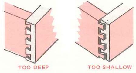
Although the factor of joint depth (see illustration) should give no problem, while testing on scrap also check this factor. Sometimes, the position in which you hold the router can affect the amount by which the bushing allows the bit to enter into the template openings.
After completing all the above, hold your router firmly down on the fixture template and make the cut, left-to-right, allowing the bushing to snugly follow the template outline. At the finish, pull the bit straight out away from the template; never lift it up through the template teeth, which would allow the (wider) cutting edge to contact and destroy the template. Examine your cut. If the bushing hasn't followed the template exactly the cut will be imperfect . in which case it can be perfected by repeating the cutting operation more carefully.
This completes the dovetail joint for the drawer left-front corner. To cut the right-front corner repeat the foregoing — but this time substitute the drawer right -side piece (with its top edge at the right side), turn the opposite end of the top piece to the front, and position both pieces (inner sides outward, as before) snugly against their stops at the right side of the fixture.
Laminated Plastics Edging

Laminated plastics, phenolics and laminates having similar bonding agents are much too hard to be shaped successfully with ordinary tools. For fast, clean edging — without danger of chipping — a carbidetipped bit ( refer to pp. 4 and 5 ) should be used...and the bit must be precisely guided in firm contact with the edge.
Professional quality trimming can be accomplished in two ways: 1) By using the Laminate Trimmer Accessory ( page 6 ) and the Formica Trimmer that is supplied with it. 2) By using either the Straight or the 22° Piloted Formica Trimmer ( page 4 ).
The laminated plastic trimmer (and its bit) offers the most versatility. First, the combination one-flute bit will trim either at a 20° bevel angle (if beveled bit end is used for cutting), or a straight, flush edge (if bit is lowered to use the straight portion). Second, the cutter attachment can be
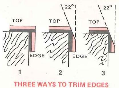
micro adjusted in or out to set the depth of cut as desired . which means that, if it is advisable, you can do the trimming in two (or more) passes at staged depth-of-cut settings, instead of trimming off a sizeable overhang all in one pass.
If you wish to do both flush and bevel trimming with the piloted type bit you will need both the flush and the 22° bevel bits. However, these bits do have two flutes (cut faster and smoother) — and the ball-bearing pilot is the best possible type of guide for following along any shape of edge contour.
With either of the above trimming methods the best practice is to pre-cut the laminating material so that it will overhang the wood to which it is bonded by about 1/8-in. on every side. After the bonding agent has set, use the router bit to trim off this 1/8-in. to make a flush or bevel-faced edge.
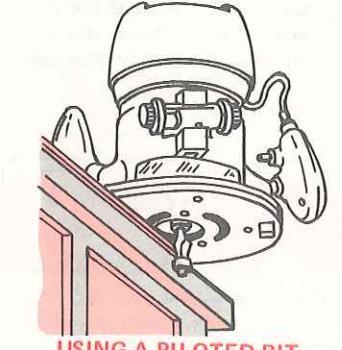
SING A PILOTED BIT


One of the most important, standard professional uses of a router is the fitting of door hinges to the door and frame. Hinges must be flush mounted in the wood, which requires accurately-shaped mortises to proper depth that are painstaking to do with a hand chisel . but can be done quickly and easily with a router and the right accessory.
Two different Craftsman accessories are available (see p. 6): 1) Individual hinge templates, furnished as a set of two for 3-1/2- and 4-in. long butt hinges, which must be positioned and nailed in place for each hinge mortising job (on door or on jamb). 2) An adjustable template assembly that can be set up for any door 3/4- to 2-1/2-in. thick, up to 7-ft. high, with two or three hinges from 1-3/4- to 5-in. long and, after the one set-up is made, can be
used for quick, easy mortising of any number of like doors and the door jambs.
A 1/2-in. straight router bit (1-3/4-in. or longer) together with the 5/8-in. guide bushing (see pp. 4-5) are also required.

With the three-template adjustable assembly the initial set-up is made by mounting the assembly on the door (hinge side) edge and adjusting it, as illustrated above. First, the two templates at the top and bottom ends are correctly positioned for these hinges, then the third template (if there will be three hinges) is centered between the first two. Next, each template is adjusted for hinge size. Afterwards, the router is adjusted for depth-of-cut, and the mortises are routed.
Without altering any adjustment the assembly can then be moved to the door jamb — or to another like door or jamb for routing of these mortises also.
When an individual template is used it must be nailed in place on the door and, later, on the jamb for routing of each hinge mortises.

TRIMMER ATTACHMENT
Shaper Table Routing

ROUTER/SABRE-SAW DELUXE TABLE
One of the table accessories will convert your router into a high-speed, bench-type wood shaper with which many projects can more easily be done than by holding and guiding the router. For one thing, there are many workpieces that it is more convenient to groove or edge shape on a table top, rather than setting up for hand routing. Then, again, the quick, easy workpiece positioning for a cut (or spaced cuts) by adjusting the table fence (or, with the deluxe model, by using the miter gauge) adds another advantage in many cases. Following are a few of the operations for which a table is especially helpful:
1. Jointing, or any similar edge shaping for which the bit must remove wood from the entire thickness of the workpiece edge. This cannot be done using a pilot as the guide; a pattern or other auxiliary guide is required when hand routing.
2. Routing through a workpiece to create a slot or latticework design.
3. Carving clear plastic by looking through it to a design on the underside.
4. Cutting narrowly spaced grooves, especially when these are to be started and/or stopped short of the workpiece edge — or, are to be angled to the edges.
In table shaping the bit is used upsidedown. If a pilot is used, it is at top. Bit rotation is, as illustrated, counterclockwise when viewed from above the workpiece. To obtain the same edge pattern produced by hand routing with the router on the workpiece top, the workpiece must be placed on the table bottom-side up .

Full-edge shaping (removal of the entire thickness of a workpiece edge) cannot be done using a pilot as the guide — the table fence must be used, and the workpiece edge must be straight (a curved or contoured edge cannot be guided against the fence). Most full-edge shaping is done with the rabbetting bit to straighten and plane the edge for making a tight butt joint (and is called "jointing"). Other bits can be used for full-edge shaping if you wish to simultaneously shape the edge and to recess it back to a finished dimension line.
Part-edge shaping (which leaves an uncut part at the top of the edge thick enough to firmly contact a guide) can be done against the fence (if the edge is straight), or can be (and, generally, is) done using a pilot to guide the edge against. When a pilot is used, the fence must be removed from the table. Do not leave the fence on the table even though it might appear that it won't interfere with your operation.
Grooving (which is done on the underside of the workpiece) can be done using the fence as a guide — if the groove is to be
and Edging Operations
straight and the fence can be positioned far enough back to place the groove as desired. Generally, however, the fence must be removed. With the fence removed, the miter gauge (if your model table has one) is used to guide the workpiece. Any straightedge board, clamped to the table top at the correct distance from the bit (to slide the workpiece edge along) can also be used.
Carving (also done on the underside of the workpiece) is done entirely by freehand guiding of the workpiece over the bit. Unless the workpiece is transparent (so you can see the bit through it), there is no sure, practical method of guiding.
IMPORTANT: Whenever freehand guiding or using the miter gauge or a straightedge guide, remove the fence from the table. Pilots can not be used for grooving or carving operations. Guide bushings are never used for table routing operations. A pattern (with a pilot) can be used only for outside or inside edge shaping, never for grooving or carving.
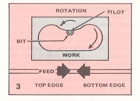
When edge shaping, the workpiece must always be fed to the bit against the bit rotation, to prevent the bit from hogging the work and pulling it out of your hands. Therefore, whenever the workpiece edge being shaped is between you and the bit (figs. 1 and 2 of the illustration), feed from right to left ... but if the bit is between you and the edge being shaped (fig. 3), feed from left to right .
Preferably, use the fence (fig. 1) for straight-edge shaping (although a pilot can be used, if desirable). A pilot (fig. 2) must be used for all outside curved or contoured edge shaping, and (fig. 3) for all inside edge shaping.
When grooving (or carving) the feed can be from either direction (fig. 4) — and the miter gauge (if used) can be at either side of the workpiece (it is always positioned behind, to push the workpiece).


turning experience is required, the Router Crafter makes it easy to produce a greater variety of spindle turning and carving designs than are possible with a wood lathe designed for homeshop use. A lathe is limited to cuts made while the workpiece is rotating, and careful shaping of these cuts requires operator expertise in the handling of the wood-turning chisels used to make them. A high-speed router is able to make clean cuts in a stationary workpiece, or in one rotated in any manner desired (all or part-way around, in either direction and at any convenient speed), and the cut shape is mechanically determined by the shape of bit and preset depth-of-cut selected by the operator.
The Router Crafter takes advantage of the router's versatility by providing a means of mounting a workpiece and guiding the router for a number of precise shaping operations. It will handle square or round workpieces 1- to 3-in. thick with a work area up to 36-in. long.
HOW ROUTER CRAFTER WORKS
The workpiece is mounted between two centers. One, in the "headstock", can be revolved by a hand crank to rotate the workpiece as desired — or, you can use the built-in indexing feature to lock the workpiece so that 1, 2, 3, 4, 6, 8, 12 or 24 evenly-spaced arcs of its circumference are positioned for shaping. The other center, in the adjustable "tailstock" can be posi-
tioned to accommodate various length workpieces and can also be adjusted to place this workpiece end on-center or off-center with respect to the headstock end (for straight- or tapered-spindle shaping).
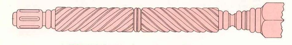
Your router is mounted on a carriage that can be pivoted up to lift the bit from the workpiece or lowered to an adjustable down position which, in combination with the router's adjustment feature, will determine the depth of cut to be made. This carriage is free to travel on a rail parallel to the workpiece centerline, and can be moved freely by hand to right or left for shaping any desired lengthwise portion of the workpiece. Adjustable stops on the rail can be set to hold the carriage stationary or to exactly limit its travel as desired. The carriage also can be secured to a cable which will pull the carriage along the rail as the headstock is rotated. Cable movement of the carriage is in fixed, uniform relation to the headstock rotation so that precisely pitched spirals can be cut simply by rotating the workpiece with the hand crank. Moreover, use of the previously mentioned indexing feature allows you to cut 2 to 24 different spirals evenly spaced around the workpiece (for roping effects) ... and spirals can be left-hand (advancing from bottom to top) or right-hand (from top to bottom), or a combination of both (to produce a diamond or "pineapple" effect).
- CUTTING PROCEDURES
There are four different procedures for making a cut.
1. Around the Workpiece and Continuing
to the Right. This procedure is used for rounding a square, reducing the diameter of a rounded section, and for all contour shaping. The carriage must be detached from the cable and the two carriage clamps must be positioned (and tightened) so as to stop carriage travel when the bit reaches the (respective) desired horizontal ends of the cut. The hand crank is used to revolve the workpiece, and the index pin must be disengaged so the cable won't be moved. The bit should be centered.

Always start at the left end of the area to be cut and work toward the right. After completing the depth-of-cut adjustment for the cut (or the first pass), lift the front of the carriage until the bit is above the workpiece - then turn the router on. Without turning the hand crank, carefully lower the carriage onto its feed-down screw(s). Turn the hand crank counterclockwise to over-complete one revolution. then continue to turn it while slowly moving the carriage to the right. Carriage movement must be such that the resulting spiral cuts overlap by at least one-quarter and crank movement should be at a steady pace, just fast enough for the bit to cut smoothly. At the end of the cut, lift the carriage up before turning the router off.
2. Around the Workpiece. This procedure is used for making beads, coves and reduced diameter flats (shoulders). The carriage must be detached from the cable and the two carriage clamps must be positioned (and tightened) to hold the carriage stationary at the location for the cut. The hand crank is used to revolve the work-
piece, and the index pin must be dis engaged so the cable won't be moved. The bit should be centered.
After completing the depth-of-cut adjustment for the cut (or the first pass), lift the front of the carriage until the bit is above the workpiece, then turn the router on. Without turning the hand crank, carefully lower the carriage onto its feed-down screw(s). Turn the hand crank counterclockwise to over-complete one revolution, then lift the carriage up and turn the router off. Hand crank movement should be at a steady pace, just fast enough for the bit to cut smoothly.
3. Lengthwise of the Workpiece. This is the procedure used for making reeds and flutes. The carriage must be detached from the cable and the two carriage clamps must be positioned (and tightened) so as to stop carriage travel when the bit reaches the (respective) desired horizontal ends of the cut. The hand crank is not used, and should be removed after using it to rotate the workpiece into position for the cut. The index pin must be engaged and the drum clamp must be tightened. The bit must be centered (unless purposely offcentered to produce a different cut shape).
Start at the left end of the cut to be made and work toward the right end. Begin with the drum locked in position as told in your Owner's Manual - and with the index pin engaged at the headstock number selected for this particular lengthwise cut. After completing the depth-of-cut adjustment for the cut (or the first pass), lift the front of the carriage until the bit is above the workpiece, then turn the router on. Make certain the carriage is against the left-hand carriage clamp, then carefully lower it onto its feed-down screw(s). Move the carriage by hand toward the other end at a steady pace, just fast enough for the bit to cut smoothly. At the end of the cut lift the carriage up, then turn the router
4. Around the Workpiece and Propor-
The Router Craftèr (con't.)

tionately Advancing (to the Right). This is the procedure used for cutting ropes and spirals. Advancement is always at the fixed ratio of one complete spiral per 6-3/4-in. of workpiece length, and is controlled by cable movement (as it winds or unwinds on the drum). The carriage must be attached to the cable, and the two carriage clamps must be positioned (and tightened) so as to stop carriage travel when the bit reaches the (respective) desired horizontal end(s) of the cut. The hand crank is used both to revolve the workpiece and (through cable movement) to travel the carriage. Therefore, the drum clamp must be loosened and the index pin must be engaged. The bit must be centered (unless purposely offcentered to produce a different cut shape).
For a left-hand rope or spiral cut ( illus-trated ), attach the carriage clamp to the upper cable lug and start at the left end of the desired cut. For a right-hand rope or spiral attach the carriage clamp to the lower cable lug and also start at the left end of the desired cut. This requires revolving the handcrank counterclockwise for a left-hand spiral — or, clockwise for a right-hand spiral.
After completing the depth-of-cut adjustment for the cut (or the first pass), lift the front of the carriage until the bit is above the workpiece, then turn the router on. Make certain the carriage is against the starting-position carriage clamp, then carefully lower it onto its feed-down screw(s). Next, turn the hand crank at a steady pace, just fast enough for the bit to cut smoothly. Continue to the end of the cut, then lift the carriage up and turn the router off.
WORKPIECE PREPARATION
As previously told, the workpiece must be
square, at least at the headstock end. It may be unnecessarily expensive to obtain a large enough piece (especially, if a rare wood is to be used) to make a square of the desired size. In such case, smaller pieces can be sandwiched together to form the desired square, as shown — or, even, can be assembled in any fashion that will produce the desired square. It is necessary, only, that adjoining faces be accurately planed and/or sanded to fit together smoothly enough for the joints to be unobjectionable. A good wood glue and tight clamping are required.

TWO WAYS OF ASSEMBLING A WORKPIECE
If the workpiece is to make a lamp (or, something else requiring an end-to-end center hole), the center-hole problem is easily solved by leaving a center opening when assembling the pieces to form the square. However, because the tailstock end must be center drilled and held by the tailstock center, this (one, only) end must then be capped (to provide a solid, drillable end). The cap needn't be a permanent part; it can be temporarily nailed or glued in place — but it should be 1/4-in. or more thick.

If a finished workpiece is to have considerably different diameters (or square sections) at different areas (like a lamp pedestal that is bigger at bottom), it isn't necessary to waste wood building up the maximum dimension throughout. You can build-up the dimension needed only at each area in which needed, as indicated by the illustration.
Another method of preparing a spindle is called "post-blocking", and calls for gluing pieces together, as illustrated, to form the beginning square. This method is particularly desirable when two or more woods of different characteristics are to be combined to provide the appearance of an inlaid workpiece. As illustrated, different wood pieces can be assembled so that, after finishing, they will result in a spindle having different wood characteristics in different areas.

Wood turnings also can be produced in sections, to be assembled later (with centered dowels) to make up the full length
- A Point-Cutting 1/4-Rd.
- B Core-Box B
- C Straight Bit
- D Point-Cutting Ogee
- E Veining Bit
- F Double-End V-Groove
- G V-Groove Chamfering Bit
- H Rabbet and Surface Bit
desired.
HE BITS TO USE
Any end-cutting bit can be used. This includes all of the shafted bits (pp. 4-5) and the rabbeting/surfacing bit (which is used without a pilot). None of the side-cutting bits (which includes all the other arbor-held bits) can be used; and the rabbeting/surfacing bit cannot be used with a pilot.
Particularly recommended, because of the desirable shapes they produce, are the 9/32-in. point-cutting ogee bit, the 1/2-in. core-box bit, and the 15/16-in. rabbeting/ surfacing bit (which bits are sold as a set together with the arbor and pilots for the rabbet bit). These and other very useful bits are shown in the accompanying illustration.
PLANNING A WORKPIECE
When planning the workpiece length, allowances must be made as shown by the Hlustration on next page. With the tailstock center screw extended approximately 3-3/4-in. (enough to allow shaping all the way from the tailstock end — dimension "A" in the illustration), the maximum allowable length for a 1-in. square workpiece is approximately 36-in. About 2-1/2-in. of this (dimension "B") will be inside of the headstock. If the workpiece is 3-in. square, its maximum length is only about 34-1/2-in., of which approximately 1-in. will be inside the headstock. In short, the maximum length of workpiece between

RECOMMENDED ROUTER BITS AND THE CUTS THESE MAKE


DIMENSIONS TO BE CONSIDERED WHEN PLANNING
the tailstock center and the outside of the headstock is approximately 33-1/2-in. (with tailstock center screw so extended).
Because the carriage will allow the bit to come only as close as 3-in. from the headstock, an added 3-in. must be reserved (from turning operations) at the headstock end. This means that a maximum length of approximately 30-1/2-in. (regardless of workpiece square size) can be reduced to a round, contour shaped, banded or lengthwise cut. And there are further limitations when using the cable to make spiral cuts. The closest to the headstock that either a left- or a right-hand spiral can end is 7-in. That is, maximum spiral-section length is approximately 26-1/2 inches, measured from the tailstock end.
Of course, if shaping must be done end-toend of a workpiece, you can do part of the shaping with one end in the headstock, then do the rest with the opposite end in the headstock (providing you leave, or can
nail or glue on, a square part to fit inside the headstock).
Having allowed for the above limitations, the next step is to plan the actual cuts. Draw, full size, as accurate a "picture" of the finished project as you can, keeping in mind the kinds of cuts that your various bits will make so that you can depict these with reasonable accuracy. All straight- or taper-rounded or contoured areas should be drawn exactly as you will want them to be. In addition, all banding cuts should be accurately drawn so that you can determine which bits to use and the depth-ofcut settings required.
Lengthwise cuts should be shown, as illustrated, with the number (around the workpiece) to be made. Remember: the spacing (in degrees) of lengthwise cuts is 360 (degrees) divided by the number of cuts and the size of bit used will determine the appearance (cut widths).
A WORKING PLAN – Shown Approx. 20% of Actual Size

SOME HELPFUL PLANNING FACTORS
When planning spiral cuts, keep in mind that each spiral, in one full revolution, will extend 6-3/4-in. If, as shown in the illustration, you plan to have six (indexed) spirals, the silhouettes (as shown along top of workpiece) of those six spirals will be spaced 1/6 of 6-3/4-in. apart (approx. 1-1/8-in.) For eight (indexed) spirals the spacing is 1/8 of 6-3/4 equals .84375 in.; for 12, 1/12 of 6-3/4 equals .5625 in., etc.
In short, to "picture" the roping or spiral cuts desired, mark off distances of 6-3/4-in. from the left side (start) of each spiraled section...then divide each distance into 6, 8, 12, etc. equal spaces according to the number of indexed spirals you plan to have. Each space will represent the top center of a spiral cut.
After making a reasonably comprehensive full-scale drawing of your project, the next step is to plan the sequence of cuts. If there are no tapered areas, your first cuts will be simply to reduce the square to required round (diameter) dimensions. To save time, mark your drawing to show the required minimum diameters ("Depth A", "Depth B" in the illustration) for various areas. When reducing the square to a
round, reduce it to these marked diameters — then proceed with the banding, lengthwise and roping cuts, as needed.
If there will be a taper-rounded area, draw it to scale and indicate the approximate tailstock setting (1/4-in., 1/2-in., etc.) you will use when setting up (as explained in your Owner's Manual).
If there will be a contoured area, draw it to scale — then project (as illustrated) the required template shape to achieve this contour.
If properly completed, your finished (fullscale) project drawing should not only show the final workpiece outline, it should also indicate to you each step of the turning operations together with the bits and depths-of-cut to be used — and how to set the tailstock (for any taper needed) and/or how to shape any template needed for a contoured area. Of course, to make such a drawing takes some time and calculations . it may be more fun and less tiring simply to start cutting and let chance determine the outcome (but you can't very well make duplicates — such as four matching table legs — in this manner).

WORKING PLAN THAT REQUIRES A TEMPLATE
CREATING TURNED SHAPES IS A FASCINATING PASTIME


 Loading...