

Sears | Craftsman 9-2926 The Circular Saw - An Illustrated Manual of Operation Instruction Guides
INDEX
Page GENERAL INFORMATION 2-3 Descriptive Data — Selection of Saw and Motor — Attachments and Accessories.
SET UP AND ADJUSTMENTS ....................................
PROPER OPERATING PROCEDURES ....................................
STANDARD SAWING OPERATIONS....................................
MAKING ANGLE CUTS 12 Bevel Cuts — Miter Cuts — Taper Ripping.
USES OF CUT-OFF BOARD AND PATTERNS 13 Handling Odd-Shaped Work — Cutting Straight Edges — Matching Edges of Offset Work.
SPECIAL SAWING OPERATIONS....................................
DADO AND GROOVER SAWS 18-20 The Tools — Adjustments — Work Handling — Regularly Spaced Grooves — Wide Grooves — Gains and Stopped Grooves — Tenons — Robbets — Rounding and Tapering Square Stock.
THE MOULDING HEAD AND CUTTERS 21-22 Set-Up — Patterns — Straight Edges — Strip Mouldings — Circular and Curved Work — Tenons and Raised Panels — Dowels — Ornamental Work — Spiral Turnings — Coves.
ABRASIVE WHEELS ...................................
30 DIFFERENT WOOD JOINTS 24-27 Completely illustrated instructions for making thirty different wood joints.
| RADIAL | SAWS . | |||
|---|---|---|---|---|
|
Design
Operat |
Features
ions and |
— Adjustments
Handling. |
- | Proper |
| SWING | SAWS |
| Design Features — Operations. | |
|---|---|
| CIRCULAR HAND SAWS | .30-31 |
| POWER HACK SAW | 31 |
| TABLES |


An Illustrated Manual of Operation
for the . HOME CRAFTSMAN SHOP OWNER
SET-UP — ADJUSTMENTS — PROPER HANDLING ALL STANDARD AND SPECIAL SAWING OPERATIONS. WOBBLE SAW — DADO HEAD — ABRASIVE WHEELS — 30 WOOD JOINTS — MOULDING OPERATIONS SHARPENING SAWS — TABLES
215 ILLUSTRATIONS
A CRAFTSMAN POWER TOOL HANDBOOK
Catalog No. 9-2926 PRINTED IN U. S. A.
Copyrighted 1954 SEARS, ROEBUCK and CO. REVISED 1954
For Sharpening Data Get "How To Sharpen" Booklet, Cat. No. 9–2924.
THE Circular Saw

8-INCH TILT ARBOR SAW
POWR-PANL
A safe, convenient way to hook up your saw, tool light and other accessories. Two plug-in outlets, power-line receptacle and an ON-OFF switch. Fits tool bench.
ADVANTAGES OF MODERN BENCH SAW
We would like to show you how, with your bench saw, you can produce the quality and variety of work which most people believe to be only possible for highly experienced cabinet makers and craftsmen. Take full advantage of your bench saw. It is a precision tool. Learn the many adjustments. Make good use of the different blades and accessories. There is practically no limit to the quality and variety of work you can then do.
Originally, the bench saw was simply a boxlike base inside of which there was a shaft (arbor or spindle) to hold the circular saw blade. The blade was mounted at one end of the arbor, and a power drive was connected to the other end. The top of the base was the worktable; and the saw blade projected up through a slot near the center of this worktable.
Modern saws are like this, but nearly all have several important added features. The saw blades can be raised or lowered through the table slot by a hand lever, and can be locked in any position. The table is fitted with an adjustable position rip fence and has one or two grooves for a sliding miter gage, both the fence and gage being used to guide work ac curately to the saw blade. Either the table (tilting table type) or the saw blade (tilting arbor type) can be tilted and locked at any angle up to 45 degrees. Also, nearly all modern bench saws use a V-belt drive; some having the motor in the base most with the motor outside. Most have a saw guard and a splitter. Antikickback pawls give added safety.
TOOL BENCHES
Solid, all-steel benches for
mounting saw and motor. Sizes
30x161/4 and 18x161/4 inches
— just the right height for
best work. Can be equipped
with casters.

SELECTION OF A SAW AND MOTOR
The named size of any circular saw is based on the diameter of the saw blade which it will swing. Sizes generally run from 6-inch up to 10-inch. With the blade as high as possible, a 7-inch saw will make a 2-inch cut; an 8inch will make a 2-1/2-inch cut; and a 10-inch will make a 3-1/4-inch cut, on an average. Motors should be at least 1/3, 1/2 and 3/4 h.p. minimum for the 7-, 8- and 10-inch saws, respectively, for home workshop use. Arbor rpms are given in the table on page 32.
It is a mistake to underpower a saw or to run it slower or faster than the manufacturer recommends, because saw blades are designed to operate at certain speeds.
AT PAN
TOOL LIGHT Adjustable position light always provides ample illumina-
tion for close, precise cutting. Fits on tool bench or table
Other than size, a choice must be made on the basis of refinements built into the better saws. The more precision adjustments there are for changing the height and angle of the blade in the table, and for positioning the fence and miter gage, the better the quality of work that can be done. Tilting arbor saws offer the greatest amount of safety and ease of operation when making bevel cuts; but tilting table saws are equally good for the straight cuts which represent 90 percent of all general sawing operations. Whether the saw base is a bench type, or a full height cabinet type, makes no difference in its efficiency; and table size is not too important as most better quality saws can be fitted with table extensions to increase table sizės.
These attachments provide for correct suspension mounting of

motors wherever necessary.
SAW BLADE STABILIZERS
A set of stabilizers, used as shown, makes flat ground and carbide tipped blades run truer — cut smoother.
TABLE EXTENSIONS
Available for many types of bench saws — to increase the work area for handling large workpieces.
bench saw set-up, adjustments and care
MOUNTING THE SAW
If not already built onto a cabinet, the bench saw can be mounted on a bench or any solid stand which will place the table top a few inches above your belt line. As freedom of movement around the saw is desirable, a moveable type stand that can be placed in the center of the workshop (for use) is preferable. Bolt the saw firmly to the stand; and provide an opening through the stand under the blade, so that sawdust can fall out.
A serviceable wooden stand like the one illustrated can easily be made. Typewriter or laundry tub stands can also be used with some
types of saws: and the rollers are handy for moving the saw about. It is advisable to make some arrangement for catching the sawdust. One way is to enclose the top part of the stand and place a container under the chute thus formed.


IMPORTANCE OF ACCURATE AD ILISTMENTS
Accurate work cannot be done on a saw that is not trued-up in every respect. On the other hand, even inexpensive saws can be made to produce excellent work, if properly adjusted Moreover the setting of the blade, table and fence in proper alignment is necessary for safety, to prevent possible binding of wood and kickbacks. (Wood can be thrown like an arrow by the whirling blade if it binds the blade.)
AD ILISTING SAW BLADE PARALLEL TO TABLE GROOVES
Set saw blade for deepest cut. Make a pencil mark on the tooth that is just above the table top at the front of the blade Measure distance from tooth point to the right-hand table groove. Rotate saw by hand to place this same tooth just above table top at the rear, then again measure distance from tooth to same groove. If the two measurements are not exactly equal, make them so. On a tilting table type, loosen screws that hold table top to base and shift the table top (the screw holes in top

are slotted so that it can be shifted). On a tilting arbor type, loosen the screws that secure each of the two table trunnions to the table and shift entire arbor assembly. Re-check measurements and securely tighten all screws.
ADJUSTING FENCE PARALLEL TO SAW BIADE
On saws which have a fence guide har and screw feed, align the fence parallel to the right hand table groove. To do this, loosen the bolts that secure the fence to the guide har slide

On saws without a precision fence guide bar and/or a non-adjustable table top, it is necessary to align fence with saw blade, each time the fence is used. To do this quickly keep on hand a suitable length of board with
perfectly parallel edges. Lay board on table pressed firmly against side of saw blade, and

set fence parallel to outer edge of board by measuring with a ruler at each end.
AD JUSTING THE SCALE

Using an accurate square, set the saw blade at right angles to the table top. Then adjust the pointer on the tilt scale to zero. Also, if saw has a stop screw which automatically stops it at zero; adjust this screw to the proper position.
AD ILISTING MITER GAGE SCALE
Using an accurate square, lock the miter gage at the square position. Make a trial cut on a fairly wide board, then check this cut with the

square. If cut is accurate, set the pointer on the miter gage to the 90-degree mark on the scale. When table edge is suitable, gage can be quickly set by turning it upside down and aligning it with table edge.
ADJUSTING FENCE SCALE

Run the fence over until it lightly touches the blade. then set the pointer to zero on the graduated guide bar.
AD JUSTING THE SPLITTER

The splitter serves to keep the saw cut (kerf) open to prevent binding of blade in the wood Obviously, the splitte: must be perfectly aligned with the cut made by the blade Thin cardboard washers can be used for aligning the splitter.
SAW MAINTENANCE
Keep your bench saw as clean and free from sawdust accumulations as possible. Wipe off the table top, blade and other exposed metal parts with an oily rag; dust other parts with a dry rag. Keep bearings lubricated as instructed by the manufacturer

proper operating procedure

DRESS PROPERLY
Floppy sleeves and loose ties are an invitation to danger, and are easily caught by whirling saw blade to pull operator into contact with the blade. Sleeves should be down with cuffs fastened; or wear short sleeves. Do not wear a tie or other loose article. A work apron is excellent. Also, if a quantity of work is to be done, some type of goggles or face shield to keep sawdust out of the eyes (especially if working in close quarters) will be helpful.
NEVER STOP BEING CAREFUL
One moment of inattention can cost you a painful injury. Most sawing operations are so simple, and so quickly and easily done, that some operators become careless and inattentive. Do not fall into this unsafe habit. Always be alert!
A LOW BLADE IS THE SAFEST
Equally good cuts can be made with the blade elevated to full height, or with it raised just enough to clear the top of the workpiece by approximately 1/4 inch. When the blade is in the second position, a little more power is required to drive the saw, because of the long

cutting angle of the blade. Also, a little more feed pressure may be needed. But this second position is the safer one, and any saw that is properly powered will operate, with little noticeable difference, in any blade position.

The lower position is safer because the blade enters the wood at an angle more nearly parallel with the direction of feed, and there is better opportunity to hold the work against kickback.
AVOID KICKBACKS
Anything that will cause the blade to bind in the work will cause a kickback. Under certain circumstances, the work can be thrown from the saw with extreme force endangering the operator. Most common causes of
the ork der the om rce

the workpiece out of line when freehand feeding. 2 Misalignment of fence and blade so that work is twisted or wedged between fence and blade during feeding. 5. Failure to use splitter (or to otherwise hold the kerf open) so that a long It is best to use the splitter. and if the splitter is fitted with antikickback pawls, so much the better. If for any reason splitter is not used. and you are making a long cut, stop and put a wedge into the cut as soon as possible to hold the kerf open.
Too rapid a feed, knots or sap in the workpiece, a dull or rusty blade can also be causes of kickback. Hold work extra firmly to table when starting a cut, passing

a knot or during special operations. Avoid using damp or warped lumber without special precautions (page 8).
Warped and crooked workpieces can also cause kickback, especially if placed on the table or

against fence in a manner that permits rocking or twisting during the feeding process. Always make certain that work will slide on table and along fence without tendency to bind the saw blade

KEEP HANDS CLEAR OF THE BLADE
Always be certain that there is ample room between the blade and the fence, before getting your hand into this position. To be on the safe side, make it a rule not to use your hand to push work through, unless the space available is equal to the maximum width of your
palm. For added safety, when using your hand for the push through, hook the two outer fingers over the fence to keep hand steady, and tuck the thumb in behind the palm and anchor it against the end of the workpiece.
If work is too narrow for hand to be sately used, use a push stick (page 9), or walk around the saw and pull the work through from behind to finish the cut. Hold work as you walk around the saw.
AVOID AWKWARD HAND POSITIONS
When crosscutting, use the miter gage, even for straight cuts. Freehand crosscutting involves more risk because kickbacks are especially likely to occur in this type of operation. If using the left-hand groove, stand at the left

side of blade. Place left hand on workpiece with thumb hooked behind gage at center of gage. Use this hand to hold work against gage, and to push gage and work to the saw. If right hand is used, keep it as close to center of gage as possible.
Never advance an unwieldy workpiece to the saw without first providing a good support to keep it from being upset. It takes but a few minutes to arrange some safe support that will allow work to slide on table without danger of being upset or kicked back..

NEVER BIND FREE END OF WORK BETWEEN BLADE AND A STOP

When using a miter gage extension (illustrated), the fence or a stop (p. 11), always arrange it so that the piece being cut off will be free to fall away from the blade. That is: Do all the holding on one side of the work only.
TWO OBVIOUS "DON'TS"
Don't reach up to saw blade to grab a piece of free wood—until blade has stopped. Don't let floor become littered so that your feet might slip. Sawdust is a definite fire hazard, especially after being damp, and should not be allowed to accumulate.
- Start
standard saw operations

RIP BLADE


HOLLOW-GROUND COMBINATION BLADE
NAIL-CUTTING BLADE
SELECTION OF SAW BLADES
For average home shop use there are three good all purpose blades: 1) The new, extra-safe tungsten carbide tipped, 8-tooth blade (which seldom needs sharpening if properly used); 2) The fancy-tooth combination; and 3) The hollowground planer blade. All will rip, crosscut and miter equally well. The carbide tips of (1) are diamond ground for smooth fast cutting - cut their own clearances (being slightly larger than the blade). The other two bave an identical tooth pattern; but the short, flat-ground cutting teeth of the fancy-tooth blade are set alternately right and left (for cutting clearance)-and the hollow-ground blade obtains clearance by being tapered from the center out (and is more expensive).
Two special purpose blades are the rip and the crosscut. These are generally used in production work because of the greater speeds obtainable by each at its own special job. Another popular special purpose blade is the one designed for nail cutting. It is very useful when sawing up old used lumber containing nails that would ruin the other blades. There are also many other specialized blades for different lumbers, other materials, and special types of cuts.
STANDARD TOOTH PATTERNS
The tooth patterns, names and distinctive features of the three standard saw types are shown in the illustration. Each tooth should conform as nearly as possible to the pattern of the blade, if a blade is to cut smooth and fast. For this reason, it is good practice to make a paper pattern of each new blade so that, when sharpening becomes necessary, you can refer back to the original pattern for proper reshaping of the teeth. .Note on the pattern the degree of tooth set, filing angles, and other useful information.
RIPPING
Ripping is the sawing of wood with the grain. It is generally done with the help of the fence as a guide to position and maintain the work at the correct width for the cut. Because the work is pushed along the fence, it must have a reasonably straight edge to make sliding contact with the fence. Also, work must make solid contact with the table, so that it will not wobble during the operation. Provide a straight edge to go against the fence, even if this means temporary nailing of an auxiliary straight edge board to the work to serve as a guide. If a moulding fence (with cut-out near center) is used, clamp an auxiliary guide board to the fence. If workpiece is warped, turn the hollow side down
Use of the saw guard is recommended; but the splitter should always be used in ripping op-

erations. Wood cut with the grain tends to spring closed behind the saw and bind the saw blade. If, for any reason, splitter is not used, stop and insert a wedge in the kerf just as soon as cut is long enough to do so.
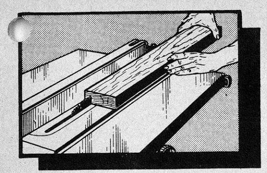
Set fence to desired width of cut, either by using the scale on the fence guide bar, or by measuring distance between blade and fence. Fence is almost always used on right-hand side of blade. Stand a little to the right of center to avoid being sprayed with sawdust and to be clear of work in case of a kickback. Start saw and advance work to the blade, using left hand to hold it down against tendency to kickback, and right hand to push it into blade. As cut nears completion, move left hand to safe distance from blade, and
push work through with right hand alone. Weight of cut portion of board will generally hold it down on table; but if work is so light that blade will tend to kick it up, clamp a hold-down in place before starting the
cut, or stop and place a weight on end of board to keep workpiece down on table. (If splitter has antikickback pawls, this is not necessary.) Never reach in back of the blade with either hand to hold work down.
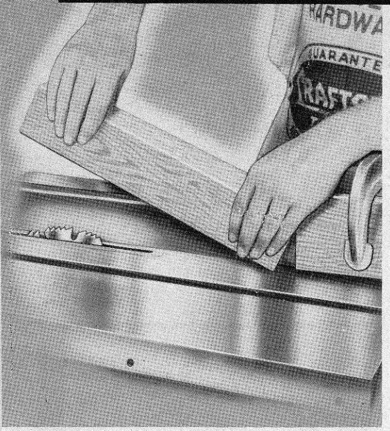
Best practice when pushing end of work past blade with right hand is to lock one or two fingers over fence to anchor hand, and tuck thumb behind end of board to push it. (See illustration at top of page.) Skilled operators generally walk around saw and pull end of work through, whenever workpiece is long enough. Never backtrack by pulling work from
behind blade toward the front. To lift partially completed work from table, stop the saw. Finished work that has cleared the blade can be lifted off table from in back of blade.

HANDLING NARROW WORK
When there is less than the width of your palm between fence and blade, do not attempt to push work through by hand. Use a push stick like that shown in illustration, or pull work through from behind saw.
HANDLING LONG WORK
Do not leave a long board unsupported so that the spring of the board causes it to shift on table when sawing. Use some sort of support to catch end of board behind blade; and, if board is very long, use another support in front of saw (in which case board can be pulled through after you have advanced up to the front support). Suitable table extension can usually be purchased. A good homemade support is illustrated. Ordinary wooden horses of proper height will also do; and the drill press table makes an excellent adjustable height support.

-8-
standard saw operations (cont'd)

RESAWING
Resawing is the cutting of thick boards into thinner ones. It is a ripping operation. Small boards can be resawed in one pass; but larger ones require two passes, one pass along each edge of the board. Boards up to 43/4 inches wide can be completely resawed on an 8-inch saw; the 10-inch saw will handle boards up to 61/4 inches wide.
When two cuts from opposite edges are required, these should be made to overlap about V2 inch at the approximate center of the board. If the first cut is too deep, the kerf will close and bind the saw on the second cut, with danger of kickback. Also, when the kerf closes, the two sides of the cut are no longer parallel to the saw blade, and the saw will cut into them to spoil their appearance.
Position the fence and make the first cut. Then turn the board end for end (so that the same face is still against the fence), to make the second cut. Hold board securely against kickback, and finish each cut by using a push stick, or by pulling work through from back side of saw.
If the board is too wide, make two maximum cuts from the opposite edges, then finish resawing the board on a bandsaw (the blade of which will track nicely in the cuts already made).


CROSSCUTTING
Crosscutting is the sawing of wood across the grain. As planks are cut with the grain the long way, the long edge of the work is placed across the table top when crosscutting. Therefore, the miter gage is used to guide the work to the saw, and the work is held in position by keeping it firmly in contact with the gage. Most operators prefer to use the left-hand table groove. In this case, the left hand is used to hold the work in contact with the gage and to push the work and gage into the saw blade. The right hand is free to assist in the feeding operation, as required. If the right hand groove
Ordinarily, the gage is placed in the table groove with the slide in front. When the work is so wide that it completely covers table in front of saw, reverse the gage. However, make certain that your gage will not strike the blade — on some saws the right-hand table groove is too close to permit reversing the gage.
Square crosscutting is done with the miter gage set at zero (at a right angle to the slide and groove). The splitter need not be removed, but is not needed for this operation. (It is best never to remove splitter unless necessary.) Start the cut slowly and hold work firmly to table to prevent kickback or chatter. (Loosely held workpiece will sometimes vibrate against table when crosscutting. This tends to bind the blade and dull the teeth.)


USE OF MITER GAGE AUXILIARY AND TABLE EXTENSION
An auxiliary extension, screwed or bolted to the miter gage, greatly improves the use of the gage as a support. Such an extension is very much needed to keep long work from twisting on the saw blade. If fitted with pin points (phonograph needles are excellent) or sandpaper to hold the
work, the extension will also be a big help in preventing side creep of the work. When much long work is to be
handled, a table extension will be very useful. Crosscutting long boards always creates a problem of support, and a wider table is obviously better. If board overhangs table enough to sag at either end, it will be necessary to support the sagging end by sliding it along a wooden horse or auxiliary table placed at the side of the saw.
USE OF STOPS AND CLEARANCE BLOCKS Crosscut-Trimming of Duplicate Parts
To produce a number of identical pieces by crosscutting various lengths of scrap from var-
ious length workpieces, a stop fastened to the miter gage is used. When the pieces are short enough, the handiest stop to use is the stop rod with which many miter gages are equipped. This


rod can be set to position each workpiece exactly the same.
If the workpieces are too long, or if there is no stop rod on the gage, it is better to use a miter gage extension. A wood block can be screwed or clamped to the extension to serve as a stop. Each workpiece is bolted against the stop to position it for cutting.
Crosscutting Duplicate Pieces from Original Piece
When it is desired to establish the length of the piece being cut-off (instead of the piece remaining), the fence and clearance block can be used for a stop. Never use a stop on the miter gage or miter gage extension to hold the piece being cut-off, as this would bind the piece to the blade and result in a kickback.
The clearance block is a metal or wood yoke that can be fitted over the fence like a collar. The block is positioned on the fence so that it can be used to locate the work against the miter gage, before the sawing operation begins. This block must not make contact with the work when work is pushed forward into the saw. If the setting of the fence gage is noted, the block and fence set up can be duplicated at any later date.
A stop that will serve the same purpose as the clearance block can be formed by clamping a piece of wood to the front corner of the table on the side opposite the miter gage. The miter gage clamp illustrated is excellent for holding work accurately in the position established by the stop. (Refer to page 12.)

making angle cuts

BEVEL CUTS
Bevels from 1 degree to 45 degrees are cut by tilting the saw blade or the table, depending upon type of saw. Operations on the tilting blade saw are much the same as standard ripping and crosscutting operations, as the table remains level With a tilting table saw, however some extra precaution must be taken to prevent work from sliding down the table slope as it is fed to the saw. When the fence is used (for bevel ripping), it will serve this purpose. In crosscut beveling, when the miter gage is used, a miter gage extension (refer to page 11). with anchor points or sandpaper on the contact face should be used to hold work firmly. A miter gage clamp also serves very well to hold work in position.
The fence and miter gage should always be placed on the low side of the blade, when using a tilting table saw. It is much safer and easier to work on the low side.
MITER CUTS
Miters are crosscuts at an angle to the edge of the workpiece. The miter gage is set at the required angle to make the cut.
Unless the work is very tightly held, it will creep while making a miter cut. This creep is into the saw blade, and is equal to the set of the teeth, or the taper of a hollow-ground blade. To eliminate creep, use a miter gage extension (refer to page 11) with anchor points. If great accuracy is desired, use a miter gage clamp.


Ripped tapers are cut with an adjustable µg like the one illustrated. First, however, the amount of taper per foot must be determined. This is easily figured, as shown in the illustration. If the taper is to be all on one side, instead of on two opposite sides, multiply by 12 instead of 6 when using the formula.
After determining correct taper per foot, open the jig until the distance between the two jig arms at the 12-inch mark is the same as the taper desired. Lock the jig. It is now ready to cut the first taper; or, if a square leg is being worked, it is properly set to cut any two (only) adjacent sides. Position the fence so that inner edge of saw blade just touches corner of work, then slide the jig and work together past the blade to make the cut. If a square piece is being tapered, cut one adjacent side in the same manner. Before cutting the remaining side or sides, open the jig to twice the previous setting to allow for the tapers already cut.

cut-off board and patterns
HANDLING ODD-SHAPED WORK
It is often necessary to make a straight cut on an odd-shaped board that cannot be guided by the fence or miter gage. A cut-off board is very useful for jobs of this kind. The board is easily made, as shown in the illustration above. The guide strip on bottom of board should be a good sliding fit in the table grooves; and matching V-grooves in the faces
of the boards are useful for holding dowels and similar round stock. If the top board is also countersunk to receive the bolt heads, the fixture can be turned upside down (by reversing bolts) for freehand use.

CUTTING TRUE STRAIGHT EDGES
When reversed, as noted above, the cut-off board can be used for freehand operations.
One such use is for trimming veneer for jointing. Lock both pieces of veneer together in the cut-off board with approximately 1/2 inch of the ragged edge of each exposed at one side. Clamp an auxiliary guide, one inch or more thick, to the fence. Position this guide high enough above table to ride over the top of the saw blade when blade is projected just high enough to cut through the work in the cut-off board. Position fence so as to trim approximately 1/4 inch off of the workpieces, then slide the cut-off board along the auxiliary guide to make the cut.
A board with two ragged edges can be similarly trimmed and trued to have two parallel straight edges. If more than 3/4 inch must be trimmed from edge of board, use a thicker

auxiliary guide like the one shown.
Odd-shaped, straight-sided pieces can be cut with the aid of a pattern and an auxiliary fence guide. The pattern can be any desired shape, but should be thick enough to make firm con-

tact with the guide. A guide like the one illustrated is best because it is wide enough to provide ample clearance out from the fence. The guide must have a small rabbet at bottom of lower edge to provide clearance for the saw blade, and must be positioned flush with outer face of blade.
If a wooden pattern is used, nail it lightly to the workpiece. The cut-off board can also be used to hold workpiece and
useful when pattern is of a material that cannot be nailed to the workpiece. Make the set up as shown in the illustration, leaving room under the guide for the edge of the work. Slide

pattern along guide to make each cut required.
MATCHING EDGES OF OFFSET WORK
If it is desired to have a second piece of work (bottom piece) larger than the pattern (top piece), use the pattern sawing set up already described; but set the guide out over the blade by the amount of offset desired between each edge of second piece and pattern.
special saw operations
MAKING CENTER CUTS
If a long slot through the center of a board is to be cut, it is necessary to drop the board down on top of the saw blade to start the cut.
Always clamp some type of a stop to the table in front of the blade to hold the front end of board against kickback. Stand at one side or in back of the saw. Place front of board on table against the stop, then lower back of board slowly down over the blade until blade cuts through and board is flat on table. Push or pull board until blade is at end of desired cut, then stop the saw before lifting board from table.
Make a second cut, parallel to the first, in like manner. The stop and fence can be positioned to locate the two cuts. Center section of board can be cut free with a scroll saw or chisel.
MAKING EDGE CUTS
(Design for a Hold-in)
Edge cutting, like resawing, requires careful support of the workpiece. This is especially true of high, thin boards. Always secure an auxiliary guide to the fence to give it sufficient height to support at least the bottom two-thirds of the work. Also, preferably, always use a hold-in. This can be a spring metal guide (many types can be purchased), or a homemade wood spring.
The wood spring is simply a length of wood, miter cut (at approximately a 45-degree angle)

and slotted at one end. It is clamped to the table so that the mitered end bears against the work to keep it against the fence. Position the hold-in to contact the work just behind the front edge of the blade. If work is not high enough for a good grip, always finish cut with a push stick or by pulling it through.
MAKING END CUTS
End cuts are more difficult than edge cuts because the small portion of board at bottom does not give a firm sliding contact with the table. Special end cuts, like tenons, are generally made with a jig (page 17); but such cuts can be made as illustrated. Note that the auxiliary guide fastened to the fence is high enough for operator to hook fingers over the top to support right hand. Also note that push stick is used and left hand is kept very much in the clear, away from the blade.

CUTTING A RABBET
A rabbet is cut by making two saw cuts at right angles to each other, to remove a corner from the workpiece edge.
First mark the size of the rabbet on one end of the work as a guide for setting the required saw blade projections. Set the blade so that the top of the teeth just touch the center of the
mark for the cut; then make the cut into the flat side of the board first. Use either the fence or the miter gage for guide, as required. Then reset the saw in similar manner, and make the second cut. This second cut will be either an edge cut or an end cut, and the workpiece should be guided accordingly.

CUTTING CURVES

Though intended for straight line work only, the bench saw can be used to cut slow curves. The maximum curvature should not exceed 1/2 inch per foot. One pattern for a concave (inside) curve, and another for a convex (out-

side) curve is needed. These patterns are made to the degree of curvature desired. The con-
cave pattern must be at least as long as the workpiece. A convex pattern can be any length that will give good contact — and it can only be used when workpiece already has one edge cut to a concave curve that will match the pattern (a straight edge could not be guided by the pattern as there would be only one point of contact.)
Set the blade to barely project through the work. Clamp the concave pattern to the fence with the center of the curve exactly in line with the blade axis (center of blade). Rig a metal or wood spring hold-in to keep work in contact with the pattern. Feed work slowly. If the convex pattern is to be used for shaping the other edge of the work, the set up and procedure are the same.
CUTTING COVES
Coves are rounded grooves made by feeding the work at an angle to the saw blade, taking light cuts of about 1/8 inch at a time until full depth is reached. Cove cuts have many uses in shaping edges, the most popular being the making of rounded table corners.

To cut a cove first draw a pencil outline of the desired cove on one end of your workpiece. Now draw a horizontal line touching the top (highest part) of the cove outline — and draw a vertical line through the center of the cove outline. These lines will help guide the cut.

special saw operations (cont'd)
Using two straightedge boards, make a frame (by nailing these together with cross pieces) which will: 1) Be exactly the same width inside as the width of the desired cove; and 2) Have perfectly straight, parallel inner edges.

Measure the height of the vertical line which marks the center of your cove outline (above) Place the frame over the saw blade and turn it until the sides of the blade just touch the inner sides of the two parallel straightedge boards. Rotate the blade by hand to make certain it will just touch the frame, without cutting into it. Now draw a pencil line on the table top, using the inner edge of the left-hand straightedge board as a guide. This line indicates the angle at which the workpiece must be fed to the saw blade to cut the desired cove. Draw a second line using the inner edge of the other straightedge as a guide. Remove the frame and draw a third line exactly halfway between the first two lines. This third line is the centerline of the saw blade

Measure the distance between the vertical line (on edge of workpiece) which marks the center of your cove outline and the outer workpiece edge which will be at your left when cutting the cove. Clamp a straightedge board (to serve as a guide) to the table top, with the straight edge parallel to the three pencil lines drawn on the table top — and have it exactly the same distance (A in illustration) from the centerline of the saw blade as the measurement you just made.
hade. Lower the saw blade until it projects up no more than 1/8 inch. Start the saw and feed your workpiece very slowly, sliding it over the blade while keeping the left edge firmly against the straightedge guide. After each full pass, raise the blade another 1/8 inch (no more), and repeat —until the full desired depth is reached.
The finished cove will not be perfectly round because the work is always fed at an angle to the blade. If it is fed at a 45° angle (the widest

angle you can use without strain on the saw blade) the cove will be most nearly round will become less and less round as the angle becomes narrower (as shown in accompanying illustration).

To make rounded table corners first make a split turning on your lathe, turning down the outer sides of the two halves to the desired exterior dimensions for the corners. Separate the two halves and work a cove in each piece — to make the inner sides of the corners. Now slice each piece in half — and you have four useable corners which can be mounted to the table top and sides with dowel pins, or by cutting rabbets (p. 19) to make glue joints.
CUTTING BOWLS

Bowl-like cuts can be made in much the same manner that coves are cut. However, the depth of any bowl cut will be in fixed proportion to the width, for any one size of saw blade. The smaller blades will make cuts more nearly semi-circular.
If a round workpiece is used, two boards clamped to the table to form a "V" will serve as a guide. Arrange these in back of the blade so that, when work is positioned against them, the top center of the blade will be at the center of the desired cut. If a square workpiece is used, rig up an arm to hold a pivot at center of workpiece. Take 1/8-inch cuts at a time, revolving work one complete turn for each cut until finished.
USING A MITER BOARD
The ordinary (square) miter for joining two boards is cut with the miter gage set at 45 degrees. To cut the opposite end of the same board, turn the board upside down If board cannot be turned upside down, move the miter gage to the opposite side of the saw and reset it to 45 degrees in the opposite direction. If work is allowed to creep (page 11) the resulting joints will be out of square (as in the illustration). For this reason cabinet joints are best made with the use of a miter
A simple miter board can be quickly made as illustrated. The two mitered stops should be cut at the same time, with the miter gage set at 45 degrees. Guide strips are ar-
ranged to slide in the miter gage grooves. Workpieces should be square cut to the desired overall length plus 1/4 inch to allow for saw kerfs, and are then miter cut in the jig.
THE TENONING JIG
Cutting tenons, like making other end cuts (page 14), requires special holding of the work. Two homemade tenoning jigs that will make it easy to hold and position the work are illustrated. Each is fitted with a stop shoulder that is cut away to allow passage of the saw blade when the jig is close enough to the blade to make the inside cheek cut of a tenon. Jigs designed to travel in the miter gage groove, and having adjustments for accurate positioning of the work, can be purchased.
CUTTING TENONS
When cutting tenons, make the shoulder cuts first, using a stop block to position these cuts accurately. Then make the two cheek cuts and the edge cut.
There are three methods of making the cheek cuts. The simplest method is to clamp the work to the tenoning jig and position the jig and fence so as to cut out the cheek on the side away from the jig. Then turn the work around and cut the other cheek, without moving the fence. This method centers the tenon accurately. but the widths of the tenons will vary if there are variations in the thickness of the wood.
Accurate width tenons can be cut by using a backing block (as illustrated). This block should be the width of the desired tenon plus the width of the saw kerf. If there are variations in the thickness of the wood, tenons cut in this manner will not all be accurately centered.
Accurately centered, exact width tenons can be cut by using two saw blades of the same diameter, with a collar between. Paper discs can be used with the metal collar to space the blades as required. The work is clamped to the jig, and the fence can be positioned, as needed, to accurately center each tenon that is cut.


dado and groover saws

HOW THE DADO SAW WORKS A Typical Dado Set
The dado saw or head, as it is also called, is a special set of blades for cutting grooves and dados on the circular saw. This head consists of two solid, full-circle outside blades and a number of two-toothed chipper blades for use between the outside blades.
A typical head set contains two ¼-inch thick outside blades, four ¼-inch thick chipper blades, and one 1/16-inch thick chipper. With this assortment you can cut grooves as follows: ¼s inch (1 outside blade); ¼ inch (2 outside blades); 5/16-inch (2 outside blades and the 1/16 chipper) — and additional widths increased 1/16 inch each, up to 13/16 inch maximum. The outside blades cut like a combination blade; the chippers act as planers to smooth out the area between the two outside blades — and cannot be used except between two outside blades or they will tear the work.
The Dado Head Set-Up

A dado insert must be used to replace the standard table insert. This can, if necessary be a piece of plywood cut to fit the table insert opening and provided with a wide slot for the dado head.
Dado blades are generally smaller in diameter than standard saw blades so that the depth-ofcut gage probably cannot be used. Each setting of the dado head must be made by aligning the top of the blades with a mark on the work. Settings should be checked on scrap lumber. As the splitter and guard cannot be used, these should be removed for dado operations.
Whenever two or more chippers are used, space the swaged ends of the chippers as evenly as possible around the circumference of the assembled head. Avoid having the teeth of two or more chippers in a straight line across the head. Each swaged chipper end must fall in a gullet of the ådjacent outer blade.
Fractional Thickness Adjustments
Fractional adjustments in the thickness of a dado head can be made by using paper washers to seperate the outside blades from the chippers. In this manner thickness variations up to 1/16 inch can be obtained. Such adjustments are often useful in securing a tight fit for a grooved joint.
HOW THE GROOVER SAW WORKS
A groover saw is a wide, 8-tooth blade with chisel-type teeth designed for cutting grooves. It will do the same work as a dado head but is not variable in thickness as each saw will cut only one size groove. Standard widths generally are: 1/8, 3/16, 1/4, 5/16, 3/8, 1/2, 5/8 and 3/4-inch; but other sizes can be obtained.
HANDLING WORKPIECES

Operations with the dado head are much the same as with a standard blade. It must be remembered, however, that the dado head takes a bigger bite in the workpiece; and that the likelihood of kickback is therefore increased. As the splitter, and
consequently the anti-kickback pawls, cannot be used, the workpiece should be held down firmly by hand, or by use of a hold-down jig like the one illustrated.
REGULARLY SPACED GROOVES
Regular spacing of grooves can be done by using the stop rod on the miter gage to engage the last groove cut, and so set the position for

the next groove. Another method is to use a notched stop block (below) to fix the starting positions of the various grooves. This block should be clamped to the table well ahead of the blades so that work is free from it before cutting operation begins. The block can be notched in regular steps, or according to any desired pattern. A third method is to clamp a yardstick to the miter gage (or miter gage extension), and position the work for any desired spacing of grooves by referring to the inch marks on the stick.
WIDE GROOVES
When a groove wider than the dado head is needed, it must be cut in two or more passes. Use a notched stop block to start each pass.
When moving the workpiece over to make additional cuts, move it just a little less than the thickness of the head so that the cuts will overlap. Also remember that right side of head will establish right edge of cut, and the left side of the head will establish left edge of cut.
CUTTING GAINS AND STOPPED GROOVES
A gain is a groove that is closed at one end; stopped grooves are closed at both ends. Both are used in making joints.
A gain is started like an ordinary groove or dado; but a stop block is used to fix the end of the cut. To


locate this block, place work alongside dado and position it so that back edge of dado lines up with the desired end of the groove. Butt the block up against back end of work, and clamp it to the table, or fence. Always stop saw before removing finished work.
To cut a stopped groove, both the end stop block and a starting block must be used. The starting block is located just like the end block, and is clamped to table or fence. Butt front of work against starting block, and lower work onto the blades.
DADO TENONS
Tenons are usually cut with the widest dado combination. If tenon is still wider than the dado head, make the inside
cut first and widen the tenon by making later cuts, advancing toward the end. The notched stop block already described can be used.

DADO RABBETS
Rabbets are quickly cut with the dado head, using the fence as a guide. Use a combination a little wider than the rabbet to insure a clean edge. Preferably make the cut on the edge

dado and groover saws (cont'd)
away from the fence; otherwise an auxiliary fence, cut out like a moulding fence, must be used.

ROUNDING AND TAPERING SQUARE
Perfect round and tapered-round cuts (such as round and tapered-round tenons) can be quickly cut on the bench saw. A fixture like the one illustrated, and a dado head, are all that are needed. The fixture is designed to be clamped to the saw table, and to hold round or square stock as in a lathe. One end of the fixture is adjustable horizontally, so that the fixture will hold different length workpieces, and is also adjustable vertically so that one end of the workpiece can be raised up for making taper cuts. The other end is swivel mounted on a horizontal axis so that it can turn whenever the adjustable end is raised up. The bed piece is cut out to fit over the dado head.
To use the fixture, first mount the workpiece in it as in a lathe, with the end (or middle area) that is to be rounded at the nonadjustable end of the fixture. Locate the fixture over the dado head with the center line of the workpiece exactly above and parallel with the axis of the dado head, and the area in which the first cut is to be made directly over the dado
head. Clamp fixture to table in this position Now start the saw and raise

dado head another 1/8 to 1/4 inch, and repeat the cutting process. Continue this until full desired depth of cut is reached. If a cut longer than the width of the dado head
is required, move the fixture over and repeat the
above process. The fence can be used to locate the fixture and help keep it square with the blades. When so used, it will also help to fix the amount of fixture movement needed to position additional cuts.
To cut tapered round tenons or sections, raise the adjustable end of the fixture to position the workpiece at the desired angle of taper with respect to the saw table. If tapered end is to be pointed, cut wood nearly through (as when using a lathe), then finish the cut with a -----------------------------------


20-

THE SET-UP
A dado insert with a 1-1/8-inch wide slot will accomodate the moulding cutter head. You can also make an insert from plywood — and, if close work with narrow knives is to be done, a specially made insert that will give support to the work right up to the knives will be helpful. The cutter head is installed in place of your regular blade — and need not be removed to install various cutters (instructions are furnished with each head).

If you do not have a shaper fence you can easily adapt your regular fence to shaping operations. Make two 1-inch inhick facings to fit your fence.
Straight-grained hardwood is best. Clamp one facing to the fence on top of a 1-inch
thick scrap board — then use a set of planer knives in the head to cut a semi-circular notch in the bottom edge of the facing for knife clearance. Prepare the other facing in like manner, and mount the two facings on opposite sides of your fence with countersunk bolts and nuts.

the moulding head
SELECTING YOUR PATTERNS

Hundreds of designs can be cut with a small selection of knives by combining the cuts of two or more different knives. The cuts can be planned to overlap, to just meet, or to be separated by uncut wood. To help you plan designs, keep a file re-
print designs, keep a me lecord of your knife shapes. Use 4-inch squares of vellum or tracing paper — and make ink outlines of your various knives. Two or more papers can then be stacked together and moved around so that, when you look through them, you can see the results of different knife arrangements. Whenever you select a design for use, trace the composite design on a clean piece of paper, outlining each knife cut, and indicate by numbers the knives to be used. You can then easily duplicate the design at any time.
MOULDING STRAIGHT EDGES
Work is fed to the moulding head in same manner that it is fed to a saw blade, except that the moulding fence is always used as a guide, even when moulding end grain with the aid of the miter gage. Sometimes, especially when work must be placed on edge, it is desirable to move the fence back so that cutting operation is on side of work away from fence.
This is less desirable than cutting along edge next to fence, however, as variations in the thickness of the work will cause imperfect results.

STRIP MOULDINGS
Strip mouldings are often made by edge moulding a sizeable board, then sawing off the moulded edge in as thin a strip as desired. If thin (strip) stock is used, however, it must be fed to the knives through a strip-


ping guide. The guide is grooved to the exact size needed to contain the strip, and the groove is covered as shown. A cut-out is made in the cover for the swing of the knives. This guide is then clamped to the fence, and the strip stock is fed through it to the knives.
CIRCULAR AND CURVED WORK
Circular work can be guided by two triangular blocks clamped to the fence to form a V-groove; or by use of a pivot pin held by an auxiliary arm fastened to the fence. Curved work must be fed freehand; but a mark on the fence or guide to show center of cutter will help to guide the work. To obtain best results, go around the work two or three times. Overcutting is impossible since the knives can only cut as wide as the fence is
TENONS AND PAISED PANELS
Straight knives used in the same manner as a dado head, will cut excellent tenons. When the arbor (or table) is tilted, these same knives will cut the sides of raised panels. Make the cross grain cuts first, as when making a moulded edge all around a workpiece.
CUTTING DOWELS
To cut dowels, select stock that is about 1/32-inch thicker than diameter of dowel to be made. After both sides are cut, dowel can then be ed smooth. Semi-circular knives are required.

ORNAMENTAL MOULDINGS AND PANELS
Mouldings and panels can be made by using an auxiliary extension clamped to the miter gage. This fence holds a guide pin so positioned that it will locate in the previous cut to stop the work at the proper place for the next cut. (Operation is same as in making box joints. page 24.) If miter cuts are to be made, pin must slant also. By cutting and crosscutting with different knives. a great many patterns can be made.

Ouick spiral turnings on round stock can be made as follows: Make set up as shown, using an auxiliary extension on the miter gage and a standard saw blade. Angle at which gage is set will determine length (pitch) of each spiral, the pitch be-

coming less as angle is increased. When work is held lightly and fed along fence the blade will revolve it and advance it to cut a spiral groove that will be surprisingly near to accurate. A pin put into the fence can now be used to ride in the groove and guide the workpiece for further cutting with moulding knives Select a knife that will rout out the width spiral you have prepared, and adjust the fence to obtain the pattern of cut needed. Feed work along fence (guided by pin) to rout out the spirals. Round off rough edges with sandpaper, or rasp file, by hand or by using a lathe, COVE-CUTTING. JOINTING AND
PLANING
A series of overlapping semi-circular cuts will form a smooth straight cove when fence is used to position the cuts. Jointing is done with boards on edge; planing is a series of parallel. light cuts with straight-edge knives
abrasive wheels
these have accomplished full duty, and will shorten the life of the wheel
Always wear goggles or a face shield use the saw avard, if possible.

It is advisable as a rule,
to clamp the workpiece to the guide being used. to keep the feed accurate and avoid putting stress on the wheel. Many of the materials that can be cut become hot some distance from the cutting point, making it necessary to clamp the work and hold onto the guide. The cut-off board (page 13) makes an excellent guide for round stock: so does the V-block and clamp
The wheel is run dry at the regular saw speed. Shapes up to one-inch thick can be cut in one pass; larger shapes are generally cut by "walking" around the cut. if this is possible. Do not expose more of the wheel than necessary. If metals discolor from the heat, remove the discoloration with sandpaper or steel wool.
TRUEING WHEELS
Wheels should be balanced and have clean edges to do accurate cutting. If a wheel becomes out-of-round or chipped, hold an abrasive stick or grinding wheel dresser against the edge (as shown), while saw is running, to true it.

GRINDING WHEELS
Grinding wheels of 1/4-inch to 3/4-inch thickness, depending upon size and style of saw, can be used on bench saws. Because of the many
fine adjustments possible with the better bench saws, these wheels are excellent for a number of precision grinding operations. They are especially adaptable to tool sharpening.

A SANDING PLATE
A 1/4-inch thick sanding plate can be mounted on nearly all types of bench saws. Abrasive
discs or sandpaper of any desired grit can be glued to either side of the plate with a quick setting cement. Such a setup is very useful for precision sanding work of all kinds.

CUT-OFF WHEELS ARE FLEXIBLE - CAN BE TWISTED BUT THERE IS DANGER THEY WILL BREAK IF TWISTED TOO FAR.
- 23 -

CUT-OFF WHEELS
other items.
Abrasive cut-off wheels are thin, but strong
discs of bonded abrasive. Several different
types are available, each intended for use with
certain classes of materials. When properly
used, these wheels make the circular saw a very
useful tool for cutting sheet metal, rods, angle irons, bricks, stones, plastics, glass and many
MOUNTING WHEEL AND FEEDING WORK
The wheel should be mounted to the arbor
with blotting paper washers at either side, if
washers are not already glued to it. It is used
in much the same manner as a saw blade, except
that work should be fed into the wheel with
steady, firm pressure. Too slow a feed permits
the wheel to glaze. Glazing is the chief cause of wheel breakage. Too fast a feed will tear
abrasive grains away from the wheel before


1. Single Miter, Flat
2. Single Miter, On Edge
Single (square) miter joints are cut with the miter gage set at 45 degrees, or with a miter board (page 17). Cuts must be exact for a neat fit. The "on edge" miter can be cut, also, as a 45-degree bevel.
3. Polygon Miters
Mitered angles of less or more than 45 degrees are cut by setting the miter gage at the correct angle; or by use of a specially prepared miter
board. (Adjustable miter boards can be purchased.) To find angles of polygons: Divide 180 by the number of sides; then subtract this figure from 90. Answer is gage setting in degrees.
COMMON POLYGON ANGLES
| OLIG | ON MINGLES | ||
|---|---|---|---|
| THREE | SIDES | = | 30. DEGREES |
| FIVE | SIDES | = | 54. DEGREES |
| SIX | SIDES | = | 60. DEGREES |
| SEVEN | SIDES | = | 64.3 DEGREES |
| (APPROX.) | |||
| EIGHT | SIDES | == | 67.5 DEGREES |
| NINE | SIDES | = | 70. DEGREES |
| TEN | SIDES | === | 72. DEGREES |
4. Compound Miter
This is a combination miter and bevel cut. The bevel angles for some commonly used tapers are given in the illustration. Amounts of taper shown for one foot can be divided by two to obtain amounts for six inches, or multiplied by two to get amounts for two feet, etc.

5. Slip Feather Miter
To groove a mitered corner so that it will take a slip feather, clamp the two workpieces together onto a tenoning jig. The slip feather (a triangular wedge) is glued into the groove, to reinforce the miter joint.

On-edge miters are often joined with a spline to give added strength. The spline can be metal or wood, and should run the full length of the joint. To cut the spline grooves, keep the saw tilted at the same angle used to cut the bevel (or miter)

ut move work around from the right to the left side of the blade. The groove should be closer to the heel than to the point of the bevel edge, and should not be too deep.
7. Box Joint
A good strong joint for small boxes. Use a dado head approximately the same thickness as the wood. Prepare a guide fence by edge cutting a suitable board, as illustrated. The two cuts are made with the dado head, and are exactly the same distance apart as the width of each cut. Line "A" is at the center of the first cut, and line "B" is centered between the two cuts. Fit a square peg into the second cut to serve as a guide. Secure the guide fence to the miter gage in the position in which the fence was placed to make the first cut
To start the box joint, place both boards against the guide fence, having the edge of one in line with line "A" and the edge of the other in line with line "B". Make the first cut (through both boards). Now move both boards to the right to engage the groove just made over the guide pin, and make the second cut. Continue to move boards one notch at a time and make cuts until ioint is finished.
If the guide fence is fastened to the miter gage so that it is adjustable, and the first cut is made large enough, the same set up can be used for various size box joints. When setting the
fence, adjust it so that the distance between the guide pin and side of dado is the same as the width of the dado. Guide pin should be small, and boards are pushed to the right against, it each time when lining up the nevt cut.
End Lap Joint Tee Lap Joint
10. Middle Lap Joint
These "halved" joints can all be cut with a dado head, or the end lap pieces can be cut in the same manner as a trunnion. If a dado head is used, the first piece is

fitted to the second by using a spacing block. This block must be the same width as the second piece, minus the width of the dado head. Insert this block between a stop on the miter gage and the end of the piece being cut, to fix the width of the cut to be made. Depth should be exactly one-half thickness of thinnest board.
11. Middle Lap on Edge with Groove
To make each cut in the grooved board, set the dado head to the thickness of the other board. Cut the two grooves first, each approximately 1/5 to 1/4 the thickness of the board. Depth of both edge cuts is exactly 1/2 width of other board; and thickness of cut in second board is exact width of wood remaining between the two grooves of the first board This is a steady joint for a shelf held by two sides which are not strongly braced.
12. Simple Mortise and Tenon
The tenon can be cut with a dado head (page 19) or in several ways with a standard blade (page 17). The mortise is generally cut with a mortising chisel on the drill press.

30 different wood joints (cont'd)

13. Bare Faced Tenon
This type of tenon has just one cheek. It is generally used when a narrow board is joined to a thicker one, as in joining table skirt pieces to the legs.
14. Haunched Tenon
This tenon is often used for joining a piece with grooved framework. The haunch is just long enough to bottom in the groove, and is cut out after the tenon is formed.
15 Concealed Haunched Tenon
The concealed haunch provides extra strength without showing a break at the end (as in the case of the haunched tenon). To make the groove for the haunch, clamp the wood at an angle to the drill press table, and cut the groove before cutting the mortise.
16. Long and Short Shoulders Tenon
This is a single tenon with a rabbet cut out of the shoulder at one side to mate with an edging on the other board. The rabbet cuts made in the two boards are equal in depth
17. Open Mortise Tenon
This is used in rough box work when the additional strength of a simple tenon is not required. The mortise for this joint can be quickly cut with a dado head.
18. Wedged Tenons
Both the through wedged tenoń (illustrated) and the blind wedged tenon (for which the mortise is not cut through) are simple tenons with wedge slots added. As shown, wedges should be slightly bowed at one side instead of straight tapered: and the mortise must be flared out at each end. The flare at each end should equal the maximum thickness of one wedge minus the thickness of one slot.
19. Moulded and Rabbeted Tenon
This is a simple mortise and tenon joint formed in two boards having edge mouldings. Each moulding is miter cut at a 45-degree angle. To start these miter cuts, measure back from the inside edge of the mortise (or tenon) a distance equal to the vertical height of the moulding above the board, and make a mark. The-" saw should enter the wood adjacent to this mark on the side nearest the end of the board.
20. Mitered Tenons
The ends of these tenons are cut with a 45degree bevel so that they form a miter joint inside of the mortised piece. Tenons should be formed a bit longer than necessary, to allow for the saw kerf when cutting the beyels. Mitered ends are useful when the tenons are necessarily short and thick
21. Dado Box Corner
his is a simple joint quickly made with the dado head. Often used to fit the back of a drawer to the sides, it should be made with the dado groove narrower than the rabbet cut
22. Milled Dado Box Corner
This is used when it is desired to expose the cross grain edge at the side instead of at the end. If the two grooves and the end lap are all of about equal thickness
a very strong point is provided. A weaker, but never appearing joint is obtained by making the end lap very
23 Lock Miter Joint
This combines the appearance of a perfect miter corner with the strength of a dado corner. The grooves (as shown in illustration).
24. Rabbet Miter Joint
To make this standard saw blade joint: First ut the two 45-degree miters, cutting the end entirely off the first board but only cutting into the second board to a depth equal to half the thickness of the first board. Then cut a rabbet in the first board that is as wide (measured from tip of mitered end) as the second board and half as deep as the first board. Take out the wedge already started in the second board by the partial miter cut made at the start.
25. Housed Dado Joint
This is a firm, easily made joint for seating shelves in end pieces. It is quickly cut with a dado head.
25. Coaged Joint
Reinforcing strips are often fitted to main frame members by means of this simple joint. The groove, generally placed in the reinforcing strip, is quickly cut with a dado head.
27. Dovetail Dado
Because of the straight bottom, shelves mounted by means of this joint will carry more weight than if mounted by means of a full dovetail
ioint: but will lock in place just as well. The mortise is cut with a dado head set to the narrowest desired width. then routed out on the top side with a dovetail router guided by the edge being formed. A beveled rabbet

28. Simple Glue Block Joint
The simplest way to joint two boards at right angles is to cut a rabbet in one board as illustrated Such joints are generally reinforced by nailing the boards. or by adding triangular glue blocks, as shown.


29. Lock Joint
This makes a very firm joint in all directions. All of the cuts necessary can be made with a dado head The order in which cuts should be made is shown in the illustration. Allow just a little freedom between the tongues and grooves. as the two boards must be assembled by sliding them together.
30. Tongue and Groove Joint
This is the commonest type of joint for flooring and siding. The groove is cut with a dado head, and the tongue can be cut either with the dado head, or like two ordinary rabbets. Boards will slide together easiest if the edges of the tongue are slightly rounded off.


USES AND ADJUSTMENTS
The radial saw affords an exceptionally fast, convenient, and accurate method of making bevel, miter and compound miter crosscuts in lümber. It is extensively used in building construction and production woodworking; but also is a very useful tool for small shops doing varied work. All cutting is done through the top of the work. This has the obvious advantage
of making it easier to follow a marked line (as in pattern cutting). Though its principal use is for crosscutting, it can quickly be adapted for rip cutting, shaping, routing and sanding operations.
As with the bench saw, exact adjustment of the saw must be made to obtain accurate work.
First, level the table — by means of the adjustable tabletop supports. It is level when the blade will just touch any point on the table, when lowered sufficiently.
The arm (miter) settings are next adjusted. Block the blade to an exact 90° angle to the table front fence and adjust the 90° stop — and the pointer of the miter scale. Block the blade at an exact 45° angle to the fence to set the two (right and left) 45° stops.

The trunnion is adjusted by setting two humper stops. one to stop trunnion movement at the crosscut position. the other for the rip cut poition. Both adjustments are made by blocking the blade accurately at these respective positions. There is a second scale and pointer on the voke - to read bevel angles. This is adjusted by blocking the blade at a 90° angle to the table top. The voke also contains a 45° stop pin (fo quick setting of a 45° bevel) which is adjusted by blocking the blade at a 45° angle to the table top.
PERATION OF THE SAW
Crosscutting
Straight crosscutting is done with the yoke a. 0°. Depth of cut is set by raising or lowering the blade — then all the clamps except the arm clamp are made tight. The saw handle is used to pull the blade through the work. Miter cross-cutting differs only in that the arm is set to the desired miter angle instead of at 90°. Bevel crosscutting is done with the saw at the straight crosscut position and the yoke (only) tilted to the desired bevel angle. By setting the arm at a miter angle and the yoke at a bevel angle any compound angle desired can be cut.
When crosscutting, the saw should always be started while in back of the front fence — and should be returned there before the work is removed. Never feed work to the (stationary) blade for crosscutting as the blade will "hog" the work unless it is against the fence.
Ripping
Straight rip cutting is done with the arm at 90°, the trunnion at the rip-cut stop position, and the yoke at 0°. Depth of cut is set as in crosscutting — and the distance of the cut out from the fence is set by pulling the saw
swing saws

out, then locking the arm. Tighten all clamps and feed work to the blade along the fence from your left to right (never from right to left). Use the anti-kick-back plate to hold work down. Bevel rip cuts are made by varying the yoke position — and taper rip cuts are made with a taper ripping jig (page 12).
OTHER OPERATIONS
Dado and groover saws, sanding discs, and a moulding cutter head can all be used the same as with a bench saw. In addition, the radial saw head can be positioned with the arbor vertical (like a drill press) by tilting the yoke to 90°. This makes the saw useful for routing, drum sanding, surfacing (with a surface planer), and for accurate tongue and groove cutting. Special adapters to hold these various tools are available — and also left-hand cut router bits (standard right-hand cut bits won't work). Tenoning (tongue cutting) is done by using special spacers to separate parts of a dado set so that both sides of the tongue can be cut simultaneously.
In all vertical arbor operations the saw can be pulled through (as for crosscutting) — or can be locked so that work can be fed along the fence or a jig guide. It is important to remember, however, that in this position the arbor rotation is reversed — work fed along the fence must be fed from your right to left.
The swing saw is primarily a heavy-duty straight and miter (no bevel) cut-off saw — which can also be used for ripping. It consists of a beltvertical yoke to which a pendulum-like swing is imparted by the operator, by grasping a handle at the side of the blade. This voke is swivel mounted at the end of a radial arm and may be pivoted to turn the blade, in either direction from the crosscut (0) position, to any miter angle desired, up to 90°. Angles are indicated by a scale and pointer at the top of the voke A handled catch secures the voke at the crosscut and rip (90°) positions. The radial arm may also be pivoted on its supporting column, and may be raised or lowered on the column by an elevating screw — when the clamp is released
Because of the simple controls this saw is very quickly adjusted to make a cut, and very easy to use. The only accuracy check required is to block the blade at a true 90° angle to the fence, and re-set the miter-angle pointer to "0", if necessary. Straight or miter cross-cutting is done by holding the blade back toward the column, placing the work on the table up against the fence — then swinging the blade forward through the work. Ripping is accomplished in exactly the same manner as with the radial saw. Dado and groover saws can be used. For safety, never use the saw without the saw blade guard.

SELECTING A HAND SAW
Used primarily for "on-the-job" sawing of the kind otherwise done with a hand saw, the power hand saw can be a real labor saver. It may be used for sizing lumber prior to construction -----------------------------------and for trimming off the uneven ends of boards and forms after these have been nailed in place. This latter use will often eliminate much measuring and fitting, and greatly speed your work.
Well-designed saws provide guides for cutting straight lines, whether ripping or crosscutting, or when saw is at 90° or tilted to cut a bevel. They also provide an adjustable depth of cut and adjustable angles from 0° to 45° for bevel cutting — and are equipped with a movable saw guard (with blade at right, away from operator), a convenient in-handle, squeeze-"On" type switch, and large comfortable handles for one- or two-handed operation. The blades are designed for rip or crosscutting — and may be replaced by abrasive discs for cutting cast iron, concrete, tile, stone and similar materials. Modern compact construction assures a light-weight easily
An 8-inch saw (which cuts 27/8 inch deep at 90° or 11/8 inch deep at 45°) should have a 1 hp motor, while a 61/2 inch saw (2-3/16 inch deep at 90°, 1-11/16 inch deep at 45°) needs a 3/
SET-UP AND CARE
NOTE: Not all saws have the adjustments referred to in the following in-
Connect the saw cord with a 115 volt a-c or d-c source If an extension is used it should be 12 gage or larger up to 75 feet, 10 gage or larger up to 125 feet. A too small extension will result in too low a voltage at the saw. Low voltage can result in overheating and motor burn out. Make certain voltage used agrees with nameplate rating! Use the Ground Connection, too - especially if working in a damp place.
Lubricate regularly, as instructed by the manufacturer - keep inlet and outlet air passages clear to assure proper cooling (use an air iet, if necessary) - and, above all, keep the blade sharp, clean and properly set
OPERATING ADJUSTMENTS Installing A Blade
The blade (or abrasive disc) is mounted on the and held by a hex-head clamp screw (which must be tight). Make certain the blade teeth point up at front of saw. Measure from each edge of blade to nearest point on edge of base plate. If distances are unequal, straighten base plate by tap ping it with a block of wood
Depth Of Cut Adjustment
Loosen Locking Handles A and move the base plate up or down until blade projects the desired amount. You can measure down from the base plate bottom with a ruler to make an accurate setting — but it is generally best to let the blade project a little more than the thickness of wood to be cut. Tighten handles.
Bevel Cut Adjustments
Angles less than 25° can be set with the base plate in highest position: but for greater angles the plate must be lowered (as above). Loosen Locking Handle B and tilt the plate to the desired angle, as read on the Protractor Scale.

PROPER OPERATING PROCEDURES
Before pressing switch, rest the front of the base plate on the work — then squeeze the switch and let blade come up to full speed before starting to cut. Allow blade to cut its way through wood without forcing. Forcing results in inaccurate work and overloading of motor. If blade slows, back it out and restart. If motor stalls, do
To crosscut follow a line on the work. The Beveled Guide Edge is exactly in line with the saw blade when blade is set at 90° or 45° —
and can be used as your guide. At other blade angles the blade will be up to 3/64 inch to the right — and it is better to use the Graduated Scale as a guide by drawing a line (on the work which is offset to the left of the desired cutting line by the amount blade has moved to the right of the Beveled Guide Edge. Be careful to pre vent blade from binding in the kerf at end of cut. To rip, either use procedure above or use the Rip Guide — by setting the desired cut on the graduated scale of this guide, using the right
(blade-side) edge of the Protractor bracket as your index Right edge of work must be true for Rin Guide to follow it Pocket cuts can be made by swinging the guard
up out of the way, resting the front edge of the base plate on the work — and slowly lowering the blade into the work while running. For safety, leave the guard down for all other cuts.
USE OF SAW GUIDE
This guide converts your saw into a portable, efficient tool with which you can cut bevel, miter and compound angles. For use, mount it on a plywood base as illustrated.


For radial-saw type cut-off use, position the Guide Arm at 90° to the fence (long 2x4) and finger tighten the Pivot Wing Nut. Check with a square between the edge of the Guide Arm and the fence — and adjust to exactly 90° using the Adjustable Thumb Screw which is secured by the Locking Wing Nut. Raise the saw guard and position saw in Saw Guide. Lower blade to groove the table top about 1/8 inch. Slide work into position from your left and hold it securely against the fence with your left hand - then start saw and push it through the work.
For miter cuts proceed as above, but pull the Guide Arm back to clear the Adjusting Stop Bracket if you want to swing the rear end to your left The Adjustable Thumb Screw cannot be used — set your desired angle by using a pro-
For bench saw use secure the saw base plate to the Bip Plate with the three Hold-Down Latches Position the blade any desired measured distance from the fence, and tighten the Pivot Wing Nut. If the Adjustable Thumb Screw was properly set for radial-saw use, and is still against the Guide Arm — the blade will be exactly parallel to the fence. Lower blade to just nick table top. With a block of wood inserted under handle for ripping or (with Miter Gage No. 9-2246) for crosscutting — just like any bench saw.
power hack saws

For anyone who must do on-the-job pipe, barstock and similar metal cutting, a power hack saw — that will cut while you work — is a great time and labor saver. Top quality tools have an automatic relieving mechanism to lift the blade from the work on the return stroke, and can be positioned for cuts at any angle from 90° to 45°
The built-on vise has a quick-locking feature and (in the saw illustrated) a maximum opening to take 4 by 4 inch work. Operated at 60 strokes per minute, this model requires a 1750 rbm motor with 11/2-inch motor pulley — takes a stand-
| FRONT | STATES CONTRACTOR STATES | |||||||
|---|---|---|---|---|---|---|---|---|
|
Sides
Butt Joint |
l Sides
Miter Joint |
ó Sides
Miter Joint |
P |
8 Side
Mite Join |
||||
| Work Angle |
Tilt
Table |
Miter
Gage |
Tilt
Table |
Miter
Gage |
Tilt
Table |
Miter
Gage |
Tilt |
Mite
Gag |
| 5° | 1/2 | 85 | 44 3/4 | 85 | 29 3/4 | 871/2 | 221/4 | 88 |
| 10° | 1 1/2 | 80 1/4 | 44 1/4 | 80 1/4 | 29 1/2 | 84 1/2 | 22 | 86 |
| 15° | 3 3/4 | 75 1/2 | 43 1/4 | 75 1/2 | 29 | 81 3/4 | 211/2 | 84 |
| 20° | 61/4 | 71 | 42 | 71 | 28 1/4 | 79 | 21 | 82 |
| 25° | 10 | 67 | 40 | 67 | 27 1/4 | 761/2 | 20 1/4 | 80 |
| 1416 | 63 1/2 | 37 3/4 | 63 1/2 | 26 | 74 . | 191/4 | 781 | |
| 30° | 17/2 | 요즘의 이렇게 있는 것이라. | 1011 | 2411 | 713/ | 181/4 | 763 | |
|
30°
35° |
19 1/2 | 60 1/4 | 351/4 | 00 1/4 | 44 72 | - 14 | The second se | |
|
30°
35° 40° |
19 ½
24 ½ |
60 ¼
57 ¼ |
35¼
32¾ |
57 1/4 | 22 3/4 | 69 3/4 | 17 | 75 |
|
30°
35° 40° 45° |
19½
24½ 30 |
60 ¼
57 ¼ 54 ¾ |
35¼
32¾ 30 |
57 ¼
54 ¾ |
22 3/4
21 |
69 3/4
67 3/4 |
17 | 75 |
|
30°
35° 40° 45° 50° ≭ |
19 ½
24 ½ 30 36 |
60 ¼
57 ¼ 54 ¾ 52 ½ |
35¼
32¾ 30 27 |
57 1/4
57 3/4 54 3/4 52 1/2 |
223/4
21 19 |
69 3/4
67 3/4 66 1/4 |
17
1534 1414 |
75
733/ 727 |
|
30°
35° 40° 45° 50° 7 55° |
19 ½
24 ½ 30 36 42 |
60 ¼
57 ¼ 54 ¾ 52 ½ 50 ¾ |
35¼
32¾ 30 27 24 |
57 ¼
54 ¾ 52 ½ 50 ¾ |
24 72
22 3 4 21 19 16 3 4 |
69 3/4
67 3/4 66 1/4 64 3/4 |
17
153/4 141/4 123/4 |
75
73¾ 72½ 71½ |
FIGURES ARE IN DEGREES AND ARE FOR DIRECT SETTING TO TILT SCALE AND MITER GAGE SCALE PROVIDING TILT STARTS AT 0° AND MITER GAGE AT 90° IN NORMAL POSITION.
| BEVELS AND MITERS | |||||||
|---|---|---|---|---|---|---|---|
| Figure | Sides |
Ripping
(Tilt Table) |
Crosscutting
(Set Miter Gage) |
Figure | Sides |
Ripping
(Tilt Table) |
Crosscutting
(Set Miter Gage) |
| Triangle | 3 | 30° | Octagon | 8 | 22.5° | 67.5° | |
| Square | 4 | 45° | 45° | Nonagon | 9 | 20° | 70° |
| Pentagon | 5 | 36° | 54° | Decagon | 10 | 18° | 72° |
| Hexagon | 6 | 30° | 60° | Undecagon | 11 | 16.62° | 73.38° |
| Heptagon | 7 | 25.83° | 64.17° | Dodecagon | 12 | 15° | 75° |
| TENON DIMENSIONS | ||||||
|---|---|---|---|---|---|---|
|
Thickness
of Work |
Thickness
of Tenon |
Corresponding
Mortise |
||||
| w | SPEED | ⅓ inch | 1/1 inch | Vs inch router bit | ||
| 1/2 inch | 1/1 inch | 1/2 inch router bit | ||||
| 4200 PPM | 3/4 inch | 1/4 inch | ¼ in. hollow chisel | |||
| OJUU KPM | 0300 KFM | ∛a inch | 1/4 or 15 inch | 1/4 or To in. chisel | ||
| 5400 PPM | 1 inch | 15 inch | To in. hollow chisel | |||
| 5400 KI M | 1 1/8 inch | ⅓ inch | % in. hollow chisel | |||
| 4700 RPM | 1 ¼ inch | % or To inch | 3% or 17 in. chisel | |||
| 47 00 11 11 | 1 1/2 inch | 1/2 inch | 1/2 in. hollow chisel | |||
| 3800 RPM | 1¾ inch | Tro inch | ⅔ in. chisel (two rows) | |||
| 3200 RPM | These are mains smaller is offer sizes. |
kimum tenon this
en satisfactory, |
cknesses. The next size
especially in the larger |
|||


 Loading...