

Sears | Craftsman 9-2921 Craftsman ""The Drill Press"" Power Tool Handbook Instruction Guides
| INDEX |
|---|
| Bana |
| GENERAL INFORMATION |
| OPERATING INSTRUCTIONS |
|
USE OF WORK HOLDING ACCESSORIES5
C-Clamps and Simple Fence — Hold-Down Guide — Drill Vise — Milling Vise, |
| LAYING OUT HOLES |
| WOOD BORING |
| METAL DRILLING |
|
Reaming — Counterboring — Countersinking —
Reaming — Boring — Lapping — Honing. |
| PLASTIC DRILLING |
| STARTING TAPS16 |
| ROTARY PLANING |
| CUTTING PLUGS and DOWELS |
| DAMASKEENING |
| SPINNING RIVETS |
| MIXING PAINT |
| ROUTING OPERATIONS |
|
USE OF DOVETAIL ATTACHMENT21-23
Tool Selection — Speeds — Making the Fix- ture — The Set-Up — The Operation — Wide |
| OPERATIONS |
|
Tool Selection — Speeds — Set-Up — Feeding
— Shaping, Straight Edge — Curved Edge — With Pattern — Fluting — Rosettês and But- tons — Cutting Keyways. |
| FINISHING OPERATIONS |
| HOLLOW CHISEL MORTISING |
|
Tool Selection — Speed — Set-Up — Opera-
tion. |
|
Drill Grinding — Web Thinning — Special
Points — Wood Bits — Mortising Chisel — Router Bits — Shaper Cutters. |
| TABLES |


An Illustrated Manual of Operation
for the .... HOME CRAFTSMAN SHOP OWNER
LAYING OUT — BORING — DRILLING MORTISING — ROUTING — CARVING DOVETAILING — SHAPING — SANDING SHARPENING TOOLS — TABLES
177 ILLUSTRATIONS

COPYRIGHT 1950 SEARS, ROEBUCK and CO
WRITTEN, ILLUSTRATED, AND PUBLISHED FOR SEARS, ROEBUCK and CO. BY SALES ENGINEERING & TRAINING CO. ST. LOUIS, MO.
Catalog No. 9-2921
Printed in U. S. A.


USEFULNESS OF THE MODERN DRILL PRESS
To be exact, drilling is the continuous cutting away with a revolving tool that is sharpened on the end so that it enters the workpiece to form a cylindrical cavity. Originally, the drill press was simply a vertical spindle arranged to hold the tool, revolve it, and provide a means for moving it up or down, away from or toward, a workpiece placed below it.
With the usage of compact drives, the development of improved bearings, feeding mechanisms and other features, the drill press outgrew its original single-purpose function. Today's multi-purpose drill press is a highly versatile power tool which can perform many useful workshop jobs.
DRILL PRESS FACTS AND DATA
A vertical shaft, or spindle, having a tapered or threaded end, holds the chuck — which, in turn, holds the drill. Chuck size determines the largest size drill that can be used. The spindle is retained within a tubular shaft, or quill; and the quill is mounted within the drill press head. A feed handle is geared to the quill to move it, and the spindle, down; a spring returns the quill when this handle is released. Both the head and the table, on which work is placed, can be moved up or down and locked into any desired position on the column which supports them. On

MULTI-SPEED ATTACHMENT
Standard countershaft assemblies of many types are available for increasing speed ranges of various size drill presses. These are inserted in the top of the column between the motor pulley and the spindle pulley.
RADIAL ARM
Used to lengthen distance between spindle and column and increase size of workpiece that can be center drilled. When used with column collar, permits head to be swung about for routing and carving operations.
HEAD AND TABLE LIFT
A screw type lift that permits fast, easy positioning of head and table. Generally operated by crank handle and bevel-gear drive which cushions weight of head for easy operation.
most large presses the table can also be tilted. Horizontal distance between the spindle and support column determines the largest circle that can be center drilled. Press size may be expressed this way, or in terms of drill size capacity.
The modern workshop drill press has the motor mounted to the back of the head, and utilizes a short V-belt drive. This drive may consist of two multiple step cone pulleys; or may incorporate a multi-speed attachment located in the column. With pulleys only, speeds are approximately 600, 1300, 2400 and 5000 rpm. A countershaft may add up to 20 or more speeds, ranging from 200 to 15,000 rpm. A 1750-rpm capacitor motor is usually used; 1/2 hp being the preferred size for most home workshop and light production requirements.
PROPER SET-UP AND CARE
It is advisable to bolt the drill press securely to eliminate unnecessary vibration and to increase work accuracy. A bench model should be bolted to a heavy stand or bench; a floor model can be secured with lag or expansion type screws, depending upon type of floor. In either case, press should be leveled with a spirit level.
Keep the press clean by wiping all bright parts with a lintless, oiled cloth and by dusting other parts with a clean, dry cloth. Do not get oil on belt. Avoid force feeding to such an extent that motor is noticeably slowed or belt caused to slip. Also, feed carefully when approaching point of break-through — especially in soft metals and hard woods — to avoid making break-through edges ragged and breaking of the drill. Never use improperly sharpened, off-center drills which will tend to impart a side wobble to the spindle and put undue strain on bearings.


Adjustable type hold-down guides are a necessity for mortising or repetitive drilling operations. Generally have separate fence which can be used alone as a guide in routing, shaping and carving operations,
DRILL PRESS VISE
Such vises are very useful for increasing range of work that drill press can handle; and for increasing work accuracy, especially on small workpieces. They usually have extra jaws: One for round, the other for tapered work.
DRILL PRESS MILLING VISE
A widely used accessory. Makes possible a number of precision operations, and is a great help in all types of work. Provides accurate lateral feeding in two, right-angle directions. Saves layout time.
general operating instructions

TYPES AND USES OF CHUCKS
The lower end of the drill press spindle is either machined to a smooth taper or terminates in a straight threaded shank. Both types permit the mounting of several styles of chucks for holding the cutting tools. The three-jawed adjustable Jacobs chuck, with a capacity up to 1/2 inch, is the standard drill-holding device, and provides great gripping power with a maximum of accuracy. For mounting tools other than drills, particularly those which develop sidethrusts while in use, auxiliary chucks are available. The collet chuck, usually having a fixed capacity of 1/4 or 1/2 inch, is used to hold router bits, carving bits, milling cutters, and the mortising chisel. An adaptor arbor is available for holding shaper cutters, buffing and grinding wheels, or similar accessories.
MOUNTING DRILL PRESS CHUCKS
To mount chucks or adaptors on threaded spindles, first clean threads, then screw on the part. Tapered spindles, while providing more precision, also require more careful handling. Before installing chuck, wipe both spindle and chuck socket free of all particles that might obstruct engagement. Also guard against nicking, scarring, or burring of the tapered surfaces in order to preserve accuracy and holding power.
Many tapered spindles are equipped with a screw-on collar above the taper to lock auxiliary chucks to the spindle; and the arbors and collets designed for such spindles have flanges at their tops. To mount these, remove collar from spindle and place arbor or collet in position. Replace collar and tighten it with fingers while holding the belt to prevent spindle from turning. To remove chuck, unscrew the collar, then insert a U-wedge around the spindle above chuck and give it a sharp tap.
The Jacobs chuck has no locking flange and is simply placed in position on the taper and tapped smartly upward with a block of wood. Always open the chuck jaws — to withdraw them into the chuck body — before tapping it upward. To remove this chuck, insert a U-wedge (furnished with chuck) between chuck and knurled collar, and give it a sharp tap.
ADJUSTING QUILL RETURN
Most large drill presses are equipped with an adjustable quill return spring which raises the spindle automatically when pressure on the feed handle is released. To adjust tension of the return spring to suit individual requirements, loosen the lock screw on the feed return adjustment; then turn the housing counterclockwise to increase tension, or clockwise to reduce it. Before loosening the set screw, hold the feed return firmly to prevent it from unwinding when the lock screw is loosened.
SETTING DEPTH GAUGE
Turn feed handle to lower the drill to desired depth. Then run the two depth gauge lock nuts down to contact the feed stop, and lock them.
ADJUSTING BELT TENSION
Proper tension of the V-belt is important to drill press efficiency and belt life. Tighten belt sufficiently to prevent slippage, but not so tightly that undue strain is put on the motor and spindle pulley bearings. To tighten the drive belt, loosen the motor base lock bolts and pull the motor and base away from the drill press head. When the belt is taut, tighten both motor base lock bolts securely.


work holding accessories
NECESSITY OF HOLDING WORK SECURELY
Simple drilling operations can generally be performed while holding the work by hand; but, for accuracy and safety, it is better to use some type of mechanical holding device when performing more complicated operations. It must be remembered that rotation of the drill or other tool will tend to rotate the workpiece in a clockwise direction
C-CLAMPS AND A SIMPLE FENCE
Flat pieces can quickly be secured to the work table with ordinary C-clamps. To avoid marring workpiece surface, use thin pieces of wood between surface and clamp jaws. If work is to be moved for drilling a series of holes in a straight line, or a similar process, a simple wood fence can also be clamped to the work table as a guide. Either a single straight-edge board of sufficient width, or two boards secured together at right angles can be used.
HOLD-DOWN GUIDE
For more general use, work can be held by a hold-down guide, which combines the functions of a C-clamp and an adjustable type fence. This guide can be bolted to the drill press table in any position and serves to hold the work down when the tool is raised from the hole, thus preventing possible tool breakage. Adjust the hold-down fingers to ride lightly on top of the work, and shift the guide on the table to position the fence properly for the operation at hand. To perform good work in mortising and drilling a series of holes, this guide is a necessity.
DRILL VISE
The drill vise is a convenient all-around tool for holding work, and is very useful for accurate drilling of small metal parts. This vise is so constructed that it may be bolted or clamped to the table in the proper position, thus assuring rigidity of the work. In many types of offhand work, the vise can be held by one hand with perfect safety, since the weight and leverage afforded by the tool are sufficient to permit the work to be held against the turning effect of the smaller tools. The drill vise is usually provided with two extra jaws. One has V-grooves formed in the face for holding round or irregular pieces. The other is designed for gripping flat stock with non-parallel edges and permits vise to accomodate itself automatically to tabered pieces.
MILLING VISE
Affording the greatest possible versatility, the milling vise performs all the duties of a drill vise and, in addition, provides an accurate means for moving the work in controlled small units of measurement. With it, the press can be used as a light milling machine. The vise can be clamped to the drill press table, and the jaws can be moved forward or backward in two horizontal directions by turning the two feed control handles. The base is graduated throughout 360 degrees, and the vise table can be rotated in a complete circle, a feature which permits circular layout, drilling and spacing work.
When using the milling visit or any milling, grinding, or cutting operations which result in side thrust on the tool, the Jacobs chuck should be replaced with a collet chuck. Feeds should be slow, and successive light cuts should be made to obtain required depth.


GENERAL LAYOUT PRACTICE
Before any work is performed on a piece of stock, a more or less definite plan for the shaping, cutting or drilling of the piece is developed by the craftsman. This plan may range from a complete set of engineering drawings to nothing more than an idea in the mind of the craftsman; but, in any case, it is usually necessary to make some sort of mark to indicate the location or extent of the machining operations. Such marking of the workpiece constitutes "layout", and may be done with the simplest of tools or with the most precise measuring instruments available — depending upon the nature of the job and the final accuracy required.
LAYOUT TOOLS
For the average home workshop, the tools shown in the composite illustration at the top of this page will provide all the accuracy needed and offer convenience and versatility for laying out in both wood and metal.
Most useful of all tools is the 12-inch combination square. The square head and adjustable blade make this tool useful for accurate measurements from the workpiece edge, and for laying out parallel lines. When the square head is replaced by the center head, the tool can be used for center marking of round work.
Dividers and inside, outside and hermaphrodite calipers are all useful for transferring measurements from a scale or pattern to the workpiece, and for scribing soft surfaces. Dividers are also used for scribing circles and are indispensable for carrying scale measurements and for locating from point to point. When precision is required, the relatively inexpensive surface gauge has wide application. Its fine adjustment screw and scribing point permit laying out within thousandths of an inch. It is also convenient for scribing horizontal lines on irregularly shaped objects, such as the waterline on the hull of a ship model.
The scriber is generally used for marking on metal; in wood working, a very sharp carpenter's pencil,
scratch awl or sharp knife are more satisfactory. A center punch is always employed to prick the surface of metal when holes are to be drilled. Automatic center punches are available for greater accuracy and use on delicate work. These operate by spring pressure instead of being struck by a hammer.
MARKING AND SCRIBING
Wood is easily and plainly marked with the flat carpenter's pencil or scratch awl; but scribing on some metal surfaces can be made more distinct by proper surface preparation. On dull or rough cast-iron surfaces, chalk, white shoe polish, soap stone, or whiting can be used to provide a visible background for the
lines or marks. Polished steel should be coated with copper sulphate solution, which will give the treated area a dull coppery finish ideal for scribing. A 20-percent solution of silver nitrate serves equally well on hard copper and brass.

available, and may be used on any metal surface, even the softer metals, with good results.
DIMENSIONING HOLES
For extreme precision it is often necessary to lay out actual hole size. In addition to the center mark, two concentric circles are scribed around the center. The outer circle is the exact diameter of the required hole, and is lightly prick-punched at four places. The smaller circle is a checking mark. As the drill
progresses into the work, comparison of the drilled hole with the inner circle will reveal the accuracy of the operation, and permit correction if necessary. The outer circle provides final proof of accuracy.

CENTER LINING
To approximately centerline rectangular work, use combination square and pencil to mark two lines on work, equidistant from respective edges. The closer these lines are placed, the easier it is to judge the centerline. For exact ac-


HERMAPHRODITE CALIPERS
INSIDE CALIPERS
curacy, adjust blade of combination square to meas ured center distance, before marking work.
CENTERING RECTANGULAR WORK
The exact center point of a N perfectly square or rectangular site corners. These will cross at the center. Approximate
equidistant from each pair of opposite sides.
CENTERING ROUND WORK
When center head is used with combination square, any two lines scribed along the inner edge of the blade will intersect at the exact center of a truly & round workpiece.
LOCATING HOLES
Accurate dimensions can be ----uring in from the edge of a mark all holes prior to beginlater difficulty of accura-
LOCATING DOWEL HOLES IN WOOD
With proper care in layout, it is possible to line up
an edge-to-edge joint, the simup all over, then clamped together face-to-face. With the across the edges to be joinedrate the pieces, then drill the

holes as marked, with the face of each board against the fence, and the holes centered between the edges.
Another simple method of ac-
in the edges of boards to be joined is as follows: Run a centerline down the edge of one of the boards and mark on it the position of the dowels. Cut off
about 1/8 inch of each point projecting. Carefully line up the remaining board with the first then press them together. If dowel holes are already drilled in one piece, the same use of dowel pops. The deitems is shown in the illustration


For work requiring the doweling of joints other than edges, the template method is excellent. A template
the dowels. The template first one, then the other piece; and a scratch awl is used to mark the dowel centers through the small holes.

LOCATING HOLES ON IRREGULAR SURFACES
Measuring a straight-line distance on an irregularly shaped surface can easily be done with the surface gauge. With gauge on a flat surface, set a combination square on end with scale standing upright
alongside gauge. Adjust gauge until scriber point touches scale at height equal to measurement desired. Now set workpiece adjacent to gauge with surface on which measurement is to be made vertical. and scribe a mark on it with the gauge scriber. By similarly
measuring other distances up from bottom workpiece


BIT SELECTION
Many styles of bits are available for wood boring. Among those most commonly used are: the spur machine bit; the solid center double spur bit; and the fluted double spur bit. Each has a brad point and two spurs and cutters. The spur machine bit (generally considered a production tool) is the most rigid in operation; but the solid center bit clears chips the best. Both drill very smooth holes.
Ordinary screw-pointed wood augers can be used if the screw points are filed to remove the threads, and the square ends are cut off the shanks. Hollow spiral (ship auger) bits with screw points can also be altered for drill press use. As the hollow spirals pass chips freely, these bits are excellent for deep holes; but being very flexible, should not be used until after hole has reached several inches of depth so that workpiece will help to keep bit from bending. They do not make smooth holes.
Metal twist drills are efficient for boring in hard woods, if the points are ground to sharp angles of 60 to 80 degrees. To prevent tearing of wood, these drills should be operated at higher speeds than the bits, and with lighter feed pressure. They will not cut smooth holes in soft woods.
Large diameter holes can be bored with several kinds of tools. Easiest to use are the circular hole saws, the multi-spur bits and center bits. All three produce smooth holes. Both the multi-spur bits
and the hole saws are used for through holes, as these operate by cutting plugs out of the workpiece. Multi-spur bits will work only with thin workpieces; and the hole saws are limited to workpieces no thicker than the saw blade height. Center bits (having one cutter and one spur) are generally used for boring shallow blind holes.
An expansive bit, with capacity of 11/4 to 3 inches, can be used for large deep holes; but the threads must be removed from the screw point and the square end must be cut off the shank. Care must be taken to tighten the cutter set screw securely, and to start the bit slowly into the wood. Extra large diameter through holes in thin stock can be cut with a radial arm (adjustable) fly cutter; but this also requires very careful handling.
both the double-lipped and the common rose countersinks are used for countersinking screw heads. There are also special countersink bits which will cut both the hole and a counterbore in one operation; but each size is made for just one size of screw.
SPEEDS OF OPERATION
Speeds vary greatly with the type of bit, the diameter and depth of the hole, and the grain and hardness of the wood. In general, bits up to 3/4 inch diameter can be run between 1800 and 3000
-8-
rpm; those from 3/4 to 1 inch, at 600 to 1300 rpm. Multi-spur and expansive bits will overheat and burn at speeds higher than 750 rpm. In all cases, the operator can determine the correct speed by watching the work carefully; if the hole starts smoking, the speed should be reduced immediately to prevent burning of the bit.
PROPER FEEDING AND HOLDING OF WORK
The feed pressure required for drilling holes in wood is largely determined by the feel of the work, which is gained through practice and experience. Bits should not be forced into the wood, but must be allowed to cut their way through. Maintain an even, steady pressure, slacking off as the bit approaches the break-through point. If the hole is deep, back the bit out occasionally as the hole progresses to clear the accumulated chips and prevent jamming and overheating.
Whenever possible, the work should be held down on the table with clamps or a hold-down guide. Clamping is essential if the bit has but one cutting edge, as in the case with the expansive bit. The drill table should always be positioned so the bit is lined up with the clearance hole provided in the center of the table. Fixtures, such as V-blocks, made to hold work for boring with wood bits are better if made of wood, since the danger of damaging the drill bit is lessened.
BORING A THROUGH HOLE


There are two generally accepted methods of boring a hole completely through the work. In one method, a piece of scrap wood is placed directly under the hole, and the bit is fed down through the work into the scrap piece. If the work is not backed up in this manner, the bit will invariably splinter the bottom of the work as it breaks through. When drilling a series of holes, shift the scrap piece to place a new flat surface under the hole being drilled.
The second method requires that the bit be fed into the
work until the point of the bit just starts through the opposite face. Then withdraw bit and turn the piece over. Place drill point in the hole left by the point as it came through, and complete operation.
BORING TO DEPTH

To bore to a given depth, mark the depth of the hole on the side of the work, then place work on drill press table. Bring the bit down to the mark and adjust the depth gauge. The hole can now be drilled exactly to the depth desired. For rough work, the depth of feed can be gauged by observing the scale on the depth gauge rod.
BORING DEEP HOLES
Holes longer than three inches are generally classed as deep holes. The average drill bit has a working length of 4 inches, and holes to this depth can be bored if care is taken to lift the bit from the hole repeatedly to clear away chips. If press feed stroke is too short, bore as deep as possible, then raise work up by placing block under it and finish hole Through holes deeper than 4 inches are more easily bored by drilling from both ends. This requires careful alignfrom each end will meet exactly.
mately half-way through, after
which simply reverse cylinder
in the V-block and drill the
other end. The work will be
as accurate as the set-up.

-9-
wood boring continued

For other type pieces, follow this procedure: Using the bit that will drill the final holes, bore a hole into a flat piece of scrap wood. Drop the table a sufficient distance to permit the work to clear the drill point. Remove the bit and substitute a length of straight wood dowel or a metal rod. With this as a guide, line up the hole in the scrap board so it is directly under the chuck. table. Now remove rod and replace drill; then bore the first hole. Insert a guide pin, or dowel, in the locating
board, and reverse the workpiece so the drilled hole fits over the pin. Drill the remaining hole.

BORING LARGE DIAMETER HOLES
The largest wood bits are about 11/4 inches. If larger through holes are to be bored, and workpiece is not too thick, use multi-spur bits or hole saws to obtain best results. An expansive bit can also be used; in fact, must be used if hole is blind or too deep for the other tools. Center bits are excellent for shallow blind holes; and very large diameter through holes can be cut with an adjustable fly cutter it the cutting tool is reground to a sharp, 80 - degree point.
When using an expansive bit, center bit, or fly cutter (all of which have cutters on one side only and, therefore, tend to throw the workpiece off center), clamp the workpiece securely to the table. Also, operate these tools at speeds under 500 rpm, start them into work with extreme care, and feed with light pressure to prevent gouging and breaking of tools.
BORING AT AN ANGLE TO WORK SURFACE
The tilting table of the drill press can be used to excellent advantage for drilling holes at an angle to the work surface. The best method of setting the tilt of the table is to use a setting square or bevel pre-set to the required angle. The bevel is placed on the table, and the table tilted until the

blade is perfectly parallel with the drill or bit. It is important that the bevel be placed exactly across the table, and not slanted off toward either corner when making setting. The same precaution holds true when boring the workpiece. The angle to be drilled can frequently be marked right on the side of the work, in which case the table can be set correctly by lining up the pencil mark with the drill. When boring at steep angles, it is al-
ways better to clamp the work, as the feed pressure of the drill tends to slide the piece down the table.
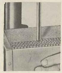
BORING EVENLY SPACED HOLES
Use of Spacing Blocks
When it is necessary to drill a series of holes in sequence, excellent use can be made of pre-cut spacer blocks in conjunction with a fence. Cut blocks to the exact dimensions of the hole spacing and place them between end of work and a clamped stop block. Then remove blocks one at a time as the holes are drilled. If hole spacing is irregular, cut and assemble blocks accordingly.
A parallel row of holes to the same dimensions may
spacer block to be used against the fence.
Use of Spacing Jig
An alternate method of drilling equally spaced holes in series employs a simple jig. The first two holes in the work are laid out and drilled in the usual manner. A locating block with a removable pin is then placed so the pin will enter the first drilled hole while the second hole is lined up with the bit. The locating block is secured to the fence at this position and the pin used to fix
the position for sub-
Use of Pivot Pin Evenly spaced holes in a circle are bored with the aid of a pivot pin set into a scrap board which is clamped to the table. Work is placed over pin after boring a blind or through hole at center of circle. Rotate

work and anchor it in position for next hole with a second pin inserted through last hole bored and into scrap board at the desired distance from the bit.
BORING IN ROUND WORK
The drilling of round or cylindrical pieces requires the use of a fixture of some type to prevent the work from rolling under the pressure of the drill. A homemade V-block does very well for cylindrical pieces. In use, the V-block is located on
the table so the drill lines up exactly with the center of the V. When clamped in this position, holes can be drilled in any size piece of round stock with assurance
a center head. This chucked drill and the scribed line and the c drilling is started. For rough work, a hole can be drilled through a circular piece if it is centerlined as above and held against a fence for a steady rest.
The edges of large circular pieces or discs can be drilled radially by using two bolts and the tilting table. With the center head, mark a centerline across the face of the disc, then tilt the table to the

ter. Round pieces may be drilled in the drill vise if the centerline is first scribed across the end with a center head. This mark is then aligned with a chucked drill and the work clamped in the vise. The scribed line and the drill are lined up by eve as the
vertical position, and loosely attach two bolts to the table so the heads project from the outer surface. With a drill in the chuck, lower the quill and lock it in a position that enables the centerline on the disc to be lined up with the drill. Manipulate the bolts and disc to this position, then tighten the nuts. It will be apparent that this set-up forms the equivalent of a V-block, and any other holes drilled in the rim will automatically be on center.
END BORING
It is sometimes necessary to drill holes in the end of a long piece, and the chief difficulty of this work is the matter of support. A very practical solution to this problem is the adjustable work support illustrated. The support consists of a bracket which clamps to the drill press column and supports an adjustable fence which slides in or out to accommodate work of various dimensions
BORING SCREW HOLES
When two pieces of work are to be assembled with screws, it is necessary to drill two holes for each screw. One hole is drilled through the upper piece and is large enough to pass the shank, or body, of the screw. The lower piece into which the screw will be


threaded — is drilled with a core hole smaller than the first. The core hole will vary with the size of the screw, the kind of wood, and the direction of the grain. As a rule, core holes in end grain should be smaller than those in side grain, as the threads have less holding power when screwed in the ends of wood pieces. When the work is already assembled, the larger shank hole is drilled first and the smaller core hole drilled down beyond it. In this manner, the smaller drill is located by the hole made by the point of the first. Consult the table of drills for wood screws on page 32 for correct hole sizes
COUNTERBORING AND COUNTERSINKING
Counterboring
Counterboring is the process of enlarging the outer end of a drilled hole, usually for the purpose of accommodating the head of a bolt or screw which must be sunk below the sur-
face. In woodworking, the enlarged portion of the hole is drilled first, since wood bits do not track well in previously drilled smaller holes. The smaller bit will center accurately in the point hole made by the larger drill. When the counterbore extends nearly through the piece, a counterbore made with a rim bit will give a stronger section as this type of bit does not have spurs to cut
below the counterbored sur-
Countersinking
Countersinking is similar to counterboring, except that the
counterborng, except that the lead of a flat head screw, permitting the screw head to be sunk flush with the work surface. When countersinking a series of holes in the drill press, it is good practice to set the depth gauge for uniform depth of cutting. Center each hole by lowering the countersink into it while countersink is stationary.


& 60° COUNTERSINK
BORING BARS
metal drilling
DRILL SELECTION AND SPEEDS
Although there are many styles of drills for special purposes, the twist drill (commonly called "drill") is most generally used in the average shop for metal drilling. This drill has two flutes, two cutting edges, and either a straight or tapered shank. The straight shank drills up to 1/2-inch diameter are most popular because they can be held in the Jacobs chuck. Tapered shank drills require the use of an adaptor socket. When used, the adaptor should be locked on the spindle with the knurled collar.
Twist drills are made in three series of sizes: The fractional series, the numbered series, and the lettered series. With few exceptions each series provides a slightly different selection of sizes, with the result that there is a drill size for practically any desired hole, within a few thousandths of an inch. Numbered and lettered series drills available are list-
ed in the tables on page 31. Fractional series drills are usually made in 64ths of an inch, from 1/64 up to about 11/4-inch diameter.
Twist drills are made of either carbon or high-speed steel. Carbon steel drills give excellent results for most work, if care is taken not to burn them up, and are less expensive. High-speed steel drills may be operated at higher speeds and in harder metals, stay sharper, and last longer. The latter should be used in drilling monel, stainless and other tough steels, and are more satisfactory for use in fibre, hard rubber, asbestos, bakelite and similar plastic materials.
The speed at which a drill is operated is very important to drill life and the quality of the work. Proper press speeds for various metals and drill sizes are given in the table on page 32. As listed, these speeds are correct for carbon drills; for high-speed drills, double the speeds given.


STEP-BLOCK

PIPE V-BLOCK

V-BLOCK


V-BLOCK


PROPER FEEDING AND HOLDING OF WORK
On most presses the rate of feed must be judged by feel, and by observation of the chip. Avoid the common error of using too slow a speed and too heavy a pressure. Apply a firm, steady pressure until drill is about to break through, then ease off
Large pieces, in general, can be held with the hands; but it is much better practice to hold work securely by some mechanical method. Small pieces and thin sheet-metal pieces, especially, should be firmly secured, as the break through of the drill, coming suddenly, can easily pull work from hands causing severe cuts and breakage of the deill
A simple method to stop rotation of flat work is to fix a clamp or bolt in a slot of the table. and hold work down against it (1). Two such bolts at opposite corners of work, are even better. Actual clamping devices can be of many types. depending upon ingenuity of operator. Among suggested devices are the grooved edge V-block and Y-clamp - an excellent combination for holding round pieces (2). Irregular-shaped pieces can iron together with the common C-clamp (3). Parallels, used in conjunction with long bolts anchored in the work table to act as stops (4), and to have many uses. Then there is the much used strap clamp (5), which can be purchased or can be made at home from a length of suitable strap lection off odd-shaped pieces, any one of which job. The main purpose is to obtain a solid firm level mounting of the workpiece. It is also important - especially when drilling thin pieces - to avoid spring or give in the work under pressure of the drill. Use wood blocks to properly support area under drill, if there is any tendency of work piece to sag.
A drill vise offers special conveniences in holding work. Often, it can be held by hand, as it affords the necessary grip and leverage to prevent work from turning. In precision work, however, the vise should be secured to table with a C-clamp, or by bolts through the vise lug. If possible, place work in vise so that drill is above vise channel; otherwise, put a scrap of wood or soft metal under location of hole to prevent drilling into the vise. To end bore long pieces, clamp vise to table and tilt table 90 degrees. The auxiliary Vjaw and wedge-shaped jaw are both very useful for holding irregular-shaped work.


metal drilling continued


The milling vise is the finest of holding devices. Offering all the advantages of the drill vise, it also affords the added convenience of easy and accurate work positioning under the drill. When exact positioning of holes on one surface is important, both

layout and drilling can often be accomplished on the milling vise. Layout can be done with a pattern fastened on top of work, or by calculating movements of the vise jaws. If hole sizes are to be different, it is common practice to spot all the holes with a center drill,
drilling to the finished sizes after the spotting layout has been made. The jaws of the milling vise take most types of work likely to be performed in the drill press, but if the workpiece is of a character which makes use of the jaws impractical, these may be removed and the part can be clamped to the vise table by one of the methods previously described.
BORING CENTER HOLES
The combination drill and 60-degree countersink, also called a center drill, is very useful for boring center holes in work to be mounted on a lathe and for spotting and drilling starting holes for the larger drills.
STARTING A HOLE
A center-punch mark should always be made before starting a hole in metal. If this is not done, the drill may wander before penetrating the metal, and may break; or the hole may be off-center. When the larg-

er drills are used, a centerpunch mark may be too small to guide the chisel point of the drill accurately. In such cases, the hole may be started with a smaller drill or with the center drill. It is good practice, whenever accuracy is important, to layout on the work a checking
circle of same size as hole to be drilled so that progress of hole can be observed.
DRIFTING A HOLE
If drill wanders off exact center, first try to determine cause. The table and/or work surface may not be level. Or, the center-punch mark may have been at fault. In most cases, however, an improperly sharpened drill is to blame. Correct original cause before proceeding, if possible.
To correct the hole, use a cape chisel and cut out some metal on the side toward which the drill should return. When drill is again entered into the work, it will tend to drift to the chiseled side of the hole.
SPOT-FACING AND COUNTERBORING

Spot-facing and counterboring are similar in that the hole itself is not changed in any way, but the surface around it is cut away. Spot-facing consists of machining a round, smooth surface at the face of the hole where it is desirable
to have a flat seat for a bolt head or nut. This is generally done on castings and other irregular surfaces. Counterboring is simply a deep spotfacing operation and permits, for example, recessing a bolt head below the surface. Both counterboring and spot-facing

are generally done with the counterbore, a special tool available in sizes for all standard screws. Counterbores can also be made by drilling small hole for screw shaft, first, then drilling larger top hole for screw head. Resulting counterbore will then have tappered bottom edge.
COUNTERSINKING
Flathead screws are designed to be sunk flush with the surface of the part they enter. To provide a tapered recess in a drilled hole for this purpose, it is necessary to use a countersink. Center reamers or machine countersinks, with an 82-degree angle are widely used for countersinking, as is the rose countersink which is shown in the illustration. Countersinking is usually done at the same speed as drilling. provided, of course, that both drill and countersink are of like material
REAMING
When it is necessary that a hole be of an exact diameter, it is first drilled slightly undersize — about 1/64th of an inch smaller. The finished size is then obtained by use of a reamer, which is run through
the drilled hole at a speed approximately two thirds of drilling speed. The reaming is done dry in cast iron and brass, but the recommended lubricants, as listed an page 32, should be used for other metals. Reamers are not designed

for the indiscriminate enlarging of holes, and should not be used to remove large amounts of metal.
BORING
Holes are sometimes enlarged by boring. This operation is performed with a boring bar — a metal rod or shaft which holds a cutting tool at the working
end. The boring bar should have a 1/2-inch shank, and be mounted in a 1/2-inch collet chuck. Boring bars with a screw adjustment to set the depth of cut are the most satisfactory; but the simple type shown in the illustration can be made in the home shop for

occasional use. When boring in the drill press, take very light cuts on each pass to prevent chatter.
APPING
Lapping a hole is a process similar to reaming, except that the cutting agent is an abrasive material instead of steel cutting edges. The lap is a round metal rod charged with abrasive grains. It is of
a softer material than the work. This lap, before charging, should be no looser than a good turning fit in the hole. Charge the lap by rubbing it with the abrasive or (for best effectiveness) roll it between steel plates, one of which is coated with the abrasive material. Laps should be run at slow speed with plenty of lubricant. A light lubricant permits faster cutting, but results in a coarser finish than is given by use of a heavier oil

HONING
Although honing is a highly specialized process generally requiring the use of specifically designed equipment, small hones can be used in the drill press to correct out of roundness and bell mouth within tolerances of approximately one thousandth of an inch. Special coolant is available and must be played upon work in a steady stream. Work is accomplished entirely by feel and must be constantly checked from start to finish. Most manufacturers of hones will supply detailed instructions.

BRASS TUBE BRASS TUBE BOTTOMING TAPS BOTTOMING TAPS SHARPENED DRILL ROD FILE TWIST DRILLS PLUG TAP STARTING TAPS
miscellaneous drill press operations .
GLASS DRILLING
Holes may be drilled in glass by either one of two methods. One procedure employs a steel or brass tube of the same size as the intended hole, and slit at the working end. A circular dam of putty is mounted on the surface of the glass around the hole area. Then a quantity of 80-grit silicon carbide, in a liquid mixture with turpentine, is poured into this reservoir. The drilling tube is driven at a speed of about 500 rpm, and a light but even pressure is maintained on the feed handle. (Unless the surface supporting the glass is dead level, the glass may crack under drill pressure.) Lift the drilling tube from the work regularly to permit new abrasive to flow into the cut. Do not drill through, but turn glass over and firish from reverse side, if perfectly clean hole is desired.
Small holes may be drilled with a hardened piece of drill rod ground to a triangular point, or with a triangular file. Lubricate the drill with turpentine in which some camphor has been dissolved. Drill half-way through, then reverse work and drill from the opposite side.
PLASTIC DRILLING
Acetate and acrylate plastics can be drilled with ordinary twist drills for metal; but, for the best results, the drills should be repointed to work with a scraping rather than a cutting action. Consequently, the drill point for plastics should be ground to an angle of about 140 degrees instead of the usual 118 degrees, and the lead of the drill should be reduced to limit its tendency to hog into the work. Moderate speeds should be used, and the drill must be lifted from the hole frequently to prevent clogging or burning. If the work will be exposed to variations in temperature, it is advisable to drill bolt or rivet holes slightly larger than required to allow for expansion and contraction. When drilling thermo-setting plastics, lift drill often to avoid raising temperature to melting point of the material.
STARTING TAPS
When tapping through thin sections of metal, such as tubing, etc., the drill press may be used to advantage in starting the tap straight. After drilling the hole, use a countersink to make a cut about 1/32 inch deep. This helps start the tap and eliminates need for removing burr raised by threads at top of hole. Fit a starting, or plug tap into the chuck, bring it down to the hole, and turn the quill by pulling the belt by hand. Do this slowly and carefully to prevent tap breakage. When the tap is started in the hole, release it from chuck and finish work on the bench.
There are three common types of taps: Starting, plug and bottoming. The plug tap is the most widely used for all-around work, but the other two are essential for some types of work. To produce cleaner threads and reduce tap breakage, a starting tap should always be used first when tapping into hard or tough metals, such as some of the bronzes, monel, stainless or tool steels. Bottoming taps are necessary to produce a full depth of thread to the bottom of blind holes after preliminary threading with a starting or plug tap.

ROTARY PLANING
Several types of small rotary planers, usually with adaptors for 1/2-inch chuck spindles, are available. The planing set-up requires use of a fence attached to the back edge of an auxiliary board on which work will slide. Board is positioned as necessary and clamped to table, which must be level. Start with quill fully raised and locked, and raise table to position work. Operate planer at 5000 to 9000 rpm. Take very light cuts. If more wood must be removed, reset quill for second cut. Feed from left to right.

CUTTING PLUGS AND DOWELS
The plug cutter is a specialized bit, usually with a 1/2-inch shank. It can be mounted in any 1/2-inch chuck, and is designed for cutting thin plugs, or
dowels up to about 2 inches long. Plugs, used for capping screw holes, are always cut with the grain running across the diameter — at a tool speed of approximately 2400 rpm. Dowels are cut with grain running lengthwise — at a tool speed of approximately 1300 rpm.

DAMASKEENING
All that is required for damaskeening, or spot finishing, is a hard rubber rod of suitable diameter and some abrasive grains such as emery, aluminum oxide, or silicon carbide of about 150 grit. Mix grains with oil and spread resulting paste on work. Then lightly press revolving rod to surface.
Speed should be about 1500 rpm, and feed should be of uniform pressure and duration. Work out a pattern in advance, and use guides to achieve uniform spacing. A pencil eraser can be used on soft metals
SPINNING RIVETS
A punch and anvil, of same type used for hammering rivets, can be used for spinning hollow rivets on the drilt press. Bolt anvil to table and insert punch in the chuck. Punch should turn at approximately 1300 rpm. When work is placed with rivet head in anvil, two or three light hammer-like

blows with the revolving punch are administered by using feed handle. Rivet must be a snug fit for good results.
MIXING PAINT
A coat-hanger wire, bent as shown, can be used in drill press for easy mixing of paint in the can. Punch hole in center of can top and pass wire through it — then be sure to put top tightly back on can before starting.press. Hold can in hands and operate press at slowest speed.

COLLET CHUCK CARVING ROUTER BIT ADAPTER STRAIGHT ROUTER BITS CONE CUTTER
router bits
TOOL SELECTION
Router bits are designed to cut grooves in the workpiece face, or notches in the workpiece edge. These bits have shanks (generally 1/4 or 1/2 inch) like drills; but they cut on the side (horizontally) instead of on the end. The two standard types are the straight bit, used for grooving, and the dovetail bit, used for dovetail notching. Other shapes can, however, be purchased; or can be made by reforming standard bits to the requirements of a special grooving, notching or carving operation.
SETTING UP AND SELECTING SPEEDS

Hold bit in a collet chuck and lock chuck securely to drill press spindle with the knurled collar. Do not use Jacobs or similar chuck which cannot be locked to spindle; such chucks will loosen under the side pressure of routing operations. Remember that tendency of bit will be to twist workpiece in clockwise direction, and arrange guides, whenever possible, at left side of line along which work is fed to bit. Operate press at not less than 4000 rpm for grooving or carving hard woods; at ap-
proximately 5000 rpm for grooving or carving soft woods; and preferably up to 9000 rpm for all operations.
FEEDING WORK
For best results, do not cut deeper than 1/4-inch in hard wood or 1/2-inch in soft wood in a single pass when using straight bit. To cut deeper, use a fence or pattern as a guide, make one pass, reset bit to

greater depth and make a second pass — and so on. Always lock quill after setting bit to proper depth — do not use feed handle if you desire uniform depth. When using dovetail or special bit, lock quill at desired finished depth of cut, and feed work slowly to
prevent bending or burning of the bit. To start a groove inside the edge of a workpiece, first drill proper size hole to correct depth at one end of groove, then start router bit in hole. Do not drill with the router bit.

GROOVING OPERATIONS
Grooving with Grain
It is essential to use a guide to obtain true, straightline grooves. Though an adjustable fence is best, any straight-edge lumber scrap bolted to work table will serve the purpose. Place fence between bit and column, and feed work from side opposite feed handle.


When cross grain grooving to work table it is necessary to use an auxiliary board with a built-in sliding back stop. Bolt or clamp board to table work into the bit at angle desired. Anchor (pin) points can be used to keep work from sliding: or a suit-
able wood block can be clamped to back stop so
rooving Circular Cuts

Perfect circle grooves are made by using a pivot, which can not objectionable) or partially into underside. A dowel or stout nail with point ground
true will serve as pivot. Fix pivot in flat board of suitable size to hold workpiece, and fasten board to work table with C-clamps.
Grooving Freehand Curves


For inside and outside curves use a flat board having a 11/2 center, and clamp board work table with dowel behind bit. Make pencil mark on fence, or dowel, exactly behind center of bit. Lock quill at finished depth of cut; if cut is too deep, pattern method must e used as only one pass can e accurately made by this freeside opposite feed handle, while constantly keeping edge of work in contact with pencil
For outside curves only, use a
Grooving Pattern Curves
A pattern can be made for any shape of continuous groove. It can be of any sufficiently rigid material

can be a saw-cut template or a p
grooved workpiece. A wood or metal pin fixed in a flat board auxiliary table guides the pattern. Pin must be low enough for pattern to ride over it. Clamp board to work table with side of pin that is nearest column in line with same side of bit. Nail or otherwise se cure backside of pattern to underside of workpiece: then place pattern over pin. Pull work outward to maintain constant pressure against backside of pin, while feeding work from side opposite feed handle. Make as many passes as necessary to obtain desired
PARRETING
All grooving operations become rabbeting if cut is along edge of work. A semi-circular cut-out in fence or guide ac commodates swing of bit otherwise operations are same as grooving operations.
ROUTER MORTISING

A short straight groove made deep enough, or cut entirely through workpiece, will hold the tenon of a mating board to form a mortise joint. First, layout

router bits continued

the groove; then, at the end of the groove, drill a hole to the depth desired and of proper size to take the router bit. Setup the routing operation by clamping fences or guide boards to the drill press table so that workpiece will slide between them, and anchor a third board between these guides to stop the workpiece when end of groove is reached. A spacer block placed between end of workpiece and stop can be used to locate start of cut, if desired.
Make as many passes as required, always starting in the drilled hole and working up to the stop. Cut the tenon with a saw. If square corners are desired, the ends of the mortise groove can be cut out with a chisel. The easier method, however, is to round off the corners of the tenon on a sanding disk so that tenon will fit the groove.
DOVETAIL GROOVING

A straight cross-grain groove cut with the dovetail router bit will hold a wedge tenon cut on a mating board to form a lapped dovetailed joint. First cut the groove. This can be either the full width of the board; or can extend part way across board from one edge. Then measure and cut the wedge tenon on a circular saw and clean out the inside corners with a chisel, if necessary. The tenon can be either at the end or on the edge of the board, as shown in illustrations.
EDGE SHAPING
Rounding off the top edge of a straight or curved cut is easily and quickly done with a carving router

bit. These carving bits are of two kinds: Those with a pilot, and those without a pilot. Bits with pilots are used without guides for edge shaping, as the pilot (which has no cutting edge) serves to guide feeding of the workpiece and regulate the depth of cut. Bits without pilots can be used like straight router bits and can also be used for edge shaping with a guide pin. The pin can be of wood or metal, and is fixed in a flat board that will cover drill press table when pin is approximately under spindle. Clamp board to table with that side of the pin against which workpiece is to be pressed lined up vertically under the same side of the tip of the
carving bit. Then, when work is pressed against pin, narrow part of bit will just touch work and wide part of bit will cut into top edge of work. Always feed work against the clockwise rotation of the bit.

CARVING
Carved flutes, reeding and designs of all types can be cut with straight, dovetail or the carving router bits without pilots. Work can be freehand, with or without the use of guides clamped to the work table; but better work can generally be done by using patterns as described under "Grooving Pattern Curves". When working freehand, keep hands out from under the bit. Small special shape cutters of the kind used with hand rotary electric tools can be held in a collet chuck and be used

to excellent advantage in making intricate designs. Use very light pressure in feeding work to the tool to avoid bending the small diameter shank. Depth variations, if desired, can be obtained by operating the dtill press feed handle; otherwise lock quill for a fixed depth of cut.


HOW DOVETAILS ARE CUT AND USED
Dovetail joints, like those commonly used on desk and dresser drawers, are cut with the help of a dovetailing fixture. This fixture consists of certain metal parts, generally sold in one package called "Dovetailing Attachment," together with a homemade wooden jig to which the attachments are secured. The packaged attachments are: A hardened steel comb, a router stop, two end brackets with one wide and one parrow stop bracket for each a

blacket for each, a hold-down bar and a hold - down channel, and springs, clamp knobs, bolts and screws for assembling these parts. Inasmuch as the quality of the finished work is largely dependent upon the exactness with which the fixture is made, use of a makeshift comb, stop and end plates is not recommended
With the fixture, both pieces of wood to be joined are cut in one operation. This ensures making a perfect joint.
TOOL SELECTION AND SPEED
Practically all dovetails are cut with a 1/2-inch dovetail bit having a shank to fit a 1/4-inch chuck. Standard attachments are designed for this one bit alone and use of other size bits would require special attachments. As in all routing operations, the bit must be held by a collet chuck secured by the knurled lock collar.
Work can be done rapidly if a high spindle speed is used; and, generally, the higher the speed the cleaner the work, as this will insure against undue tearing. Recommended spindle speeds are 5000 to 9000 rpm. Lower speeds can, however, be used if workpieces are fed very slowly and carefully.
MAKING THE FIXTURE
These directions are for preparation of a fixture using a standard dovetailing attachment. Cut two pieces of 3/4-inch plywood to exact widths of 9-7/16 inches. Width is important if attachment parts are to fit properly. Pieces can be any length; good sizes are 10 inches for one and 12 to 15 inches for the other. Secure the two pieces together with a box joint, securely fastened with screws, and make certain that all mating edges are flush. The longer piece will now be the horizontal part of the fixture, with the shorter piece projecting downward. Assemble
dovetailing attachment cont*d

one narrow stop bracket to the horizontal part of each end bracket, and one wide stop bracket to the vertical part of each. Then mount each end bracket group to its respective end of the fixture, as shown in the illustration. Loosely mount the hold-down bar to the two narrow stop brackets, and the holddown channel to the two wide stop brackets, leaving these ready for insertion of the workpieces. The comb and router stop are mounted later.
SETTING UP THE WORKPIECES
Cut the two workpieces to exact size to make them ready for dovetailing. When one piece is thicker than the other — as is generally the case when a drawer front and side are being dovetailed — place the thicker piece flat on the horizontal top of the fixture, with the face intended for the inside of the drawer on top. Place thinner piece against vertical face of fixture, with the side intended for the inside facing out. Butt both pieces firmly against the respective stop brackets at the left side of the fixture, true up the top edge of the vertical piece to make it flush with the top side of the horizontal piece, and

secure both pieces by tightening the hold-down clamp knobs. In tightening the hold-downs, draw them down equally at both ends so that workpieces will be firmly held; but do not overtighten them to the extent of distorting the fixture. When secured to the fixture the vertical workpiece will be offset to the right of the horizontal workpiece because of the wider vertical stop bracket.
SETTING THE GUIDE AND ROUTER STOP
Starting at the edge of the horizontal workpiece (where it butts against vertical workpiece), measure in a distance equal to the thickness of the vertical piece less 1/8 inch. Draw a line parallel to edge at this distance. Now hold a flat board against the vertical workpiece so that it projects up above the hori-

zontal piece, and place the comb on top of the holddown bar with outer rounded edges of the teeth touching the flat board. If the drawn line is visible between the comb teeth, when looking straight down, this is the proper comb setting. In this case, hold comb in position and place router stop on top of it with edge of stop directly above the drawn line. Slots in router stop and comb must be aligned with screw holes in hold-down bar; and washers and screws are now used to firmly secure comb and stop in position.
If comb hides the drawn line, move it back until line is barely visible at innermost edges of slots between comb teeth, and secure it in this position without using the router stop. Comb slots will serve in place of the stop, in this case.
Check all comb and stop settings carefully. Exact settings are important as even 1/32 inch one way or


the other will make a poorly fitted joint. The router bit must cut into the horizontal piece at the bottom (the widest part of the dovetail bit) a distance exactly equal to the width of the vertical piece. Being 1/2-inch wide at the bottom.
and being mounted on a 1/4-inch shank, the cut taken by the bit will extend 1/6-inch [1/2 x (1/2 - 1/4)] beyond the point at which the shank strikes the stop (or comb). This is the reason for drawing the line to which the stop is set exactly as described.
SETTING GUIDE FOR LIPPED DRAWER
The setting already described is for a flush joint. Frequently, however, drawers are made with a small

projecting lip at edges of face to provide a neat fit at the front without binding at the sides. When setting the comb and router stop for this type of joint. move the pencil line in from the edge of the horizontal piece by an added distance equal to the exact width of the desired lip. After dovetail is cut, lip can be formed on edge of drawer front by cutting away excess wood with a circular saw or dado set.

CUTTING THE DOVETAIL
Of similar importance is the exact setting of the depth ofcut. Place fixture on drill table and set quill for a 3/8-inch deep cut, as measured on side of vertical workpiece. Lock quill.
Place fixture on drill table with vertical workpiece on left side. Then rotate table to bring work in approximate position for feeding it to the bit. As

it is absolutely necessary that fixture be kept flat on table top during cutting, it will be helpful to place a heavy weight on top of that part of fixture or workpiece that is above the table. Start at either right or left side and pull work into bit until bit shank is as far inside the end slot of the comb as it can go. From now on until finished, keep bit shank in contact with edge of comb, so that bit enters wood to full depth of each slot; but do not use more force than necessary. Move progressively from slot to slot until entire dovetail is cut.
It may be necessary to turn and twist work to avoid striking the drill press column. If so, plan how work is to be fed to the bit before starting, or practice with scrap lumber. Use of a column collar to support the table and permit changing the table position when half through a cut will make cutting of wide dovetails easier. Do not, however, allow table to swing free while feeding work to the bit.
If necessary, work can be moved to opposite side of table and be fed to the bit from other end of fixture, to complete a half finished cut.
Cut right front and left rear drawer corners at one end of fixture; then cut other two corners at other end. Rub vaseline on comb edge to reduce wear of comb and bit shank.


shaper and milling cutters
TOOL SELECTION AND SPEEDS
A great many styles of shaper cutters are available and the drill press can be used very successfully for a wide variety of shaping operations merely by the addition of a homemade auxiliary wood table. The shaper cutters are mounted to the spindle with an adaptor that is locked in place by the knurled collar. Most shaper cutters have 1/2-inch bores; but some cutters have 5/16-inch bores, and other special bore sizes are available. The table can be made of 3/4-inch plywood, as large as desired, and should be fastened to the drill press table with countersunk carriage bolts. It should be fitted with recessed nuts for attaching a shaper fence and a hold-in.
For best results, the press should be equipped with a multi-speed attachment allowing speeds up to 10,000

rpm. The higher speeds produce clean, smooth work. Speeds below 4000 rpm are not recommended.
PROPER SET-UP AND FEEDING
Most shaping operations can be performed with the drill press head in the usual position, but some classes of work can be done best if the head is removed, inverted, and remounted underneath the table. The adaptor spindle and cutter will then project through the center hole in the table. (If motor is removed during change-over procedure, be sure to put V-belt down over column before replacing head and table.)
Work is always fed to the revolving tool against the direction of its rotation. With the head in normal position, work will normally be fed from the side opposite the feed handle. If the head is inverted,

the feed direction is reversed. If it is desirable, for any reason, to reverse this normal direction of feed, simply reverse the electric drive motor and cutters. Do not attempt to remove too much material in one cut; but make several passes if necessary to complete work.


STRAIGHT EDGE SHAPING

requires the use of a shaper fence. This is a fence that has two wings with a gap between them to allow for the swing of the cutter. At least one of the wings should be adjustable in or out; some fences have both wings adjustable. The fence should also have a holddown attachment. Not only does this fence serve to guide the work; positioning it to enclose more, or less, of the cutter determines the depth of cut.
Shaping a true straight edge
Always avoid long extensions of the quill as a heavy side thrust is developed in this type of work. Move drill press table up on column to as close to desired position as possible then complete the setting for vertical position of the cutter by lowering guill with feed handle. Lock the guill. Position fence, for left-to-right feed, so that workpiece pressed against left wing will be fed to cutter at desired depth of cut, then adjust right wing to guide shaped workpiece after it has passed over the cutter. Reverse settings for a right-todowns and hold-ins whenever possible.
CURVED EDGE SHAPING
Curved edge shaping is generally done with the aid of shaper collars. Though solid collars can be used, it is much better to procure or make a set of bearing collars. This consists of a number of flanged metal rings which rest together over an inner collar of bronze, which acts as the bearing. The rings can be added

diameters. Since the inner collar can revolve within the outer rings, the outermost ring remains practically stationary on the work edge, eliminating the burning or scoring caused by solid collars.


PATTERN SHAPING

Feed work carefully into the revolving cutter until stopped by the collar — then keep it in solid contact with the collar throughout length of cut. When the cutter first strikes the work, there is always a slight kickback. This can be controlled by using an anchored starting block at left side of work to take the kickback and afford leverage. After starting, swing work to right, free of starting block, and continue operation.
If the entire edge of the curved piece is to be shaped, there is no bearing surface for the collar and a pattern must be used. The pattern is cut to the same shape as the work, but usually a bit smaller to permit a full depth of cut when using a standard collar. It is then nailed or otherwise fastened to the bottom of the work, and the operation is accomplished exactly as already described,
except that the collar rides on the pattern edge instead of on the work edge.


shaper and milling cutters cont'd

FLUTING
Fluting or reeding on turned work can be done on the drill press with the use of a homemade fixture. This type of work is actually a shaping operation, and a shaper cutter and collar are employed. The bearing collar is especially desirable in fluting since it will not burn the workpiece, a danger always present with a solid collar. If the work is of such a nature that collars are impractical, a flat pattern of the same outline as the workpiece can be made and secured to the bottom of the fluting fixture. A pin secured in the auxiliary wood table should be placed to permit the proper depth of cut when the pattern is guided against it.
The illustrations show the general construction details of the fluting fixture. The indexing head is drilled with 24 holes which permit spacings of 3, 4, 6, 8, 12 and 24 around the circumference of the work. The tailstock is free to slide back and forth on the bed to accommodate various lengths of work. The headstock shaft is a 5/8-inch steel rod to which the index head is pinned by a nail. A spur center is fitted to the headstock shaft. A nail through the back of the headstock engages the holes in the indexing head and thus locks the workpiece at the desired setting.
When using the fixture, any system of stops may be worked out to suit the user. Nails driven into the table and fixture base will serve very well to set the start and finish of the cut.


CUTTING ROSETTES AND BUTTONS
Rosettes are often cut into furniture panels for decorative effects. These, and ornamental buttons, may be made easily with the drill press. The cutters used for making rosettes are procurable in two or threewinged styles, sharpened on the end, and act like specially pointed drill bits. The cutters designed for making ornamental buttons are similar, but have long outer spurs to cut the button loose from the stock material. In making buttons, the thin stock is lightly glued to a wooden block with a piece of paper between the two. After the button is cut from the thin stock, it is pried loose from the paper and lifted out. When making buttons or rosettes, always set the depth gauge stop to limit the depth of cut and thus obtain uniform results.
CUTTING KEYWAYS
The cutting of keyways in shafts is a typical milling vise operation that can be performed on the drill press. The keyway cutter should have a 1/2-inch shank and should be mounted in a 1/2-inch collet chuck. A milling operation of this type requires a slow speed — about 600 rpm.
The work can be fed either toward or against the direction of the cutter rotation, but only light cuts should be taken on successive passes. If the cut is too deep, the cutter will chatter and put an excessive side thrust on the spindle.

EMERY WHEELS


BUFFING WHEEL

wood and metal finishing
GENERAL
Always mount sanding, buffing and grinding tools in a collet chuck or adaptor arbor, or on a threaded spindle with flange at top. These tools generally have a 1/2-inch arbor hole, or a 1/2-inch threaded shaft attachment. Always feed work so that wheel turns away from, not into, corners and edges. Avoid high surface speeds and long spindle extension.
DRUM SANDING
Sanding drums and discs can be made in the home shop or purchased in a wide variety of sizes. When 3-inch or longer drums are used for narrow work, such as edges, it is best to make a simple table of the type shown in the illustration. The drum can be positioned by the feed handle to utilize the whole surface as the abrasive is worn off. Drums of 1-inch width are ideal for edge work, and wear evenly when used on the average 3/4-inch lumber. Best sanding speeds are from 1300 to 2400 rpm.

PATTERN SANDING
If a number of pieces are to be edge-sanded to the same contour, it is best to make a pattern set-up. A wooden guide disc of the same diameter as the sanding wheel is fastened to the table directly below the wheel. A wood pattern of the desired shape is then formed and the stock is sawed to approximate size and secured to the pattern. By riding the pattern against the guide disc, the stock can then be sanded to the exact shape of the pattern.


BUFFING
There are many types of cloth, leather and wool polishing or buffing wheels which can be used to excellent advantage on the drill press. Both drum
and disc type wheels in many sizes are available. Lambs wool drums and bonnets (to fit over discs) are very useful for polishing waxed surfaces. Buffing wheels may be charged with various buffing compounds, generally sold in the shape of bars, for specific use in finishing different plastics

and metals. Polishing and buffing speeds range from 2400 rpm for discs to 4000 rpm for smaller drums.
SCRUB AND SCRATCH-BRUSHING
Fibre and steel wire brushes, both cup and disc types, are useful for scrubbing, waxing, carbon and dirt removing, finishing, and many other drill press operations. Wire scratch-brush-
erations. Wire scratch-brushing produces a satin finish on metals which previously have been polished; but the metals must be softer than the brush wires. It is advisable to protect the eyes with safety goggles or a face shield, as strands may occasionally be thrown

off. Brush speeds range from 1300 to 2400 rps
SURFACE GRINDING
Surface grinding on small metal objects can easily be done on the drill press with the aid of a milling or drill press vise. Small (about 4-inch) cup or re-
cessed-mounting-hole type abrasive wheels are used. These are readily mounted on the 1/2inch threaded spindle as a bushing can be used if wheel hole is larger. Wheels in many grades of grit are available. Best speed for 4-inch wheel is approximately 2400 rpm.

When milling vise is used, the vise provides the means of feeding work to the wheel. If a drill vise or other stationary holding device is used, place a column collar under table, loosen table clamp, and feed work by swinging the table. In either case, to set the cut bring the wheel, while stationary, down onto the work with light pressure — then lock the quill. When work is fed back under the turning wheel, the wheel will take a light cut across the work surface. Finish off complete surface before resetting wheel for a deeper cut.
the mortising chisel
TOOL SET-UP AND SPEEDS
Hollow chisel mortising equipment consists of a matched bit and chisel, generally procurable in 1/4-, 3/8- and 1/2-inch sizes, and a mortising housing. To make collar and the feed stop rod and collar from the drill press quill. Attach the feed stop rod to the mortising housing in the same manner that it was attached to the feed stop collar. Now hold the housing in position at bottom of quill and, with the other hand, place the Jacobs chuck on the spindle. Then move hous ing up on quill to seat it firmly, and tighten the housing clamp nut. Also, se curely seat the chuck on the spindle Loosen the chisel set screw and insert chisel into bottom of housing. Tighten chisel set screw. Insert bit up through chisel into the chuck, then position it to leave at least a 1/64-inch clearance between bit and chisel at bottom. Tighten
chuck carefully so that bit cannot be forced upward during operation. Check alignment of bit and chisel by turning spindle by hand. Minor alignment adjustments can be made by slightly loosening the housing clamp nut and tapping housing with a piece of wood. Operate 1/4-inch chisel at 4000 rpm or less; the 3/8- and 1/2-inch chisels at 2800 rpm or less. Higher speeds should not be used as there is danger of overheating and quickly dulling the bit and chisel. Also, it is advisable always to use a fence with a hold-down, as chisel will bind in wood unless workpiece is held flat and firm. MAKING THE MORTISE
Lay out the mortise dimensions on the workpiece, then set the fence so that chisel edge will coincide with this layout when work is against the fence. Adjust the hold-down to ride close on the surface of the work, and set the feed stop nuts to the depth of the mortise. Use short, successive cutting strokes, freeing chisel from work at each stroke to rid it of chips. Make the first cut at one end of the mortise, then take additional cuts until finished. The second and succeeding cuts should overlap each preceding cut about 1/3 of the chisel width. Any shape or width of mortise can be cut by properly adjusting the fence. Lock mortises can easily be cut in the edges of doors when the floor model drill press is

used. An adaptation of the support shown on page 11 will hold the door in proper position for this work. When mortising at an angle with the table tilted, it is necessary to clamp the work to the table for each cut to prevent shifting of the piece under pressure of the feed.
MORTISED JOINTS
A few of the many types of mortise-and-tenon joints are illustrated on this page. In making the beveled haunch joint, the slanting mortise is cut with the table tilted. The remainder of the mortise is made with the table leveled. The tapered mortise for a wedged tenon is made in a similar manner.


sharpening drills bits and cutters
DRILL GRINDING
The importance of properly sharpening a metal twist drill can not be overemphasized, since a drill that is incorrectly ground will break, burn, or drill off-center and oversize. Many experienced mechanics can resharpen a drill accurately by eye, but the home craftsman will save money in the long run by purchasing a moderately priced drill grinding attachment, use of which is recommended by all drill manufacturers.
Experience has shown that the best all-around results are obtained from twist drills that are pointed with the cutting lips at an angle of 59 degrees from the vertical, as shown in the illustration.
Both cutting lips must be of the same angle and both must be the same length. If a drill grinding attachment is not used, these dimensions should be checked


SHOULD BE 590

with a drill point gauge. The gauge shown is the type that fastens to a steel scale and, having graduations. can be used to check the lengths of the cutting lips as well as the angles. common with other cutting tools, the drill must have relief, or clearance, behind each cutting edge. Standard to 15 degrees, and this is measured at the heel of the cutting lip. This clearance checking the heel angle (47 degrees) against the drill point gauge setting of 59
If a drill grinding attachment is not available, a guide board can be made to fit on the tool rest of the grinder. This board should be laid out with

SWING TO -THIS POSITION
scribed lines at 59 degrees and lines at 47 degrees, the the latter setting giving desired lip clearance of 12 degrees. In use, the drill is set on the guide board at 59 degrees, with the lip against the side of the grinding wheel. From this position, the drill is rotated about one-sixth of a turn and swung to the 47-degree position at the same time. One or two light cuts on each lip usually brings up a sharp edge.
If the drill is sharpened on the edge of the wheel by eve. the end of the drill is
placed against the stone at the proper angle and then pushed upward while turning it slightly. If properly done, the combination of upward movement and rotation produces the clearance necessary.
WEB THINNING
In order to give strength and stiffness to twist drills. the web, or core, of the drill ward the shank. As the drill shortens due to weat and resharpening, the web becomes thicker at the cutting edge. This is particularly true of the larger drills and, in some cases, the web-thickness increases the size of the chisel edge cessive feed pressure necessary. Under these condi tions, it is necessary to thin the web.

sharpening drills bits and cutters continued
The spurs are filed on the inside, never on the outside. To file the spurs, use the flat side of the file with the smooth edge down to prevent cutting into the lips. The straightening and honing of bent spurs is clearly shown in the illustration.

There are two methods used for web thinning: One requires a round edge grinding wheel; the other, a square edge wheel. The round edge wheel works in the flutes as indicated by necessary to grind the cutting edges straight after thinning the web on a round wheel. The grinding wheels in most home shops are square edged, however, and As can be seen in the illustration, the back edge, or heel, of the cutting lip is ground away by the edge of
When grinding high-speed steel drills, never plunge them into water if they become hot. Sudden cooling is liable to cause grinding checks on the point, which later crumbles away under working pressure. If overheated, let the drill cool slowly in the air.
SPECIAL DRILL POINTS
Brass, aluminum, and other soft metals usually cause the drill to hog in if it is used without alteration. This tendency is even more pronounced when drilling
through holes than when drilling blind holes where the drill point does not break through. To overcome this difficulty, drills for brass and other soft metals usually have a flat ground on the edge of each cutting lip, as shown in the illustration. This flat need not be more than 1/32 inch in width. For drilling very tough materials, such as certain tool steels, molybdenum, monel, and stainless steel, the same type of grinding may be employed with good results.
SHARPENING WOOD BITS
Wood bits are sharpened with a flat file that is designed especially for the purpose. As shown in the illustration, the cutting lips are filed through the throat, not on the ends as are twist drills for metal.
MORTISING CHISEL
The hollow mortising chisel can best be sharpened with a conically shaped grinding point chucked in the Jacobs chuck. The chisel may be clamped upright in the drill vise, and the stone fed. down into the chisel; or the chisel can be fed by hand onto the stone. The inside corners of the chisel are sharpened with a triangular file.
ROUTER BITS
If the router bits are of carbon steel, they can be sharpened with a file; but high-speed steel bits must be touched up with an abrasive stick. All types of router bits should be kept sharp by honing at regular intervals. Since metal removed from the outside of a router bit changes its size, it is best to avoid sharpening on the outer surface. On some bits, such as the dovetail cutter, the outer surface must be touched to sharpen the bit. In such cases remove as small an amount of metal as possible.
SHAPER CUTTERS
- 30 -
Before sharpening shaper cutters, wash them in benzine or gasoline to remove all traces of pitch or gum
which would clog the stone. The face of each cutter should be laid flat on an oilstone as shown; this method retains the shape of the cutter. If desired, the bevel may be touched up lightly with a slip stone, but care must be taken not to alter the contours of the cutting edges.


tables
DECIMAL EQUIVALENTS
|
1/64 = .015625
1/32 = .03125 3/64 = .046875 |
1/4
= .250
17/64 = .265625 9/32 = .28125 19/64 = .296875 |
1/2
= .500
33/64 = .515625 17/32 = .53125 35/64 = .546875 |
3/4
= .750
49/64 = .765625 25/32 = .78125 51/64 = .796875 |
| 1/16 = .0625 | 5/16 = .3125 | 9/16 = .5626 | 13/16 == .8125 |
| 5/64 = .078125 | 21/64 = .328125 | 37/64 = .578125 | 53/64 == .828125 |
| 3/32 = .09375 | 11/32 = .34375 | 19/32 = .59375 | 27/32 == .84375 |
| 7/64 = .109375 | 23/64 = .359375 | 39/64 = .609375 | 55/64 == .859375 |
| 1/8 = .125 | 3/8 = .375 | 5/8 = .625 | 7/8 = .875 |
| 9/64 = .140625 | 25/64 = .390625 | 41/64 = .640625 | 57/64 = .890625 |
| 5/32 = .15625 | 13/32 = .40625 | 21/32 = .65625 | 29/32 = .90625 |
| 11/64 = .171875 | 27/64 = .421875 | 43/64 = .671875 | 59/64 = .921875 |
| 3/16 = .1875 | 7/16 = .4375 | 11/16 = .6875 | 15/16 = .9375 |
| 13/64 = .203125 | 29/64 = .453125 | 45/64 = .703125 | 61/64 = .953125 |
| 7/32 = .21875 | 15/32 = .46875 | 23/32 = .71875 | 31/32 = .96875 |
| 15/64 = .234375 | 31/64 = .484375 | 47/64 = .734374 | 63/64 = .984375 |
| DIAMETERS OF NUMBERED DRILLS | |||||||||
|---|---|---|---|---|---|---|---|---|---|
| Drill | Diameter' | Drill | Diameter | Drill | Diameter | ||||
| No. | Inches | No. | Inches | No. | Inches | ||||
| 80 | .0135 | 53 | .0595 | 26 | .1470 | ||||
| 79 | .0145 | 52 | .0635 | 25 | .1495 | ||||
| 78 | .0160 | 51 | .0670 | 24 | .1520 | ||||
| 77 | .0180 | 50 | .0700 | 23 | .1540 | ||||
| 76 | .0200 | 49 | .0730 | 22 | .1570 | ||||
| 75 | .0210 | 48 | .0760 | 21 | .1590 | ||||
| 74 | .0225 | 47 | .0785 | 20 | .1610 | ||||
| 73 | .0240 | 46 | .0810 | 19 | .1660 | ||||
| 72 | .0250 | 45 | .0820 | 18 | .1695 | ||||
| 71 | .0260 | 44 | .0860 | 17 | .1730 | ||||
| 70 | .0280 | 43 | .0890 | 16 | .1770 | ||||
| 69 | .0292 | 42 | .0935 | 15 | .1800 | ||||
| 68 | .0310 | 41 | .0960 | 14 | .1820 | ||||
| 67 | .0320 | 40 | .0980 | 13 | .1850 | ||||
| 66 | .0330 | 39 | .0995 | 12 | .1890 | ||||
| 65 | .0350 | 38 | .1015 | 11 | .1910 | ||||
| 64 | .0360 | 37 | .1040 | 10 | .1935 | ||||
| 63 | .0370 | 36 | .1065 | 9 | .1960 | ||||
| 62 | .0380 | 35 | .1100 | 8 | .1990 | ||||
| 61 | .0390 | 34 | .1110 | 7 | .2010 | ||||
| 60 | .0400 | 33 | .1130 | 6 | .2040 | ||||
| 59 | .0410 | 32 | .1160 | 5 | .2055 | ||||
| 58 | .0420 | 31 | .1200 | 4 | .2090 | ||||
| 57 | .0430 | 30 | .1285 | 3 | .2130 | ||||
|
56
55 54 |
.0465
.0520 .0550 |
29
28 27 |
.1360
.1405 .1440 |
2
1 |
.2210
.2280 |
||||
| LETTERED | DRILLS |
|---|---|
| Drill | Diameter |
| No. | Inches |
| A—15/64 | .2340 |
| B | .2380 |
| C | .2420 |
| D | .2460 |
| E—1/4 | .2500 |
| F | .2570 |
| G | .2610 |
| H—17/64 | .2660 |
| I | .2720 |
| J | .2770 |
| K—9/32 | .2810 |
| L | .2900 |
| M—19/64 | .2950 |
| N | .3020 |
| O—5/16 | .3160 |
| P—21/64 | .3230 |
| Q | .3320 |
| R—11/32 | .3390 |
| S | .3480 |
| T—23/64 | .3580 |
| U | 3680 |
| V—3/8 | .3770 |
| W—25/64 | .3860 |
| X | .3970 |
| Y—13/32 | .4040 |
| Z | .4130 |
— 31 —
| LUBRICANTS FOR CUTTING TOOLS | ||||||||||
|---|---|---|---|---|---|---|---|---|---|---|
| Material | Turning | Chucking |
Drilling
Milling |
Reaming |
Tap-
ping |
|||||
|
Tool Steel
Soft Steel Wrought Iron Cast Iron Brass Copper Babbitt Aluminum |
Dry or Oil
Dry or Soda Water Dry or Soda Water Dry Dry Dry Kerosene or Turp. |
Oil or Soda Water
Soda Water Dry Dry Oil Dry Kerosene or Turp. |
Oil
Oil or Soda Water Oil or Soda Water Dry Dry Oil Dry Kerosene or Turp. |
Lard Oil
Lard Oil Dry Dry Oil Dry or kero. Kerosene |
Oil
Oil Oil Oil Oil Oil Oil Oil |
|||||
The best type of lubricating oil is pure lard oil. Soda water is made by dissolving sal soda in water
| ouu | marci | ** | made | ~1 | dissolving | aur | souu | 111 | wuller |
|---|---|---|---|---|---|---|---|---|---|
| DI | RILLS FOR | woo | D SCRE | WS | DRILL PRESS OPERATION | NS |
|---|---|---|---|---|---|---|
|
Gage
of Screw |
Dia.
in Decimals |
Body
Hole Drill |
Lead
Hole Drill |
C'Bore
Drill |
Operation |
Speed
in R.P.M. |
| BORING (Bits up to 1/2 in.) | 2400 | |||||
| 0 | .058 | 53 | 68 | 32 | BORING (Bits up to 1 in.) | 1300 |
| 1 | .071 | 49 | 57 | 20 | CARVING WITH SMALL BITS | 5200 |
| 2 | .084 | 44 | 56 | 16 | DOVETAILING | 5200 |
| 3 | .097 | 40 | 52 | 4 | DOWEL CUTTING | 2400 |
| 4 | .111 | 33 | 52 | В | GLASS (Drilling with Brass Tube) | 600 |
| 5 | 124 | 1/8 | 52 | F | GRINDING (Engine Finish) | 1300 |
| 6 | 137 | 28 | 47 | i. | MILLING (Light Cuts Soft Metal) | 600 |
| 7 | 150 | 24 | 47 | 0 | MORTISING (Hardwood) | 600 |
| 8 | 163 | 19 | 42 | S | MORTISING (Softwood) | 1300 |
| 0 | 177 | 15 | 12 | Т | PLUG CUTTING | 1300 |
| 10 | .177 | 10 | 20 | v | SANDING (3 in Drum) | 1300 |
| 10 | .150 |
10
E |
20 | 7/ | SHAPING (5/6 in. Hole Cutters) | 5200 |
| 11 | .202 | 7/ | 30 | /16 | SPINNING HOLLOW RIVETS | 2400 |
| 12 | .215 | '/32 | 38 |
**/64
22 / |
*Speeds are for average grade of c | utters and |
| 14 | .242 | D | 31 | 64 | bits. If tool burns at these speeds, use | next lower |
| 16 | .269 | 1 | 28 | 3/64 | four-speed drill press. If your drill | press has |
| 18 | .294 | 19/64 | 23 | 41/64 | other speeds, use speed closest to the | ese figures. |
| DRILL SPEEDS IN R. P. M.* | ||||||||||
|---|---|---|---|---|---|---|---|---|---|---|
| Drill | Tool | Mild | Cast | Soft | Drill | Tool | Mild | Cast | Soft | |
| Dia. | Steel | Steel | Iron | Metals | Dia, | Steel | Steel | Iron | Metals | |
| 1/16 | 1833 | 3667 | 4278 | 9168 | 1/2 | 229 | 458 | 535 | 1146 | |
| 3/32 | 1375 | 2750 | 3208 | 6875 | 9/16 | 206 | 412 | 481 | 1031 | |
| 1/8 | 917 | 1833 | 2139 | 4584 | 5/8 | 183 | 367 | 428 | 917 | |
| 5/32 | 764 | 1527 | 1782 | 3820 | 11/16 | 168 | 336 | 392 | 840 | |
| 3/16 | 611 | 1222 | 1426 | 3056 | 3/4 | 153 | 306 | 357 | 764 | |
| 7/32 | 534 | 1069 | 1248 | 2674 | 13/16 | 142 | 284 | 331 | 709 | |
| 1/4 | 458 | 917 | 1070 | 2292 | 7/8 | 131 | 262 | 306 | 655 | |
| 9/32 | 412 | 825 | 963 | - 2062 | 15/16 | 123 | 245 | 286 | 614 | |
| 5/16 | 367 | 733 | 856 | 1833 | 1 | 115 | 229 | 267 | 573 | |
| 11/32 | 336 | 672 | 784 | 1680 | 1-1/8 | 102 | 204 | 238 | 509 | |
| 3/8 | 306 | 611 | 713 | 1528 | 1-1/4 | 92 | 183 | 214 | 458 | |
| 13/32 | 284 | 567 | 662 | 1419 | 1-3/8 | 83 | 167 | 194 | 417 | |
| . 7/16 | 262 | 524 | 611 | 1310 | 1-1/2 | 76 | 153 | 178 | 382 | |
| 15/32 | 245 | 491 | 573 | 1228 | 1-5/8 | 70 | 141 | 165 | 353 | |
| 15/32 |
245
*For |
491
carbon ste |
573
el drills. |
1228
Double |
| 1-5/8
hese speeds |
for high |
141
speed dri |
165
Ils. |
353 | |


 Loading...