

Accessories Increase Scope and Quality of Work

THE RIGHT MOTOR
You wouldn't expect a child to lift a man's load ..., then why expect an undersize motor to run your tool with the speed and power needed for smooth, rlean cutting? Power Your tool with the Craftsmar . Motor designed for the job.
THE RIGHT TOOL BASE
If your tool is mounted so it wobbles or is awkward to reach, it may produce more mishaps than good work. Sears offers a Chaftsman Tool Base designed especially for each bench tool ... a firm, substantial, proper height use that occupies a minimum space and is cary to move when necessary.

A BELT GUARD
Speeding belts and pulleys have grabby habits ... they can grab anything that flaps or floats too near. Use the Craftsman Belt Guard designed for your tool, and save yourself from such grabby, cotton-pickin' "hands".

AN ON-OFF SWITCH
Why do hazardous gymnastics trying to reach an but-of-the-way switch? If your tool doesn't have a built-in switch you can easily attach this Craftsman Dn-Cft Switch to your tool or the base ... close at hand.

FACE SHIEL
No sensible knight ever faced a javelin thrust ba@faced. Why should you go barefaced into the shower of flying missels tossed off by a high-speed tool? With a Craftsman Face Shield you can see better than yee olden knight – and won't perspire so much either.
WHY LIMIT YOUR TOOL'S CAPACITY TO A "ONE-ARM" JOB?
The turning of various types of workpieces – and lathe sanding – require different lather speeds. With an accessory speed reducer you can not only change speeds 'quickly and easily ... you also can obtain a much greater variety of spindle speeds than otherwise possible. Then, too, a reversing switch will help you to do better, easier sanding. Moreover, to accomplish all the various kinds of wood turnings your lathe can produce, you will need a full assortment of wood-turning chisels.
It will be easier and more enjoyable to produce a greater variety of work if you equip your lathe with the Craftsman Accessories designed for it.
THERE'S & RAFTSMAN KNOW HOW HANDBOOK FOR EVERY POWER TOOL
HOW TO DO MORE W
DO MORE WITH YOUR
Wood Lathe
OVER 200 OPERATIONS DESCRIBED AND ILLUSTRATED

A CRAFTSMAN HANDBOOK

TABLES
WOOD TURNING LATHE SPEEDS
| SPINDLE | FACEPLATE | ||||||||||
|---|---|---|---|---|---|---|---|---|---|---|---|
| SIZE | LGTH. | ROUGHING | FINISHING | DIA. | THICK. | ROUGHING | FINISHING | ||||
| 1 In. | 9 In. | 1350 | 3450 | 6 In. | To 4 In. | 2250 | 3450 | ||||
| 2 In. | 18 In. | 875 | 2250 | 8 In. | To 4 In. | 1350 | 2250 | ||||
| 3 In. | 27 In. | 875 | 2250 | 10 In. | To 4 In. | 1350 | 2250 | ||||
| 4 In. | 36 In. | 875 | 2250 | 12 In. | To 4 In. | 875 | 1350 - | ||||
| INDEXING | ||||||||
|---|---|---|---|---|---|---|---|---|
| DIVISIONS NUMBER DEGREES | ||||||||
| REQUIRED | OF SPACES | OF ARC | ||||||
| 1 | 36 | 360 | ||||||
| 2 | 18 | 180 | ||||||
| 3 | 12 | 120 | ||||||
| 4 | 9 | 90 | ||||||
| 6 | 6 | 60 | ||||||
| 9 | 4 | 40 | ||||||
| 12 | 3 | 30 | ||||||
| 18 | 2 | 20 | ||||||
| 36 | 1 | 10 | ||||||
FEET PER MINUTE SPEEDS FOR METAL , PLASTIC, ETC.
| MATERIAL I | ROUGH CUT | FINISH CUT | ||
|---|---|---|---|---|
| Aluminum | 200 | 300 | ||
| Bakelite | 100 | 140 | ||
| Brass-Soft | 140 | 200 | ||
| 326 | Bronze | 80 | 100 | |
| Copper-Soft | 140 | 00 | ||
| 1 | Copper-Hard | 80 | 140 | |
| 1 | Fiber | 80 | 40 | |
| Formica, Micarta | 200 | nou ve bi | ||
| 1 | Iron-Cast | 60 | 100 1 | |
| Rubber-Hard | 120 | 140 L | ||
| 1 | Steel-Cast | 60 | 80 | |
| 1 | Steel-Cold Rolled . | 80 | 140 | |
| Steel-Tool | 60 | 120 | ||
| Steel-Machine | 80 | 140 | ||
| Trafford (All Cast | ||||
| Plastics) | 300 | 500 |
| F | EET | PER | MIN | UTE | TO | REVO | DLUT | ION | SPER | NUTE | |||
|---|---|---|---|---|---|---|---|---|---|---|---|---|---|
| FEET PER MINUTE | |||||||||||||
| WORK | 20 | 25 | 30 | 35 | 40 | 45 | 50 | 60 | 80 | 100 | 120 | 140 | 200 |
| DIAMETER | REVO | IONS | PERI | MINU | TE | ||||||||
| ½ in | 153 | 191 | 229 | 268 | 306 | 344 | 382 | 458 | 611 | 764 | 917 | 1070 | 1528 |
| ¾ in | 102 | 127 | 153 | 178 | 203 | 229 | 254 | 306 | 407 | 598 | 611 | 713 | 1016 |
| 1 in | 76 | 96 | 115 | 134 | 153 | 172 | 191 | 230 | 306 | 382 | 458 | 535 | 764 |
| 1½ in | 51 | 64 | 76 | 89 | 102 | 115 | 127 | 152 | 204 | 254 | 306 | 357 | 508 |
| 2 in | 38 | 48 | 57 | 67 | 76 | 86 | 96 | 114 | 153 | 192 | 229 | 267 | 384 |
| 2½ in | 31 | 38 | 46 | 54 | 61 | 69 | 76 | 92 | 122 | 152 | 183 | 213 | 304 |
| 3 in | 26 | 32 | 38 | 45 | 51 | 57 | 64 | 76 | 102 | 128 | 154 | 179 | 256 |
| 3½ in | 22 | 27 | 33 | 38 | 44 | 49 | 55 | 66 | 88 | 110 | 132 | 154 | 220 |
| 4 in | 19 | 24 | 29 | 33 | 38 | 43 | 48 | 58 | 76 | 96 | 115 | 134 | 192 |
| 5 in | 15 | 19 | 23 | 27 | 31 | 34 | 38 | 46 | 62 | 76 | 91 | 107 | 152 |
| 6 in | 13 | 16 | 19 | 22 | 26 | 29 | 32 | 38 | 52 | 64 | 77 | 90 | 128 |
Nood Turn Inthe Citation State Citation Intection Citation President Citation State
M J Block: 0 J Block: 0 ATE A ATE A
Sanding Turnings – Use of Sanding Discs and Drums, Wood Chucks for Sanding – Buffing – Metal Polishing WOOD FINISHING ....................................
Wood Lathe
An Illustrated Manual of Operation for the...
HOME CRAFTSMAN SHOP OWNER
SELECTION AND ACCESSORIES CENTERING, PLANNING AND MOUNTING WORK – PROPER USE AND HANDLING OF CHISELS – MAKING STANDARD CUTS, SPINDLES, FACEPLATE TURNINGS, FANCY TURNINGS – TURNING PLASTICS SANDING – FINISHING – TABLES
GVER 200 ILLUSTRATIONS
A CRAFTSMAN HANDBOOK
Form No. B71 738915 A000
A MIN CST TECHNICAL PUBLICATION
Copyrighted 1972 SEARS, ROEBUCK and CO.

Of all power tools used by home craftsmen, or in industry, the wood lathe is undoubtedly the most fun to operate and the most satisfactory to use. Only on the lathe can the beginner and expert, alike, produce at one time, and all in the same continuous operation, finished masterpieces of intricate and beautiful design. To work with the wood lathe is to know the complete satisfaction of watching ideas take form under the magical touch of the chisel in your hands.
PROFESSIONAL WOOD-TURNING CHISELS

Available singly or in set of 4 that includes a 3/16-in. parting tool, 1/2-in. gouge, 1/2-in. round nose and a 3/4-in. skew. Special carbide tips stay sharp longer than ordinary steel . cut wood, plastic, aluminum or brass.
Carbon-Steel
Set of 5 includes one each of the 1/2-in. spear point, gouge, parting tool, round nose and skew. These and a 1/4-in, and 3/4-in, gouge and a 1-in. skew are also available singly. Long (10-in.) handles for easy use, and 4-1/2-in. polished blades.

In addition to spinning dreams, the lathe is also
a general utility tool. It can be adapted to the
speeds, to the turning, spinning, sanding, buff-
other materials. Though it cannot be made to
duplicate performances of the special tools de-
veloped for these various functions, it can be
used to perform a greater variety of operations
than any other single power tool.
Only one of many models of eye protectors is shown. Never use your lathe without wearing some type of face shield or goggles to safeguard your eyes.

Provide direct, concentrated light for safer, better work. Both a gooseneck and an adjustable tubular-arm type are available . to clamp onto lathe bench wherever convenient.
WOOD FINISHING
GENERAL TREATMENT
When the turned project is part of an assembled piece of furniture, finishing must be accomplished in the usual manner of applying lacquer or varnish. If the turning is complete in itself, however (such as a lamp base) various types of finishes can be applied on the lathe.
WAX FINISH
A wax finish usually is obtained with the paste form of wax, which can be applied directly to the work by means of the fingers or a cloth. About ten min. is allowed for the wax to flat out; then the piece is polished by running the lathe at low speed and holding a piece of soft cloth against the revolving spindle. A second coat can be applied one hour after the first. A wax finish also can be produced by use of the harder waxes – carnauba wax, beeswax or paraffin. These are in lump form, and are applied by pressing the lump against the revolving spindle so that the wax will become soft and adhere to the wood. After the work is evenly coated, the polish is obtained by rubbing the work with a soft cloth.
FRICTIONAL POLISH
This type of polish will bring out some measure of shine in the work, but is generally used only as an initial step for some other type of finishing. It is obtained by taking a handful of fine shavings from the work, cupping these in the hands, and pressing them against the revolving workpiece.
OIL FINISH
This means the use of hot, boiled linseed oil as the only polishing medium. The oil is brushed on; then the work is thoroughly rubbed with a soft cloth as it revolves in the lathe. Considerable rubbing is necessary to entirely dry the oiled surface.
VARNISH FINISH
The varnish finish is applied to turnings in much the same manner that it is used for any other form of cabinetwork. The finishing is not done on the lathe, with the possible exception of applying the paste filler. If required, this filler can be rubbed off at a low spindle speed
FRENCH POLISH
Best results can be obtained by using boiled linseed oil or paraffin oil, as a first coat. Other coats should consist of a polish made of pure white shellac, boiled linseed oil and denatured alcohol. These are not mixed in one bottle, but are kept in three separate bottles. A soft lintless rag (cheese cloth is good) and absorbent cotton are required. These are made into a pad – with the cotton inside – that is approximately 1/2-in. thick by 2-in, in diameter. Place the pad over the mouth of the shellac bottle, and tip the bottle to fairly well saturate the pad; then, place the pad to the mouth of the alcohol bottle and put on about half as much alcohol as shellac. Add two or three drops of oil.
Run the lathe at low speed and apply the pad lightly at first, increasing the pressure until the cloth is almost dry. Then add a little more shellac and an equal amount of alcohol, and apply again until the pad is almost dry. Repeat this operation until the whole surface of the work is evenly coated. After the first polish coat has hardened (24 to 48 hrs.) apply a second coat The second coat is usually more difficult than the first coat. Whereas the first coat can be put on with a fairly wet pad, the second and all later coats should be applied with the pad just coats, and gradually increase the proportion of shellac, using just enough alcohol and oil to prevent rings from forming on the work as the shellac piles up. Four or five polish coats give the denth of finish desired A pure water or pletely remove any oil film.
SHELLAC FINISH
This is a polished shellac surface, somewhat similar to the French polish. The lathe is turned by hand and a coat of pure white shellac is applied. The shellac is allowed to dry for about ten minutes, and then lightly sanded with worn sandpaper. Using the same kind of pad as for French polishing, moisten the cloth with a very little thin shellac and apply to the revolving work. A drop or two of linseed or machine oil can be used as a lubricant. After the necessary polish has been obtained, wash with clear water.

The drum is used mainly for sanding the edges of curved work. The squareness of the edge of the work can be best retained by using a simple form of vertical fence, as shown. The standard sanding drums are commonly made with a threaded hole to fit the grinding wheel arbor. To guard against loosening of the tapered shank while the drum is in operation, it is advisable to support the free end, using either a ballbearing or plain 60ocenter in the tailstock.
USE OF WOOD CHUCKS FOR SANDING
Quick-acting chucks can be very useful for sanding operations on duplicate production parts. The chuck is made slightly oversize, and a piece of rubber hose (for small parts) is inserted in the recess to grip the workpieces. Workpieces can be changed without stopping the lathe.
BUFFING OPERATIONS
In operations using buffs or polishing wheels, work should be held against the lower quarter of the wheel (as shown), so that the wheel runs off the work. As in all jobs involving the use of a Morse taper shank for side pressure operations, the free end of the arbor should be supported to prevent the shank from working loose. A much better set-up is to thread a

3/16-in, rod into the end of the shank so that the arbor can be held by means of a washer and wing nut at the outboard end of the spindle.
General buffing with a 6-in. wheel should be done with the lathe running at next to highest speed. The buff itself should be 20 to 36 layers of muslin. A loose buff runs soft and is good for final polishing; sewed buffs are somewhat harder. Three or four buffs can be mounted on the spindle to give more contact area. The buff is charged by holding an abrasive compound against it as it revolves. The abrasive compound can be any one of several standard types. These consist of fine abrasives bonded together to form a cake or stick. The compounds can be purchased ready-made, or can be made in the shop by melting beeswax in a double boiler and adding fine pumice, whiting, rouge, etc., to form a paste which can be made into cakes.

POLISHING METALS
Use a loose muslin buff and run the lathe at highest speed. Aluminum is buffed with tripoli, followed by red rouge. Brass or copper polishes nicely with tripoli or emery. Cast iron is polished with 240-grit silicon-carbide powder bonded with grease. There are various allpurpose polishing compounds which are generally obtainable. These can be used for all metals. They consist of very fine abrasives, such as lime, whiting or tripoli.
SHOP-TESTED ACCESSORIES
A CRAFTSMAN MOTO
Never underpower your lathe. Underpowering results in poor quality work and possible motor damage. Obtain the 1/3 or 1/2 hp 1725 rpm Craftsman motor that is recommended and you will be able to take full advantage of your athe's versatility.
A 4-STEP PULLEY
If you have not ordered your lathe with motor above, this must be ordered separately. Pulley matches one on lathe to provide 4 speeds (875-3450 rpm).
A SPECIAL LATHE WORK BENCH
Substantial but lightweight bench has large wood top that provides ample room for lathe, motor and workpieces. Can easily be fitted with a tool light and motor switch for maximum work safety and convenience.

A RETRACTABLE CASTER SET
Set includes two 2-caster assemblies for mounting on bench legs, as shown. Each has a step-on foot lever to lower or retract the casters.
GENERAL INFORMATION
DO IT CORRECTLY
For safety, as well as greater operating convenience, never wear loose, floppy clothing – no long tie, no loose long sleeves, etc. – and don't wear rings or a wristwatch. To protect your eyes from sawdust and flying chips, do wear a face shield or goggles.
Always check to make certain that work is securely mounted — then spin the set-up by hand before starting the lathe. Stand a little to one side of the cut being made, and hold the chisel so that, if thrust back suddenly, it will not strike your body. Never reach behind the lathe while it is running.
DO NOT BE AFRAID TO WORK CLOSE AND AT HIGHER SPEEDS

Keep the tool rest close to the work, readjusting it as necessary. This is important because the revolving workpiece tends to thrust the chisel point downward, thus seesawing the handle end upward and out of your hands. Your leverage – and ability to hold and control the chisel – depends largely upon the amount of chisel ("a" in the illustration) on your side of the tool rest, as compared to the amount ("b") on the other side.
Keep your chisels sharp, and don't be afraid to use high lathe speeds. Cutting is smoother and the chisel is easier to control at higher speeds, especially when turning soft woods; and there is less chance for the workpiece to snag the chisel.
YOUR LATHE SPINDLES
The headstock spindle has a 3/4x16 male thread end — for mounting a faceplate or a threaded chuck — and a No. 1 Morse female taper — for mounting centers and taper-shank chucks, etc.
The spindle is hollow end-to-end so that a 1/4x6-in, rod can be used to tap out a tightly lodged center. The tailstock has a No. 1 Morse.

POSITIONING THE TAILSTOCK
Major adjustment of distance between the headstock and tailstock centers is made by loosening the tailstock lock and sliding the tailstock along the lathe bed. Minor adjustment is made by loosening the tailstock ram lock, and using the handwheel to position the ram. Use major adjustment to space centers to overall workpiece length; then use minor adjustment to seat workpiece on the centers. Tighten both locks securely after mounting work.
![]()
ADJUSTING THE TOOL REST
The tool rest can be moved along the lathe bed, across the bed, or can be rotated 360° to position it as desired. In addition, it can be raised or lowered. These positions are secured by locks which must be tightened to hold the rest stationary when in use.
INDEXING FEATURE
Your lathe has an indexing pin on the headstock. This pin can be set to engage any one of a number of holes in the spindle pulley flange, to hold the spindle in a fixed position. The holes are arranged so that spindle can be set at all commonly used spacings for fluting, reeding and similar operations.
SANDING, BUFFING AND POLISHING
USING THE LATHE

Turnings should be sanded with the lathe running in second lowest speed. A large sheet of sandpaper is useful for smoothing cylinders. All other sanding operations are done with a narrow strip of abrasive paper. The best finishing grit is 3/0 for softwoods, 4/0 for hardwoods. Worn 2/0 paper is often used, and is the equivalent of 3/0 or 4/0 new paper.
The application of the sandpaper strip is shown in the illustrations. Care must be exercised in order to prevent dubbing the corners of beads,

shoulders, etc. It is good practice to finish sanding with the work in reverse rotation. This is particularly true when sanding basswood, white pine and mahogany. These woods are hard to sand clean since sanding packs the surface fuzz down to the wood. Sanding very lightly, and not too long, with the lathe reversed, will lift the fibers and cut them off clean.
USE OF SANDING DISCS

The sanding disc is a metal plate with a threaded shank which fits the end of the lathe spindle. Abrasive paper is glued to the machined surface of the plate by means of a quick-drying cement supplied for this purpose. Abrasive discs can be purchased or cut from the standard sizes of abrasive paper.
A fully adjustable sanding table adds to the scope and convenience of sanding operations; but good work can be done with a wooden table, made to rest on the bench straddling the lathe bed, as shown, top of page 30 . Sanding is always done on the down-traveling side of the wheel; working on the other side would kick the work upwards. Either second or third speed can be used.
USE OF SANDING DRUMS
Standard sanding drums are usually rubber cylinders which can be expanded to hold an abrasive sleeve in place. Similar cylinders turned on the lathe, and covered with abrasive paper glued or tacked in place, do satisfactory work. These have the advantage that special sizes, tapers, etc., can be made.
wood
FIBERS
HOW TO TURN PLASTICS
TYPES OF PLASTICS
There are two general groups of plastics. The names as Lucite Catalin Cast Bakelite Marharder than wood but much softer than any of
MOUNTING THE WORK
(metal-lathe) chuck. When this is not available cylinders can be mounted on a slightly tapered across the work.
USE OF FORMED TOOLS FOR PRODUCTION READING AND SIMILAR OPERATIONS

When a number of identical pieces are to be produced, all having a distinctive surface patgauge aluminum strips. A holder, like the one
TURNING BALLS

USE OF WOOD TURNING CHISELS
Standard wood turning chisels are excellent for higher than the cutting edge to give a negative rake, Scraping tools should be used. The area imum. A large contact area, such as the full edge of the spear-point chisel will cause chatter
Properly worked, the chip comes off in a continuous ribbon. In cold weather plastic may water for about ten minutes before turning
Plastic balls are rough turned in the usual manner and then brought to perfect roundness by using a tube tool. The tube should be slightly less in diameter than the finished size of the a rest, and is worked by swinging it from side to side
POLISHING PLASTICS
150-grit and 400-grit papers, in succession, used wet. Press lightly to avoid overheating and marring of the work. Buffing gives the final polish. around - otherwise the plastic might become
TWO GENERAL CLASSES OF WOOD
end of the spindle to revolve it The tailstock

A workpiece that is to be made into a disc or other large circular object having the major porthe circumference, is generally mounted on the headstock alone. Such pieces are called faceplate turnings, and are mounted on faceplates which are large enough in diameter to hold them steady.
TYPES AND USES OF LATHE
Your lathe comes fitted with a headstock spur large diameter spindles in the headstock it is useful for some plastic spindles) Other useful types of tailstock centers are the 60-degree
TYPES AND USES OF FACEPLATES
plate All three of those shown here mount on your lathe's headstock spindle by threading size can also be used as a sanding plate (to


6 1 100 5
1000
-
- 4. Work Arbor With Chuck
- 5. Chuck Arbor
- 6 600 Center
- 7. Tailstock Cup Center
- 8 Scrow Contor
- 9. Headstock Spur Center
- 10. Ball-Bearing 600 Center
- 11 Work Arbor
- 12 8-In Comb
- Face/Sanding Plate
- 13. 3-In. Face Plate
- 14. 4-In. Face Plate

A chuck, mounted in the headstock, can be other end by the tailstock center or, if short
USES OF THE WORK ARBOR
Mounted in the headstock spindle this arbor wheel, to further increase the variety of
MOUNTING & PLANNING WORK

PLANNING AND MEASURING WORK
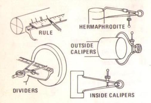
Better results can be obtained by planning the work in advance, and by taking constant measurements. This is good practice. Use the measuring tools as illustrated.
The use of gauge blocks, as illustrated, will speed the taking of measurements. Make blocks out of hardwood. Each acts as a stop for a predetermined caliper setting. Keep the knurled setting nut in the same position. Number the blocks for guick identification.

CENTERING
Accurate centering conserves stock and reduces the amount of work required to turn a workpiece down to a perfect round. If a portion of the workpiece is to be left square, accurate centering is absolutely necessary to keep the square and rounded portions in alignment. Spindle stock is ordinarily sawed square to begin with, but this is not necessary.
Perfectly square or rectangular stock can be quickly centered by means of diagonal lines drawn across each end. For square stock you can also use a homemade center marker like the one illustrated. Use 1/8-in. clear plastic cut to a suitable size square. Scribe uniform squares and two diagonals on one side with an awl. Drill center hole.
To center odd-shaped stock use a combination square – and draw one line parallel to each side, locating lines close to the apparent center. Now visually spot the center point of these

Perfectly round stock can be centered by drawing two diagonals with the use of the center head on a combination square. If stock is elliptical or slightly out of round, draw a number of diagonals, then visually select the center of these diagonals.
LOCATING FACEPLATE POSITION

A faceplate must be located on the workpiece by matching the faceplate circumference to a circle drawn around the workpiece center. Draw this circle 1/8-in. larger than the faceplate to be used so that faceplate can be positioned inside the circle.
PRE-SIZING STOCK
Generally, much time can be saved by roughsawing the workpiece to size. First, scribe a
port the ball alone, but must be used in conjuction with the tailstock. When using the shallow chuck, a wood block is fitted to the tailstock so that the ball can revolve upon it. This block should be lubricated with beeswax or grease. In using the shallow chuck method, the ball is constantly shifted – never more than 1/8 turn – and always with a definite system. Since turning between centers makes the work a perfect sphere across the grain, the ball must be mounted in the chuck so that the first scraping cuts will round it up in the opposite direction.
TURNED BOXES


Turned boxes involve deep recessing together with a special system of working the lid and body of the box together as one unit. The inside of the lid is turned first. Next, the inside of the body is turned. A careful check must be made when turning the lip of the body portion so that the lid will be a tight press fit. The lid is then pressed onto the body and the outer circumference and face of the lid, together with the outer circumference of the body, are turned all at one time. This insures accurate matching of the two pieces. After the work is complete, the tight fit of the lid can be relieved by sanding the lip of the body.
SEGMENTED TURNINGS
Segmented bowls and boxes are exceptionally attractive – and this method of preparing wood stock is more economical than the use of large solid pieces. For some types of work, segmenting is the only practical method because a block (if obtainable) would be so large that it would be very likely to warp.
The bowl illustrated requires 12 segment pieces for the sides. Bowls can be worked with 6 or 8 pieces if desired. To make the 12-piece bowl, a

board about 7/8x3x30 in. is cut into pieces about 2-1/2-in. long, the saw blade being tilted 150 and the board being turned alternately face up and face down to make the successive cuts. These 12 pieces are glued together and clamped by wrapping the assembly with wire. When dry, the rim thus formed is glued to a temporary circular backing which is mounted on the large faceplate.

A recess of the largest possible diameter, and about 3/4-in. deep, is turned in the open end of the rim. The rim is removed from the lathe, and stock for the bottom is mounted in its place on a second faceplate. This is turned to size – and a rim about 1/8-in. deep is turned to exactly fit the recess prepared in the rim. The rim is then fitted over the bottom and glued, making a drum shape with a faceplate at each end. This drum is cut completely in two at a point about 3/4-in. above the bottom – completing the cut with a hand saw. Both parts of the cut surface are faced off square and smooth – then reglued together, breaking the joints exactly half and half. The cutting and regluing process is repeated with a section about 1-1/4-in. wide. After this, the temporary backing block is cut off, leaving the bowl as shown in the final illustration.
From this point on the work is simply a matter of turning down the bowl to any desired shape.
TURNING A RING

Another method of turning a ring makes use of a recessed chuck. The work stock is mounted on a screw center and one half of the ring is formed; but the ring is not cut away from its center. The stock is then removed, and a recessed chuck — mounted on the large faceplate — is prepared to receive the ring in a tight press fit. After being chucked, the remaining face of the ring can be turned to the proper contour, thus cutting away the center portion. In work of this type take constant measurements — or better still, use a template — to guard against over or under cutting.
TURNING BALLS


One method of turning a ring requires a spindle chuck. The work stock is first mounted to a backing block held by the large faceplate, and is turned to shape on the outer side. The inside diameter of the ring is also shaped, all the way through to the backing block. The work is then removed from the backing block. A spindle chuck is now prepared so that it will be a tight press fit inside the ring, and the ring is reversed and mounted on this chuck. Thus mounted, the remaining contours can be turned to shape.


Wooden balls of large size are first roughly turned between centers, using standard procedures. Smaller balls can be mounted as faceplates on the small faceplate or screw center. Lines drawn to indicate the center and ends of the ball shape are helpful in plotting the curve. A template should always be used for accurate visual observation of the work progress.

If the ball is mounted as a faceplate turning, almost the entire surface can be turned before it becomes necessary to rechuck it. Rechucking can be accomplished in a deep cup chuck which will hold the finished portion of the ball in a tight press fit. Another method of rechucking is
circle at one end to indicate largest diameter desired for finished work, then saw off corners around outside of circle. Be careful not to cut too close to circle – at least 1/8-inch is needed for turning and polishing. Also, do not cut away any portion where it is desired to have a square that will be bigger than the largest diameter.
A lopsided piece should be trimmed at least enough to knock off the heavy side. This balances the workpiece better, and prevents the possibility of splitting the wood by gouging too deeply into the heavy side at the start.
Any faceplate turning should be trimmed before turning. This will eliminate the danger of loosening the work on the faceplate while attempting to turn down the large corners.
MOUNTING SPINDLE STOCK
With a Spur Center
The spur center is embedded into the workpiece end before mounting. Drill or punch a small hole at workpiece center to help position the center. Place the center on the workpiece, hold it straight, then hammer the end with a rawhide or wooden mallet until the spurs are firmly set into the wood. The center can then be removed for placing it in the lathe – or, to save time, it can be placed in the lathe with the workpiece attached.

If workpiece is hardwood or plastic, it is necessary to make two saw cuts in the end to receive the spurs.
Screw Centers
The end of the workpiece must be sawed flat and square with the sides. Drill a center hole just large enough for the wood to take the screw point without splitting. Turn the screw center down onto the workpiece end until face of center is firmly against end of workpiece. Mount the center to the lathe with the workpiece attached.
PLACING WORK ON LATHE

Secure the work at the headstock end (taper shank centers are thrust firmly into place by hand) then advance the tailstock, (with center in it) until center point just holds the workpiece end. Lock tailstock. Advance tailstock ram while slowly rotating work by hand, until it becomes difficult to rotate. The tailstock center will then be properly embedded in the wood. Back the ram off one-half turn to ease the pressure – and lock the ram.
When using a cup or 60-degree center, lubricate with oil or graphite. For a ball-bearing center – especially with hardwood – drill a small hole for the point.
REMOVING TAPER-SHANK CENTERS
A center is easily removed from the hollow headstock spindle by driving it out with a metal rod inserted through the spindle end. A tailstock center is removed in the same way.
MOUNTING FACEPLATE STOCK

Center the faceplate in the circle drawn on the back of the workpiece, then securely fasten it with three flathead screws. A 3/4-in. length screw will do for all but the heaviest types of work. It is good practice to notch the faceplate and mark the workpiece for relocation in the same position. When screws are objectionable, the workpiece can be glued to a mounting block. A piece of paper placed between the glued surfaces will make it easier to later remove workpiece without damage.
WOODWORKING CHISELS
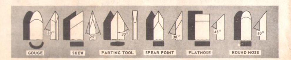
THE SIX COMMONLY USED CHISEL TYPES
SELECTION OF CHISELS
Better chisels have handles approximately 10-in. long, to provide plenty of grip and leverage. Sharp tools are essential for clean, easy work... buy tools that will take and hold keen edges.
THEORY OF TURNING
The Two Classes of Chisels

These are: 1) Chisels intended primarily for cutting, and 2) chisels used only for scraping. The cutting chisels are the gouge, skew and parting tool. These are the most used. They are commonly sharpened to a razor edge by honing on both sides. The scraping chisels are the flatnose, round nose and spear point. These are not honed on the flat sides — the wire edges produced by grinding are left on to aid in the scraping process.
Cutting and Scraping
To cut, the chisel is held so that the sharp edge actually digs into the revolving work to peel off shavings. To scrape, the chisel is held at a right angle to the work surface, and removes fine particles instead of shavings. Many operations require that the cutting chisels be used for scraping; but scraping chisels are practically never used for cutting. Scraping dulls a chisel much faster, especially the razor sharp cutting chisels.
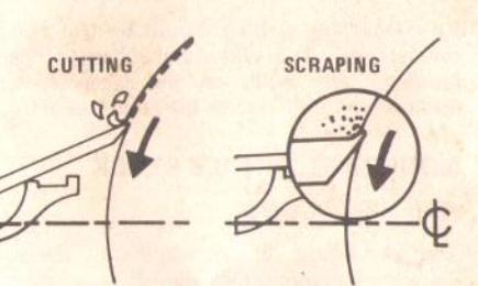
Cutting is faster than scraping and produces a smoother finish which requires less sanding. However, it is far more difficult to master. Scraping, on the other hand, is far more precise and easier to control.
When You Can Cut, and When You Must Scrape
There are two different approaches to the work when turning. One approach is toward a circumference of the workpiece (for example, turning down the outer surface of a cylinder or the inner wall of a hollow round box). In this approach, the surface being turned travels under the chisel edge like an endless belt. The second approach is toward the diameter of a workpiece (as when turning the face of a faceplate turning, or the side of a large shoulder on a spindle turning). In this approach the surface being turned rotates like a disc under the chisel edge. Sometimes the approach will be a combination of both.

HOW TO MAKE FANCY FACEPLATE TURNINGS

PREPARING A PLUG CHUCK
A plug chuck is an auxiliary wood chuck mounted onto a faceplate. The chuck can be any size in diameter – should be about 2-1/2in. thick for stability – and should be provided with a 3/4- or 7/8-in. hole in the center for receiving a tenon turned at the end of the workpiece. Once made, such chucks are permanent useful fixtures for turning balls, goblets, etc. In use, the wood stock for turning is turned between centers to produce a tenon at one end which will be a driving fit in the hole of the chuck. When mounted in the chuck, the workpiece is substantially supported for any faceplate type of turning.

TURNING CYLINDERS
Stock for cylinders should be mounted on the screw center or a small faceplate. The tailstock can be brought up to support the work while the circumference is being turned and finished. Afterwards, the tailstock is backed off and the outer end of the cylinder is recessed, using methods already described for making deep recesses.

After making a recess at least 1/2 of the way through the workpiece, and finishing this on the inside, remove the workpiece from the lathe. Now mount a short length of softwood stock on the screw center and turn this down to form a dowel that will be a tight press (not driving) fit inside the recessed end of the cylinder. Mount the cylinder on this wooden chuck, and recess the unworked end deep enough to form a perfect hole through the entire cylinder.
RECHUCKING
Rechucking is the general term used to describe any additional work mounting that is necessary to complete a turning project. The method of working cylinders, and the use of a plug chuck as already described, are typical examples. Another good example is the rechucking of a bowl.

The work is first mounted on a wood backing block secured to the large faceplate, and is turned in the usual manner – all except the back side (which is against the mounting block). It is then removed from the mounting block. An auxiliary chuck of softwood is now made in the same manner that the cylinder chuck is made. This chuck must have a turned recess properly sized to accommodate the rim of the bowl in a tight press fit. When the bowl is mounted in this chuck, the bottom can be cleaned off and slightly recessed to complete the desired contours.
FLUTING AND REEDING
This requires a lathe equipped with an indexing pin. The pin provides settings of 2 to 36 equal spacings for positioning the work (rotationwise) between lathe centers.
from the tailstock end) so that the collar will ride solid wood on all but the last cut. Slight burns created by the collar are easily removed by sanding the work after it is finished. This jig can be used on either square or round workpieces.
A typical jig for making the actual cuts is shown. This jig makes use of standard shaper cutters. A cutter is mounted and driven in the jig by means of a flexible shaft. The end of the shaft housing is firmly mounted between two blocks of wood, and is arranged to slide along a wooden guide bar of sufficient length for making complete cuts. A collar next to the cutter serves to control the depth of cut.

If the stock is tapered, the guide bar must be slanted down accordingly at one end. If the operation is reeding, each new cut should be set off by turning the work clockwise (as viewed

SPLIT TURNINGS

abinets and furniture are often decorated with ieces of half or quarter-rounds which have een cut from full-circle wood turnings.

In preparing the stock for a split turning, two pieces of wood are glued or screwed together to form a square. If the work is glued, a piece of paper should be placed between the two blocks – then, after the work is completed, a knife can be used for easy separation of the turning into halves. Screw fastenings are ideal for all short spindles; but cannot be used on very long spindles as the work will tend to separate in the center.
The assembled square stock is turned or otherwise worked in the usual manner; then separated into halves to form the decorative pieces. If quarter rounds are desired, assemble four pieces of stock, instead of two, into a square.
AND HOW TO USE THEM
Either a cutting or scraping action can be used when the approach is toward a circumference – the shaving is removed like a peeling from a potato. Scraping, only, can be used when the approach is toward a diameter. The reason is obvious when you consider that faceplate turning practically always requires removal of wood across the grain. Wood does not peel easily across the grain, and attempts to use cutting methods will likely result in damage to the work and throwing of the chisel by the work.
It follows that a cutting action is used for the general run of spindle turning operations... while the major part of a faceplate turning is done by the scraping method. When a combination approach is to be used, you will have to judge, by the feel of the work, when to stop cutting and start scraping. Never try to cut when it becomes difficult to hold the chisel against the roughness of the wood grain.
How to Position Tool Rest for Circumference Cutting
When cutting, the object is to pierce the outer skin of wood to a certain desired depth, then to hold the chisel steady, with the bevel edge parallel to the work circumference, so that it will peel off a shaving at this desired depth. The only sure method of holding the chisel steady is to rest the bevel against the work, as shown in sketch 1. When the tool rest is at the proper height (sketch 1), the chisel can be held with the bevel pressed against the work, and the tool rest will act as a fulcrum to support the chisel
against the downward force of the revolving work.
If the rest is placed too low, so that the chisel is held with the bevel out from the work (sketch 2), the cutting edge will continue to dig deeper into the work. It will dig in until the "bite" becomes so deep that your hands have difficulty holding the chisel – then the improperly supported chisel will begin to bounce, or chatter, against the workpiece.
If the rest is placed too low, the chisel must be held extremely high to position the bevel against the work (sketch 3). Then the rest loses most of its value as a fulcrum, and the downward force of the revolving workpiece tends to kick the chisel back out of your hands.
If the rest is placed too high (sketch 4) and the chisel is correctly positioned for cutting, it strikes the workpiece near the top where the direction of force exerted by the workpiece is nearly horizontal – and kickback will again result.
If the rest is placed too far out from the work surface (sketch 5) – then, when correctly held, the chisel is again too high on the work. Also, you have less leverage on your side of the tool rest – and it is even more difficult to hold the chisel. With large diameter work (sketch 6), the tool rest can be above the workpiece centerline, and somewhat out from the work surface. With small diameter work (sketch 7), the rest should be lowered almost to the centerline, and should not be far from the work surface. As work grows smaller, the rest should be repositioned.

How to Position Tool Rest for Circumference Scraping

In scraping operations, the tool rest position is not as critical as it is for cutting operations. The chisel generally is held horizontally, though it can be held at an angle to reach into tight places. Considering that the wire edge of the chisel does the scraping, sketches 9 and 10 show the results of too low or too high a position for the rest; and sketch 8 shows the chisel action with the rest correctly positioned.
How to Position Chisel and Rest for Diameter Scraping
When scraping on the diameter, that portion of surface to the right of center is moving upward (sketch 11). If chisel is placed in this area, it will simply be carried up off the rest and out of your hands. All diameter approach operations must be done at the left of center.

Three different chisel contact points are shown in sketch 12. It will be noted that, when chisel is above the workpiece center, or below it, the work surface sweeps past the chisel edge at an angle and tends to carry the chisel in one direction or the other along the rest. Only when the chisel contacts the work on the centerline does the work surface pass squarely under the chisel edge. This, then, is the position in which it is easiest to hold the chisel steady. To obtain this position, place the rest approximately 1/8-inch (thickness of chisel) below center.
USING THE GOUGE
Three gouges, the 1/4-, 1/2- and 3/4-in. sizes, are ample for general homeshop turning; but other sizes from 1/8- to 2-in. can be purchased.
The chief use of the gouge is for rough circumference cutting of raw stock down to a cylinder of working size. It is the best tool to use for rapid cutting away of large areas of the workpiece; but when so used does not produce a smooth surface. With practice, it can be used for cutting coves and the shaping of long cuts – is also useful for scraping.

When used for cutting, the gouge is always held with the convex side down. It should be rolled approximately 30° to 45° in the direction in which it is being advanced along the rest; and the cutting edge should be a little in advance of the handle.
USING THE SKEW
Two skews, the 1/2- and 1-in. sizes, are all that are needed for general use. Other sizes are available. This tool is nearly always used to make finish cuts, to cut vees and beads, and to square shoulders. Properly used, it produces the best finish that can be obtained with a chisel. It should be used but little for scraping, as this quickly dulls it.

For finish cutting, the skew is held with the cutting edge considerably in advance of the handle, bevel side down. Keep the base of the bevel against the work. Good practice is to place the skew well over the work, pull it back until the edge begins to cut, then swing the handle into position to advance the cut. Both the toe
To lay out a single spiral, first mark the ends of the intended spiral. Select a suitable pitch. This is generally most pleasing if approximately the same dimension, or a little less, than the diameter of the work. That is, a workpiece 1-1/2in. in diameter should have a spiral pitch of 1-1/4 to 1-1/2-in.

by the length of the spiral, since the length must be divided into a number of equal spaces each representing the pitch of the spiral, Mark off these equal spaces; then divide each space into four smaller parts. Next, use the center head of a combination square to quarter the end of the stock by drawing two diameters which cross at the center at 90°. With the tool rest as a guide, draw four horizontal lines on the stock to coincide with the four ends of the two diameter lines. The ridge of the spiral can now be sketched by hand by drawing a continuous line that will pass diagonally through one after another of the small quarter spaces. When correctly drawn, the ridge line will advance four small circles (one full pitch line drawn in the first step) for each revolution of the workpiece.
A double spiral is laid out in the same manner – except that each main division (pitch line) is divided into two parts instead of four. One diagonal ridge line is then drawn as before; but will advance the distance of two pitch lines with each revolution of the workpiece. An identical second ridge line is then drawn from the opposite end of the workpiece so that it crosses the first line at a pitch line with each half revolution of the workpiece. Triple spirals can be made in a similar manner by trisecting, instead of quartering the workpiece.
After the ridge line is drawn, another spiral midway between two adjoining turns of the ridge line should be drawn, to mark the bottom of the spiral groove.
Ridge lines can be quickly plotted by wrapping a strip of paper spirally around the turning, leaving a slight space between turns. A pencil

line is then traced through the spiral space provided, onto the work. For accuracy, paper having parallel sides must be used.

Actual cutting of the spiral is tedious but not difficult. A saw cut is first made on the line which represents the bottom of the groove. At each end of the spiral, this saw cut should be straightened out somewhat so that the cut follows more truly in a circle about the workpiece. The depth of the cut should be approximately 1/4 the diameter of the workpiece. After the saw cut has been made, the hollow of the spiral is worked out with a round file. Next, a flat file is used to dress the round of the spiral. During these operations the work can be revolved by hand in the lathe to permit longer file strokes for smoother results. The penciled ridge line should be preserved throughout this process. After the spiral has been cut in this manner as perfectly as possible, operate the lathe at lowest speed and "chase" the spiral with sandpaper held lightly between both hands. Many light strokes will smooth out all the roughness.

A paper pattern of the leg is first made, and the shape is then transferred to two adjoining sides of the stock. The true center is carried out to either end of the work; while the off-center is marked only on the club-foot end (which will be held by the tailstock). As in oval turning, the off-center is found by experimenting with a compass. It is important that the turning circle around the off-center be plotted to clear the toe of the foot.
After making the shape, waste stock can be removed by combination sawing on a band saw; or can be turned down by the usual turning methods. All of the leg, except the heel of the club foot, is then finished while on the true centers. At this stage the foot will be of a diameter determined by the length of the toe, and will require off-center reduction for shaping of the heel. To do this, off-center the tailstock end only, then continue turning to remove waste material and shape the heel. During this offcenter operation, operate the lathe at second lowest speed. Stop the work frequently for examination, and guard carefully against over cutting (which is an error easily made).
After turning the heel, there will be a sharp ridge line where the two circular arcs come together. Soften this ridge with a few file strokes, then sand the finished piece while turning it on both the true centers and the off-centers. The end of the stock below the club foot is sawed off after the turning operation has been finished.
COMBINATION TURNINGS
The rear legs of chairs and stools sometimes require a combination turning, the lower part of the leg being a regular turning and the upper part being straight or shaped, and at an angle to the lower part.

The easiest method to produce work of this type is to prepare separate turnings and join them together with a dowel. A stronger leg, however, can be produced if a single piece of stock is used.
If one portion is to be straight and the other is to be a turning, two methods can be employed. The first is to prepare a piece of stock which will provide true centers for the turned section – then to complete this section on the lathe, and afterwards cut the straight section on a band saw. The second requires the use of an auxiliary block glued or clamped to the workpiece so that it can be mounted on true centers in the lathe. In this case, the straight section is sawed first – after which the block is mounted and the turning is completed on the lathe in the usual manner. This second method can also be used to turn both sections on the lathe. In this case, one section is turned by securing a block to the other end; then the block is moved to the completed end for turning of the remaining part.
When using blocks, or unbalanced stock (as in the first method above), insert heavy bolts or lead weights at proper points to balance the work so that it will not be thrown out of the lathe when revolving at high speed.
SPIRAL TURNINGS
Spiral turnings are not turned on the lathe in the true sense of the word; the lathe serves only to hold the work while the spiral portion of the turning is worked by hand. Before the spiral is worked, however, the turning is reduced by the usual methods to a cylinder of the desired shape.
and the heel of the skew can be used for taking light cuts; but do not penetrate the wood too deeply without cutting clearances, as there is danger of burning the tip of the tool.
USING THE PARTING TOOL
The parting tool has just one primary purpose: to cut straight into the workpiece as deep as desired, or all the way through to make a cutoff. It is therefore a very narrow tool – 1/8-in. wide – and is shaped to cut its own clearance so that the edge will not be burned. When used for scraping, however, it should be backed off regularly to prevent overheating.

Unlike the gouge and skew, the parting tool is seldom held with the bevel against the work. As the amount of stock removed is small, a support for the bevel is not necessary. The tool is simply fed into the work at an angle (for cutting), or pointed at the workpiece center (for scraping). It can be held easily in one hand.
USING THE SCRAPING CHISELS
A 1/2-in. wide spear point chisel, a 1/2-in. wide round nose chisel, and a 1-in. wide flatnose chisel complete the list of tools ordinarily used by home craftsmen. Each of these scraping chisels can be purchased in various other sizes for special purposes. All are very useful for diameter scraping operations and for circumference scraping, when cutting methods cannot be employed

The spear point is used for fine scraping and delicate operations, such as the forming of beads, parallel grooves and shallow vees. Edges and bowl contours can be rounded with the round nose chisel. Any flat surface can be scraped with the flatnose chisel.
USING SHAPER OR MOULDING KNIVES

An old chisel can be made to serve as a holder for shaper or moulding knives. Such knives make it possible to scrape many interesting shapes in the workpiece surface in one or two operations, instead of the many operations required with standard chisels. It is generally not practical to use cutting methods with special shape tools; scraping methods should be used.
The holder should provide a shoulder against which the butt end of the knife can be firmly seated; and the knife must be securely mounted, either by means of a screw threaded into the holder, or by compressing it between two prongs bolted together.
USING A BLOCK PLANE

Clear, glass-smooth finishes (especially on softwoods) can be obtained by using a block plane set to take a fine shaving. The tool rest should be raised up approximately to the top of the workpiece — and the plane should be horizontal, but turned slightly in the direction of travel so that it will take a shearing cut. Two tool rests, one in front and the other behind the work, can be used to advantage in positioning the plane so as to exactly limit the depth of cut (and finished size of the workpiece).
USING WOOD RASPS AND FILES

A wood rasp will remove stock quickly when held against the revolving workpiece. Care should be taken to support the rasp firmly against the tool rest, however, as it can tear the hands painfully if caught by a rough edge of the workpiece and kicked back. The rasp will leave a very rough finish.
Finer finishes (similar to those produced by scraping) can be obtained by using files in the same manner. Various shape files can be used for shaping vees, beads, coves, etc. If pressed into the wood too hard, however, a file can burn the workpiece surface. Keep the file clean to keep it cutting uniformly. Files work best on hardwoods.
HAND POSITIONS
In handling all of the chisels the handle hand takes a natural position, being nearer or farther from the end depending upon the amount of leverage required. The position of the tool rest hand is a matter of individual liking; but there are three generally accepted positions, each best for certain types of operations.

Roughing-off and other heavy work requires a firm grip and solid positioning of the chisel against the rest. This is best obtained by the tool-rest hand position illustrated. The wrist is dropped down so that the heel of the hand below the little finger acts as a sliding guide against the rest. The handle hand controls chisel position.
Finish cutting requires more control, with less force – and is better done with the palm of the tool-rest hand turned up. The wrist is still held

down, and the side of the index finger acts as a guide along the rest. In this position, control of the chisel is shared by both hands, the fingers of the tool-rest hand being free to assist in positioning the tool.

Intricate, delicate cutting requires extreme control, with practically no force. This is best accomplished by guiding the chisel with the fingers of the tool-rest hand. The hand is held palm up, with the wrist high — with the little finger placed against the rest to steady the hand. The chisel does not touch the rest; and the handle hand is completely secondary to the tool-rest hand.
The first and second positions are equally good for scraping operations; but the third position is practically never used for scraping.
Many scraping operations and cutting to depth with the parting tool can be done with one hand. The chisel is grasped firmly, with the index finger on top to press it down against the rest — and is thrust straight into the work. Holding the tool thus leaves the other hand free to hold a pattern, calipers, etc., to check work progress.

It is best to prepare for an oval turning by first making a cylinder reduced to the largest required diameter. The true center is used for this portion of the work. When turning the work off-center to produce the two sides of the oval, operate the lathe at the second lowest speed. Cutting in each off-center position is continued until the chisel cuts exactly meet the ridge lines which are at each side of the greatest diameter of the oval. This is easily done without stopping the lathe because the work shows a double image as it revolves — the two ridge lines being the line which appears as the meeting point of these two images.

As the ridge line is approached, very light cuts should be taken. After completing the two sides, the two ridge lines will remain as sharp edges. These can be removed by again mounting the work on the true centers and taking very light cuts. Sanding will further soften the shape to a true oval.

It will be apparent that the original shape of the stock can be rectangular instead of square, as for ordinary spindle work. In such cases, the stock need not be roughed down to a true cylinder at the start – but can immediately be turned on the two off-centers to form the two sides. Careful plotting of the two off-centers is
all that is required to produce good oval shapes. Work that is oval at one end and that tapers off to a true round at the other end can be produced by off-setting one end alone from the true center. In this case, the ridge line image will disappear near the round end, and care must be taken not to cut too deeply into the wood in this area.
INLAY TURNINGS

By using the same technique employed in post blocking, very attractive turnings resembling inlay work can be produced. The wood that is used in the blocking process is not matched; it is selected, instead, to contrast as much as possible with the adjoining wood. As an example, maple and walnut woods can be arranged to give the desired contrast. Also, instead of just one series of blocks around the workpiece, several layers of blocks can be built up. The arrangement of blocks illustrated was used to produce the inlay turning illustrated on page 20.

CLUB-FOOT LEGS
The club or Dutch foot on turned spindles requires off-centering. This type of spindle makes a very attractive leg for chairs and tables.
HOW TO MAKE FANCY SPINDLES

REDUCED SQUARES
Some very attractive spindles have square sections which are smaller in cross section than the diameter of the largest round section. In preparing the stock for such turnings, different methods can be employed. The first consists of using a stock having a sufficient cross section to accommodate the largest diameter of turning. The reduced squares — whether at an end or somewhere between the ends — are then cut down to the required size by using a band saw or a jointer. If the jointer is used, the reduced squares will have smooth finished sides; but this method is impractical if the reduction is large. Squares reduced by band sawing must always be finished by sanding to remove the saw marks.

Another method is known as post blocking. With careful workmanship and good glue, the finished product can be made to look almost as good as the solid stock production – and is less expensive, being less wasteful of stock. First, select stock with a cross-section big enough to accommodate the reduced square – then square this accurately. After this, mount blocks of the same wood around the four sides of the stock at the position, or positions, where larger round sections are to be formed. The care with which these blocks are mounted will determine the appearance of the finished turning. Match the grain as closely as possible on all four sides. Also, have the joints as smooth and tight as possible, and use a good grade of glue when assembling the blocks.
It is good practice to cut away the unneeded corners from any blocked section on a circular saw or band saw before commencing the lathe operation. If this is not done, the first roughing-off cut must be very light, as the strain on the joints during the early stages of turning is considerable.
OVAL TURNINGS

Turnings that are oval in cross-section, instead of the usual full round, can be made on the lathe by off-centering the workpiece. A hammer handle is a common example of this type of turning. Two sets of off-centers, plotted to give the desired oval shape, are used. When mounted on one set of off-centers, one half of the workpiece is turned, while the other half which rotates out of reach of the chisel — will not be touched. To turn the untouched side, the work is then transferred to the other set of off-centers — and the turning is completed.
MAKING STANDARD CUTS

Refer to table on page 32 for proper lathe speeds during various operations.
THE ROUGHING-OFF CUT
Reducing a square or odd-shaped workpiece down to a cylinder of approximate size for finish turning is called roughing-off . Faceplate turnings and large diameter spindles should first be partly reduced by sawing ( page 6 ); but small spindles are easily turned down entirely with the large (3/4-in.) gouge.
Start the first cut about 2-in. from tailstock end — then run it toward the tailstock and off the end of the workpiece. Next, start another cut 2-in. nearer the headstock — and run it, also, toward tailstock, to merge with first cut. Continue in this manner until 2- to 4-in. from the headstock end, then reverse the direction of tool travel and work one or two cuts in succession toward the headstock, and off this end of the workpiece. Never start a cut directly at the end — if the chisel catches the end, it will damage the workpiece. Never take long cuts while corners remain on the work, as this tends to tear long slivers from the corners
The first series of cuts should not be too deep. It is better to partially reduce the work to a cylinder all along its length; then start a second series of cuts to complete reducing it to a cylinder. Once cylinder has been formed, step lathe

up to the next faster speed. Further reductions in size can now be carried out by cutting as deeply as desired at any spot along the work. At this stage, long cuts, from the center off either end, can also be taken. Roughing-off generally is continued until the cylinder is approximately 1/8-in. larger than the desired finish size. Roundness can be tested by laying the gouge on top of the work — it will not ride up and down when cylinder is perfectly round
ROUGH-CUTTING TO SIZE
The roughing-off cut can be made to accurately size the cylinder to a given diameter by using a rough-cutting jig. Two gouges are mounted between wood blocks with their cutting edges protruding an exact, predetermined distance. This distance is planned so that the gouges will remove just the right amount of stock, when the edge of the bottom block comes into parallel contact with the tool rest. If a straight cylinder is desired, the tool rest must be parallel to the work axis; slanting the rest will produce a tapered cylinder.
Another method is to make a number of sizing cuts at intervals along the work, then use the gouge to reduce the whole cylinder down to the diameter indicated by these cuts.

MAKING SIZING CUTS
Sizing cuts are useful to establish approximate finish-size diameters at various points along a workpiece. The work can then be turned down to the diameters indicated – and be ready for finishing. Diameters for sizing cuts should be planned to be about 1/8-in. greater than the desired finish diameters.
A sizing cut is made with the parting tool. Hold the tool in one hand, and use the other hand to hold an outside caliper preset to the desired sizing-cut diameter. As the cut nears completion, lower the chisel point more and more into a scraping position. When the calipers slip over the workpiece at the cut, the cut is finished
SMOOTHING A CYLINDER
The final 1/8-in. can be removed in two ways. Either use the 1-in. skew, working from center toward both ends and taking lighter and lighter cuts until finished... or use a block plane ( page 11 ). Finishes which require sanding can be produced by scraping ( page 10 ), or with rasps and files ( page 11 ).
CUTTING A SHOULDER
A shoulder can be the side of a square portion left in the workpiece, the side of a turned section, or the end of the workpiece. Most shoulders are perpendicular to work axis; but a shoulder can be at any angle desired.

First, mark position of the shoulder with a pencil held to the revolving workpiece. Then make a sizing cut with the parting tool, placing this cut about 1/16-in. outside the shoulder position, and cutting to within about 1/8-in. of the depth desired for the area outside of the shoulder. If shoulder is shallow, the toe of the skew can be used to make the sizing cut; but do not go in deeper than 1/8-in. with the skew unless wider and wider vees are cut to provide clearance for this tool

Use the gouge to remove any waste stock outside of shoulder – and smooth this section, up to within 1/8-in. of the shoulder, in usual manner. Finishing of the shoulder, unless it is more than 1-in. high, is best done with the 1/2-in. skew. First, toe of skew is used to remove thin shavings from the side of the shoulder – down to finish size. Hold skew so that bottom edge of bevel next to shoulder will be very nearly
parallel to side of shoulder – but with cutting edge turned away at the top so that only the extreme toe will do the cutting. If cutting edge is flat against shoulder, the chisel will run. Start with handle low, and raise handle to advance toe into the work. Cut down to finished diameter of outside area; then clean out the corner by advancing heel of the skew into it along the surface of the outside area. Tilt the cutting edge, with handle raised up, so that only the extreme heel does this cutting.
If shoulder is at end of work, the process is called squaring the end. In this case, reduce outer portion to a diameter about 1/4-in. larger than tool center diameter, then later saw off the waste stock.
CUTTING VEES
Vee grooves can be cut with either the toe or heel of the skew. When the toe is used, the cutting action is exactly the same as in trimming a shoulder — except that the skew is tilted to cut at the required bevel. Light cuts should be taken on first one side then the other, gradually enlarging the vee to the required depth and width.

When the heel is used, the skew is rotated down into the work, using the rest as a pivot. Otherwise, cutting position and sequence of cuts is the same. As when using the toe, it is important that cutting be done only by extreme end of cutting edge.
If deep vees are planned, it is quicker to start them by making a sizing cut at the center of each vee. Vees can also be scraped with the spear point chisel or a three-sided file.
CUTTING BEADS
This requires considerable practice. First, make pencil lines to locate the tops (highest points) of two or more adjoining beads. Then make a vee groove at the exact center between two lines – and down to the desired depth of the separation between the beads. Be careful not to make the groove too wide or you will remove portions of the desired beads. The sides of the two adjoining beads are now cut with the heel of the skew – preferably 1/2-in. size, unless beads are quite large. Place skew at right angles with the work axis, flat against surface and well up near the top. The extreme heel should be just inside the pencil line that marks the top of
FACEPLATE & CHUCK TURNINGS

PLANNING THE WORK
Make a layout first, to provide a visual pattern to follow while working the turning. Patterns can be laid out in the same manner as spindle patterns — or templates can be made which can be held against the work for visual comparison. Circles to locate the various critical points (at which the contours of the faceplate take distinct form) can be quickly scribed on the rotating work by using the dividers.
PLANNING VARIOUS CUTS
The circumference of a faceplate turning is roughed-off and finished in the same manner that a spindle is worked. Practically all of the balance of the operations, however, are done by using scraping methods. A few of the standard contours which must often be turned are illustrated in the accompanying sketch — which also shows the proper chisels for shaping these contours. Any roughing-out to depth that must be done is generally accomplished with the gouge held in the scraping position.
DEEP RECESSES
The first step is to remove as much wood as possible by boring into the center with the largest wood bit available. This can be accomplished as illustrated, or in any of the ways

shown on page 26 . Be careful to measure in advance the depth to which drill can be allowed to go.
Now remove the bulk of the waste (to rough-out the desired recess) by scraping with the roundnose chisel or the gouge. Remove up to within 1/8-in. of finished size in this manner. Finish off the inside circumference by scraping with the spear-point chisel or skew. Smooth the bottom of the recess by scraping it flat with the flatnose chisel.
Proper support must be provided at all times for the scraping chisels. Several tool rest positions are shown in the accompanying illustrations. Always endeavor to position the part of the rest that supports the tool as close to the working surface as possible.
The depth and squareness of the sides of the recess can be quickly checked by holding one of the straight sided chisels and a combination square as shown.


with the backstick, using beeswax (preferably), lard or grease. After completing the turning, remove the backstick and finish off the original point of contact. Sand off any slight burns remaining on workpiece.
CUTTING DOWELS
Dowels of any size can be turned quickly with the simple jig shown. If the stock is prepared as a split or quartered turning (page 24), halfrounds and quarter rounds will be produced.

The jig uses a 1/2-in. gouge as the cutting tool, and will produce dowels up to 7/16-in. diameter. Make the jig from suitable hardwood stock as shown.
The hole through the jig must be large enough at the side to the left of the gouge to allow passage of the square stock. At the right of the gouge this hole must be just the diameter of the finished dowel. Make the jig so you can hold and guide it by hand.
To start, center the stock like a spindle turning and turn down about 2 inches at the right end to desired size. Then remove the stock, place your jig over the turned end — with turned portion through the smaller jig hole — and recenter the stock on the lathe. Hold the jig firmly and start the lathe. Push the jig slowly right to left along the stock until the whole dowel is completed.
MISCELLANEOUS OPERATIONS
GUIDE BLOCKS FOR SCRAPING OPERATIONS
A guide block can be clamped to a chisel to limit the depth of cut and aid in the production of perfect cylinders, tapers and facings on faceplate turnings. Scraping methods must be used when the guide block is employed.

DRILLING
There are several methods of using the lathe for drilling center holes through wood stock.
When the drill is properly mounted, centering of the hole is automatic. One method is to mount the drill to the tailstock, while the work

is held and revolved by the headstock. If the drill has a Morse taper shank, it can be mounted directly in some tailstock rams. Otherwise, it can be mounted in a chuck fitted with the proper type shank.
Another method of holding the drill is to mount it in the headstock, using a 4-jaw (metal-lathe) chuck or a Jacobs chuck. When this method is employed, there is no accurate support for the workpiece so that center drilling is difficult. However, cross drilling, or drilling random holes through stock can be accomplished quickly in this manner.
For cross drilling flat sided work, use a (metallathe) drill pad in the tailstock and place a scrap board between the pad and the work. For cross drilling round stock, use a (metal-lathe) crotch center in the tailstock. Work in which it is desired to drill random holes can be positioned as desired on supporting blocks laid upon the lathe bed. It can be held by hand – or can be supported from behind by a drill pad mounted in the tailstock.
the bead. Now draw skew straight back while r ising handle slowly - until edge of the heel at
e pencil line starts to cut. As edge begins to cut, roll skew in the direction of the vee – so that the exact portion of the edge which started cutting will travel in a 90° arc down to bottom of the vee. Upon reaching bottom of the vee, the skew should be on edge. Reverse the movements to cut side of the adjacent bead.

It is important that only the extreme heel should do the cutting. This means that the bottom edge of the bevel next to the vee must at all times be tangent to the arc of the bead being formed.
Easier beads can be shaped with the spear point chisel. Use pencil marks and sizing cuts as before. Push the chisel straight into each cut and rotate it horizontally to round off the adjacent edges. It must be moved slightly in the direction of rotation at the same time, to keep the point from digging into the adjacent bead.
CUTTING COVES (CONCAVES)
This is the most difficult single cut to master – but one of the most important in good wood turning. First, use pencil marks to indicate the edges. Then, rough it out – to within about 1/8-in. of the desired finish surface – by scraping with the gouge or round nose chisel. If the cove is to be very wide, sizing cuts can be made to plot the roughing out. Once it is roughed out, the cove can be finished in two cuts – one from each side to the bottom center.
At the start of either cut, gouge is held with handle high and the two sides of blade held between the thumb and forefinger of tool-rest hand, just behind the bevel. Position the fingers ready to roll the blade into cove. Hold blade so that bevel is at a 90° angle to the work axis, with point touching the pencil line and pointed into work axis.
From this start, depress point slightly to start cut, then continue to move point down in an arc toward the bottom center of cove – at the same time rolling chisel uniformly so that, at the end of the cut, it will be flat at bottom of the cove. The object is to keep the extreme point of gouge doing the cutting from start to finish. Reverse movements to cut the opposite side.
Coves also can be scraped to finish, using the round nose chisel or a rattail file – but these methods do not generally produce perfectly curved coves.
MAKING LONG CONVEX CUTS
CHISEL INCLINED
First turn work down to approximate size, using sizing cuts (as required) to determine various diameters. Finish cut can then be made with either skew or gouge.
If the skew is used, the principles of the operation are the same as those employed in cutting a bead – except that curve is longer and may be irregular. Use the extreme heel throughout – start at longer end of curve (if curve is irregular) and progress toward steeper end. If gouge is used, make cut in the same direction. Start with the handle well back of point – swinging handle in the direction of tool travel to overtake the point, if necessary, when the steep part of the curve is reached. Object is to keep extreme point doing the cutting throughout – with bevel as tangent to curve as possible.
MAKING LONG TAPER CUTS
Long taper cuts are made like long convex cuts, with the skew or gouge. However, the angle between the cutting edge and handle is kept constant during the entire cut. The handle is not swung around. Always cut downhill. Do not cut too deeply at the center of the taper.


HOW TO HANDLE SPIND
PLOTTING THE SHAPE
Once the basic cuts have been mastered, you are ready to turn out finished work. The first step is to prepare a plan for the proposed turning. This can be laid out on a suitable sheet of paper — and should be to full size. Next, prepare the turning stock by squaring it up to the size of the largest square or round section in your plan. The stock can be cut to the exact length of the proposed turning; but, in most cases, it is best to leave the stock a little long at one or both ends to allow for trimming.
DIAMETERS

Mount the stock in the lathe, and rough it off to a maximum-size cylinder. Now project your plan onto the turning by marking the various critical dimensions along the length of the spindle in pencil. These dimensions can be laid out with an ordinary ruler — or by using a template. Make the pencil marks about 1/2-in. long — they will then be visible when the work is revolved under power, and can be quickly traced around the spindle by touching each line with the pencil.
After marking, use the parting tool to make sizing cuts at all of the important shoulders. When learning, you will find it best to make many sizing cuts to accurately plot the various diameters; but experienced workers can do with a few such cuts at the important shoulders. Plan each sizing cut so that it is in waste stock; and make each deep enough so that there will be just enough wood left under the cut for the finishing process. Once the sizing cuts have been run in, rough-out the excess wood with a gouge – then proceed with the finishing process by making the various types of cuts required.
DUPLICATE TURNINGS
Identical turnings require great accuracy when plotting the work and doing the various cuts. Many methods have been devised to aid in perfecting the work.
Use of Patterns
Professional workers generally use a pattern, or layout board. This is a thin piece of wood or cardboard on which is drawn a full-size half section of the turning. The contour of the finished surface is drawn first; then the diameters at various critical points are drawn to scale as vertical lines intersecting the contour line. By placing the pattern against the roughed-off cylinder, you can quickly mark the various points of the critical diameters. To make each sizing cut, use outside calipers and set these by actual measuring the length of the vertical line on the pattern which represents the diameter degined Then make the sizing cut, down to the present when the cut is finished (page 12). After making the sizing cuts, hang the pattern behind the lathe where it will serve as a guide for completion of the workpiece.

Using a Template and a Diameter Board
When many identical turnings are to be produced, it is a convenience to have a prepared template. This can be made of thin wood or cardboard – and is cut on a band saw or scroll saw to have the exact contour of the finished

URNINGS
turning. The number one finished turning can also be used as a template. Attach the template to a board; then mount the board behind the lathe, on hinges, so that the template can be moved down to touch the workpiece and allow you to closely observe progress of your work.
If a great many turnings are being produced, a diameter board will save the time used for resetting calipers. This is simply a thin board along the edge of which a number of semicircular cuts have been prepared to represent all the variou caliper settings required for measuring the sizing cuts. Each semi-circular cut is hald against the workpiece instead of using the calibres, set
Use of a Semaphore Jig
Production work can be further speeded by the use of a semaphore jig to take the place of caliper measurements. The jig is prepared by erecting a suitable length board on edge in back of the lathe — and by preparing an adequate number of slotted blocks to ride along the top edge of this board. Each block should have a setscrew so that it can be secured at any position along the edge of the board. A thin bar of metal or wood is pinned to one side of each block so that its outer end will rotate down against the workpiece. The positions of the blocks and arms indicate the various sizing cuts to be made — and each arm is of such a length that it will drop all the way down past the back side of the workpiece when the wood under it has been cut out to the desired depth of the sizing cut. If slotted bars — held to the blocks by through bolts — are used, a single jig can be altered to measure many different patterns.
Using a Template Semaphore
A template cut from 1/8-in. plywood can be mounted in the same manner as the semaphore 3 — and will ride on top of the roughed-off cy...der until the cylinder has been reduced
along its entire contour to a series of diameters small enough to allow the semaphore template to drop down behind the workpiece. To mount the template, fasten a 1/4-in. wood dowel to its straight bottom edge — then support the ends of the dowel between two of the sliding blocks. In use, the template will ride on top of the revolving cylinder and will show a gap between its edge and the cylinder surface until the last diameter of the cylinder has been reduced to the proper size. Reduce the cylinder slowly at each point of contact with the template until all gaps disappear and the template drops off the back edge.
LONG SPINDLES
A long turning can be worked in short sections, with joints arranged to be at shoulders where they will not be noticed.
Long thin work that is likely to whip while turning should be supported at one or two places by a backstick. This is easy to make. A simple one consists of a short length of wood mounted vertically in an extra tool rest, and notched so that it can be used to support the spindle from behind. An improved type – which uses 2 roller skate wheels to form the notch – also is shown.
Position the backstick against a pre-turned portion near the center of the spindle, this portion being at least 1/8-in, over finish size to allow for later removal of any marks made upon it. Operate lathe at a slower speed than normal. Lubricate the workpiece at point of contact

USE OF BACKSTICKS


 Loading...