

OVER 75 BAND SAW AND JIG SAW OPERATIONS DESCRIBED AND ILLUSTRATED
THE Saw AND Band Saw
REVISED 1954
INDEX
THE BAND SAW
| GENERAL INFORMATION 2-4 |
|---|
|
Usage — Selecting a Band Saw — Speed and
Power — Mounting and Location |
| PRELIMINARY ADJUSTMENTS |
|
Removing Blade — Installing Blade — Tracking
Blade — Blade Tension — Blade Guides — Sow Table Adjustments |
| OPERATING INSTRUCTIONS |
| BAND SAW BLADES |
|
Width — Number of Teeth — Tooth Set — Thick —
ness — Folding — Sharpening — Storage |
| COMMON SAW OPERATIONS |
|
Pointers to Follows — Auxiliary Cuts — Multiple
Cuts — Sawing Narrow Slots and Rectangular Openings — Combination Cuts |
| STRAIGHT CUTTING OPERATIONS |
|
Crosscutting — Ripping and Resowing — Hand-
ling Long Work |
| COMPOUND SAWING |
|
Numerous Applications — Cabriole Leg — Com-
bination Band Saw and Lathe Operations |
| MISCELLANEOUS BAND SAW OPERATIONS 17-21 |
|
Circles — Multiple Sawing — Ripping Identical
Pieces — Sawing with Pattern Guides — Duplicate Curves — Ripping Curves with a. Guide Arm — Halving Dowel Stock — Toper Cuts — Spiral Dowels — Crosscuting Long Stock — The Step Gage — Circular Rails — Facing Strips |
| METAL CUTTING |
|
Metal Cutting Blades — Cutting Speeds —
Technique |
THE JIG SAW
| GENERAL INFORMATION | 5 |
|---|---|
|
Usage — Selecting a Jig Saw — Speed and
Power — Belt and Pulley Cover |
|
| PRELIMINARY ADJUSTMENTS | 7 |
|
Table Adjustment — Installing the Blade — Using
Blades of Extra Length — Chucks — Saw Frame — Guides — Holddawn Clamp — Speed — Rotating Table — Lubrication — Regrooving Guide Pins |
|
| OPERATING INSTRUCTIONS | 9 |
|
Blade Selection — Pattern Transfer — Operating
Technique |
|
| MISCELLANEOUS JIG SAW OPERATIONS 30-3 | 2 |
|
Inlays — Circles — Sign Letters — Coped
Joints — Tubular Joints — Thin Metal — Paper and Cloth — Plastics — Filing — Sanding |
|
| TABLES | 12 |
| 2 |
Catalog No. 9-2919


An Illustrated Manual of Operation
for the .
HOME CRAFTSMAN SHOP OWNER
USAGE — ADJUSTMENTS — OPERATING INSTRUCTIONS — SAW BLADES — CROSSCUTTING RIPPING — RESAWING — CUTTING CIRCLES — MULTIPLE SAWING — METAL CUTTING — PATTERN TRANSFER FILING — SANDING INLAYS
161 ILLUSTRATIONS
CRAFTSMAN POWER TOOL HANDBOOK
Copyrighted 1952 SEARS, ROEBUCK and CO.
Printed in U. S. A.
THE
A VERY USEFUL TOOL
The band saw is used mainly for sawing curved or irregular lines. However, it is also extensively used for making straight cuts. Straight sawing operations include ripping, crosscutting, and resawing (the sawing of thick boards into thinner ones). The use of narrow band saw blades permits the sawing of sharp or acute curves which approach the delicate sawing that is executed on a jig or scroll saw. Since metal cutting blades can also be used on some saws, an outstanding feature of this saw is that almost all operations of wood sawing can also be performed on either thin sheet metal or stock of considerable thickness.
The capacity of the band saw to make heavy or deep cuts cannot be equaled by any other type of power saw. Wood cuts ranging in depth from a fraction of an inch to 12-1/2 inches (on large saws) can easily be accomplished. The wide variety of work which can be achieved with the band saw cannot be fully appreciated until it is actually used.
To facilitate bevel sawing, most quality band saws have a tilting table which can be adjusted in one direction only to an angle up to 45° by means of a scale calibrated in degrees. Some saws have a slot milled in the saw table to permit the use of a miter gage. Such a gage makes it a simple matter to cut stock at any desired angle. To facilitate the making of straight saw cuts, band saws are sometimes equipped with a fence.
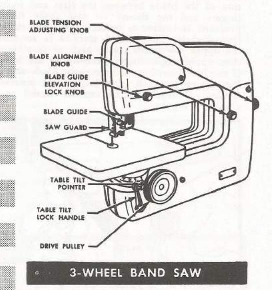
3-WHEEL BAND SAW
2-WHEEL BAND SAW
PRODUCTION TYPE BAND SAW
SELECTING A BAND SAW
There are two basic types of band saws. The first is one which employs two large rubbertired wheels or pulleys, one wheel being vertically mounted on the underside of the saw frame and the other mounted on an upper frame in direct alignment with the lower wheel. It is on these wheels that the band saw blade rides or tracks. On this two-wheel type, the capacity of the saw (width of stock or work which can be sawed when lying flat) is fixed by the diameter of the wheels, since the throat size of the saw is the distance between the forward vertical cutting section of the saw blade and the protective covering which incloses the rear vertical section of the blade. The capacity of the saw, therefore, is a fraction of an inch less than the diameter of the two wheels. The depth of cut which any hand saw will make is roughly indicated by the distance between the table of the saw and the bottom edge of the upper wheel
anc
All work which can be done on the two-wheel type can also be accomplished on the second type of band saw which employs three tracking wheels instead of two. This type has the advantage of providing a deep throat (which enables wide stock to be sawed), but at the same time using wheels of small diameter. The threewheel type band saw is more compactly constructed and does not require the large and somewhat more costly frame or the headroom that the two-wheel type requires to achieve adequate capacity.
RIP FENCE
Available only on some rwowheel saws. Greatly simplifies straight cutting operations. Used for ripping, resawing, and cutting stock to length. Eliminates freehand guiding speeds up sawing operations.
-011)
remains crossenting in one encire motion. Gives a perfectly square cut. Adjustable to any angle — 13°, 21°, 45°, stc., for making accurate mitter cuts. Eliminates layout or guide marks.
TOOL LIGHT
Adjustable position light always provides ample illumination for close, precise cutting. Fits on tool bench or table edge.
accessories for the band saw
The use of various band saw accessories — the miter gage, the fence, and the miter gage stop rod — will make many straight cutting operations much easier. Stock can be quickly cut to any angle with a miter gage. Perfectly straight cuts can be made with the use of the fence. The fence can be quickly adjusted so that stock can be ripped to any desired width. Pieces of identical length can be cut in a few moments with a stop rod. You can easily improvise these accessories for your particular saw, or for some saws, obtain them ready for use.
TOOL BENCHES
Solid, all-steel benches for mounting saw and motor. Sizes 30x16¼ and 18x16¼ inches — just the right height for best work. Can be equipped with casters.

SPEED AND POWER
The electric motor used to power the band saw should rotate at 1725 rpm and be of the constant speed type. A 1/3 hp motor is usually quite adequate for most band saws of nominal size, although the larger models may require a motor of 1 hp size or larger. The surface feet per minute of a band saw blade, for general wood cutting, should be between 1400 and 2500. Proper speed is obtained by the use of different size pulleys.
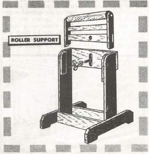
MOUNTING AND LOCATION
The band saw, unlike the larger type circular saws, requires a comparatively small floor space. It can be conveniently located against a wall alongside the workbench. Since the work is fed through the saw from one side (the left side), it is only necessary that free working space be left on each side of the saw.
The band saw should be mounted on a solid, well-made table. A substantial table can be constructed like that shown in the illustration. For a man of average height, the table should be approximately 42 inches high. All four table legs should set firmly on the floor. In some instances, the band saw can be mounted on one end of the workbench; however, such mounting has the disadvantage of fixing the saw to one spot in the shop.

preliminary adjustments

REMOVING THE BLADE Using the Stop Block
Removal of the band saw blade is an easy and quick operation. Take out the table pin or setscrew located at the end of the table slot. Then remove the table insert. Remove the wheel side covers (or single cover) by taking off the knobtype nuts which secure them in place. Release the tension on the blade by turning the bladetension adjustment knob counterclockwise. Lift the blade off of the band saw wheels and slip it through the slot in the saw table.
INSTALLING THE BLADE
Installation of the band saw blade is just the reverse of its removal. Before installing a new blade make sure that it is sharp and in good condition. Also, wipe off any oil or rust preventive coating which may be on the blade. The teeth of the blade must point downward. It is best practice to back out the guide pins since tracking of the blade will thus be facilitated. After the blade has
been mounted on the bade has been mounted on the band saw wheels, reinsert the table insert and the table alignment pins or screws; lightly tap pin in place. Several adjustments must now be made. Proper adjustments will result in long life and superior sawing.
TRACKING THE BLADE
Increase the tension on the blade, enough to hold the blade lightly on the wheels, by turning the blade-tension adjustment knob clockwise. Then manually rotate the wheels and note whether or not the blade tracks properly (it should ride on the center of each wheel-tire). If, when rotating the wheels it is found that the blade tends to ride towards the edge of the tires, the upper wheel of


2-WHEEL BAND SAW
the band saw must be pivoted slightly by turning the wheel-alignment knob. (On the threewheel model, pivot the back wheel to obtain proper blade tracking.)
preliminary adjustments (cont'd)
ADJUSTING BLADE TENSION
The blade tension must be correctly adjusted. Excessive blade tension will result in blade breakage. Too light tension will result in sloppy and difficult sawing. Proper blade tension is obtained by moving one wheel farther

away from the other(s) by means of the tension adjustment knob.
Adjustment of blade tension on those band saws which are equipped with a calibrated adjustment scale is a simple matter. Knowing the exact width of the blade, turn the tension-adjustment knob so that the scalepointer points to the proper scale line.
On band saws which do not have tension scale, adjustment of blade tension is somewhat a matter of experience. On such band saws there are two general methods of determining proper blade tension, these methods being particularly suited to adjusting blades of less than

1/2-inch width. One method is to grasp a section of the blade between the first and fourth fingers and the thumb — and apply thumb pressure. If tension is correct, the blade should flex slightly. The second method is to move the upper saw guide up as high as possible then apply slight finger pressure to the blade. If the blade tension is correct, the blade should flex about 1/8-inch from its natural position. Blades of larger widths can be flexed to a a greater degree.

ADJUSTING BLADE GUIDES
After the correct blade tension has been obtained, the upper and lower guides must be adjusted. Set the guide pins as near as possible to the blade; however, do not let the pins actually touch the blade. The purpose of the guides is to prevent the blade from twisting; but, if the pins are set so closely to the blade that the blade will ride against them, blade life will be shortened.
A simple and accurate method of adjusting the guide pins is to insert several strips of paper between the pins and the blade and then adjust the pins so that they just seat on the paper. When the paper is removed, the necessary clearance will remain between the blade and the pins. While adjusting the guide pins, care must be taken to prevent any of the pins from pushing the blade to one side.

Now bring the bracket which mounts the guide pins, for-
ward so that the forward edge of each pin is just behind the gullets of the blade teeth. If the pins are set forward too much, the saw teeth will be worn or damaged. If the pins are set back too far, the blade will be inadequately guided.
After the guide pins have been properly adjusted, adjust the upper and lower guide-thrust support wheels. Bring the support wheels forward towards the back of the blade so that approximately 1/64-inch remains between the blade and the face of the wheel. The only time the blade should touch the support wheel is when work is being fed into the saw blade. If the blade is permitted to ride on the support wheels at all times, case hardening of the blade will occur and the blade will be likely to break.
SAW TABLE ADJUSTMENTS
To insure square cutting of stock, the zero position of the table must be checked — and adjusted if necessary. Move the saw table to its level position. Then, by using an accurate square placed be-

tween the blade and the top of the table until it is exactly at right angles to the blade. Loosen the screw which holds the table-tilt pointer in place, set the pointer exactly to the zero mark on the adjustment scale, and then resecure it by tightening the pointer screw.
To make it easy to return the table from a tilted position to an exact level position without having to use the calibrated scale, most band saws are provided with a zero-leveling stop-pin or screw. Adjust this stop-pin so that, when returning the table to its level position, it will stop or seat on the stop-pin at exactly its level or zero degree position. Then make sure that the stop pin is locked securely in place.

how to operate a band saw
GENERAL INFORMATION
With a little experience, and by following a few simple operational rules, home craftsmen can quickly acquire the knack of turning out first class work. There is little danger involved in the use of the band saw, but a few safety precautions should be followed.
Before using the saw make sure that it is in good operating condition, and that all adjustments have been correctly made. The saw table and the floor space around the saw should be kept free of pieces of wood and other objects. Onlookers should not be allowed to stand on the right-hand side of the saw, since a breakage of the saw blade might possibly result in their being injured. The cutting area should be well illuminated. Before feeding work into the saw blade, the upper guide and guard should always be adjusted so that it is within 1/4-inch of the work.
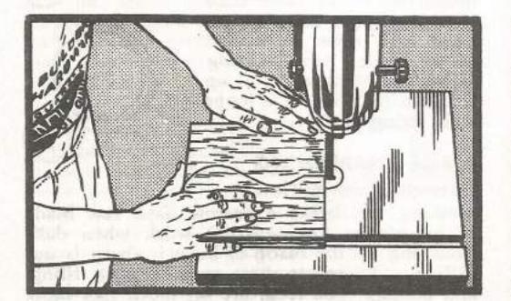
CORRECT PROCEDURE
To operate the band saw, stand on the lefthand side of the saw and assume a natural position. Use your right hand to feed the work into the saw blade and your left hand to guide the work. Never shove the work into the saw feed it forward with even, gentle pressure. If it is necessary to force the work into the saw, the saw blade is dull and should be resharpened. Your left hand should guide the work lightly, and should be kept a safe distance from the saw blade at all times. Avoid clutching the work tightly with the guide hand as this will result in clumsy handling and poor quality sawing.
Before starting the saw, place the work next to the blade and adjust the upper guide so that it is approximately 1/4-inch above the work. After turning the saw on, do not feed the work into the saw until the saw is moving at full speed. Avoid, as much as possible, having to remove the work from the saw by backing up from the saw blade through the saw cut. If this is necessary, move the work away from the blade by keeping the blade parallel to the saw cut.

OVERCOMING LEAD
When feeding the work straight into the blade, the saw should cut a straight line — it should not be necessary to feed the work at an angle in order to saw a straight line. If the saw tends to cut to one side — that is, to "lead" — either the blade guides are improperly adjusted or the saw blade is improperly sharpened. If guides are properly set, it can be assumed that the lead is caused by an improper condition of the saw blade. Lead, due to the saw blade having teeth slightly sharper on one side or unequally set, can often be easily remedied by gently holding a fine honing stone against that side of the moving blade on which the lead is occurring. (The sharper teeth naturally tend to cut faster than those that are dull. Thus, by honing the sharper teeth, the cuting power of all teeth is equalized and lead is eliminated.)

band saw blades
TYPES OF BLADES
The availability of many types of band saw blades greatly increases the utility of the band saw. Although a single blade for general allaround work can be used with good results, there is a right blade for every specific type of work. If the highest quality results are desired, a blade for the specific work operation should be used. Blades can be divided into two main classes: those used for wood cutting operations and those for metal, plastic, etc. (For data on metal cutting type blades refer to the section of this book dealing with metal cutting operations.) Important blade characteristics are: width, number of teeth per inch, and set of teeth.
CHOOSING PROPER BLADE WIDTH
The most significant saw blade characteristic. and one which usually determines what saw blade is to be used, is the width dimension of the blade. Selection of the proper width blade enables the band saw user to turn out good work of jig saw nature, or to do an equally good job of sawing heavy planks into thinner For delicate jig saw type work which embodies sharp or acute curves, blades of the very narrowest widths are used. The kerf or saw cut made by the blade of narrow width is also proportionally narrower since the set of the saw teeth is usually less. One disadvantage of a narrow saw blade, however, is that it will not readily saw along a straight line. There is not enough width for the sides of the blade to act as guides. A wide blade, after once entering the work, causes the kerf to track on the blade. This feature of the wide blade also indicates its shortcoming — it will not make a sharpcurved cut
Thus, in selecting the width of blade to be used for a particular job, follow these points: (1) Choose one which will permit the cutting of the sharpest curves you will need to cut. Refer to the size selection guide shown on page. (2) However, use the widest (not the narrowest) blade that will do your job. (3) For work on which only straight cuts will be made, use your widest blade.

MINIMUM CUTTING CIRCLES
CHOOSING PROPER NUMBER OF TEETH
Since rough work is normally done with large width blades, the larger blades generally are coarser toothed — that is, they have a smaller number of teeth per inch. Conversely, narrow blades are generally finer toothed. Fine-tooth blades make smoother finish cuts, but do not cut quite as rapidly as the coarser type.
Narrow blades with coarser teeth, and wide blades with finer teeth can be obtained, however. For doing a large amount of sawing rapidly, when it is not necessary to make a very smooth cut, blades having coarser teeth should be used. A little experience will soon indicate your particular requirements.
CHOOSING PROPER BLADE TOOTH SET
Generally, you need not be concerned about the set of band saw teeth, unless you are going to sharpen the blade. The set provides clearance for the non-cutting portion of the blade. On 1/4-inch width blades, the set is usually about .005-inch. For each larger size blade it is about .001-inch greater. The greater the set, the greater the width of the saw kerf.
CHOOSING PROPER BLADE THICKNESS
For the most part, the thickness of the blade can be ignored by the average band saw user. Usually, the thickness of a band saw blade is proportional to the size or capacity of the band saw upon which it is going to be used. In other words, thickness depends upon length of the blade.
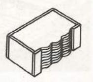
FOLDING THE BLADE
When not in use, wipe blades with an oily rag and fold them for storage. To fold: grasp blade with back toward you - left hand with thumb up and right hand with thumb down, Hold firmly, Now simultaneously rotate left wrist to move thumb down and right wrist to move thumb up - at same time allowing hands to move toward each other as pulled by the blade. Keep twisting wrists and blade will coil up into a triple loop. Tie loops with string or tape.

BLADE SHARPENING General Information
Nothing will break a narrow band saw blade as quickly as forcing it to work when dull. Touching up the blade to keep it sharp is not difficult. There are three steps: setting, filing, and honing. The teeth are set much like those
of other saws and are filed to proper shape and sharpness. Honing knocks the burrs left by filing from the teeth, and helps the blade to run true in the work.
Filing
NOTE: If teeth are to be set, set them before (not after) filing.
Blades from 1/8- to 3/4-inch wide are commonly considered to be narrow blades. Blade thickness varies according to the quality of the steel; but generally averages .001-inch for each inch diameter of the wheels on which blade is intended to run. Narrow blades have from four to seven teeth per inch (five to eight points see sketch) depending upon work for which each is intended. Use a fine smooth-cutting mill file of a size small enough to fit down into the gullets between the teeth. The finer tooth blades require about a 4-inch file, while an 8-inch file can be used on the coarser tooth blades.

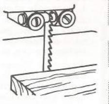
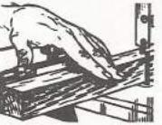
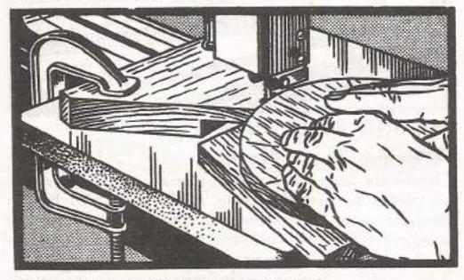
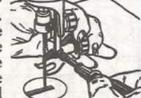
Filing can be done in an ordinary bench vise holding two boards, about 10 inches wide, between which the blade is held. A better arrangement, however, is shown at the top of this page. The wheels which hold the blade are adjustable on the supporting board so that the blade can be stretched taut.
Clamp a section of blade into the vise with about one-half the blade projecting up. File one tooth at a time. File straight across the blade, without allowing the file to dip or turn to either side Maintain original tooth patterns as nearly as possible. Teeth are hooked from 8° to 15°, depending upon style of blade and number of teeth per inch. Gullets must be carefully rounded — any angles or corners in the gullets will cause blade to crack in use. (On coarser teeth it may benecessary to use a rattail file in gullets.) File only on the push strokes, lifting file for return strokes, and try to give same number of strokes to each tooth Work around blade, resetting it in vise, until finished. If teeth are badly worn, set a pair of outside calipers to check heights of teeth points above back of blade, check all teeth, and refile
any which are too high. Occasional touch-up filing can be done with blade mounted in band saw. This method works even better if blade is reversed so that teeth point upward.
Setting
Setting is the bending of teeth outward, alternately in opposite directions so that blade cuts its own clearance. Only the tooth points are bent — never bend teeth more
than half-way down. All teeth should be bent on the same line — a line parallel to back edge of blade.
A number of special tools are made for setting band saw blades; but the occasional worker can use an ordinary hand set. Teeth should be set so that from one-third to one-half the cutting edge of each tooth extends outward from the side of the blade.
Honing
Mount the blade and operate the band saw. Touch each side of the blade very, very lightly with a fine oilstone — just enough so that all teeth will have been touched on each side. Test blade by cutting a piece of wood. If it tends to run to one side, again touch stone to it — on side to which it tends to run — to correct this tendency.
Stopping Cracks
If a crack does not extend across more than one-sixth the width of the blade, it can be stopped by drilling a small (about No. 60 drill) hole at bottom of crack, as shown. Crescentshaped punch marks on each side of blade instead of a hole — will sometimes work.
If blade is less than 1/4-inch wide, it should be broken and rebrazed. Broken blades can be mended either by brazing or silver-soldering; but this generally a job for the expert workman.

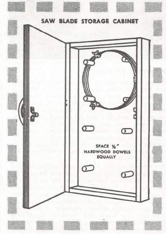
STORAGE OF BLADES
Band saw blades which are not in use should be wiped lightly with an oily cloth to prevent rusting. After being folded they can be stored in an easily constructed cabinet such as that illustrated.

POINTERS TO FOLLOW
Before beginning sawing operations, select and use the saw blade which will do the best job. If the work is of a general nature, however, it may be better to simply use a good allaround blade — one which will permit making varied cuts and do a fair all-around job. Often, very sharp cuts can be made with a blade of some width by making preliminary auxiliary cuts, as will be described in the following paragraphs. If the sawing to be done consists mainly of a number of sharp curves, by all means use a narrow blade.
Always use a little forethought before actually making the cut — useless work will be avoided. After laying out the work on the stock to be cut, decide beforehand at what point the cut should be started. If this is not done, you may often find yourself in the middle of a long cut with not enough throat clearance to finish the cut—and the work will have to be slowly backed out. By beginning the cut at exactly the right point, often the cut can be done in one single operation. Time will be saved.
common saw operations
MAKING AUXILIARY CUTS
Radial Cuts
If it is found necessary to make a few fairly sharp cuts with a wide blade, this can be accomplished by making a number of radial cuts through the waste stock up to the line to be finally cut. The radial kerfs will permit sharp curves to be cut in one uninterrupted operation and without undue twisting of the saw blade. As the finished cut is made, the waste pieces of stock will drop away leaving ample clearance for the blade.

Tangent Cuts
Another method of producing sharp turns without putting too much strain on the blade is that of making a series of tangent cuts. This method may sometimes prove useful; but, ordinarily, the use of radial cuts is more advisable. Sawing a curve by means of tangent cuts requires that a series of interrupted cuts be made rather than one smooth continuous cut — the result tends to be somewhat rough.


MAKING MULTIPLE CUTS
Whenever work requires the making of several cuts, always make the shorter ones first. This will often eliminate the necessity of having to back the work out through a long kerf. With the short cuts made first, the large pieces of waste stock will be freed at the ends of the long cuts.
SAWING NARROW SLOTS
Shown in the adjacent illustration are the steps involved in sawing out long narrow slots. Part "a" of the drawing shows the layout of the slot. In part "b", a single side cut is made and the work is backed out through the kerf. Then the opposite side cut is made and terminated by surving over into the end of the first cut. In part "c", the small remaining corner is removed by making a series of small cuts.


SAWING RECTANGULAR OPENINGS
A rectangular opening can be sawed in a manner like that indicated, in the adjoining illustration. Make one side cut and back the work out through the kerf. Then make the other side cut, back out slightly, cut over to the inside line,
and continue the cut over to the corner of the first cut. Cut out the remaining corner. Often, sharp cuts can be made by first drilling
corner holes in the stock, and then making one continuous saw cut.

MAKING COMBINATION CUTS
Combination cutting — that is, sawing out work which consists of a number of lines that adjoin each other to form sharp corners — must be done by making a series of cuts. Before sawing a combination pattern decide which cuts are to be made first — every pattern has its own peculiarities. However, always make the shorter cuts first.
When the pattern to be cut is of a complex nature, such as that illustrated, a preliminary rough cut should be made first. In rough cutting, the contour should be followed as much as possible but no attempt should be made to do the detailed or fine cutting. After the rough cut is made, the unwanted area of remaining stock can thus be removed by a series of individual cuts.

straight cutting operations
CROSSCUTTING
With Fence and Miter Gage
Crosscutting with the band saw is a standard operation. The depth of cut can be far greater than is possible on the circular saw. Crosscutting operations are facilitated by the combined use of the fence and miter gage.
Use of the miter gage permits the work to be fed into the blade at right angles, or at any other angle. The fence provides a ready means for cutting the work off to the exact desired length. In contrast to the circular saw, the fence can be used as a stop since the work will not bind or kick back.
For best crosscutting results several points should be kept in mind. As in all straight cutting operations, it is preferable to use a wide saw blade. The blade should be sharp and properly set. There must not be any tendency for the work to lead, since, in using the miter gage, there is no way of correcting such a tendency to stray from the straight line.
Using the Stop Rod
If the band saw is not equipped with a fence or, if for some reason, the use of a fence is not desirable, work
can be cut to exactly the required length by using the stop rod, as shown. Generally, it is best that the stop rod be used on the outer end of the miter gage because this eliminates any possibility of feeding the rod into the blade.
USING THE STOP BLOCK
Often you will want to cut a number of pieces to an exact identical length. If your saw is not equipped with a fence, this can easily be done by clamping a block or strip of wood to the left-hand side of the saw table at the desired distance from the saw blade. Work can then be located against block on each successive cut.


Crosscutting Wide Stock
If a circular saw is not available, satisfactory crosscutting of wide stock can be accomplished by turning the miter gage around so that the forward edge of the work can be located against the face of the gage, as illustrated. To obtain better results in this type of operation, secure a strip of wood (which is well squared) to the face of the miter gage. This auxiliary face strip will provide a large surface on which the work can be located and held in place.
Generally, an auxiliary face strip which terminates at the line of the saw blade will be adequate. However, the face strip can extend all the way to the inner edge of the saw table but, in this case, should be of somewhat greater width so as to compensate for the successive, unavoidable cutting of the face of the strip. The strip cannot be much higher than the miter gage since it must clear the saw guide.
Crosscutting With Fence Only
If the miter gage is not available, satisfactory crosscutting can be accomplished by using a wide, well-squared backing board as a substitute miter gage. Simply hold one end of the backing board firmly against the fence and push forward to feed the work into the saw. Crosscutting at various miter angles can easily be done by using backing boards each having the end cut to a desired miter angle.


Freehand Crosscutting
A good method of crosscutting square pieces of stock freehand is to rotate or pivot the stock into the blade. A line drawn or scribed laterally across the saw table just in front of the blade will facilitate all freehand operations.

RIPPING AND RESAWING Using the Fence
Ripping and resawing operations can best be accomplished by the use of a fence. The fence can be rapidly and accurately adjusted so that cutting can be done exactly to the desired width. Always hold the work firmly against the fence with the left hand. As in crosscuting operations, a wide sharp blade should be used and, since there is no way of correcting lead, the set of the blade should be correct. When ending

the cut, care must be taken to avoid running your fingers into the blade. Do not attempt to feed the end of the work past the blade with your fingers. To complete the cut, either grasp the stock in back of the blade or use a push stick.

Before resawing a board of wide width, it is helpful to first make a preliminary guide cut in each edge of the board with a circular saw — the resulting kerfs will then track on the band saw blade.

Working Without a Fence
If a fence is not available, work can be ripped by using the left hand as a pivot point or guide for the work. This simple method of ripping has the advantage of permitting the work to be pivoted in the event that lead is encountered. When freehand ripping is done, it is helpful to first mark the line to be cut with a pencil.
The resawing operation without a fence is facilitated by the use of a pivot block. The block is clamped on the right-hand side of the table and adjusted so that the stock will be cut to the desired width. As with the fence, use the left hand to hold the work firmly against the face of the pivot block. As in freehand ripping, the use of the pivot block permits the work to be fed so as to compensate for any lead.
A simple setup for sawing without a fence, and which can be used to do both ripping and resawing, is shown in the adjacent illustration.

straight cutting operations (cont'd)


To hold the work firmly against the fence block, a spring block is clamped to the inner side of the table so that the mitered
end of the block is opposite the side of the blade. It is so positioned that the work will be wedged against it. As shown, the spring consists simply of a hardwood block the mitered end of which contains a number of equally spaced kerfs.

Ripping Arcs
With a little experience a good job of ripping curved stock can be done. Move the fence over to the blade and scribe a line on it in alignment with the blade. Then position the fence so that the work will be cut to the desired width. Feed the work into the saw blade by keeping it in contact with the fence at exactly the point at which the line is drawn.


Bevel Ripping
When ripping work with the saw table tilted, keep the fence on the right-hand side of the table so that it will support the work. Clearance between the underside of the fence and the saw table will permit the cutting of bevels up to 45 degrees without having the blade graze the fence.
Extensive Ripping Operations
If a great deal of ripping is to be done, it is well to use a blade with characteristics specifically suited for ripping operations. Blade teeth should be coarse and have a large degree of set. For ripping softwoods, the hook of the blade should be between 25° and 30°; for hardwoods the hook should be between 20° and 25°.
HANDLING LONG WORK
Do not leave a long board unsupported so that the spring of the board causes it to shift on the table while sawing. Use some sort of support to catch end of board behind blade; and, if board is very long, use another support in front of saw (in which case board can be pulled through after you have advanced up to the front support). A good homemade support is illustrated. Ordinary wooden horses of proper height will also do; and the drill press table makes an excellent adjustable height support.
compound sawing

NUMEROUS APPLICATIONS
Many types of woodworking projects require compound sawing. Such work includes the curved or cabriole leg, and various outdoor wood ornamentations such as posts and end railings. Compound sawing is also often done preliminary to many standard lathe operations. Since many compound sawing operations require the cutting of wood four or six inches thick, the band saw is the only type of woodworking tool which will accommodate work of this nature.
The cabriole leg is a typical example of the type of work which is made possible by compound sawing. As can be observed by looking at the illustration of the cabriole leg, compound cutting is the cutting of profiles on the two adjoining bases or sides of square-shaped stock. The proper procedures for compound cutting are explained in the following paragraphs.

THE CABRIOLE LEG
General Information
The cabriole style leg is frequently used on chairs and tables. Usually, this type of leg has a square top which permits its attachment to the table top or chair seat. The top curves out into a "knee" which then extends down and inward, terminating in a "foot". The easiest way of making a cabriole leg is to use a single large piece of stock. However, since fine hardwoods are expensive, it is often more economical to make use of "post blocking" — the process of gluing small blocks of wood to an undersize base block at points at which the knee, foot, and other protruding portions are to be formed.

Post Blocking
The first step in post blocking is the selection of stock to be used. Choose big enough pieces to provide ample layout surfaces. Also select pieces which will match in color and grain. All stock should be trued so that each is completely square. Then the small blocks should be carefully and tightly glued to the base piece. If the pieces are properly joined together it will be almost impossible to tell that the finished work is not one solid piece. If the leg is to have ears it is advisable 'to saw them independently from the main section of the leg. They can be joined after the leg sawing operations are completed.

Pattern Layout
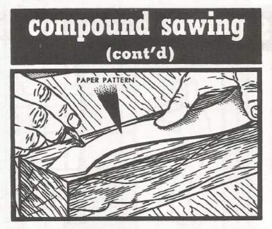
With the stock completely trued up, use cardboard patterns to draw the desired profiles on two adjoining sides of the stock. (Various other methods of transferring patterns to the stock are discussed in the "Jig Saw" section of this book.) If possible, center the pattern on the stock so that the waste stock will be cut off in one piece — this will make later operations easier. The two profile patterns do not have to be laid out with a common center line.
Cutting Operations
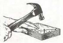
Make the two saw cuts which will form one profile. Try to make each cut in one uninterrupted operation, leaving the waste stock in two pieces. In fact, if possible, leave the waste stock in one piece — and still attached to the main stock - by ending each cut about 1/4-inch from the end of the work, and by then backing the To provide a working surface and the original profile lines for the second or remaining profile to be cut, the waste stock of the first cuts must be nailed back into place (unless left attached as suggested above). When nailing, take care not to drive the nails into that portion of the stock which will become the finished leg. If the original cutting was terminated just before reaching the end of the stock, nailing of the waste stock back into place will not be necessary. Now make the remaining profile cuts all the way to completion. Remove the waste stock which has been nailed in place. Glue the ears


in place. Hand tools can be used to put the finishing touches on the leg.
COMBINATION BAND SAW AND LATHE OPERATIONS
Sawing Speeds Lathe Work
Preliminary band sawing of spherical shaped work will considerably simplify later lathe turning operations. Removal of the waste or excessive stock can be quickly done on the band saw. Band sawing will also outline the finished contours or profile of the work so as to provide an excellent guide for the turning operations.
Band Sawing a Ball
The sawing of a ball is typical of this type of work. First, carefully square the stock to be used. This squaring operation can be quickly accomplished by the use of a jointer. Using cardboard patterns, carefully lay out the profile of the ball on two adjoining sides of the stock. When laying out the pattern, make sure that the center lines on the adjoining faces are lined up perfectly. In addition to the laying out of the ball profiles, also outline, on two ends of the stock, stubs which will permit the work to be mounted in the lathe.
Now perform the compound band sawing operation in the manner already explained. Use a narrow blade for this purpose.

miscellaneous operations
CUTTING CIRCLES Freehand Method
Like any other type of curved cutting, a circle can be laid out on the stock with a compass and then be cut out freehand on the band saw. However, unless you are unusually skilled, the freehand sawed circle will be somewhat uneven and will probably require further reworking.
Circle Jigs
Perfect circle cutting can be done easily and rapidly by means of a circle jig. Most circle jigs are simple in construction. Once the jig has been set up, a number of circles can be turned out very quickly. A feature which is common to all circle jigs is a pivot point — the

circle jig being merely a device which provides a pivot point on which the stock can be located. An easily constructed lig consists of a rectangular piece of plywood which is edged with two wood strips, as shown. The strips permit the plywood to be clamped to the right-hand side pivot point is mounted at the center of the plywood so that it will be in lateral alignment with the front edge of the saw blade. The pivot can either be a nail, or a dowel-screw, one end of which has been filed down to a point. The desired diameter of the disc or circle to be cut is obtained by positioning the plywood on the saw table so that the distance between the blade and the pivot will be equal to the radius of the disc.

When setting up a circle jig, there is one con dition that is very important: the pivot point of the jig must be exactly in lateral alignment with the forward cutting edge of the blade — that is, the pivot point must be located on a line which is perpendicular to the side of the blade at the tips of the teeth. If the pivot point is not accurately located, it will be impossible to cut the circle. Even an error of 1/8-inch in pivot point position will cause improper cutting If the pivot point is somewhat behind the blade. the blade will cut or track outside the circle. If the point is in front of the blade, the blade will pull to the inside of the circle. No matter what type of circle jig is employed, the pivot point must be properly located. When

using some types of circle jigs, it may be necessary to correct a slight error in pivot point location by relocating the blade to one side or the other of the band saw wheels.
An excellent type jig — one which can be quickly set up — is shown in the accompanying illustration. For this type of jig, the right-hand blade guide must be removed and replaced with a substitute guide in which two top studs have been inserted. Keyway stock can be conveniently used for this purpose. The basic part of the jig consists of a hardwood arm, one end of which contains two drilled holes which permit the arm to be slipped onto the two guide studs and then rigidly secured by wing nuts and washers. Along the length of the arm are a series of equally spaced holes in which a pivot can be

miscellaneous operations (cont'd)
inserted. A circle of any diameter (corresponding to the spacings of the arm holes) can thus be cut. The pivot point stud can be secured in a hole with a square nut and a wing nut. Instead of a series of arm holes, you can also use a continuous slot which has been calibrated.
Another type of circle jig employs an auxiliary table. This table should overlap the edges of the actual saw table so that wood strips can be secured to the underside of the auxiliary table around the edges. These strips will hold the auxiliary table in place on the saw table. The auxiliary table is slotted on a line drawn perpendicular to the saw blade, and a sliding piece — which incorporates a pivot point — is arranged in the slot. Circles of various diameters can be cut by positioning the pivot slide in the table groove. To prevent the slide from coming out of the slot, the slot can be dove-tailed and the sides of the slide beveled.

Circles of very large diameter can be cut on the band saw by using a pivot point which is mounted on a support that is completely separate from the saw, such as a small table. The principal requirement of this type set-up is that the pivot point mounting be absolutely stationary. Also, great care must be used in positioning the pivot point, as already explained.

MULTIPLE SAWING How and When Used
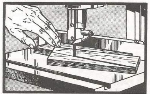
When a number of identical pieces are to be cut out, much time can be saved by sawing several at one time — that is, sawing them "in multi-
ple". In general, this process consists of securing together, by some means, a number of pieces of stock which have been stacked on top of each other. The outline of the cut to be made is drawn on the top piece, and then all of the pieces are cut out simultaneously. Afterwards, the pieces must be separated. Since they are all cut at one time, all will be alike.
Securing Stock Together
The important thing to know about multiple sawing is the various ways by which the pieces of stock can be secured together. The simplest method, of course, is to nail them together at points which will cut away and become waste stock.
Another method of holding stock together utilizes a spring block. A spring block is simply a wood block in which an opening or channel has been cut. The width of the channel must be slightly less than the width of the stock to be held. After the pieces of stock have been sawed, they can be readily removed from the block. A disadvantage of the spring block is that the pieces of stock which are used must all have the same width so that they will be equally accommodated by the block channel and all will be held tightly.
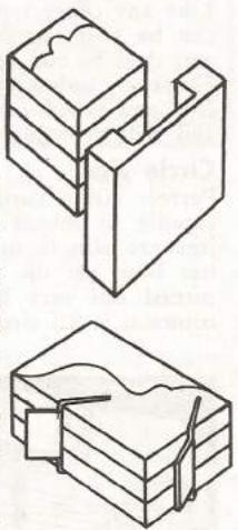
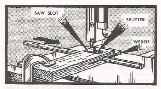
When the pieces of stock have a large waste area they can be held together by wedges. The pieces of stock are stacked together and then two or three kerfs are made in the edges of the pieces — preferably on different sides. A wedge is then inserted in each of the kerfs to secure the pieces tightly together.
If a large number of pieces are to be cut, the box jig will prove useful. This jig is merely a box which will hold several pieces of stock without their being wedged in any way. After the pieces are cut, they can be quickly dumped out of the box. Instead of marking the outline

of the cut on the top piece of stock, a template can be laid on top of the top piece of stock. Or, instead of using a separate template with the box-type jig, the top of the box can be employed as a template. In this case, the top of the box is cut to the pattern before the stock pieces are put into the box.
RIPPING IDENTICAL PIECES
Another way of cutting out a number of identical pieces is to saw out the desired shape from stock of considerable thickness. This piece can then be turned on one edge and ripped into a number of identical thinner pieces.
SAWING WITH PATTERN GUIDES
The cutting of a number of duplicate pieces can sometimes be best accomplished by the use of a pattern guide. Only work which has broad curves can be sawed by this method. As shown, a guide arm is clamped to the inner side of the saw table so that one end of the arm is located at the saw blade. An opening on the underside of the arm permits the passage of the waste portion of the stock. The end of the arm is curved so as to mate with the broadest curve of the pattern. A small slot in the end of the arm permits the recessing of the blade so that the outer side of the blade is flush with the end surface of the guide arm.

The stock is secured to the underside of the wood pattern by suitable anchor points. To make the cut, saw through the waste stock so as to locate the edge of the pattern firmly against the end of the guide arm. Keeping the side of the pattern squarely against the arm, feed the work around to complete the cut. The pattern must be kept tangent to the end of the arm at all times. This is made easier by marking tangent lines on the face of the pattern. In making the cut there is no danger of cutting too far into the stock.
CUTTING DUPLICATE CURVES
Several types of jigs can be used to cut a number of duplicate curved pieces of work rapidly. One type can be made by cutting the desired curve through the length of a wide board. One of the cut pieces is then clamped to the inner side of the saw table so that the curved side is located next to the saw blade. The other piece is then used as a sliding table. This table is provided with an end stop block and two sets of location pins, as indicated.
The stock to be sawed is located on the sliding table, being properly positioned by two

dowel pins which can be inserted in the location-pin holes so that the proper width of stock is cut. To make the cut, feed the sliding table forward, at the same time tracking it against the curved guide board which is clamped to the table. As each successive piece is cut, move the side location-pins over by the amount cut away from the sliding table. This will give the proper width to the next piece to be cut.

CUTTING PERFECT ARCS
A simple set-up for cutting perfect arcs can be made as shown. This set-up consists of an auxiliary table on which a "T" shaped arm is pivoted. As in the cutting of circles, the pivot point of the "T" must be exactly in line with the cutting edge of the saw blade. The work is cut by securing the stock to the "T", and by then feeding the stock into the blade.

Beveled Curves
Beveled curves can be readily cut by using a jig similar to that illustrated. This type jig consists of a curved fence or guide block and a sliding block. The stock is loaded into the beveled slot
miscellaneous operations (cont'd)

of the wood block and the cut is made by pushing the block forward, while holding it, at the same time, against the curved fence. The curve which is cut will be a duplicate of the fence curvature. The stock is located to the proper depth in the block by the small stock strips fastened to the end of the block.

RIPPING CURVES WITH A GUIDE ARM
Once a curve has been cut on a piece of stock, an identical curve can be cut on the opposite side of the stock by the use of a guide arm. The guide arm is a wood strip having a rounded end. This arm is clamped to one side of the saw table so that the rounded end is a distance from the side of the saw blade which is equal to the width desired for the finished work. To make the second cut, guide the stock by pressing the finished edge against the rounded arm end, turning the stock as needed to keep the finished edge tangent to the arm.

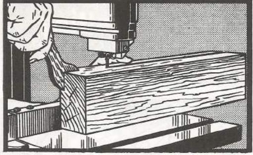
HALVING DOWEL STOCK
A simple device for splitting dowels consists of a block of wood through which a horizontal hole has been drilled. This hole should be the same size as the dowel to be halved. Draw a diameter perpendicular to the bottom of the block at one end of the hole. Now feed the block to the saw cutting on this diameter about halfway into the block - stop the saw, and bolt the block to the table. When dowels are fed through the hole to the blade, they will be neatly halved. To keep dowels from rotating while feeding, place a small metal strip in the block, in back of and in line with the blade so that it will guide the dowel kerf. If a saw cut is made through the end of the block past the hole, the hole can be expanded by a wedge drawing the top and bottom together with a screw - to take care of slight variation in
MAKING TAPER CUTS
A Simple Taper Block
Duplicate taper cuts can be made on a number of pieces by simply using a block in which the desired taper has been cut. The cut is made by loading the work into the taper block and then feeding the block forward along the saw fence. The width of the stock being cut is adjusted by properly locating the saw fence with respect to the blade.
An Adjustable Taper Jig
Shown in the adjacent illustration are the details of an adjustable taper jig. The jig is hinged at one end and adjusted at the other by means of a slotted metal arm. The jig should be at least 24-inches long. To use this jig the two arms of the jig are simply opened so as to obtain the correct angle on the shoulder side when the opposite side is placed squarely against the saw fence. If the jig is opened 1 inch

at a point 1 foot from the hinged end, the taper will be 1 inch per foot, if it is opened 2 inches at a point 1 foot from the hinged end, a 2-inch taper will be formed, etc. In cutting legs which have the same taper on opposite sides, the taper is first cut on one side; then the jig is opened to exactly twice the angle of the first setting and the taper is cut on the opposite side of the leg.
MAKING SPIRAL DOWELS
It is surprisingly easy to cut spirals on dowel stock. Tilt the saw table to about 15° to 20° and position the miter gage near the cutting edge of the saw blade. The depth of the spiral cut is determined by the distance the miter is positioned from the front of the saw blade. Hold the dowel against the face of the gage and start the cut on the end of the dowel. The saw blade will automatically pull the dowel forward and rotate it at the same time. However, the dowel must be held to prevent too rapid cutting.

CROSSCUTTING LONG STOCK
Because of the limited throat clearance of the band saw, the centers of long boards ordinarily cannot be squarely crosscut. However, crosscutting of long stock can be accomplished by grinding about a 25° angle on the blade guides of the upper
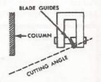
saw guide. Blade guides with a 25° angle will thus turn the saw blade to a 25° angle so that a long board can be squarely crosscut without interference from the vertical back section of the saw frame. Rubbing between the blade and the blade guides will shorten blade life somewhat, but not too great of a degree. A narrow blade should preferably be used. If the blade teeth have a fairly large set, the blade guides
can be lubricated with wax, since the kerf made by saw teeth with a large set will reduce the rubbing action of the blade against the blade guides. The lower guide pins can be completely backed away from the blade, although both roller supports should be used.
Occasional crosscutting of long stock can be done by using an auxiliary wooden saw table. With both the upper and lower guide pins backed away from the saw blade, a saw kerf on the auxiliary table cut at a 25°

angle with respect to the normal alignment of the blade will track the blade at the same angle. Wide boards can be crosscut, using the above methods, by first cutting halfway through the board, backing the board out and flipping it over, and then cutting the other half.
USING A STEP GAGE
A step gage (like the one illustrated) can be used to quickly cut off short pieces of stock to different lengths, such as dowel stock.

CUTTING CIRCULAR RAILS
Shown in the adjacent illustration is an economical method of cutting circular rails. As indicated, the curved cut is first made in a section of board stock. The inside piece of the resulting two pieces is then glued to the straight edge of the outside piece. The inside curve can then be recut to the proper size, if necessary.
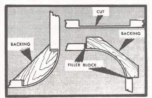
SAWING FACING STRIPS
Facing strips having a corner curve can be made in one continuous piece without having to steam the wood by cutting that section of the strip which is to be the curved corner to about 1/4-inch thickness. Backing blocks can be made as shown. By leaving a small opening at each corner of the block, small wedges can be driven in between the corners of the block and the facing strip, when the facing strip is glued to the block, thus affording a very solid joint.
metal cutting
METAL CUTTING BLADES
General Information
Metal cutting blades differ considerably from those used for wood cutting. They are much finer toothed, hardened and tempered, and have varied types of tooth set. When selecting a blade for a specific metal cutting operation, two blade characteristics must be considered - mainly. the number of teeth per inch and, secondly, the
Choosing Number Of Teeth
When cutting thick stock, at least five or six blade teeth should come into contact with the work at the same time. However, if the blade is too fine-toothed, the clearance will be insufficient and the teeth will clog.
A coarser tooth blade will cut faster. However, on thin stock, such as sheet metal and tubing, the finer toothed blades must be used. The teeth will be stripped off the blade if the blade is so coarse that the teeth straddle the material. When cutting thin stock, at least two teeth must contact the work.

Choosing Correct Tooth Set
Metal cutting blades have three types of set. Those which are similar to wood cutting blades have teeth which are all alternately set to the right and left. This type of blade is used for cutting the softer metals. The second type of blade has teeth which are of a "regular" set. Every third tooth is unset and serves as a raker tooth to clean out the cut. This type of blade is used for cutting such metal as cold rolled steel and cast iron. The third type of blade has teeth which are set in wayes. This type blade is used for cutting thin metal such as that of tubing and pipe.
For general use the blades which have a regular set will give the best results. Although these blades are intended for cut-
ting the harder type metals. they will do a fair job of cutting the softer metals. Blades having every tooth set, although ideal for cutting the softer metals, will not cut
1 - ----------------------------------China and an Alexandra and State
-------
METAL CUTTING SPEEDS
Metal cutting should be done at about 1/6 the speed of wood cutting. If a great deal of metal cutting is to be done, the band saw should either be equipped with back-gearing or a countershaft. Most conventional wood cutting band
saws can easily be equipped with a countershaft. Do not cut metal at wood cutting speeds - it
METAL CUTTING TECHNIQUE
Generally, metal cutting operations are done in the same manner used for wood cutting operations. Both the miter gage and the saw fence are used. The biggest difference between metal cutting and wood cutting is that almost all nonflat metal work should be clamped securely. Metal cutting is somewhat slow and it is impossible to hold such work as tubing in place by hand during the sawing process. "V" blocks, "C" clamps, wood blocks, et cetera, can all be used advantageously to hold down the work. Shown is a simple method of holding down tubing. Here two "V" blocks, bolted together

Also shown is a quick makeshift for holding large-diameter tubing. The clamp prevents the stock from turning, and the wood block braces the work, preventing it from being distorted. This block is held against the fence, which has been positioned so that the stock will be cut off to the proper width.
To prevent thin stock from burring when it is cut, the metal can be supported on the under-
side by a strip of wood. Burring of thin-walled tubing can be avoided by plugging the tubing with dowel stock. As in wood cutting, multiple sawing of metal can be done. The metal stock can be secured together by solder tacking or sweating.


SPRING-LOADED TYPE JIG SAW

A TOOL OF MANY USES
The outstanding feature of the jig saw is its capacity to start inside cuts within the center section of work, without first having to make a preliminary cut through the side of the work. Blades can be inserted in a few seconds through a "start hole" which has been drilled in the work. Use of fine hair-line type blades permits the making of exceedingly intricate cuts.
The availability of many different types of saw blades makes it possible to cut all kinds of materials — wood, metals, plastics, etc. Wide saber type blades permit straight line sawing crosscutting and ripping — although work of this nature is better performed on the circular or band saw. Files of all shapes — round, square, triangular, crochet, etc. — make metalworking easy. With the use of cylindrical type, sanding sleeve holders, fine curved work can be quickly sanded.
SELECTING A JIG SAW
A good jig saw should be sturdily constructed and free of excessive vibration to stand up over a long period of time. In addition to these basic considerations, the jig saw should be selected according to its capacity and various refinements.
The capacity of any jig saw, like any band saw, is indicated by the distance between the saw blade and the rear vertical section of the frame. A jig saw with an 18-inch throat capacity will cut to the center of work 36 inches wide. The

Gives superbly smooth operation free of vibration. Evenly distributes power to both ends of blade. Eliminates sudden loading of power system on successive strokes. No concentrated wear.

Available for sawing all type: of materials — wood, metals plastics, etc. Sizes range from a fine, hair-line to heavy sabe

Make final finishing easy. Will mount in lower chuck of some jig saws. Variety of shapes — round, triangular, crochet, etc. — permits working profiles of any shape.
GRINDING TOOLS
Enable you to grind internal openings in metal work which would otherwise be inaccessible. Several shapes and sizes are available.
depth of cut which a jig saw can make varies from a fraction of an inch to two inches — on the larger saws.
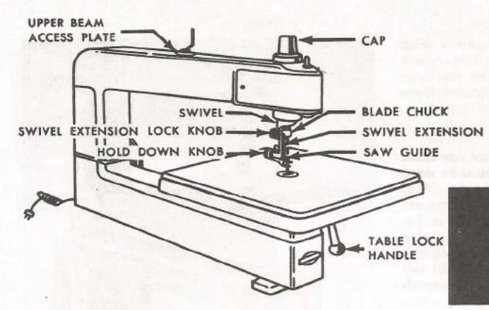
In general, jig saws consist of a frame, a table, upper and lower slide rods or plungers, upper and lower chucks, upper and lower blade guides, an electric motor, and a mechanical system for converting the rotary motion of the electric motor into up-and-down motion.
The down-stroke (cutting stroke) of most jig saw blades is the power stroke; whereas, the up-stroke is produced by a spring located in the upper tube of the saw. This spring is loaded or stretched out on the downward cutting stroke. The rotary movement of an electric motor is converted into up-and-down or reciprocating motion by means of an eccentric system such as a crankshaft.
Instead of using a spring to achieve the upstroke of the blade, some jig saws directly apply power to both ends of the blade, on both the up- and down-strokes, by means of a so-called "walking beam". Since the drive system is not subjected to sudden loading on the successive down-strokes, this type of jig saw assures smooth, uniform cutting action which eliminates, to a considerable extent, blade breakage and vibration.
Another type of jig saw — the "magnetic" type — completely does away with an electric motor and complicated drive system; its simplicity of construction affords an exceptional economy. In place of an electric motor, the magnetic jig saw uses a self-contained magnetic power unit which imparts 7200 cutting strokes per minute to the saw blade by means of a diaphragm.
It will cut moderately thick wood as well as thin, soft metals such as copper, aluminum, and brass. It is completely safe to operate, even for a child.
Jig saws incorporate many refinements which greatly add to the ease and convenience with which the saw can be operated. Some house a small lamp in the upper frame, which floods the work with light. In some there is a blower, which sends a stream of air around the cutting section of the blade and keeps the cutting line free of sawdust. Some have a tilting table, which can be adjusted in two directions to any angle up to 45 degrees by means of a calibrated degree scale with pointer. This makes bevel cutting possible. The table of many jig saws
accessories for the jig saw
Most jig saw work does not require the use of any accessories. Sometimes, however, the use of certain accessories will make certain woodworking operations much simpler. If a great deal of metalworking is to be done, you will definitely want a set of metal cutting files. Cylindrical grinding tools and sanding sleeve holders will also prove useful.
can also be rotated 90 degrees — together with the blade chucks — thus permitting large work (which would not otherwise clear the rear vertical section of the saw frame) to be fed from the side of the saw.
SPEED AND POWER
A 1/4 hp, 1725 rpm motor is suitable for most work. However, a 1/3 hp motor should be used if the saw is to be operated continuously. Most jig saws operate at 850 strokes per minute, since the ideal speed for cutting wood is between 800 and 900 rpm. (This speed is also about right for cutting metals.) Higher speeds than this are not necessary since you could not accurately follow the pattern lines if the work were fed more rapidly.
MOUNTING AND LOCATION
The jig saw can be located against one wall of the workshop, and should preferably have at least four feet of unrestricted working space on each side. It should be firmly mounted on a solid, well-constructed table. All legs of the table should set firmly on the floor. Proper mounting of the jig saw will reduce much of the vibration.
IMPORTANCE OF BELT AND PULLEY COVER
The jig saw is by far the safest power tool to operate. However, it is strongly recommended that a protective cover or shield be placed over the motor belt and pulleys to keep them from "grabbing" loose clothing.

BLADE HOLDERS
Very convenient for holding your various jig saw blades. Prevents them from becoming dull or damaged.


Excellent for lengthy operations. Takes the effort out of jig saw work. Easily folded out of the way. Simple to construct.

preliminary adjustments
IMPORTANCE OF ADJUSTMENTS
Before you use the jig saw, all adjustments should be properly made. Correct adjustments will insure optimum results — the jig saw will give better service — and blade breakage will be minimized.
TABLE ADJUSTMENT
On some types, the saw table can be tilted to either side to any angle up to 45 degrees. Degree of table tilt is indicated by a calibrated protractor-type scale and scale pointer. To reposition the

table, release it with the table lock handle, move the table to the desired angle as indicated by the scale pointer, and resecure it with the lock handle.
As a preliminary set-up adjustment, after the jig saw table has been made as level as possible, set the table to an exactly level position by the use of a spirit level. Then loosen the screw securing the table tilt scale pointer in place, set the pointer at precisely zero degrees, and retighten the pointer screw.
INSTALLING THE BLADE
The jig saw blade must be installed in the blade chucks so that it will move in a true vertical line throughout the stroke. Also, it must be correctly tensioned. Slip the lower end of the blade through the table insert (blade teeth must always point downward) and into the lower

chuck. Generally, only the non-toothed end section of the blade should be inserted in the chuck. Tightly clamp the blade in the chuck with the blade clamp setscrew (unless — as on some saws — the blade merely engages in a slot in the chuck). (Some saws have a setscrew for making a blade centering adjustment, refer to "Chuck Adjustment". Normally, this adjustment screw should not be moved after once being properly set.) Turn the saw pulley by hand until the blade is at the top of its upstroke, at the same time guiding it into the upper chuck. Pull the upper plunger down to obtain proper blade tension and securely lock the blade in the chuck.
NOTE
Some saws — principally the magnetic type — do not have chuck clamps. Instead, the blades have broadened or pin ends (of one type or another) which engage in T-slots in the chucks.
The distance which the upper plunger must be pulled down varies with different jig saws. Blade tension should be just enough to hold the blade in a straight line during cutting operations. If the blade tension is incorrect, blade breakage will occur frequently.
Too, if the blade is slack, it will tend to weave from side to side and will not cut true. Tension can be checked by manually bringing the blade down to the bottom of the down-stroke and then releasing it — if it buckles, tension is insufficient.
After the blade has been chucked, determine whether or not it runs in a true vertical line. This can be done by laying a pencil flat on the table so that the point just touches one side of the blade. Move the blade through one complete stroke by manually turning the saw pulley. If the blade is correctly aligned it will neither move away from the pencil point, nor push the pencil to one side as it moves through the stroke. If the blade alignment is incorrect, check to determine whether or not it is correctly centered in both lower and upper chucks.
Installing Fine Blades
Fine jeweler's blades can be quickly aligned and chucked by the use of a squared wood block in which a perfectly straight kerf has been cut.

Simply hold the block firmly on the saw table, as shown, and align the blade by engaging it in the kerf.
ADJUSTING THE CHUCK
If the blade is correctly chucked and still does not run true, it can be realigned — on some jig saws — by readjusting a chuck adjustment screw which is opposite the bottom chuck blade clamp screw. Before attempting to turn the chuck adjustment screw, make sure that the clamp screw has been loosened.
ALIGNING THE SAW FRAME
In the initial set-up adjustments of the jig saw it is sometimes necessary to relocate the upper frame, with respect to the base, in order to make the blade run true. This can usually be done by loosening the nut(s) or screw(s) which secure the upper frame to the base of the jig saw, and by then lightly tapping the upper frame into alignment.
FINAL TABLE ADJUSTMENT
After the blade has been aligned as much as possible, use a square to determine whether or not the blade is perpendicular to the saw blade. If it is not, set the table so that the blade and table are exactly at right angles to each other. Then reset the table-tilt scale pointer to exactly the zero degree mark.
USING BLADES OF EXTRA LENGTH
Some jig saws permit the use of blades of extra length by allowing the blade to extend through the chucks and into the space inside the plunger tubes. When a long blade is used, it should occasionally be repositioned in the chucks by moving it up or down. The cutting will thus be distributed over a greater section of the blade, and the blade will remain sharp for a longer period of time.
ADJUSTING GUIDES
The blade guides support and maintain the blade in a straight line during the cutting process. They must be properly adjusted. Position each guide so that the blade is centered in the guide slot, and the guide just touch-
slot, and the guide just touch es the back edge of the blade. For best results, the guide should be as close as possible to the sides of the blade without binding it, and the front ends of the guide should
be just behind the blade teeth. When saber blades are being used the lower guide alone will often provide enough support for the blade, and the upper guide can be moved out of the way. When using fine jeweler type blades, it will often be found that no guides whatsoever are necessary. However, the guides will provide thrust support to a fine blade.
ADJUSTING HOLDOWN CLAMP
Adjust the holddown clamp so that it just touches the top side of the work. The clamp prevents the work from being lifted up by the up-stroke of the blade. When the table is tilted for a bevel cutting operation, the holddown clamp should be set so that one side of it touches the top

ADJUSTING SPEED
Generally, lower speeds should be used when operation requires the use of fine blades or when hard materials, such as metals, are being cut. When using saber blades, the higher jig saw speeds are permissible.
ROTATING THE CHUCKS AND TABLE
For side cutting it will sometimes be found that large work will not clear the back vertical section of the frame. In this event, it will be necessary to loosen the chucks and rotate them 90 degrees so that work can be fed to the saw from one side. On some saws it is necessary to also rotate the table 90 degrees — if bevel cutting is to be done, the table must be rotated.

LUBRICATION
Before running the jig saw, make sure that it has been properly lubricated and that the crank case is filled with the recommended grade of oil. (Some saws do not require any lubrication.)
REGROOVING GUIDE PINS
After the jig saw has been given considerable usage, it will sometimes be found necessary to reface and regroove the guide pins. If this is necessary, reface the guides with a power grinder or a hand file. Turn the jig saw blade around so that the teeth face

the back side of the saw. Insert the guides in the guide holders so that the refaced ends just touch the teeth of the blade. Turn the saw on and gently push the blade against the guides with a wood block until the desired groove depth is obtained.

PROPER BLADE SELECTION Importance of "Right" Blade
Blades of many sizes and types are available. For best results the "right" blade should be used. There are special type blades for cutting different materials: hard and softwoods, plastics, bone, ivory, and hard and soft metals. Some blades are a fine, hair-line type, others are heavy and rigid. Blades have fret, skip, and hack-saw type teeth.

Two Main Types of Blades
Blades can be classified as either jeweler or saber blades. Those which are used for making fine, intricate cuts, and which must be secured in both the upper and lower saw chucks, are commonly called jeweler blades. Heavy, rigid blades which do not have to be clamped in the upper chuck are commonly called saber blades. Jeweler blades are used for most cutting operations. When the curves are not sharp, or if straight cuts are to be made, it is advantageous to use saber blades. Since saber blades no not have to be clamped in the upper chuck, successive inclosed cuts can be quickly made. When jeweler blades are used, it is necessary to release the blade from the upper chuck each time a different inside cut is executed.
Choosing Proper Size
Always use the widest blade possible. Of course, if very acute curves must be cut, the narrower blades are required. A wide blade does not break easily and does not tend to weave from side to side — its use makes straight cutting much easier. A narrow blade tends to twist and is easily broken, requiring greater care in
how to do most with jig saws
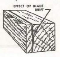
feeding the work. When cutting heavy stock, the narrow blade has a tendency to "drift"; if it is necessary to use a narrow blade when cutting thick stock, feed the work slowly and make sure the blade is fully tensioned.
Choosing Proper Blade Teeth
Jig saw blades have varying numbers of teeth. Usually, the blade is somewhat finer toothed when it is used for hard materials, particularly metals. If thin stock is being cut, a fine-tooth blade should be used. If the teeth are so coarse that they tend to straddle the stock, the blade will tend to tear he material rather than cut it. However, the coarser tooth blade will cut faster and is preferable when heavy stock is being cut.
TRANSFERRING PATTERNS TO WORK
Uses of a Pattern
Good jig saw work calls for careful and accurate transfer of the design pattern to the wood stock. First, if a ready-made pattern is not being used, the desired pattern is usually drawn to full scale on squared paper. It can then be transferred from the paper to the wood stock by one of several methods.
If it is not necessary to preserve the pattern it can be pasted directly to the wood stock. However, use carbon paper for making most actual transfers.
If duplicate pieces are to be made, the first piece can be cut out and then used as a template to directly trace the pattern for successive pieces.

The Perforated Pattern
If a large number of duplicate pieces are to be sawed it will sometimes be best to use a perforated pattern for marking the stock. Transfer the original pattern to stiff

paper, such as heavy construction paper. Then perforate the paper along the pattern lines with a large needle. When the design is intricate the holes must be spaced very closely together. Place the perforated pattern on the stock and pat it with a cloth pad or sponge which has been dipped into a transfer ink. The ink will penetrate the perforations and thereby mark the pattern on the stock. Suitable transfer ink can be made by thinning asphaltum paint with benzine, as required.
The Template
Another method of transferring patterns to the stock utilizes a stencil, or template, made out of stencil board or sheet metal. The stencil is laid on the stock and an ink

or paint is brushed around the edges of the stencil with a small paint brush. The paint thus covers and shows up the waste stock which is to be cut away.
CORRECT OPERATING TECHNIQUES
How to Start Cuts
If an inclosed cut is to be made, drill a hole in the inside waste stock. Slip the stock over the upper end of the blade and make sure the blade is properly chucked. Adjust the holddown clamp so that it just touches the stock. Assume a natural standing or sitting position in front of the saw. Use the left hand to hold the work down in place and the right hand to guide and feed the work. Guide the work by pivoting it as is necessary to follow the pattern line.

Feed the work gently into the blade — do not force feed! Shoving the work into the blade will quickly cause the blade to break. Also, do not twist the blade — if the sharp curves or corner cuts cannot be made by cutting into the waste stock, or by other means, then use a narrower blade. If heavy stock is being cut with a fine blade, feed the work very slowly.
When starting the blade into the stock at an angle, the blade will have a tendency to slip along the side of the stock. This can be avoided by applying light side pressure to the stock.
Cutting Square Corners
Since jig saw blades are usually quite narrow a square corner can be executed in several ways. Often the inside square corner cut can be made by simply leaving a slight round at the corner. When a fine blade is being used, the slight resulting round is often unobjectionable
If not too cumbersome, a corner cut can be made by making a loop-type cut. Simply cut into the waste stock at the corner, then pivot the work all the way around in order to start the second straight cut.
A square corner can also be cut by making a slight jog into the waste stock, as shown. However, after completing the sawing operation, the bulge must be filed or sanded off.
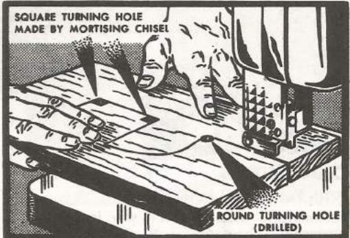
If a number of corners must be cut, making holes with a mortise chisel on a drill press will often prove useful.
Cutting Acute Angles
A clever method of cutting very acute angles is as follows: Start the cut at "S" and continue over to point "Y". Back up the work to point "X" and complete the cut to point "F". Then, back the blade into the "XY" kerf and make the cut from "Y"


to "Z". This method of finishing the corner permits a clean, smooth cut to be made.
Straight Cutting
To facilitate straight cutting operations, such as ripping and crosscutting, a fence should be improvised. This can be simply a wood strip trued on one edge and clamped to the saw table. (Refer to the "Band Saw" section of this book — many band saw cutting techniques are applicable to the jig saw.)


PREPARING INLAYS
Pad Method of Piece Cutting
Inlaying is the process of forming a mosaic design or picture out of many smal pieces of different kinds of wood or other material. Inlay decoration is frequently used on tables, lamps, book ends, cigarette boxes, etc. Independent picture inlays and plaques are very attractive. The most common inlay material used is 1/28-inch veneer. Veneers of many types of fine woods are available - walnut, mahogany, cherry, etc. Moreover, various metals such as bronze, copper, brass, and aluminum — and colored plastics, as well make good inlay materials. The art of making inlavs is not too difficult for the home craftsman: but requires accurate, careful work. After you choose a picture or design. decide how many different used. If the design is simple,
kinds of wood are to be two or three woods will usually afford enough variety. If a picture inlay is being made, however, even a dozen different woods may be used to advantage; but do not overdo it — the proper effect will be lost. The wood colors and grains should be different enough to contrast harmoniously, and the background area should be made to show up the pattern to advantage. Transfer the pattern to one sheet of stock. Assemble the various sheets of veneer into a pad with

miscellaneous operations

the pattern sheet on top, and secure all together with small brads or by other means (refer to page 18, "Multiple Sawing"). Now, saw out the pattern in the usual manner. Since all the different pieces of the pattern are simultaneously cut from each sheet of veneer, any piece of veneer will fit perfectly into the pattern opening for which it is intended.
Select the pieces which are to make up the inlay. Using rubber cement, glue them to a temporary base, such as heavy cardboard. This will enable the pieces to be fitted to-
gether properly and any slight readjustments to be made. Then glue the opposite side of the complete inlay to a heavy, permanent base. After the glue has set firmly, strip off the temporary base from the top.
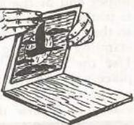
Finishing the Pattern
Sand the inlay with 0 and 00 sandpaper until it is perfectly smooth and all inlay pieces are level with each other. Coat it with a clear varnish or other suitable finish. Avoid a mirror finish as this will ruin the natural contrast of the woods.
Making Veneer Inlay Patches
Sometimes, when making a complex veneer inlay, it will be found more practical and economical to use small pieces of veneer, rather than sheets of equal size assembled into a pad. This is particularly true for those sections of inlay which require only one or two small pieces of a particular wood. Small pieces of veneer are used by inserting them into heavy cardboards which are about the same thickness as the veneer. Do this by cutting the proper openings into the cardboard, and by then securing the pieces of veneer into the openings with gummed tape. The cardboards with veneer patches can then be assembled into a pad for sawing, as already explained.
Bevel Sawing Pattern Pieces
When pieces of wood are to be fitted together, such as an inlay, it is desirable to have them fit snugly with no space between the joint lines. Even though a fine blade is used for pad sawing an inlay, the blade kerf will cause a space or crack to exist between the fitted pieces. This space can be eliminated by making the saw cuts with the saw table tilted from one to about eight degrees.

When inlay pieces having a beveled edge are fitted together, they will join each other tightly with no intervening spaces between them. The appearance of the inlay will be greatly improved. Other applications of bevel sawing are raised letters, lamp bases, and the like. Pieces can be fitted together so tightly that they become almost a single piece.

CUTTING CIRCLES
Besides cutting circles freehand, several types of simple jigs can be used to cut duplicate circles quickly and accurately. (Refer to page 17, "Band Saw" section.)
MAKING SIGN LETTERS
Jig saws are often used for making eye-catching signs. Use clear stock which is free of knots. Generally, it is best to use such woods as white pine or whitewood, which do not have a tendency to warp. Effective results can be obtained by the use of metals and colored plastics. These materials should be polished first, before jig sawing. Many types of lettering can be found in commercial letter books obtainable at most public libraries. If signs are to be exposed to the weather, they should be well protected by several layers of paint or other waterproofing materials. Also, waterproof glue should be used to secure the letters to the base.
SAWING COPED JOINTS
It is sometimes found useful to use a cope joint at the corners of baseboards and other moldings. One base strip is square cut on the end, and a 45° bevel is cut on the end of the adjoining strip. The contour of the bevel miter line forms a pattern on the adjoining strip which can easily be followed on the jig saw. When the strip is cut, it will mate perfectly with the face of the square cut strip.
CUTTING TUBULAR JOINTS
Shown is an easy method of making perfect tubular joints when a small diameter tube is to be joined to a large one. Drill a hole through a block of wood through which the small tube can be tightly inserted. Draw the radius of the large tube on top of the block, as shown. Then cut along the radius line to obtain the required mating radius on the small tube.

| 6 | ||
|---|---|---|
| Belle | +)- | + |
| SMALL |
CUTTING THIN METAL
Thin metal has a tendency to burr on the underside when cut on the jig saw. Burring can be avoided, to a great degree, by making a special table insert which will give the blade a minimum amount of clearance. Burring can also be prevented by using a piece of wood as an under support for the metal — metal and wood will be cut simultaneously.
CUTTING PAPER AND CLOTH
Twenty-five or more sheets of paper or cloth can be cut at the same time with the jig saw. Tightly clamp the sheets of material between plywood, as shown — if not clamped tightly, the paper or cloth will be torn rather than cut. When cutting paper,

a medium-fine blade should be used; if too fine, it will become clogged and cease to cut. A very fine tooth blade must be used for cutting cloth. A knife formed by grinding off the teeth of a blade is even better. Such a knife must be used for cutting oilcloth.
CUTTING PLASTICS
Wood cutting blades can be used for cutting plastics; however, special cutting blades are preferable. When cutting plastics feed the work slowly. Care must be taken to avoid overheating of plastics — they have a low melting temperature and are easily crystallized.
FILING
Precise metal filing can be easily and effectively done on some jig saws. Files of a variety of shapes can be clamped in the lower chuck. (No guides are necessary, but excessive feed pressure must be avoided since resulting thrust will distort lower chuck tube.) However, the regular table insert must be removed. (If the work requires such support, a special table insert can be made out of sheet plastic or metal.)
Filing with the jig saw must be done at slow speeds — at high speeds, the file will simply slip over the work without cutting. The finer the file teeth are, the slower should be the cutting speed.
SANDING
Sanding can also be done on the jig saw by using a cylindrical type sanding unit of small
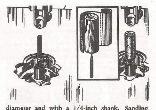
diameter and with a 1/4-inch shank. Sanding sleeves of various grits are available. Like filing, sanding must be done at low speeds to avoid glazing the abrasive.
| Width | * BOARD MEASURE | ||||||||||||||
|---|---|---|---|---|---|---|---|---|---|---|---|---|---|---|---|
|
in
Inches |
Length in Feet | ||||||||||||||
| 4 | 5 | 6 | 7 | 8 | 9 | 10 | 11 | 12 | 13 | 14 | 15 | 16 | 17 | 18 | |
| 2 | 0-8 | 0-10 | 1-0 | 1-2 | 1-4 | 1-6 | 1-8 | 1-10 | 2-0 | 2-2 | 2-4 | 2-6 | 2-8 | 2-10 | 3-0 |
| 3 | 1-0 | 1.3 | 1-6 | 1-9 | 2-0 | 2-3 | 2-6 | 2-9 | 3-0 | 3-3 | 3-6 | 3-9 | 4-0 | 4-3 | 4-6 |
| 4 | 1-4 | 1-8 | 2-0 | 2-4 | 2-8 | 3-0 | 3-4 | 3-8 | 4-0 | 4-4 | 4-8 | 5-0 | 5-4 | 5-8 | 6-0 |
| 5 | 1-8 | 2-1 | 2-6 | 2-11 | 3-4 | 3-9 | 4-2 | 4-7 | 5-0 | 5-5 | 5-10 | 6-3 | 6-8 | 7-1 | 7-6 |
| 6 | 2-0 | 2.6 | 3-0 | 3-6 | 4-0 | 4-6 | 5-0 | 5-6 | 6-0 | 6-6 | 7-0 | 7-6 | 8-0 | 8-6 | 9-0 |
| 7 | 2-4 | 2-11 | 3-6 | 4-1 | 4-8 | 5-3 | 5-10 | 6-5 | 7-0 | 7-7 | 8-2 | 8-9 | 9-4 | 9-11 | 10-6 |
| 8 | 2-8 | 3.4 | 4-0 | 4-8 | 5-4 | 6-0 | 6-8 | 7-4 | 8-0 | 8-8 | 9-4 | 10-0 | 10-8 | 11-4 | 12-0 |
| 9 | 3-0 | 3.9 | 4-6 | 5-3 | 6-0 | 6-9 | 7-6 | 8-3 | 9-0 | 9-9 | 10-6 | 11-3 | 12-0 | 12-9 | 13-6 |
| 10 | 3-4 | 4-2 | 5-0 | 5-10 | 6-8 | 7-6 | 8-4 | 9-2 | 10-0 | 10-10 | 11-8 | 12-6 | 13-4 | 14-2 | 15-0 |
| 11 | 3-8 | 4-7 | 5-6 | 6-5 | 7-4 | 8-3 | 9-2 | 10-1 | 11-0 | 11-11 | 12-10 | 13-9 | 14-8 | 15-7 | 16-6 |
| 12 | 4-0 | 5-0 | 6-0 | 7-0 | 8-0 | 9-0 | 10-0 | 11-0 | 12-0 | 13-0 | 14-0 | 15-0 | 16-0 | 17-0 | 18-0 |
| 13 | 4-4 | 5-5 | 6-6 | 7-7 | 8-8 | 9-9 | 10-10 | 11-11 | 13-0 | 14-1 | 15-2 | 16-3 | 17-4 | 18-5 | 19-6 |
| 14 | 4-8 | 5-10 | 7.0 | 8-2 | 9-4 | 10-6 | 11-8 | 12-10 | 14-0 | 15-2 | 16-4 | 17-6 | 18-8 | 19-10 | 21-0 |
| 15 | 5-0 | 6-3 | 7-6 | 8-9 | 10-0 | 11-3 | 12-6 | 13-9 | 15-0 | 16-3 | 17-6 | 18-9 | 20-0 | 21-3 | 22-6 |
| 16 | 5-4 | 6-8 | 8-0 | 9-4 | 10-8 | 12-0 | 13-4 | 14-8 | 16-0 | 17-4 | 18-8 | 20-0 | 21-4 | 22-8 | 24-0 |
| 17 | 5-8 | 7-1 | 8-6 | 9-11 | 11-4 | 12-9 | 14-2 | 15-7 | 17-0 | 18-5 | 19-10 | 21-3 | 22-8 | 24-1 | 25-6 |
| 18 | 6-0 | 7.6 | 9-0 | 10-6 | 12-0 | 13-6 | 15-0 | 16-6 | 18-0 | 19-6 | 21-0 | 22-6 | 24-0 | 25-6 | 27-0 |
tables
*The price of a board is computed on the basis of the number of board feet contained in the board. One board foot is equivalent to the amount of stock contained in a piece of board one foot long, one foot wide, and one inch thick. (For purposes of board feet computation, stock which is less than one inch thick is generally considered to be one inch stock.) To determine the number of board feet in a board by use of the above table proceed as follows. Find the vertical column which corresponds to the length of the board (in feet). Then run down this column to the figure which is horizontally opposite the proper width in inches indicated in the side heading. This figure will be the number of board feet in the particular board. If the board is greater than one inch, multiply the figure indicated in the table by the actual thickness dimension of the board.
For a board which is eight feet long, eight inches wide, the one inch thick, it will be found that the table indicates a figure "5-4". (The second digit, "4" indicates the fractional portion, in twelfths, of a board foot — 4/12 foot.) Thus, the board feet contained in the board is 5-4/12 feet or 5-1/3 feet. If the board were two inches thick, then it would be necessary to multiply 5-4 by 2. The total board feet then would be 10-8 or 10-2/3 feet.
- 32-

Power Tool Handbooks
ears'
give you complete, up-to-the-minute instructions for set-up, adjustments and proper handling of each tool — including hundreds of standard operations, short-cuts and special operations. All fully illustrated and described. Ask for these handbooks:
The Circular Saw
- The Drill Press
- The Wood Lathe
- The Jig Saw and Band Saw
- The Jointer. Shaper and Thickness Planer
- How to Sharpen
Power Tools - How to Use Them
AVAILABLE AT ALL SEARS RETAIL AND MAIL ORDER STORES


 Loading...