

Sears | Craftsman 9-2916 Craftsman Jointer, Shaper, & Bench Sander Operation Guide Instruction Guides

DECIMAL EQUIVALENTS
| 1 | the second se | ||
|---|---|---|---|
| 1/64 = .015625 | 1/4 = .250 | 1/2 = .500 | 3/4 = .750 |
| 1/32 = .03125 | 17/64 = .265625 | 33/64 = .515625 | 49/64 = .765625 |
| 3/64 = .046875 | 97/32 = .28125 | 17/32 = .53125 | 25/32 = .78125 |
| 19/64 = .296875 | 35/64 = .546875 | 51/64 = .796875 | |
| 1/16 = 0625 | |||
| 5/64 - 078125 | 5/16 = .3125 | 9/16 = .5626 | 13/16 = .8125 |
| 3/32 - 09375 | 21/64 = .328125 | 37/64 = .578125 | 53/64 = .828125 |
| 7/64 - 100275 | 11/32 = .34375 | 19/32 = .59375 | 27/32 = .84375 |
| 1/04109315 | 23/64 = .359375 | 39/64 = .609375 | 55/64 = .859375 |
| 1/9 - 125 | · | ||
| 1/6125 | 3/8 = .375 | 5/8 = .625 | 7/8 = .875 |
| 9/64 = .140625 | 25/64 = .390625 | 41/64 = .640625 | 57/64 = .890625 |
| 5/32 = .15625 | 13/32 = .40625 | 21/32 = .65625 | 29/32 = .90625 |
| 11/64 = .171875 | 27/64 = .421875 | 43/64 = .671875 | 59/64 = .921875 |
| 3/16 - 1875 | 7/16 - 4275 | 11/16 - 6976 | 15 (10 0075 |
| 12/64 - 202105 | 1/10 = .4375 | 11/16 = .08/5 | 15/16 = .9375 |
| 13/04 = .203125 | 29/64 = .453125 | 45/64 = .703125 | 61/64 = .953125 |
| 7/32 = .21875 | 15/32 = .46875 | 23/32 = .71875 | 31/32 = .96875 |
| 15/64 = .234375 | 31/64 = .484375 | 47/64 = .734374 | 63/64 = .984375 |
| Width | * BOARD MEASURE | ||||||||||||||
|---|---|---|---|---|---|---|---|---|---|---|---|---|---|---|---|
|
in
Inches |
Length in Feet | ||||||||||||||
| 4 | 5 | 6 | 7 | 8 | 9 | 10 | 11 | 12 | 13 | 14 | 15 | 16 | 17 | 18 | |
| 2 | 0-8 | 0-10 | 1-0 | 1-2 | 1-4 | 1-6 | 1-8 | 1-10 | 2-0 | 2-2 | 2.4 | 2-6 | 2-8 | 2.10 | 3-0 |
| 3 | 1-0 | 1.3 | 1-6 | 1.9 | 2-0 | 2-3 | 2-6 | 2.9 | 3-0 | 3-3 | 3.6 | 3-9 | 4-0 | 4-3 | 4-6 |
| 4 | 1-4 | 1-8 | 2-0 | 2-4 | 2-8 | 3-0 | 3-4 | 3-8 | 4-0 | 4-4 | 4-8 | 5-0 | 5.4 | 5-8 | 6-0 |
| 5 | 1-8 | 2-1 | 2-6 | 2-11 | 3-4 | 3-9 | 4-2 | 4.7 | 5-0 | 5-5 | 5-10 | 6-3 | 6-8 | 7-1 | 7-6 |
| . 5 | 2-0 | 2.6 | 3-0 | 3-6 | 4-0 | 4-6 | 5-0 | 5-6 | 6-0 | 6-6 | 7.0 | 7-6 | 8-0 | 8-6 | 9-0 |
| 7 | 2-4 | 2-11 | 3-6 | 4-1 | 4-8 | 5-3 | 5-10 | 6-5 | 7-0 | 7-7 | 8-2 | 8-9 | 9.4 | 9-11 | 10-6 |
| 8 | 2-8 | 3-4 | 4-0 | 4-8 | 5-4 | 6-0 | 6-8 | 7-4 | 8-0 | 8-8 | 9-4 | 10-0 | 10-8 | 11-4 | 12-0 |
| 9 | 3-0 | 3.9 | 4-6 | 5-3 | 6-0 | 6.9 | 7-6 | 8-3 | 9-0 | 9.9 | 10-6 | 11-3 | 12.0 | 12.9 | 13-6 |
| 10 | 3-4 | 4-2 | 5-0 | 5-10 | 6-8 | 7-6 | 8-4 | 9-2 | 10-0 | 10-10 | 11-8 | 12-6 | 13.4 | 14-2 | 15-0 |
| 11 | 3-8 | 4-7 | 5-6 | 6-5 | 7.4 | 8-3 | 9-2 | 10-1 | 11-0 | 11-11 | 12-10 | 13-9 | 14-8 | 15-7 | 16-6 |
| 12 | 4-0 | 5.0 | 6-0 | 7-0 | 8-0 | 9-0 | 10-0 | 11-0 | 12-0 | 13-0 | 14-0 | 15-0 | 16-0 | 17-0 | 18-0 |
| 13 | 4-4 | 5-5 | 6-6 | 7.7 | 8-8 | 9.9 | 10-10 | 11-11 | 13-0 | 14-1 | 15-2 | 16-3 | 17-4 | 18-5 | 19-6 |
| 14 | 4-8 | 5-10 | 7-0 | 8-2 | 9-4 | 10-6 | 11-8 | 12-10 | 14-0 | 15-2 | 16-4 | 17-6 | 18-8 | 19-10 | 21-0 |
| 15 | 5-0 | 6-3 | 7-6 | 8-9 | 10-0 | 11-3 | 12-6 | 13-9 | 15-0 | 16-3 | 17-6 | 18-9 | 20-0 | 21-3 | 22-6 |
| 16 | 5-4 | 6-8 | 8-0 | 9-4 | 10-8 | 12-0 | 13-4 | 14.8 | 16-0 | 17 4 | 18-8 | 20-0 | 21-4 | 22-8 | 24-0 |
| 17 | 5-8 | 7-1 | 8-6 | 9-11 | 11-4 | 12-9 | 14-2 | 15-7 | 17-0 | 18-5 | 19.10 | 21-3 | 22-8 | 24-1 | 25-6 |
| 18 | 6-0 | 7.6 | 9-0 | 10-6 | 12-0 | 13-6 | 15-0 | 16-6 | 18-0 | 19.6 | 21.0 | 22.6 | 24-0 | 25-6 | 27.0 |
*The price of a board is computed on the basis of the number of board feet contained in the board. One board foot is equivalent to the amount of stock contained in a piece of board one foot long, one foot wide, and one inch thick. (For purposes of board feet computation, stock which is less than one inch thick is generally considered to be one inch stock.) To jetermine the number of board feet in a board by use of the above table proceed as follows. Find the vertical column which corresponds to the length of the board (in feet). Then run down this jeturn to the figure which is horizontally opposite the proper width in inches indicated in the side heading. This figure will be the number of board feet in the particular board. If the board is geater than one inch, multiply the figure indicated in the table by the actual thickness dimension of the board.
For a board which is eight feet long, eight inches wide, and one inch thick, it will be found that the table indicates a figure "5-4". (The second digit, "4" indicates the fractional portion, in twelfths, of a board foot — 4/12 foot.) Thus, the board feet contained in the board is 5-4/12 feet or 5-1/3 feet. If the board were two inches thick, then it would be necessary to multiply 5-4 by 2. The total board feet then would be 10-8 or 10-2/3 feet.
INDEX
THE IOINTER
GENERAL INFORMATION ..... 2-3 Selection - Controls - Accessories
SET-UP AND ADJUSTMENTS . 4-5 Mounting and Adjustments
STD. JOINTER OPERATIONS....6-10 Hand Positions — Test Cuts — Surfacing — Edge and End Jointing — Squaring — Tapering
MISC. JOINTER OPERATIONS .... 11
THE SHAPER
SET-UP AND ADJUSTMENT ... 12-13 Selection - Controls - Adjustments
SHAPER OPERATIONS . . 14-18 Set-Up - Operating Techniques -Uses of Guides and Collars
SHAPING WITH PATTERNS AND FORMS ....................................
MISC. SHAPER OPERATIONS . . 24-25 Jointing - Taper Jointing - Panel Raising - Dowels - Designs
THE MOLDING HEAD ....................................
THE BENCH SANDER
GENERAL INFORMATION ..... 27 Usage – Selection – Mounting
SANDER ADJUSTMENTS ..... 28
BELT SANDING OPERATIONS . . 29-30 Belts – Surfacing – Edge and End Sanding – Beveling – Drum Sanding – Slack-Belt Sanding – Use of Forms
DISC SANDING AND JIGS ....................................
TABLES ....................................
Jounter, Shaper ANI Rench
An Illustrated Manual of Operation for the .
HOME CRAFTSMAN SHOP OWNER
SELECTING YOUR POWER TOOL PROPER SET-UPS – ALL NECESSARY ADJUSTMENTS – USE OF CONTROLS PLANNING YOUR WORK STANDARD OPERATIONS SPECIAL OPERATIONS
OVER 200 ILLUSTRATIONS
A CRAFTSMAN POWER TOOL HANDBOOK
Catalog No. 9-2916 A MIDWEST TECHNICAL PUBLICATION
Copyright 1965 SEARS, ROEBUCK and CO. REVISED 1965
rinted in U.S.A
REAR TABLE CUTTER GUARD FENCE FRONT TABLE HANDWHEEL CUTTER GUARD PROTRACTOR SCALE PROTRACTOR SC
4-1/8 IN. JOINTER
SEARS MODERN JOINTERS
WHY A JOINTER IS NEEDED IN THE WORKSHOP
The jointer is a power tool designed especially to do the work formerly done with a hand plane. Not only will the jointer do the work much faster — it will also do it much better, if kept in proper operating condition. We would like to show you how you can produce the quality of work, with your jointer, necessary for craftsman-like cabinet making. Straight and true joints, that will fit together with hardly a visible space between, can easily be produced, even by inexperienced workers . if proper care is taken to make the set-ups and perform each operation correctly.
SELECTING A JOINTER AND MOTOR
Jointers are made in a variety of sizes for light, heavy, and special duty work. Well constructed machines are equipped with ball or roller bearings which are enclosed in dust-proof housings — and have tilting fences so that bevel jointing can be accomplished easily. The knives (or cutters) are fitted into a cylindrical head which revolves at a very high speed — generally between 3600 to 4500 rpm. There may be two, three or four knives in the head. These
jointers also can be used for planing operations as well as for jointing. The practical maximum width board which can be planed on a jointer is just under twice the width of the jointer table (i.e. - the rated size).
When selecting a motor, be careful not to underpower your jointer. Satisfactory work cannot be done at slower than the recommended spindle speeds. In general, a 1/3 or 1/2 h.p. motor should be used for a 4-inch jointer; a 1/2 or 3/4 h.p. motor for a 6-inch jointer; and a 3/4 or 1 h.p. motor for an 8-inch jointer. Manufacturers always specify proper motor capacity and pulley diameters.
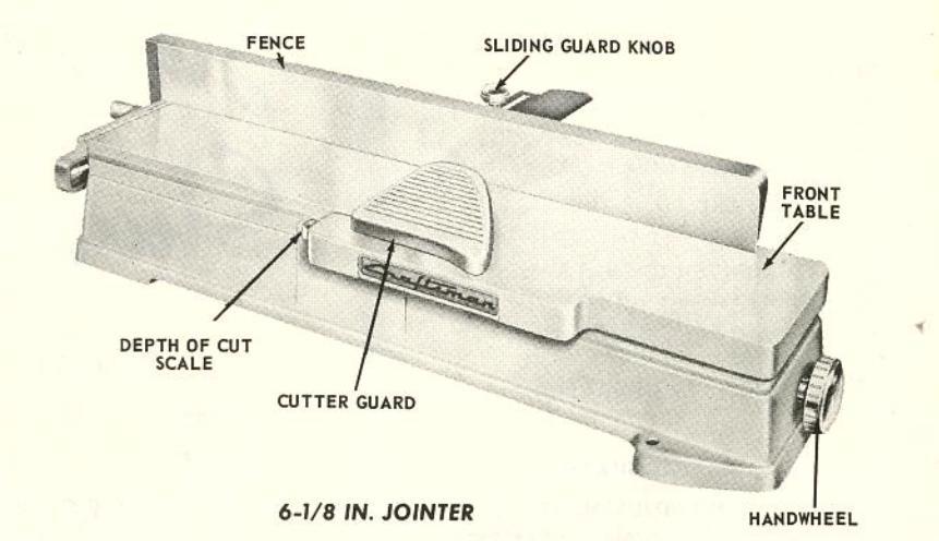
OPERATING CONTROLS
Typical controls are shown in the illustrations on page 2. Instructions packaged with each jointer explain their uses. In general, the Rear Table is stationery at a height, with relation to the cutter head, to receive the finished work . while the Front Table (on which the work is started) is adjustable up or down to vary the depth of cut. Better tools also have an adjustable Fence . which can be positioned on the table, and can be tilted to guide a bevel cut.

SET-UP AND ADJUSTMENTS

SETTING UP YOUR JOINTER
Mount your Jointer on a solid pedestal, bench or workbench so that the surface of the table top is approximately 32 inches above the floor. It should be as nearly level as possible. Install the motor below the cutter-head pulley, either on a motor rail or on a wooden shelf which is adjustable to provide proper belt tension. The motor must drive the cutter head clockwise, when the front table is at your right.
GENERAL INFORMATION
Exact adjustments are absolutely necessary if your Jointer is to accomplish the accurate work for which it has been designed. Proper instructions are packaged with each tool . read them carefully, and recheck the adjustments often to be certain tool is operating properly.
In general, the important adjustments for good work are as follows:
1) Depth of Cut. This is indicated by a scale and pointer, which moves as the front
table is raised or lowered. The pointer may become out-of-adjustment . or the front table may become tilted with respect to the stationary rear table and cutter head . or the cutter head (if it is an adjustable type) may become tilted with respect to the two tables. Some tools have leveling jacks to level the front table with respect to the rear table; some have jacks for leveling the rear table; and some have adjustable cutter-head arbor brackets for leveling the cutter head.
2) Fence Tilt. Models having a tilting fence are provided with a scale and pointer to indicate degrees of fence tilt (for bevel operations). Usually, the pointer (or scale) can be loosened for readjustment if needed.
3) Fence Stops. Some models have 45° and 90° (tilt) stops . for quick setting of fence tilt at these positions. Such stops are adjustable.
LEVELING THE TABLES

Whatever provisions your Jointer has, level the two tables, with respect to each other. when the Depth-of-Cut Pointer is exactly at zero. First, bring the Front Table surface into flush alignment – as nearly as possible – with Rear Table surface. You can check this by holding a straightedge across the two tables. Adjust the Depthof-Cut Pointer to read zero on its scale. Check the flushness of the two tables endto-end and crosswise by moving the straightedge over their surfaces. If straightedge lies flat on Rear Table and adjoining edge of Front Table, but shows a gap at far edge of Front Table, then far (outer) end of Front Table is too low ... and vice-versa. Also, if straightedge lies flat across full length of both Rear and Front Table at the front, but shows a gap when moved back (toward fence), then
Front Table is tilted and back side needs raising . . or vice-versa. Slide the straightedge all over the surface and check for gaps or high spots anywhere . . and adjust Front Table until a perfect, allover level is achieved.
CUTTER-HEAD ALIGNMENT
If your tool has such an adjustment, set the Depth-of-Cut at zero. Place a straightedge across the tables at the front. It should just touch . but not be cut by . the knives when cutter head is rotated. Move it to rear position . and, again, it should just touch the rotating knives. Adjust cutter head and or tables so that this is so.
SETTING FENCE ANGLE POINTER AND STOPS

Protractor Scale with a Pointer. Either the scale or the pointer . or both . can be loosened for repositioning. Use an accurate square and manually set the fence exactly at 90° to the tables. Now adjust the scale or pointer so that the reading will be 90°. By same method, recheck and adjust the 45° setting . and adjust stops (if these are provided) at the 90° and 45° positions.
RE-SETTING CUTTER KNIVES
After re-sharpening the cutter-head knives it is necessary to re-set them in the cutter head. This is a very important operation, and must be carefully done. Two of the best methods for re-setting the knives are described below.

In method No. 1 the front table is fully elevated so that a straightedge will touch both tables at all points. Install the knives in the


cutter head with each knife projecting slightly above the tops of the tables, and with the outer end of the knife projecting exactly 1/16 inch outward from the cutter head. Clamp each knife lightly into position with the set screws and wedge provided. Be sure to engage the points in the set screws in the slots of the wedge.
Now rotate the cutter head by hand to position one knife at its highest point — then tap the knife down with a wooden block until the top edge of the knife is exactly level with the surfaces of the two tables from end to end. Check this with the straightedge — then tighten the set screw securely. Adjust the other two knives in the same manner.

The second method makes use of a magnet. Clamp a block of wood across the front table to act as a stop for the magnet. The edge of this block must be exactly parallel with the slots in the cutter head. Place the magnet on the rear table with the two ends butting against this stop block. Insert one knife into the cutter head, and rotate the head to place this knife at its highest position. The magnet will now draw the knife up out of the cutter head, so that the top edge of the knife is exactly level with the surfaces of the two tables. Tighten the set screws which hold this knife; then proceed to set the other knives in like manner.
OPERATING INSTRUCTIONS
CORRECT HAND POSITIONS
In determining hand positions, two things must be kept in mind: 1) The fingers must not be allowed to pass dangerously close to the revolving blades; 2) The work must be kept in solid contact with the table tops, if a straight true cut is to be made. In general there are two methods of accomplishing this.

First, and quickest, is the "follow through method. The hands are placed on top of the work so that the left hand will be above the front edge of the rear table just as soon as enough of the work has passed over the work firmly down on the rear table to obtain a true cut. As the work progresses. work so that it will remain approximately above the front edge of the rear table. The the work where it can be used to simultaneously hold the work down on the front table and to push the work forward across the knives. It remains in this position on the work until the cut is completed - and therefore passes directly over the knives as the back end of the work is finished. When using the hands thusly, care must be taken to pull the thumb upward to a safe height above the knives as the right hand
The second method is best when surfacing boards, especially thin boards — and does not require either hand to pass over the knives. At the start, both hands are kept on top of that part of the work which rests on the front table. When enough of the work has passed onto the rear table, the left hand is lifted up and moved through the air to rest on top of the portion of the work now on the rear table. Similiarly, as the front edge of the work approaches the cutter head, the right hand is also lifted and moved to the rear table. As in the case of the first method, the left hand is used entirely to

hold the work firmly down while the right hand is used both for holding the work down and for propelling it over the knives.
Special hand holds are required when jointing the edge of a very wide board, or when jointing the end of a board which will project twelve or more inches upward from the table. Obviously, support must be given to the board to keep it from rocking to the right or left — and the left hand is therefore used principally to push the board over against the fence to keep it squarely upright. If the board extends high enough above the table, the weight of the board will hold it down, and the right hand can be used to propel it over the knives; otherwise, the right hand should be on top of the board to both hold it down and propel it.
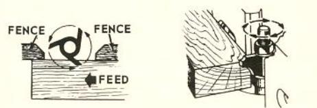
MAKING AND TESTING A CUT
Unless a special operation requires otherwise, always cut with the grain of the wood — as illustrated. If necessary to cut against the grain, move the workpiece at about one-half normal speed across the cutter head, and slow down even more when approaching the end of the workpiece. This will prevent the knives from splitting the end of the workpiece.
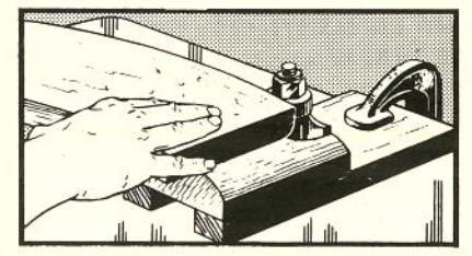
Edge or rabbet cuts up to 1/2-inch depth can be made on a 4-inch jointer — but best results are obtained with maximum cuts of 1/8 to 3/16-inch deep, and by making successive cuts to obtain greater depths. The depth of a cut that is made can be accurately measured, prior to completion of the cut, as illustrated. When it is necessary to make a single deep cut, feed the work at a slower rate than normal to keep from slowing down the cutter head. If the cutter head slows down too much, the cut will be very rough.

JOINTER OPERATIONS
SURFACING
General Set-Up
Adjust the front table so that about a 1/32inch cut will be made. The depth of cut can be estimated by sighting the difference between the levels of the two tables.
Set the fence at a right angle to the surfaces of the two tables. Generally speaking, the procedure now involves nothing more than pushing the work across the cutter head, using the hands as already explained on page 6. Before doing this, however, survey the work carefully to note whether it has either warp and/or wind. If it has, proceed as follows:
Boards With Warp and/or Wind


Warped lumber is dished from side to side across the board. Such workpieces are preferably surfaced on the dished or concave side, as the two edges of the board will rest on the table top to keep the board from rocking. Whenever it is necessary to surface the convex side of such a workpiece, always hold the work firmly to prevent its rocking while passing over the cutter head. In either case, make a sufficient number of passes over the cutter head to reduce the work to a flat surface.

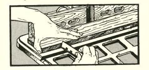
Wind is a twisting of the workpiece from end to end. Testing for wind can be done by sighting — or by rocking the board on a flat surface, as illustrated above. When a workpiece is to be surfaced out of wind it is advisable to mark the work carefully to permit surfacing with the least number of cuts. This will avoid loss of workpiece thickness. After marking, support the workpiece so as to first remove material only
at the part where the most material must be removed — and in successive passes enlarge the area of cut until it finally takes in the entire underside of the workpiece.
When it is necessary to hold one edge or one corner of the workpiece up off the table top in order to remove wood from a low corner or edge to correct wind, good use can be made of small blocks of wood nailed or clamped to workpiece edges. These blocks should be positioned so that they will ride on top of the tables and guide the workpiece over the cutter head on a level plane.
Thin Boards
A pusher shoe which will help you to both propel the work across the cutter and to hold the work down, at the same time, is very handy for surfacing operations. Such a shoe is particularly desirable when surfacing very thin boards, as it keeps the hands a safe distance away from the cutter knives. A design for a simple homemade pusher; shoe is illustrated. The small block projects down below the bottom surface of the larger block just enough so that it can be hooked behind the end of the workpiece to push it forward. It should not project down far enough to contact the cutter knives when the shoe is pushing the end of the work over the cutter head.

An even simpler pusher shoe can be constructed by fastening narrow blocks of wood to the top of the large block, in place of the handle and knob. It is only necessary that some means be provided for holding the top of the shoe securely with both hands. The shoe should be long enough to firmly press the work down on the tables, from end to end.


1
STANDARD OPERATIONS

PENCE
The tops of very thin boards will be lower than the bottom edge of the fence adjacent to the rear table, so that the fence will not serve as a proper guide. This makes it necessary to use an auxiliary fence when surfacing such thin boards — as illustrated.
Wide Boards
Boards up to twice the width of the cutter head, less approximately 1/4-inch allowance for over-lap, can be surfaced on your machine. Simply make two passes of the board over the cutter head, without changing the height of the front table. The first cut will surface one-half of the board; turn the board completely around to surface the other half. One or the other of the two cuts must necessarily be made against the grain of the wood. Do the first cut in this manner, leaving the "with the grain" cut for the last. When making the "against the grain" cut, feed the workpiece at approximately one-half the normal speed, and feed extremely slowly at the very end of the cut.
Long Boards
Very long boards create a problem because it is difficult to simultaneously handle the unwieldy board, and to press it down properly against the table tops. A hold-down fastened to the fence above the rear table is a great help. Either a wood or metalleaf spring will serve this purpose. It should be clamped to the fence so that the edge of the board can pass between the spring and the top of the rear table — and so that the spring will hold the board firmly down onto the rear table.
Very Short Boards
Generally speaking, it is not practical to surface boards under 12 inches in length, because shorter boards do not provide sufficient hand hold leverage to offset the kickback of the cutter head. A longer board
can be placed on top of a short workpiece to propel it over the cutter head. The longer board can either be nailed to the workpiece - or, as illustrated, can be recessed on the under side to "grip" the workpiece.
EDGE JOINTING
This is the simplest and most common operation which can be done on the jointer. In general, approximately 1/8 inch of material should be the maximum removed in any one pass of the workpiece over the cutter head. Set the fence very carefully at a right angle to the table top. The workpiece is held and fed across the cutter head as already explained.
Fairly rough edges can be successfully jointed — but it is usually quicker and easier to cut off extremely rough edges on a band or bench saw, prior to jointing.
Dished and Bowed Edges
Dished (concave) edges present no great difficulty, if the whole length of the board table; however, an auxiliary support must be provided to hold this end up at exactly the same level with the end on the table. Jointing the bowed (convex) edge of a board is difficult because there is a tendency for the board to rock end-to-end. This is difficult to overcome without the aid of some type of support. The best practice is to clamp two short pieces of scrap stock to the board, one at each end so that the board will pass over the cutter head on a level plane. If the board is too long for the front block to rest on the table top at the start of the cut, use an auxiliary table.
Wide Boards
The low fence provided with most jointers is not high enough to properly support very wide boards, when edge jointing — and there is a tendency for the board to wobble from side to side during the operation. For this reason, it is advisable to attach an auxiliary fence to the regular fence — and to have this auxiliary fence high enough so that the workpiece can be pressed firmly against it to prevent wobble.

Very Rough Edges
A very rough edge can be successfully jointed if you remember to put all of the "down pressure" on that portion of the workpiece which is above the rear table. Do not put any "down pressure" on the end of the work which is on the front table, and which still has an uneven bottom edge.
End Jointing
End jointing is much the same as edge jointing; except that there is a tendency for the wood to split at the back end as this end is passed over the cutter head. For this reason, two cuts — one from each edge of the board — are generally better than one straight cut. Make the first cut long enough to carry past the second or third grain of the wood at one edge. Turn the board around and make the second cut to overlap the first and give a straight edge. Do not make the first cut too long. A long enough edge must be left to keep the board steady on the top of rear table while finishing the second cut.
Dished and bowed ends are handled in the same manner as dished and bowed edges. When the board is very long (therefore standing high in the air above the table) it is advisable to provide some means of supporting it without its wobbling. Support can sometimes be provided by a horizontal board clamped to the workpiece and arranged to ride along an auxiliary support placed at the right side of the jointer.
SQUARING A BOARD
The first step in squaring all six sides of a board is to surface one side (preferably the side which is easiest to surface) in order to obtain a "working face." The two ends are then jointed; and afterwards the two edges are jointed. End and edge jointing are done with the working face pressed against the fence so that these joints will be square with the working face. The sequence of end and edge jointing steps is shown in the accompanying illustration.
After jointing the ends and edges, proceed to surface the remaining face as follows: Cut four small wood blocks of equal length, and glue these to the edges of the board near the four corners in such manner that they will support the board with the working
face on top and parallel with the front table of the jointer. These blocks should be just long enough to accomplish this purpose, and should not extend downward below the level of the lowest point on the unsurfaced side of the board. Now surface the underside of the board, making as many cuts as necessary to reduce it to an absolutely smooth surface.
To test a board or boards for squareness, use a good square, as illustrated. The square should contact the faces of the board or boards at all points, so that no light can shine through.
TAPER JOINTING
Taper jointing is very useful in making table legs like those illustrated, and for numerous other cabinet making operations.
Straight Tapers
The simplest tapering operation is done with workpieces shorter in length than the front table. Set-up as follows: Lower the front table to make approximately a 1/8 inch cut. Place the workpiece on top of the front table and against the fence — with the back edge barely resting on the edge of the rear table adjacent to the cutter head. With the workpiece in this position, clamp a piece of scrap wood to the front table so that it will butt up against the end of the workpiece.
After the set-up is made, remove the workpiece and start the jointer. Now place the end of the workpiece against the block clamped to the front table (as it was during the set-up), and lower the other end onto the cutter head until portion just behind the cutter head (which will be uncut) rests on the rear table (as in the set-up). Starting thus, advance the work across the cutter head. The uncut portion which was resting on the rear table at the start will hold this end high, so that the resulting cut will be tapered toward the other end of the work-

piece. Continue lowering the front table approximately 1/8 inch at a time and make additional cuts in this same manner until the narrow end of the taper is as deep into the workpiece as desired.
If the workpiece is longer than the length of the front table, exactly the same procedure can be used — but an auxiliary extension must be fastened to the front table so that the entire workpiece will have a level surface to rest upon. If the front table is to be lowered for additional cuts, this extension must be lowered also.
A TWO-SECTION TAPER Begin 2nd. taper Begin 1st. taper REAR REAR TABLE Begin 1st. cut Begin 1st. cut
A long taper can be cut without an extension. Lay out the taper and divide the area to be tapered into sections, each section several inches shorter than the length of the front table. A first cut will start at the section line nearest the tapered end of the workpiece. This first cut must remove either 1/2, 1/3, etc. of the total amount of stock to be removed from the workpiece end. Each successive cut will remove a like amount of the remainder — and these successive cuts will start at the second, third, etc. section lines and run out to the workpiece end.
Compound Tapering
A compound taper is made when a second taper, at a greater angle than the original taper, is cut at one end of a tapered workpiece. Compound tapers can include two, three or more tapers — each at a greater angle than the adjoining taper.
To cut a compound taper, cut the first taper as already explained — then make a new set-up with the stop block arranged so that the workpiece will drop down onto the cutter edge at the point selected for starting the second taper. The second taper can then be cut in exactly the same manner in which the original taper was cut.


Stopped Tapers
A stopped taper is one which does not run all the way to the end of the workpiece. This type of cut is widely used in making table legs — a good example of this is illustrated above.
A stopped taper can be freehand cut by using the same procedure given above for cutting straight tapers. It is only necessary to start and stop the cut at the proper places. For this reason, the best practice is to lay out your plan for the taper on the workpiece, as illustrated above. The starting line (A) should be directly above the highest point of the cutter head (approximately one inch to the front of the rear table front edge) at the start. The stopping line (B) should be approximately above the back edge of the front table at the end of the cut — and the workpiece should be lifted straight up off the cutter head when this point is reached.
It will be easier to handle the workpiece if the fence is moved as close to the left edge of the machine as the width of the workpiece will permit. If it is necessary to watch the guide lines, the cutter guard must either be removed — or must be tied back out of the way. Stop blocks, clamped to the front and rear tables as illustrated, will make it easy to cut uniform stopped tapers on all four sides of one or more workpieces. A set-up must be made before starting the machine and the blocks should be arranged so that the workpiece will butt against the one on the front table when the starting line (A) is correctly positioned for the start of the cut — and so that the stop block on the rear table will be bumped by the workpiece, when the finish line (B) is correctly positioned for the end of the cut.

MISC. JOINTER OPERATIONS
BEVEL JOINTING
Bevel jointing is done by tilting the fence to the desired angle, as indicated by the fence angle pointer and protractor scale. The fence can be tilted either in or out; but the latter is easier.
Once the fence has been set to the desired angle, the operation is like edge jointing. Chamfering is done in the same manner; but only a small portion of the edge is removed. Taper cutting also can be done with the fence tilted, to produce a beveled taper.
RABBETING
Rabbets — or edge grooves — are easily cut on your jointer. Move the fence over to the outer edge of the jointer so that you will obtain the desired width of cut when the workpiece is pressed against the fence. Now make the cut in the same manner used for surfacing. As many cuts as necessary to obtain the desired depth of cut can be made. Also, successive cuts can be made with different fence settings to obtain stepped rabbets like those illustrated above.
Beveled rabbets and tapered rabbets can also be easily cut by combining the technique for rabbeting with the set-ups used for bevel and or taper cutting. When cutting rabbets in very thin stock, be sure to use a pusher shoe as explained in "Surfacing."
HANDLING SMALL STOCK
When jointer operations on very small stock are being done, it is advisable to move the fence outward as near to the edge of your machine as the size of the stock will permit — so that you can work from the side of the machine without having to put your hands over the cutter head. Guide blocks both to hold the work against the fence and to hold the work down against the cutter head — should be used as illustrated below. When doing this type of work, it is necessary to remove the guard — and every precaution should be taken to keep the hands away from the cutter head.
CUTTING ROUND TENONS
A round tenon at the end of a round workpiece can be cut in much the same manner as a rabbet. If the fence is set all the way over to the edge of the jointer, the workpiece can be pressed directly against the fence — but it is often easier to use a stop block (as illustrated) to set the depth of cut. In either case, a block of wood should be clamped to the front table to hold the workpiece over against the cutter head — and this set-up must be made before starting. Afterwards, start the jointer and lower the workpiece onto the cutter head, pressing it down flat on the table. Slowly revolve the workpiece — pressing it against the stop block — and turing it in the same direction in which the cutter head is rotating.
The same technique can be used to cut a round tenon at the end of a square workpiece, if a round ring of metal or wood is placed around it to provide a surface on which the workpiece can be revolved.
TAPERING IN-THE-ROUND
Round tapers — also widely used in furniture legs — can be made by making a series of straight tapers to reduce the workpiece to an octagon shape. The octagon workpiece is then mounted in a fixture to be simultaneously tapered and reduced to a nearly round shape. It is finished by sanding.
A homemade guide to aid in obtaining cuts of equal depth around the workpiece is illustrated. The workpiece is first laid out as for all taper operations — and is then mounted in the guide, the pin at the left being set up from the bottom of the guide a distance equal to one-half the diameter of the finished workpiece at the end. The other pin is set up a distance equal to onehalf the finished diameter at the small end of the taper. In use, the guide block is pressed against the fence — and successive cuts are made, turning the workpiece approximately 10° to 15° for each new cut.
Two types of legs — one a perfect round taper, the other a quarter-round taper with flat tapered sides are the most common. These and many other shapes are easily made by combining tapering-in-the-round with straight and bevel tapering operations.

11
THE SHAPER
HOLD-DOWN FINGER -HOLD-IN FINGER CONTROL LEVER

SHAPER COLLARS

FINISHING WORK REQUIRES A SHAPER
A shaper has a vertical spindle designed to hold various types of cutters. The different shapes of cutters (illustrated below) are quickly fitted onto the spindle, so that a variety of work can be accomplished. An adjustment is provided so that the spindle can be raised or lowered to accomodate cuts of different thicknesses — and a second adjustment locks the spindle in position.
SELECTING YOUR SHAPER AND MOTOR
The illustrated shaper with 1/2-inch spindle is the most practical for the average workshop. This well designed shaper has lifetime lubricated spindle bearings, an adjustable type spindle, a fence having both faces - instead of just one - readily adjustable forward and backward: and a spindle which
With a medium sized shaper, a 1/2 h.p. motor should be used, and the motor should have a speed of 3450 rpm. If the shaper is adapted to cutters having bores of 3/4 3/4 to 1 h.p. should be used. Whatever type of motor is selected, actual spindle speed should be approximately 9000 rpm. A reversing switch or reversible type motor is preferable as it is often desirable to operate the spindle counterclockwise (normal rotation is in a clockwise direction).
High-speed cutters available for your shaper are illustrated. By combining these various cutters, you can make hundreds of additional shaper cuts. Shaper collars greatly increase range of work by providing ready means to control the denth of cut Two sets give all desired variations and combinations of set-ups.
OPERATIONS & ADJUSTMENTS

OPERATING CONTROLS
The control lever is used to raise or lower the spindle when the guill lock handle is loosened (turned counterclockwise). Rotating the lever clockwise lowers the spindle and vice-versa. Always tighten the quil lock handle after setting spindle at desired height. In general, the lever will raise or lower the spindle approximately 7/8 inch to accomodate various size cutters.
Either fence face is moved forward or backward by the micrometer-type knurled adjusting collar, when the lock knob is loosened (turned counterclockwise). Always the fence faces.
FENCE FACES
The opening between the two faces of the fence should never be larger than is required to clear the cutter. Each face will slide 1 inch - so that the opening can be varied from 1 to 3 inches. To adjust opening, loosen the two screws which hold each fence face to the fence frame, slide the faces into the desired position - then securely re-tighten the screws.
AD IUSTING THE HOLD-DOWN AND HOLD-IN FINGERS
Each hold-down and hold-in finger is adjustable upon the holding arm which supports them. Loosen finger by loosening the sockethead set screw in the holding bracket in
which the finger is mounted. The finger now can be pulled through the bracket to any desired position and tipped to any desired angle on the holding arm. The entire arm can be moved in or out of the bar which supports it, and can be rotated on the bar, by means of a third socket-head set screw at the top of the bar.
Always adjust the hold-down and hold-in the fence and down on the table, as it is being fed into the cutter. In case reverse cutter rotation is being used, the entire finger assembly can be moved to the opposite (right hand) side of the fence by loosening the set screw of the holding bar and the right half of the fence.
ADJUSTING FENCE PARALLEL TO MITER GAGE GROOVE
Whenever the miter gage is to be used, it is necessary that the fence be exactly parallel to the groove. To accomplish this, first adjust the two fence faces so that both are either all the way back, or all the way forward. Place a straightedge against the two fence faces and check their alignment. If they are not in perfect alignment, adjust as required to make the alignment perfect. then tighten both adjustments. Now loosen the two holts which secure the fence frame to the table top, and measure the distance between each end of the straightedge (still pressed against fence faces) and the miter gage groove. Shift the fence as necessary to equalize the two measurements. When the measurements are equal, retighten the bolts that secure fence frame to the table.


GENERAL SHAPER OPERATIONS
MAKING THE SET-UP
Cardboard cutouts, each trimmed at one edge to the pattern produced by one of your cutters, will make it easy to plan compound patterns for moulded edges. Match the cutouts together, as illustrated, to produce any desired moulded edge — and to plan the necessary cuts.
When you have selected a pattern for the moulded edge, trace the pattern on the end of the workpiece. If work is round, trace pattern on the end of a scrap board of equal thickness.

Mount the cutter to be used for the first cut on the shaper spindle. Place the workpiece — or scrap board — on the table, hold it against the fence, and align the pattern traced on the end of the workpiece with the cutter. Alignment can be accomplished by adjusting the fence backward or forward, and by adjusting the spindle (or the cutter position on the spindle) up or down. The cutter should be aligned perfectly with that portion of the edge which it will remove and the workpiece must be pressed against the fence.
CUTTER COMBINATIONS

Two small cutters can be mounted together on the spindle to produce all, or a portion, of a compound pattern.
Subsequent cuts — as many as desired — can be taken with other cutters to reduce

the edge to the desired finished pattern. In this way hundreds of edge patterns can be formed by using a limited number of standard cutters.
PROPER FEEDING OF WORK
Always feed against the rotation of the cutter. If the cutter is mounted right side up, the direction of feed will therefore be from right to left. If the cutter is mounted upside down, reverse the direction of spindle rotation and feed from left to right.
Cutters must rotate so that the flat (not the beveled) side of each blade first strikes into the workpiece. Most standard cutters are designed so that, when mounted upright, they will rotate clockwise — and, when the full cutter face is used, the bulk of material removed from the workpiece will be removed from the top side. Sometimes, especially when working very narrow pieces freehand, it is best to turn such a cutter upside down, reverse the direction of rotation and feed — and thus remove material from the under side of the workpiece, instead. This eliminates all danger of having the hand slip into the cutter.

With the high spindle speeds used, it is not too important to watch the grain of the wood — but whenever there is a choice, the cut should be made with — rather than against — the grain. When taking large bites against the grain, feed more slowly.
CUTTING AROUND SQUARE STOCK
When cutting a moulding all the way around a workpiece, always cut across the end grain first. Several methods of planning successive cuts around a workpiece are illustrated.
CONTINUOUS CUTTING


NEED FOR PROPER HOLDING

There are many different types of fixtures which can be homemade to hold the workpiece down on the table and over against the cutter. The mechanical spring fingers (page 12) usually furnished with the shaper accomplish both purposes, when a fence is used — but cannot be used without the fence. A simple set-up made with wood blocks and a large C-clamp is illustrated. This can be adapted to most operations in which no fence is used.

THREE GENERAL METHODS USED FOR SHAPING
Shaping With a Guide
Any object that is fastened to the shaper table to form a support for the work as it is advanced to the cutter is called a guide. Hence, the fence furnished with the shaper is a guide — and there are many other types, as explained in pages 16 to 18.
Shaping Against a Collar
Next to guides, collars are most often used in shaping operations. One or more collars are mounted on the spindle, with the cutter, to serve as a stop against which the work can be pressed to limit the depth of cut as explained on page 19.
Using a Pattern or Form
Many special shaped edges can be simultaneously shaped and moulded, by the use of patterns and forms. A pattern is a template which is fastened to the workpiece — the idea being that when the pattern edge is pressed against a guide or a collar, the edge of the work will be advanced to the cutter in accordance with the shape of the pattern.
A form is a holding device which may be guided by the miter gage groove in the shaper table, or by a pattern which is a part of the form or which is secured to the form together with the workpiece. The uses of patterns and forms are explained in pages 20 through 25.

HOW TO USE GUIDES
TWO GENERAL TYPES OF SHAPING OPERATIONS
There are two general types of shaping operations. These are referred to as "edge shaping" and "face shaping."

The best guide for a majority of shaper operations is the adjustable fence with which your shaper is equipped. This fence can be positioned on the table to accomodate all standard cutters. When only a portion of the edge is removed in edge shaping and for all face shaping operations - the two faces of the fence are kept in parallel alignment. However, when the cutter removes material from the whole width of the workpiece edge, it is necessary to advance the rear face of the fence farther outward than the front face by a distance equal to the depth of the cut (as shown in the accompanying illustrations).
| DEPTH OF CUT | NO SUPPORT |
|---|---|
| P |
USE OF A HIGH FENCE
When face shaping wide stock the adjustable fence furnished with your shaper is not high enough to provide proper support for the workpiece. For such an operation, it is advisable to make up an auxiliary high

fence as illustrated. This fence can either be secured to the table top with C-clamps, or by providing slots in the base of the fence which will permit it to be bolted to the table in place of the adjustable fence.
USE OF A LONG FENCE
When work too long to be properly supported by the shaper table is being done, both the accuracy and safety of the operation are greatly improved by using an auxiliary long fence. This is constructed much like the high fence - except that the base of the fence is designed to support the work.

USE OF A MITER FENCE
Work can easily be planned to have a mitered or beveled edge, or can be moulded at a bevel angle if you use a simple homemade miter fence. The design for such a fence is illustrated. When the edge of the workpiece is already beveled, the guide is made to be in a vertical position, and the angle between the base and the table should be the same as the angle of the bevel. When the workpiece edge is square, the angle between the guide and the base should be 90°, and the angle between the base and the table should be the angle of the desired bevel.


USE OF AN OUTSIDE-CIRCLE FENCE
When work having an inside curved edge is to be shaped, an outside-circle fence is used. As the operation is generally one of edge shaping, this fence can be simply a flat thick board clamped or bolted to the table top. The fence face against which the workpiece is to be pressed must have exactly the same curvature as the workpiece edge.

USE OF AN INSIDE-CIRCLE FENCE
When an outer circumference is to be shaped, an inside-circle fence is used. As in the case of the outside-circle fence, this can be a flat thick board clamped to the table top. The contour of the curved edge of the fence should have the same radius as the contour of the workpiece edge.
A universal-type inside-circle fence, having a large V-notch, is also illustrated. Such a fence is adaptable to many different sizes of circular workpieces.
USING CIRCLE FENCES FOR FACE SHAPING
A circle fence can be clamped to a high auxiliary fence in a vertical position for the face shaping, as illustrated. In the case shown the cutter is located high on the spindle, and the spindle is elevated so that the cutter will be above the top-center portion of the fence.

GUIDES WITH BUILT-ON HOLD-DOWNS AND HOLD-INS
Special fences of various types can be made for handling various types of materials. Generally speaking, these must of necessity be improvised to fit the job, at least as far as the home craftsman is concerned. More elaborate, permanent fences require too much work to justify their construction. One good example, however, of such a fence that is very handy in the workshop, is a strip moulding guide. Such a guide is necessary to hold narrow pieces for edge moulding. The illustration shows the guide in use. Details of this device are shown on page 21, in the section entitled "How to use Patterns and Jigs."
USE OF STOPS
Stops are necessary to control the travel of the work past the cutter when making grooves, flutes, and moulded edges which do not extend the full length of the work. The simplest stop is a piece of scrap wood clamped or screwed to the fence at the required starting or stopping position. Stops can be secured to the fence on a pivot which will permit them to be rotated out of the way when not needed.
A useful type of stop for production work is the disappearing stop. This is simply a round or square piece of wood fitted into a hole in the fence, with a rubber band or spring behind it to hold it out in place when needed. The rubber band or spring can be pushed to one side and the stop can be pushed back into the fence out of the way when not needed.

USE OF A FIXED PUSH SHOE
Most of the fences already described can easily be fitted with a fixed push shoe to act as a hold-down directly above the cutter. This is simply a flat bottom block of wood that is clamped or bolted to the fence at a proper height to just touch the workpiece as it passes the cutter.
HOW TO USE COLLARS
GENERAL

Collars mounted on the spindle above and/ or below a cutter, or between two cutters afford a bearing surface against which an uncut edge of the workpiece can be pressed to regulate the depth of cut taken by the cutter. Because the collar is rotated by the spindle, it will slightly burn and darken the edge of the workpiece pressed against it - but this can be easily sanded off after the operation. The collar must be kept clean by washing it regularly with a stiff brush and benzine or gasoline to remove wood gum deposited on it. Also, the edge of the work to be pressed against the collar must be smooth and regular in contour as all irregularities will be duplicated by the cutter. Provide a good bearing on the edge that is to be pressed against the collar do not leave such a thin edge that it will not serve properly as a guide. Typical arrangements of collars are shown in the
USING A GUIDE POST

Obviously, when an uncut edge is advanced toward a cutter-collar set-up, it will first strike the cutter - it cannot bear against the collar until the cutter has "bitten into" the edge. For this reason, a considerable amount of kick-back is obtained at the start of a cut. One method of overcoming this kick-back is to use the guide post with which most shapers are equipped. This steel post can be fitted into any one of the four bores in the table top adjacent to the spindle. By pressing the work firmly against the

guide post, it can safely be fed to the cutter to start a new cut without kick-back. As soon as the cut is started, swing the work away from the guide post and press it in against the collar.
USING A STARTING BLOCK
A starting block can be used instead of the guide post. This can be any scrap block of wood clamped to the table to take the place of the guide post.

Typical use of a starting block is illustrated.
Another type of starting block, called the "sliding starting block," is also sometimes useful. This is any piece of scrap wood having the desired moulding shape already cut on one edge and fitted to the workpiece so that cutter will rotate in the previously made cut and will slowly bite into workpiece as the workpiece is advanced to it.
USING A CROWN BLOCK
A workpiece that is curved in two directions — like the head rails of some chairs — can be edge moulded against a collar by the use of a crown block. Obviously, if the workpiece is fed to the cutter straight across a flat table, the center of the bow would be too high up for the cutter to reach it. The crown block is simply a piece of scrap wood fastened to the table adjacent to the cutter so that the bowed workpiece can be moved in an arc across it to be in constant contact with the collar and cutter.
HOW TO USE PATTERNS & FORMS
GENERAL
A pattern is any piece of preformed wood, metal, plastic, etc. to which the workpiece can be attached so that the pattern will guide the workpiece by following a guide or a collar. A form is any type of jig designed to hold the workpiece in a special position while it is being guided by a pattern, a guide the miter gage groove in the table, a collar, or a combination of any of these.
PLANNING PATTERNS
Patterns are generally made from scrap wood of sufficient thickness - 1/2 to 7/8 inch - to give substantial support to the workpiece and provide a bearing edge for pressing against a guide or collar. When shaping the complete perimeter of a small workpiece, it is best to make the pattern in one piece, or to prepare a built-up pieced pattern, as shown. However, if only portions (like table ends) are being shaped, the pattern can be separate pieces of shaped wood attached to the necessary portions of the workpiece. It is only required that the edge of the pattern have the exact contour desired for the finished workpiece - that it be smooth and continuous from end to end of the whole portion to be shaped.
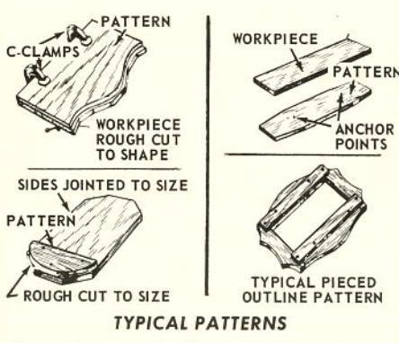
The pattern can be attached to the workpiece in several ways; but is must be anchored so that it will not slip when in use. Use nails, screws, clamps or anchor points, as shown. When identical edges are to be repeated on two more sides of a workpiece, a single pattern for one side can be prepared — and can be moved from side to side to complete the job.

The quickest way to make a pattern is to lay out the desired edge shape in pencil on the stock to be used for the pattern — then to cut out the pattern on a band or jig saw.
PATTERNS IN USE

In use, the edge of the pattern rides against a collar, against the fence, or against a suitable guide clamped to the table. The pattern can be designed to ride against the collar above or below the cutter. It won't matter if it is partially cut away during the work, so long as a sufficient edge remains for pressing against the collar.

DOUBLE PATTERNS
When a moulding is to be cut on a workpiece that is identical on two or more sides, it is sometimes an advantage to make two identical patterns and to sandwich the workpiece between them, as illustrated. This allows the work to be turned over at any time to favor the grain, or to aid in the cutting. Another advantage is that the work can often be held between the double patterns without nailing, screwing, or clamping — and will not slide out of place if sufficient down pressure is maintained during the operation.

PATTERNS AND FORMS
PLANNING A BEVEL
By using a pattern together with a straight cutter and either the fence, or a collar on the spindle, a workpiece edge can be planed on the shaper to any desired contour which the cutter can be made to follow.

If the indentations in the edge are too deep at one bite, pass work across cutter two or more times. By using two collars and a at the desired angle, as illustrated, a bevel edge (either plain or moulded) can be contour shaped, in the same manner. This method of beveling is particularly handy for creating a bevel which starts out at one end of the workpiece at one angle. and changes angle before reaching the other end. The pattern can be designed to twist the workpiece as it is fed past the cutter. to obtain this varied bevel effect. A narrow block must be fastened to the table adjacent to the cutter so that bottom of pattern will ride on the block. This provides a small contact surface on which the pattern can easily be twisted.
DOUBLING-UP PATTERNS
When long, narrow shapes are to be contour planed or edge moulded, and a number of identical pieces are to be made, a doublingup pattern affords both convenience and safety. Use of such a pattern keeps the hands well away from cutter. The two edges of the pattern are shaped like the two edges of each workpiece are to be shaped – but the pattern is twice or more the width of the workpiece. Two workpieces are mounted simultaneously, as illustrated –

and one edge (at opposite sides) of each is shaped or moulded. Then reverse their positions on the pattern — and shape the remaining edges.
The pattern illustrated uses bolts with wing nuts and clamping blocks to secure workpieces in place. Workpieces can also be held in the manner previously described.
TWO USEFUL SLIDING JIGS
Two typical homemade jigs, designed to slide in the miter gage groove, are illustrated below. One is designed to hold work vertically . is useful for face shaping. The other is used for holding work in various positions for edge shaping.
Typical uses for these jigs are illustrated. Although the jigs shown are designed to slide in the miter gage groove, it is sometimes advantageous to remove the guide bar from the under side of such a jig, and to use the jig to hold both a pattern and the workpiece for guiding against a collar, or a guide clamped to the table top.


STRIP SHAPING JIG
The above illustration shows a jig which will greatly facilitate strip shaping operations. This type of jig is particularly useful when shaping vork which is small, and consequently, rather flexible. Without the use of a jig, it is usually somewhat difficult to work with small stock since the work cannot be held rigid and guided properly during the shaping operation. Clamp the jig to the table of the shaper with C-clamps so that the cutter opening in the jig and the guide channel formed by the spring and jig guide strips is properly oriented in respect to the shaper cutter. Perform shaping operation by feeding the work through the guide channel of the jig.

A PIVOT JIG
A simple pivot jig makes it easy to shape and edge mould round or circular workpieces. Construction of the jig is illustrated above. The base is designed so that it can be clamped to the shaper table at any desired position — and the turntable is pivot mounted to the base so that it can be rotated in a true circle while supporting a workpiece placed on top of it.
If the work is a full circle (so that the work must be advanced into the cutter before it can be rotated), start the cut by shoving the jig and workpiece toward the cutter and up against a stop block which will limit the depth of cut as desired. After the cut is started, stop the machine and clamp the jig to the tables, before rotating the turntable to form the circular edge.
A ROUNDING JIG
This jig also consists of a turntable pivot mounted to a base which can be clamped to

the shaper table. In this case, however, the turntable is designed to hold square workpieces and has side guides against which the workpiece can be firmly positioned.
A TYPICAL HOLDING JIG

When an irregular shaped workpiece — such as an octagonal-shaped table leg or a cabriole chair leg — is to be finished with edge or face moulding designs, a specially made holding jig is required. The jig is built up from scrap wood so that it will properly support and securely hold the workpiece. If the workpiece is to be worked against a collar, the bottom part of the jig can have a pattern cut on one or both sides — and the entire jig serves not only to hold the workpiece, but also as a pattern guide. The jig can also be designed to slide against the shaper fence or in the miter gage groove of the table top. A typical holding jig is illustrated above.
A ROCKING JIG
The use of a crown block (page 18) for edge shaping of work that is curved in two directions has already been explained. Another method of handling these compound-curved workpieces is to use a rocking jig. A typical jig design is illustrated above. The jig is shaped to hold the curved workpiece — and the bottom piece of the jig is a pattern.

In use, the pattern edge of the jig is pressed against a collar, and the jig is rocked as the work is fed to the cutter, to keep the workpiece edge at a constant height above the table at point of contact with cutter.
A TENONING JIG

Round tenons at the ends of square workpieces can often be cut on the shaper quicker and more easily than on a lathe. A simple homemade jig and a wooden collar mounted on the spindle are needed.
The jig is set up as shown, with the wooden collar on the spindle underneath the cutter to limit the tenon length. The jig is a block of wood which holds a circular plug with a square center opening. Workpiece is inserted through the plug and revolved on a vertical axis. A thin piece of wood at bottom of block holds the plug in place. Work is fed slowly downward against the cutter until proper depth is reached; is then slowly revolved against the direction of cutter rotation to complete the tenon.
A BEVEL JIG
Bevel edging at any desired angle is quickly
and easily accomplished with an adjustable bevel jig like the one illustrated at bottom of page. This jig consists of a table hinge mounted to a wood block that can be bolted or clamped to the shaper table. A slight shoulder on the table provides a straightedge guide against which the workpiece can be slid for feeding to the cutter. The angle of the table with respect to the shaper table is determined by the guides (one at each end of the table) which can be clamped against the edge of the shaper table.
With the jig in place, a workpiece can be quickly planed or molded at any bevel angle. A workpiece with equal size faces (such as a hexagonal column) can be easily created out of round or square stock. It is only necessary to determine the angle between any two faces — then to set the jig to this angle and plane each face in turn to the finished size of the face. In order to determine the angle and width of the face, make a full-scale cross-sectional drawing of the finished column, then measure the faces with a ruler and the angles with a protractor.
A FLUTING JIG
This homemade jig has many useful purposes. The headstock holds a revolvable index head fitted with a shaft. This index head is drilled at rear end with a series of equally spaces small holes to divide a circle into 24 parts. Selected holes will therefore divide a circle into 2, 3, 4, 6, 8, or 12 parts. A nail inserted through a hole in the headstock will engage one of these holes to hold the index head stationary at a desired position. The tailstock is adjustable for different length workpieces.


The overall height of the jig centers must not exceed the height above the shaper table at which a cutter can be located on the spindle. The jig is used only as a holding device — and one edge of the base must be parallel with the centers so that the whole jig (with the workpiece on the centers) can be guided by a collar on the spindle or by a guide clamped to the shaper table. With the jig it is easy to make a column with an equal number of equal-size faces — with flutings — or with specially molded designs.
A RADIAL ROSETTE JIG
By using an index head (like one above) and a wood-block slide to hold this head at a right angle to the cutter, you can build a jig for quick production of radial rosettes at the end of a workpiece. The index head can be rotated in the slide and can be secured by a nail at various desired stop positions. The workpiece is clamped to the face of the index head — and the whole jig is positioned on the shaper table so that the slide will carry the workpiece past the revolving cutter. The axis of the index head and the horizontal center of the cutter must be the same height above the shaper table.

In use, the work is passed in front of the cutter at different positions of the index
head to produce a pattern on the end of the work. An inside-circle guide (page 17), positioned vertically can be used instead of the horizontal guide illustrated to hold the slide — then the work will be passed in front of the cutter on an arc, and the radial lines of the resulting rosette will have a spiral effect. If this type of guide is used, the lowest point of the guide must be in line with the vertical center line of the spindle.

SASH AND DOOR SHAPING
With the use of proper shaper cutters and collars, sash and door shaping operations can readily be performed with your shaper. A sash and door cutter kit consisting of a cutter, collars, etc., is available. Although standard sash and door stock is 1-3/8-inch material, and the collars of the sash and door cutter kit are designed specifically for working with standard 1-3/8-inch sash and door stock, stock of other thicknesses can be worked by combining the collars.
Figure (A) shows the shaping of one side of a door stile.
Figure (B) shows the set-up for shaping the second side of a door stile. In addition to the main shaper cutter, a 1/4-inch straight face cutter is used in combination with the standard cutter.
Figure (C) indicates the sash coping operation of a door-rail end. The second coping operation on the door-rail end is accomplished by turning the stock over. Figure (D) indicates set-up for shaping a window sash stile. This combination consists of the standard sash and door cutter together with a spacer of required thickness and a straight-face cutter to cut the glass rabbet. Figure (E) indicates the set-up for coping the window sash rail ends.

23
MISC. SHAPER OPERATIONS

JOINTING
Edge jointing is easily accomplished with a straight cutter and proper adjustment of the regular shaper fence. Position the rear face of the fence so that the workpiece, when pressed against it, will just touch the cutter. Now position the front face so that it is in back of the rear face by a distance equal to the amount of material that you desire to remove from the workpiece edge.
Very deep cuts should not be taken on the average workshop shaper; but such cuts can occasionally be made, if desired. Best practice is to take small cuts and make as many passes as necessary.
TAPER JOINTING
The set-up for taper jointing is the same as for jointing — except that the workpiece is started with the leading edge pressed against the rear face of the fence. This will hold the workpiece at an angle (as established by the positions of the rear and front faces), and — if the edge of the workpiece is held firmly against the front face as the work is advanced — will result in a taper. If a shaped cutter is used instead of a straight cutter, the edge can be moulded and tapered simultaneously.
Rip planing differs from regular planing and other shaper operations in that the workpiece is not only planed (or moulded) at the edge, but is also reduced to an exact size at the same time. This is easily accomplished on the shaper by use of an auxiliary guide fence — and by running the work between this guide fence and the cutter.
Because the workpiece is forced between the revolving cutter and the auxiliary fence, there is a tendency for the cutter to hog the work (that is, to dig in). For this reason, a hold-in must always be used when rip planing. This is positioned, as illustrated above, behind the cutter. It presses against the finished edge to push the work over against the auxiliary fence. Any scrap

board clamped to the table top can be used as a hold-in; or the regular shaper fence can be used. If the regular fence is used, back the front face away from the work so that only the rear face contacts the work to serve as a hold-in.
To position a hold-in, move the auxiliary fence over so that it just touches the cutter, then place the hold-in in contact with the auxiliary fence. Now move the auxiliary fence away from the cutter a distance exactly equal to the desired width of the finished workpiece.
Any type of moulded edge can be produced while rip planing. This is also a good method to use to produce a tapered workpiece to exact dimensions. If a taper is desired, simply place a tapering jig (see book No. 2926, The Circular Saw) between the auxiliary fence and the workpiece and set this ig to the desired angle.

PANEL RAISING
Panel raising is a very useful operation in the building of cabinet doors and the like a raised panel being simply a workpiece which is reduced in thickness on all edges to fit the groove of a frame built to surround it.
One method of panel raising is to use a small circular saw with a beveled edge in place of a cutter on the shaper spindle. As the saw blade will be perfectly horizontal, it is necessary to block the workpiece up at an angle under the saw blade to produce a taper at the reduced workpiece edge. A set-up is illustrated above.

A novel raised panel having a groove at the edge of the raised portion can be made by using a chipper from a dado head set. As the chipper is a straight blade, the work must be blocked up, the same as when using a saw blade. The chipper must be sharpened along both leading edges.
SHAPING FIGURES
It is sometimes necessary to make quantities of duplicate alphabet letters or other small design pieces for use in decorations or for games. An easy way to do this is to cut the design into a long strip of wood, using your shaper cutter. Afterwards, you can cut the strip up into many parts with a saw - and the resulting flat figures will all be identical.


MAKING DOWELS
Perfect dowels can be cut on your shaper by using either of two methods. Both methods require considerable care in mak-

ing an exact set-up so that cuts taken by the cutter will match perfectly to produce a perfect circle. This, however, is merely a matter of taking the time to set the cutter at the right height, and the fence at the right depth of cut.
The first method is to take four corner cuts on a piece of square stock — the four cuts each being exactly 1/4 of a circle, and meeting exactly to complete the circle. The second method is to take only two cuts, each being a semicircle. If the dowel being produced is large enough, the workpiece can be fed freehand — but a guide, such as used for strip mouldings (page 21) should be set-up when cutting small diameter dowels.
ORNAMENTAL DESIGNS
By using different patterns, cutter shapes, and arrangements you will be able to produce many hundreds of different ornamental designs with your shaper. It would be impossible in this small book to illustrate and describe in detail all such possible designs — but two typical ornamentations are illustrated.


The first is easily produced by using a waved edge pattern which will vary the depth of cut as the work is pushed past the cutter, and - in this case - by using a cutter smaller than the thickness of the workpiece. The second design is produced by making a series of "staged" cuts. instead of a continuous long cut on the workpiece. The "staging" of the cuts is obtained by using a notched pattern and a stationary pin clamped to the table. The notches are engaged over the pin, one after another, to hold the workpiece at fixed positions with respect to the cutter. In the case illustrated, the cutter selected has produced cylindrical, straight sided cuts in the edge of the workpiece - and the pattern notches and pin have been used to space these notches at equal intervals along the workpiece edge. Each cut is made by pushing the workpiece into the cutter up against a collar which limits the depth of cut - and by then backing it off of the cutter and moving it along to the next pattern notch to repeat the process. Unequal spacing of the cuts can be used if desired — and two or three rows of cuts at different heights in the workpiece edge can also be used.
THE MOLDING CUTTER HEAD


IVE TONGUE & GROOV

SETTING UP THE CUTTER HEAD
A molding cutter head will hold the blades shown, or homemade blades of your own design. Mount the head on the spindle with the flat sides of the cutter blades facing the direction of spindle rotation. Your shaper fence will not open wide enough to clear the not over 1 inch of the head should be exposed — and the fence should encircle the head to a depth of 5 inches. You can bolt wooden extensions onto your fence faces to adapt it. Each extension should be 4-1/2 in shorter than the fence face by 1-5/8 in. Mount the two extensions flush with the outer edges of the fence faces (they will be stepedges). Now when the faces are fully senarated (3 in. between original faces), there - and these will surround the cutter head to
Regulating Speed
The larger cutter head will have an excessive foot per minute speed at the ends of the cutter blades unless you reduce the spindle speed. It is advisable to use a motor pulley that is 1/2 the diameter of your regular motor pulley.
INSTALLING DIFFERENT CUTTER
Different blade sets can be installed without removing the cutter head. Change one blade at a time. Be sure that the cutter-head slots are clean so that the blades fit all the way down in them — and extend out exactly the same distance.
MAKING YOUR OWN BLADE SHAPES
Purchase Planer Blades, which have straight edges. Re-grind these edges to the desired shape — making all three exactly the same shape, and the same length. Bevel all edges at a 15° angle for clearance. Be careful not to draw the temper from the blades when grinding (either use a whetstone, or air cool them frequently). Finish the blades by honing them carefully (flat sides against stone) to sharpen them.
SELECTING PATTERNS

Use 4-inch squares of vellum or tracing paper and keep a record of each different blade shape. Two or more papers can then be stacked together and shifted about so that, when you look through them, you can see the result of different blade arrangements.
THE BENCH SANDER

COMBINATION 6-IN. BELT, 9-IN. DISC BENCH SANDER
ADVANTAGES OF A BENCH SANDER
Hand sanding is one of the most tedious of woodworking chores. The substitution of electrical power for muscle not only speeds sanding and eliminates fatigue . it also produces much finer, more uniform work with a saving in sandpaper costs (power-driven abrasives last longer). For large workpieces, heavy enough to remain firmly in position, an electrically powered hand sander generally is preferable; but for small pieces which must be steadied by holding, a bench sander is the only practical solution.
With Sears Bench Sander illustrated you can quickly rough sand to shape, can do fitting of pieces (as for inlay work), can finish sand almost any shape of workpiece with precision, and can do the fine sanding required when building up an exquisite, high-gloss finish.
SELECTING YOUR BENCH SANDER
Both a belt and a disc are necessary for complete versatility. A disc is excellent for quick roughing to shape and for convex (outside) contour sanding of smaller pieces; but a disc has the disadvantage of sanding faster at its outer edge (which travels
faster) than at its center ... thus making it difficult to sand a true straightedge of any length more than a couple of inches. On the other hand, a belt is excellent for true straightedge sanding, for surface sanding and for concave (inside) contour sanding of radii into which the belt drum ends will fit . but is "more tool" than needed when a disc will do the job.
A tilting table (45° to 90°.. such as shown) — which can be positioned for use with either the disc or the belt — makes it possible to hold work steady at proper angle to the abrasive surface. The adjustability of the belt — from horizontal to vertical position — further enhances the ease with which work can be positioned as desired. Use of a table miter gauge (when disc sanding) or of a belt fence (when belt sanding) makes it possible to slide work firmly and accurately across the abrasive surface at angle desired. Without these features it is impractical to do fast, accurate work.
Other desirable features incorporated in Sears tools are: A belt aligning and tensioning adjustment that is simple and fast. A firm-locking adjustment for belt tilt, from 0° (horizontal) up to 90° (vertical). Lifetime, sealed ball bearings in belt drums. A miter gage – adjustable from 45° to 90° – which may be separately purchased for use on tilting table.
SANDER ADJUSTMENTS
MOUNTING YOUR BENCH SANDER
Your sander can be mounted on a firm bench at convenient height, but for greater convenience we recommend either a pedestal stand (such as on page 3 ) or a movable steel bench. The proper stand or bench is available at Sears. Bolt sander in place with motor below it on a motor rail, arranged to keep constant belt tension. Use a min. 1/2 hp (preferably a 3/4 hp), 3450 rpm motor with a 2 inch pulley.
DIRECTION OF ROTATION
The belt must rotate so that the top surface travels toward the fence. When this is so, disc will rotate counterclockwise.
ADJUSTING THE TILTING TABLE
The end-to-end horizontal position of this table is established by the flat on its supporting rod. Whenever table is secured to this rod and rod is positioned in tool (in front of disk or belt), table will necessarily be upright.
Adjustable stops fix the 45° and 90° (horizontal) positions of the table, when the Table Tilt Lock Knoh is loosened so table can be moved to one or the other of these positions. If correction of stop positions is necessary, loosen the lock knob. First use a good square to position table exactly at 90° to the disk (or belt), then retighten the lock knob. Now loosen the hex put on the square-head screw at back side of table support arm - then adjust the screw until it just contacts the rib on underside of This establishes the 90° position. Next. do the same for the 45° stop position, setting table at an accurate 45° to the disk (or belt), and adjusting the square-head screw that is on front side of table support

For in-between angle settings of the table use a protractor set at the angle desired. Loosen the lock knob, pull table carefully up to the angle established by the protractor — then retighten the knob.
ALIGNING AND TENSIONING BELT
These two operations are accomplished simultaneously. Loosen the two Belt Control Lock Knobs and turn on the power. Use both hands to rotate the two Belt Control Knobs as required both to tension the belt and to make it track perfectly on its drums. Finger pressure on the knobs will provide sufficient tension. Too much tension is unnecessary and undesirable. With belt running true and properly tensioned, tighten the two Belt Control Lock Knobs securely. If it is not to be used for some time, best leave belt untensioned.
POSITIONING BELT TABLE
The table, over which the belt travels, may be positioned at any angle from 0o (horizontal) to 90o (vertical). Various operations require different table positions. To set, simply loosen the two Belt Table Pivot Lock Bolts, position table as desired . then retighten the bolts. Permanent stops fix the 0o and 90o angles. For other angles, install the tilting table in front of the belt, then use a protractor as illustrated.

ADJUSTING BELT FENCE
To adjust, loosen the bolt that holds fence . then use a square as illustrated. Retighten the bolt.
SETTING MITER-GAGE PROTRACTOR
Use a square to check the 900 setting of the miter-gage protractor. Loosen the screw and position the arrow to read 900.
BELT SANDING OPERATIONS
BELT SELECTION - AND CHANGING
Belts are available in fine, medium and coarse grits. The medium is best for all general shop work. Use the coarse grit only when rough sanding to quickly size or shape a piece; use the fine grit only for finish sanding or sanding between coats of paint, etc. To change belts, loosen the belt tension sufficiently to slide the old one off and the new one onto the pulleys... then realign and retension the new belt.
SURFACING OPERATIONS
All surface sanding should be done with the belt horizontal.
If workpiece is shorter than belt, use the fence. Position work end against fence, use one hand to lightly press work onto belt and to hold it stationary . then start the sander and sand until right amount of stock has been removed. Stop the sander to remove the workpiece.
If workpiece is longer - but less than twice the length of the belt - do as above to each end separately. However, if work is more than twice belt length, the fence must be removed . and the work must be traveled in uniform manner lengthwise along the belt until entire surface has been sanded. In this case guide with one hand at board end not in contact with the belt, while using other hand to press lightly down on top over the part in contact with belt. When workpiece is long enough to sag at free end use a sawhorse or bench of proper height to support end and keep work exactly level. If allowed to sag, irregular work will result.
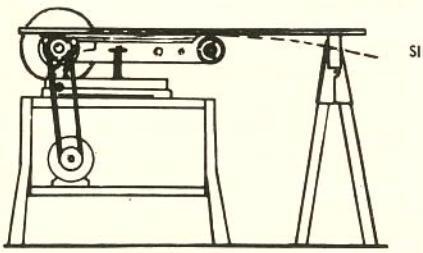
Always sand with the grain insofar as possible. If work is narrower than belt, hold it straight with belt travel; if wider than belt, slant it slightly so full width will be sanded as it moves over belt. Try to
avoid sanding side-by-side areas separately as this may leave a groove down center between areas. Never allow sides to overhang belt in one position . or belt edges will leave grooves.

Sanding is easy to do well. Just remember to let the tool do the work . don't try to "pressure it" yourself or you'll obtain uneven, grainy results. Above all, keep your hands away from the moving belt or disc . and don't wear any loose, floppy clothes (sleeves or a tie) to be caught up by the moving parts.
EDGE SANDING
Edge sanding is done with the belt fence (for short work) or without it (by traveling the work) much the same as surfacing is done. To keep the edge at 90o (or any desired bevel angle) with the faces, board must be held exactly upright (or at proper angle). A simple set-up can be arranged by clamping suitable boards to each side of workpiece ... to be sanded with it. Or you can make and use a side fence ( pg. 30 ).

Short boards can be end sanded in the manner illustrated, at 90° to board faces. However, if board is too long too hold it steady — or if any angle other than 90° is desired — the tilting table must be used ( pg. 30 ).
USE OF TILTING TABLE
All edge or end sanding - at 90° or any angle desired - can be done with the belt vertical and with the work placed on the tilting table. Angle between tilting table and belt table then determines bevel angle of work edge to work faces. To sand a taper angle (or a compound taper and bevel angle) use the miter gage in the table groove to guide work at the desired angle. Always hold work firmly down on table, sliding it across belt as necessary.

An inside curve can be sanded on the drum at end of belt, as shown. Position the belt table for maximum convenience. Sand with the grain insofar as possible.
Various shape forms can be made to fit and to tract so as not to run off of pulleys. If slackened belt won't cover form, an oversize belt is required. If form has irto mold itself to the form ... preferably

1/4" TOILET-BOWL BOLTS
18 x 3" FENCE =
UPRICHTS -
DRILL AND TAP FOR "" BOLT
HOW TO MAKE A SIDE FENCE
As there are no stops, this by using a square or a protractor to gage the angle surface. After setting. tighten the wing nuts securely to hold fence in nosition
Many belt sanding operations can be made easier by use of a side fence. A homemade fence is illustrated. Use 1-in. hardwood for the fence, beveling the bottom edge at 60° to leave a knife-edge at face side of fence. Groove the face horizontally. Embed
the studs (toilet-bowl bolts) as close to rear inum bar stock for the uprights making slots 1/4 x 1-in, with tops 2-7/8-in, above belt. Drill and tap belt-table side (opposite disc) to secure the uprights.
GRIT SELECTION - AND CHANGING
Sandpaper discs are available in fine, medium and coarse grits. To remove a disc. soak plate in hot water. Dry plate thoroughly. Cement new disc to plate face using either Disc or Pressure Sensitive Cement. If you need two or more of the grits, we recommend purchasing extra steel discs.
A DUAL-PURPOSE DISC
Two grits can be cemented to one plate with finer grit inlaid at center of coarser grit, as shown. Do coarser sanding at disc edge: move to center for finer sanding. This speeds production-type work.
HOW TO USE DISC
Best do all disc sanding with work pressed firmly down on tilting table - and feeding If work extends across "up" disc side, hold this portion down with extra firmness. The tilt of the table and the miter-gage angling may be used to obtain bevel, tapered
USING A PATTERN
Production of many identical pieces is best done with a pattern, as above. The base is a piece of wood to fit tilting table with a thin metal guide fastened to inside edge and projecting up for pattern to ride against. Fasten a strip to underside of base to fit into miter-gage slot so that guide is almost touching disc. Make pattern guide and disc.
A THICKNESS SIZING UG
A set-up such as illustrated will ensure uniform thickness sanding of any workpiece . if backside of workpiece is finished LOCKING SCREW first to provide a smooth contact with
the guide. DUAL-GR T DISC SING PATTERN
DISC SANDING - USE OF JIGS
A SEGMENT PIVOT JIG
For accurate curvature sanding some type of jig is needed. A simple one for segment work is shown. Use a base like one above to hold a pin (dowel peg) for the Y-arm to nivot on. Drive nails through Y ends to project on underside sufficiently to bite into. and hold, the workpiece. Make the set-up so that just right amount will be sanded off workpiece when it is pivoted across the

For full circle sanding a jig as shown is best The base is made like ones above but has a dovetail groove at down side of disc to hold bevel-edged slide. Slide can be wood, but a 1/4 x 1-in, aluminum bar is better. A nail or sharpened screw noint serves as the nivot point. The locking screw wedges the slide in its groove to hold it stationary. Start with work centered on pivot point . move slide up until work is sanded in to desired radius . then lock the slide and revolve the workpiece to shape entire contour


DISC SANDING

SLACK-BELT SANDING
Slackening the belt - then sanding on the
backside of the belt table with the table
vertical as shown - will allow the belt to
mold itself around a convex curve that is
not too abrupt. This helps to avoid flats
created by oversanding at some points, since
more of the belt is constantly in contact
with the work. Loosen the belt just enough
so that pressure of work against it will
slip or buckle. For wide, irregular sur-
faces a slashed belt will mold to work
contour even better.
USING BUILT-UP FORMS -


 Loading...