


Part No. 9504070
IMPORTANT
rules for safe operation
WEAR PROTECTIVE ATTIRE
Always wear welding goggles to protect eyes from sparks and light rays. Use gloves. Watch for sparks in cuffs.
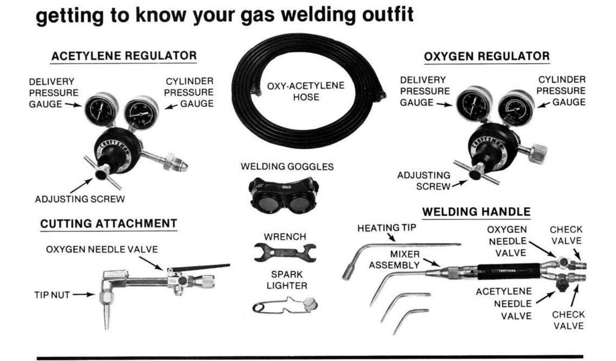
HANDLE CYLINDERS WITH CARE
Chain or otherwise secure cylinders to permanent fixture. Take care when moving. Never use an acetylene cylinder in other than upright position.
USE "GOOD HOUSEKEEPING" IN WORK AREAS
Keep sparks and flame away from combustibles. Prepare your area before welding or cutting. Work in well ventilated area.
BE SURE ALL CONNECTIONS ARE TIGHT
Never test for a leak with an open flame. Use a soap-water solution instead. Don't force connections.
USE RECOMMENDED PRESSURE SETTINGS
Improper pressures are wasteful. Extreme pressure buildup in regulators is a warning they need repair.
NEVER USE OXYGEN TO BLOW OFF WORK OR CLOTHING
Pure oxygen supports combustion and a spark can ignite oxygen-saturated clothing.
DO NOT USE OIL OR GREASE ON THE EQUIPMENT
The equipment does not require lubrication. Oil or grease is easily ignited and burns violently in the presence of oxygen under pressure.
"CRACK" OXYGEN CYLINDER VALVE BEFORE INSTALLING REGULATOR
Open valve slightly and then close. (Make sure to keep away from sparks or open flame.) This will clear valve of dust or dirt which may be carried into the regulator and cause damage or accident.
PURGE OXYGEN AND FUEL GAS PASSAGES SEPARATELY BEFORE LIGHTING UP
This will aid in preventing improper mixing of gases.
PURGE SYSTEM AFTER USE
When shutting down, close cylinder valves, and then bleed system by emptying both hoses independently. First, open the oxygen needle valve, drain line until pressure is zero, then close oxygen needle valve. Repeat process with acetylene needle valve.
DO NOT WORK WITH DAMAGED OR LEAKING EQUIPMENT
Use soapy water when checking for leaks. Do not use frayed or damaged hose. Never use torch as a hammer or to knock slag from work.
USE GENUINE WELDING AND CUTTING TIPS AND REPLACEMENT PARTS
If unit requires repair parts other than those listed in parts list, unit should be returned to Sears for repair.
IT IS RECOMMENDED THAT YOU OBTAIN AND READ OTHER SAFETY INFORMATION FROM:
Publication No. 78-138. "Safety and Health in Arc Welding and Gas Welding and Cutting". National Institute for Occupational Safety and Health 4676 Columbia Parkway Cincinnati, OH 45226
AWS C-4.2-78 Operator Manual for Oxy-fuel Gas Cutting American Welding Society 2501 Northwest 7th Street Miami, FL 33125
ANSI Z49.1 Safety in Welding and Cutting American National Standards Institute 1430 Broadway, New York, NY 10018
READ THIS BOOKLET THOROUGHLY AND FOLLOW INSTRUCTIONS.

index
| p | age |
|---|---|
| ules for safe operation | 2 |
| uarantee & safety instructions | 3 |
| et-up | -5-6 |
| ighting, adjusting & shutdown | -8-9 |
| leating | 10 |
| velding | 11 |
| prazing | 12 |
| utting | 13 |
| rouble shooting | 14 |
| epair parts | 15 |
this manual is designed to make it as easy as possible to safely set up, maintain and operate your new gas welding outfit

The operation of any Welding and Cutting Outfit can result in foreign objects being thrown into the eyes, which can result in severe eye damage. Always wear safety
glasses or eye shields before commencing welding or cutting operations. We recommend Wide Vision Safety Mask for over spectacles or standard safety glasses, available at Sears Retail or Catalog Stores.
FLASH-GUARD® CHECK VALVES
Your Sears Craftsman heating, cutting and welding torch is factory equipped with reverse flow check valves. These valves are designed to prevent accidental mixing of oxygen and acetylene in hoses, regulators or gas cylinders. These valves fully open at 4 oz. of positive pressure and are factory tested to close completely at 10 oz. of reverse pressure. See page 14 for periodic inspection procedure.

how to hook up your gas welding outfit
SECURE CYLINDERS
Chain cylinders securely to cylinder truck, wall or post so that they cannot tip or fall. Both cylinders should always be used in a vertical position —never lying on their sides.
Crack Oxygen cylinder valve to blow out any foreign material that may have become lodged in it. "Cracking Valve" means to open valve slightly allowing just enough oxygen to escape to blow out the inlet passage of the valve. Then close valve immediately.
CRACKING CYLINDER VALVE

ATTACHING OXYGEN REGULATOR
Attach oxygen regulator with wrench furnished in kit. Don't force connections. If regulator connection leaks after reasonable force is applied, remove regulator and inspect both regulator connection and mating seat of cylinder valve. If cylinder seat is nicked, return cylinder to supplier. If regulator inlet is nicked, return unit to Sears for repair. USE NO OIL OR GREASE UNDER ANY CONDITIONS.
Attach acetylene regulator using the same procedure as described in instruction above. CAUTION: The same safety information given in instruction above also ap-
plies to the acetylene regulator.

ATTACHING ACETYLENE REGULATOR

ATTACHING HOSES TO REGULATORS

Red acetylene hose and regulator have lefthand threads. Green oxygen hose and regulator have right-hand threads.
RELEASING REGULATOR ADJUSTING SCREWS
The adjusting screws on both regulators should be released to take all spring pressure off of the diaphragms. This is done by turning the adjusting screw with a counter clockwise movement until it moves freely without binding. When regulators are not in use adjusting screws should always be released. This helps prevent abuse and fatigue of diaphragms.

CONNECTING HOSES TO TORCH

Match red acetylene hose to lefthand torch inlet threads marked "Gas," and red acetylene needle valve. Repeat process with righthand threaded oxygen hose, torch inlet marked "Oxygen," and green needle valve.
SELECTING WELDING AND CUTTING TIPS

Consult pressure charts shown on pages 10, 11, and 13 and select the tip which is the correct size for the metal thickness to be welded or cut. Note which gas pressures are recommended for that tip size. Inspect the tip to make sure it is clean. Tighten the cutting tip with the torch wrench furnished in kit. Heating and welding tips should be tightened with hand tight pressure only.
SETTING GAS PRESSURES
Unwind adjusting screws until they move freely without binding. Open cylinder valves slowly. Wind in adjusting screw until desired pressure is reached. This is shown on the low pressure gauge of each regulator. The high pressure guage indicates how much pressure is in the cylinder. Proper pressures are shown on the tip charts on pages 10, 11, and 13 .

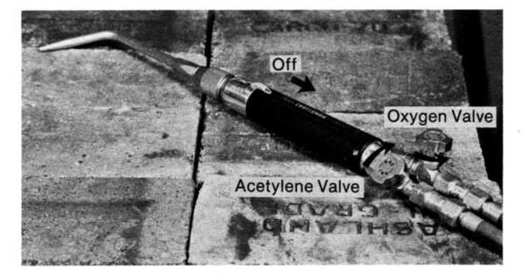
how to light/adjust pilot and torch
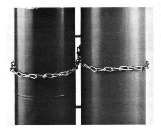
READY TORCH FOR LIGHTING
Roll On/Off thumbwheel forward (toward tip end) to
"ON" position.
LIGHTING THE TORCH

ADJUSTING THE NEUTRAL FLAME
When correct acetylene flame is obtained, open oxygen needle valve and adjust a neutral flame as in photo. Do not readjust with acetylene needle valve to obtain a sharper flame. A proper flame need not have a sharp inner tip.
Open acetylene needle valve and light acetylene at tip end. Correct acetylene flame is sufficiently large to eli-
minate carbon or soot in the air.
An excessive acetylene flame produces a lengthened inner cone or "feather". An excessive oxygen flame has a pale color, is likely to pop out and affects weld quality.

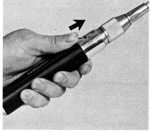
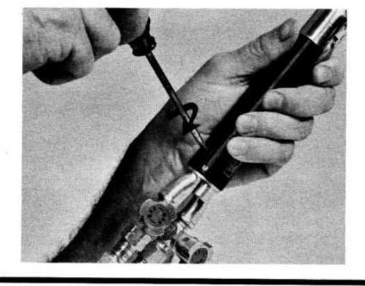
ADJUSTING THE PILOT
This unit is equipped with the pilot adjusting screw in the "OFF" position. With a small screwdriver, turn pilot adjusting screw counter clockwise ¼ turn. Then slowly roll thumbwheel to "OFF" position. Adjust screw slightly to get pilot light as shown in picture below. There should be no black sooty flame, nor should pilot be so small that it can be extinguished by waving torch gently from side to side.
If pilot flame does not appear, then:
- the screw may have been opened too far, blowing pilot light out,
- the screw may be open too little, permitting too little gas flow, or
- the thumbwheel may have been rolled too quickly to "OFF" position.
If pilot light flame does not appear, repeat above procedure.

THE TORCH SETTING NEEDS THE ADJUSTMENT ONLY ONCE.
FULL FLAME PILOT USE
Now that pilot is set, torch may be laid down on any non-flammable metal surface or hung on a hanger when not in use. Do not ever place lit pilot torch near any surface or material that might ignite or cause a fire. The recommended surface for the "at rest" position is that of firebricks or a hanger that angles lit flame away from work area or other employees and aisles.

equipment shutdown
- 1. With pilot light on (thumbwheel in "OFF" position), turn off oxygen (green valve) torch valve.
- 2. Turn off acetylene (red valve) torch valve.
- Do not turn pilot screw as it is set for future use. Pilot screw needs no further adjustment unless cutting attachment or heating tip are to be used.
HOW TO SHUT DOWN EQUIPMENT
equipment relighting
HOW TO RELIGHT TORCH
- At beginning of day, follow above procedure for lighting; except after initial pilot setting is made, no further adjustment needed.
-
If pilot "Off" option is chosen, light as follows:
a) Check pilot screw to be certain it is off (turn clockwise).
- b) Light torch as described above.
- c) Turn thumbwheel off slowly. Torch flame will change to orange and then go out.
To relight:
- a) Roll thumbwheel forward half-way.
- b) Ignite gas (orange flame).
- c) Roll thumbwheel forward all the way. Flame is ready. No needle valve adjustment at torch necessary.
- CAUTION: Never turn thumbwheel to "ON" position without lighting equipment immediately.
USING HEATING TIP AND CUTTING ATTACHMENT
It is recommended pilot be in "OFF" position only. Be sure to check that pilot adjusting screw is off before using heating or cutting attachment, by turning screw clockwise to "OFF" position.
LIGHTING THE HEATING TIP
After turning pilot adjusting screw "OFF", roll thumbwheel to "ON" position. Then open acetylene valve and light at tip end. When correct acetylene flame is reached, open oxygen valve and adjust to neutral flame. To extinguish flame, roll thumbwheel to "OFF" position. To relight, repeat above procedure.

NEUTRAL HEATING FLAME

heating
Heating is a very easy technique to learn, and is among the most useful operations performed with a combination outfit.
It may be used to provide quick even heating of a broad surface area prior to bending. It may also be used to work metals into different shapes and is ideal for automotive work. Because the flame is 6000 deg. F, the flame should not be directed at a fixed spot for any length of time to avoid melting or burning a hole in thin material.
After the heating flame has been adjusted, keep the point of the flame about 3/16" away from the work surface for maximum heat, weaving it ever so slightly. For thinner materials, such as auto bodies, keep flame 3-5 inches from work to avoid burnthrough. Do not advance until the spot becomes cherry red (about 1200 deg. F). Continue heating the desired area, maintaining the cherry red color before moving on until the job is complete. The heat must be continuous to get full benefit.

PRESSURE CHART FOR HEATING TIP
| Tip | Tip |
Oxygen
Pressure |
Acetylene
Pressure |
Heat Output
BTUs/hour |
Oxygen
Flow |
Acetylene
Flow |
|---|---|---|---|---|---|---|
| No. | Size | PSI* | PSI* | #1 Tip | Cubic F | eet/Hour |
| 54439 | #1 | 2-6 | 2-6 | 29,500-51,500 | 22-38 | 20-35 |
Maximum pressure is neutral flame with no flame blow-off. Minimum pressure is neutral flame with no flame pop-out.
Useful heat input to work will vary widely and may be considerably less than tip output.
*Both regulators should be set to the same pressure within this range. Example: a 3 PSI acetylene setting requires a 3 PSI oxygen setting.
basic welding operations / ferrous metal welding
Gas Welding is a method of joining steel by heating the surfaces to the melting point with an oxy-acetylene flame, and allowing the two parts to fuse together. Filler metal is required on material 1/16" thick or more, and the resulting weld is as strong as the parent metal. All steel should be cleaned before welding. Oil, grease, rust, scale or other impurities affect the weld quality, or tensile strength. Steel 3/16" or more thick should be beveled before welding, and when beveled sides are joined a filler rod is necessary.

Gas welding is not a difficult art. The following exercises of torch movement are good practice, and make subsequent welding easy.
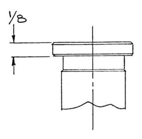
Take a small welding tip, and set proper pressures (see tip chart below). Point the flame directly onto the steel, 1/8" stock recommended, with the flame cone just above the metal surface. When a puddle is formed move the torch back and forth, and move the puddle across the steel. Do this slowly. It is necessary to have good penetration, and this comes from a deep puddle. When moving the puddle it is helpful to lean the top about 45° away from the direction you want the puddle to move.
Place two pieces of 1/8" steel together as shown in Figure 2. Make the puddle again, and with back and forth torch motions move the puddle along the seam. Go slowly to get good penetration. This can be checked by turning the parts over. The penetration should be visible from the bottom side. Test the weld strength by attempting to tear the parts apart.
Repeat exercise 2, but add welding rod this time. While the flames are directed at the steel in order to form the puddle, put the rod into the flame. When it gets red maintain this temperature by moving it in and out of the flame. Once the weld is started, dip the rod into the puddle. This builds up the weld so that the top is rounded instead of concave as when no rod was used. Remember, welding rod is necessary on all beveled joints, and once the welder is experienced he will prefer to use rod on all welds, regardless of how thin the steel.
Material 3/16" or thicker should be beveled before welding. A 30° bevel on each piece is best. This is necessary in order to obtain good penetration throughout the intire thickness. A rod is necessary filler material on all welds made from beveled edges.
Once torch movement and puddle are mastered, the welder has a tool that will repay its cost many times over.

Figure 1

Figure 2

Figure 3
|
Metal Thickness
(Inches) |
Tip Number | Tip Size |
Size of
Welding Rod |
Oxygen PSI |
Acetylene
Pressure |
|---|---|---|---|---|---|
| 1/32 | 1600425 | No. 1 | 1/16″ | 5* | 5 |
| 3/64 | 1600426 | No. 2 | 1/16″ | 5* | 5 |
| 1/16 | 1600404 | No. 3 | 1/16″ | 5* | 5 |
| 3/32 | 1600427 | No. 4 | 3/32″ | 5* | 5 |
| 1/8 | 1600405 | No. 5 | 3/32″ | 5* | 5 |
| 3/16 | 1600428 | No. 6 | 3/32″ | 6 | 6 |
| 1/4 | 1600406 | No. 7 | 1/8″ | 7 | 7 |
| 5/16 | 1600429 | No. 8 | 5/32″ | 8 | 8 |
PRESSURE CHART FOR WELDING TIPS
*5 PSI pressure setting is first white dot on low pressure oxygen gauge.
Industry safety standards require gauges to have 50% safety factor over maximum delivery pressure of regulator.
brazing
Braze Welding differs from steel welding because the two pieces of metal are not fused together. The brazing rod melts at a lower temperature than the parent metal, and the braze strength comes from the surface overlay of the brazing rod.
The advantage of Braze Welding over Steel Welding is this is the best way to join different metals, or repair cast iron. For instance, Braze Welding is the correct way to fix a pump water jacket. Almost any two metals can be joined, except Aluminum and Magnesium.

Braze welding is separated into two types depending on the type of rod used. Bronze is less expensive than silver, and should be used when the fit between the two metals to be joined is not close. The metals must be well cleaned. Then the flame is played onto them until they become a dull red color. Both pieces must be of equal temperature or the rod will flow to the hotter piece. Heat the rod by placing it in the flame. Then dip into the flux can. Notice the heat causes the flux to stick to the rod. If a prefluxed rod is used this heating and dipping step may be eliminated. Once the rod is fluxed, the metals brought to proper temperature, touch the rod to the joint, put the flame on the rod, and melt it. The rod then melts and flows over the heated area bonding the metal together. Abundant flux must be used. Without enough flux the rod does not "stick" to the metals.
Silver brazing is a little faster than bronze brazing. This is because silver melts at a lower temperature, and less heat is required. However, the joint must fit tightly together. Bronze bridges a gap much better than silver. Instead of putting flux on the silver rod, the joint should be painted with the flux. The way to determine when the metals are of proper temperature is to watch the flux. When it bubbles it is time to apply the silver. The silver melts as it is touched to the seam, and freely flows over the fluxed area.
cutting
Flame cutting is a simple process that can be quickly mastered. Only steel can be cut with the oxy-acetylene method. Cast iron, stainless steel, aluminum, brass and other non-ferrous metals do not "burn" the way steel does.
The way to cut steel is to heat it to its kindling temperature (a red color), and then burn it rapidly with pure oxygen. A cutting torch provides both the preheat flames, and pure cutting oxygen stream. Acetylene and oxygen are combined in the torch head, and burn at the torch tip with a 6000° F. flame. These are the preheat flames. The center hole in the cutting tip is the cutting oxygen hole. This is pure oxygen which is not mixed with acetylene. This cuts the steel after the metal is sufficiently preheated.
Propane or MAPP® gas may be used in place of acetylene by replacing the oxy-acetylene cutting tip with the appropriate tip for the gas being used. See "Pressure Chart for Cutting Tips" for proper tip.
Once the correct tip is tightly secured in the cutting torch, proper pressures set on the regulators, and neutral flame adjusted, follow these procedures to flame cut.
- Turn pilot adjusting screw clockwise (R) to "OFF" position.
- 2 Before lighting, open oxygen needle valve on torch handle one full turn. Make all oxygen adjustments with needle valve on cutting attachment.
- 3 Move the flame to the edge of the steel with the preheat cones just above the metal.
- When the steel becomes red, slowly press the cutting oxygen lever until the cutting jet cuts through the steel.
- 5 Then slowly move the torch in the direction of the cut. The correct cutting speed is accompanied by a sputtering sound, and a steady stream of sparks. This results in a clean, slag-free cut, with square top and bottom edges.
- 6 Too fast movement does not allow enough time for the oxygen jet to go all the way through the metal. Slag fills the kerf, and the two pieces are not severed.
- 7 Too slow movement leaves a rounded top edge with slag sticking to the bottom of the metal.
- B The size of the preheat flames determine how quickly the cut can be started. Often a small preheat is desirable. This type conserves gases, and does not cause melting of the top edges.
PRESSURE CHART FOR CUTTING TIPS
CAUTION: When cutting heavier steel (4" through 6") more operator skill is needed than with lesser thicknesses. Heavy leather gloves are needed to protect the worker from the heat. Cutting speeds are slower. 6" steel can be cut by a skilled operator with the 1500846 #4 tip at 100 PSI oxygen pressure, 9 PSI acetylene pressure, and 4" per minute cutting speed.
NOTE: The new improved cutting attachment in this outfit uses the 5/16" broadshouldered tip only.
|
Plate
Thickness (Inches) |
Tip
Number |
Tip
Size |
Oxygen
Pressure |
Acetylene
Pressure |
|---|---|---|---|---|
| ₩-₩ | 1500843 | #0 | 30-40 | 5-15 |
| %-1 | 1500841 | #1 | 35-50 | 5-15 |
| 1-2 | 1500844 | #2 | 40-55 | 5-15 |
| 2-3 | 1500845 | #3 | 45-60 | 5-15 |
| 3-6 | 1500846 | #4 | 50-100 | 5-15 |


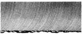
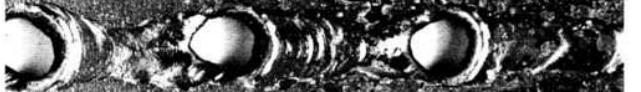
PERFECT CUT
Shows regular surface with slightly sloping drag lines. Surface can be used for many purposes without machining.
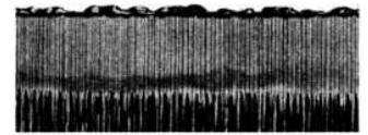
EXTREMELY FAST
Not enough time is allowed for slag to blow out of the kerf. Cut face is often slightly concave.
EXTREMELY SLOW
Produces pressure marks which indicate too much oxygen for cutting conditions.

TOO HOT PREHEAT
Rounded top edge caused by too much preheat. Excess preheat does not increase cutting speed. It only wastes gases.
|
Plate
Thickness (Inches) |
Tip
Number |
Tip
Size |
Oxygen
Pressure |
Propane
L/P Pressure |
|---|---|---|---|---|
|
%-1
1-3 |
1501230
1501250 |
#1
#3 |
35-50
45-60 |
5-15
5-15 |
|
Plate
Thickness (Inches) |
Tip
Number |
Tip
Size |
Oxygen
Pressure |
MAPP *
Pressure |
| %-1 | 1501560 | #1 | 35-50 | 5-15 |
trouble shooting
| TROUBLE SHOOTING CHART | ||||||||
|---|---|---|---|---|---|---|---|---|
| TROUBLE | PROBABLE CAUSE | REMEDY | ||||||
| Welding Tip popping |
|
|
||||||
| Backfire | Gas flows too low |
|
||||||
| Flames not clearly defined, smooth or even | Dirty tip |
Clean with tip cleaner or
replace tip |
||||||
|
Regulator not holding constant
pressure |
Defective seat |
|
||||||
| Cutting Tip popping |
|
|
||||||
| Leak around needle valve | Packing nut loose | Snug packing nut | ||||||
| Difficult to light | Too much pressure | Consult appropriate tip chart | ||||||
| Flame change when cutting |
|
|
||||||
| Heating tip popping |
|
|
||||||
|
Torch pilot light blow off
or sooty pilot flame |
|
|
||||||
| No pilot light | Adjusting screw closed | Open adjusting screw 1/4 turn | ||||||
| On/Off thumbwheel "pops" when turned off |
Thumbwheel rolled to
"OFF" too quickly |
Relight torch and move
thumbwheel more slowly |
||||||
check valve inspection procedure
Check valves are mechanical devices which can leak when abused or dirty. Sears recommends checking both the oxygen and acetylene check valves every six months.
- 1. Close fuel gas cylinder valve and disconnect fuel gas hose from Flash Guard check valve.
- 2. Adjust oxygen regulator to approximately 5 psi, open both torch fuel gas and oxygen valves and flow oxygen through torch.
- 3. Plug tip and determine if oxygen reverse flows through fuel gas check valve by either submerging check valve in water or listening for leak.
- 4. Reconnect fuel gas hose to check valve and reverse procedure to check oxygen valve.
- 5. Purge both oxygen and fuel gas through torch before lighting.

PARTS LIST FOR CRAFTSMAN TWO-STAGE GAS WELDING OUTFIT MODEL NO. 313.544201
|
Key
No. |
Part
No. |
Description |
|---|---|---|
| 1 | 1401802 | Handle and mixer (complete) |
| 2 | 1401800 | Handle only (complete) |
| 3 | 9101086 | Mixer only |
| 4 | 9101360 | Oxygen needle valve |
| 5 | 9101360 | Acetylene needle valve |
| 6 | 4300013 | Oxygen check valve |
| 7 | 4300014 | Acetylene check valve |
| 8 | 1301042 | Cutting attachment (complete) |
| 9 | 9002560 | Tip nut |
| 10 | 9100278 | Oxygen needle valve |
| 11 | 9007206 | Cap Nut |
| 12 | 9104450 | Cutting attachment repair kit |
| 13 | 9106342 | Lever Assembly |
| 14 | 3301984 | Two-stage acetylene regulator |
| 15 | 9100328 | Adjusting screw |
| 16 | 9000184 | Outlet nipple—acetylene |
| 17 | 9006211 | Gage cover |
| 18 | 9008477 | Low pressure gauge—acetylene |
| 19 | 9008476 | High pressure gauge—acetylene |
|
Key
No. |
Part
No. |
Description |
|---|---|---|
| 20 | 9002972 | Inlet nut—acetylene—CGA-510 |
| 21 | 9100566 | Inlet stem—acetylene |
| 22 | 3301982 |
Two-stage oxygen regulator
(complete) |
| 23 | 9100328 | Adjusting screw |
| 24 | 9000194 | Outlet nipple—oxygen |
| 25 | 9008475 | Low pressure oxygen gauge |
| 26 | 9008479 | High pressure oxygen gauge |
| 27 | 9002950 | Inlet nut-oxygen-CGA-540 |
| 28 | 9100728 | Inlet stem—oxygen |
| 29 | 4300008 | Goggle |
| 30 | 4300009 | Spark Lighter |
| 31 | 4300557 | 20' × 3 / 16 " Twin Hose |
| 32 | 4300007 | Wrench |
| 33 | 1600404 | No. 3 Welding Tip |
| 34 | 1600405 | No. 5 Welding Tip |
| 35 | 1600406 | No. 7 Welding Tip |
| 36 | 1500841 | No. 1 Cutting Tip |
| 37 | 1800660 | No. 1 Heating Tip |
| 9504070 | Owners Manual (Not Illustrated) |
Sears CRAFTSMAN. owner's manual MODEL NO 313 544201 Sears SERVICE is at YOUR SERVICE wherever YOU live or move in the USA
How to ORDER Repair Parts
A Model Number will be found on each piece of equipment in your Sears Automatic Two-Stage Heating, Welding and Cutting Outfit. Always mention the Model Number when requesting service or repair parts for your Automatic Two-Stage Heating, Welding and Cutting Outfit.
All parts listed herein may be ordered from any SEARS, ROE-BUCK AND CO. or SIMPSONS-SEARS LIMITED retail or catalog store. If the parts you need are not stocked locally, your order will be electronically transmitted to a Sears Repair Parts Distribution Center to expedite handling.
WHEN ORDERING REPAIR PARTS, ALWAYS GIVE THE FOLLOWING INFORMATION AS SHOWN IN THIS LIST.
- 1. The PART NUMBER
- 2. the PART DESCRIPTION
- 3. The MODEL NUMBER-313.544201
- 4. The MODEL DESCRIPTION—Automatic Two-Stage Oxy-Acetylene Heating, Welding and Cutting Outfit
Your Sears merchandise has added value when you consider that Sears has service units nationwide staffed with Sears trained technicians . professional technicians specifically trained on Sears products, having the parts, tools and equipment to insure that we meet our pledge to you . we service what we sell.
Sold by SEARS, ROEBUCK AND CO., Chicago, IL 60684 U.S.A.

IMPORTANT NOTICE
THIS 2-STAGE WELDING-CUTTING OUTFIT, #313.544103, UTILIZES OUR NEW IMPROVED CUTTING ATTACHMENT. THIS CUTTING ATTACHMENT IS DESIGNED TO USE THE 5/16" BROAD-SHOULDERED CUTTING TIP ONLY.

OLD-STYLE CUTTING TIP WITH 1/8" SHOULDER NOT TO BE USED WITH NEW CUTTING ATTACHMENT.
OLD-STYLE TIP


TABLE OF CONTENTS
| A few words about safety | A2 | |||||||||||
|---|---|---|---|---|---|---|---|---|---|---|---|---|
| Preparing your work area | A3 | |||||||||||
| Equipment and supplies | A3 | |||||||||||
| The gases you are using |
|
i. | A3 | |||||||||
| Flame cutting with oxy-acetylene. | ÷ | ÷ | A4 | |||||||||
| Gas welding |
|
2 | A6 | |||||||||
| Brazing |
|
2 |
1 | 2 | 2 | 2 | 1 | Ì | ĵ | A7 | ||
| Shutting down welding equipment | 2 | Ĵ | Ĵ | Ĵ | Ĵ | ÷ | Ĵ | A8 | ||||
| Shutting down cutting equipment | ŝ | Ĵ | Ĵ | 0 | Ĵ | Ĵ | A8 | |||||
| Glossary of terms | ÷ | j | A8 |
A FEW WORDS ABOUT SAFETY
When the following few safety precautions are observed, your precision welding and cutting apparatus will give you many, many years of trouble-free life and service.
DO NOT USE OIL OR GREASE ON THE EQUIPMENT
This equipment does not require lubrication. Oil or grease is easily ignited and burns violently in the presence of oxygen under pressure.
NEVER USE OXYGEN TO BLOW OFF WORK OR CLOTHING
Pure oxygen supports combustion and a spark can ignite oxygen saturated clothing. Also, oxygen should never be used in pneumatic tools or to blow out pipelines.
NEVER CONVERT A REGULATOR
A fuel gas regulator should never be converted into one for oxygen use or vice versa. This same safety rule applies to welding and cutting hose.
"CRACK" OXYGEN CYLINDER VALVE BEFORE INSTALLING A REGULATOR
Open valve slightly and then close (make sure to keep away from sparks or open flame). This will clear valve of dust or dirt which may be carried into the regulator and cause damage or accident.
CYLINDERS OXYGEN AND FUEL GAS
Do not use an oxygen or fuel gas cylinder without the pressure reducing regulators. Handle cylinders with care.
HANDLE CYLINDERS WITH CARE
Chain or otherwise secure cylinders to a permanent fixture. Take care when moving. Never use an acetylene cylinder in other than an upright position. Never stand directly in front of an oxygen regulator when you are turning on the cylinder valve. Do not open the acetylene cylinder valve more than one turn.
DO NOT WORK WITH DAMAGED OR LEAKING EQUIPMENT
Use soapy water when checking for leaks. Do not use frayed or damaged hose. Never use torch as a hammer to knock slag from work. Do not use worn, patched or overspliced hose that may leak or cause loss of pressure. Never repair hose with friction tape and wire, use proper hose splicers.
BE SURE ALL CONNECTIONS ARE TIGHT
Never test for a leak with open flame. Use a soap water solution instead and don't force connections.
USE "GOOD HOUSEKEEPING" IN WORK AREA
Keep sparks and flame away from combustibles, observe good fire prevention precautions, and have a fire extinguisher handy at all times. Prepare your work area before welding and cutting. Work in a well ventilated area.
WEAR PROTECTIVE ATTIRE
Always wear welding goggles to protect the eyes from spark and light rays. Use gloves. Watch for sparks in cuffs.
USE RECOMMENDED PRESSURE SETTINGS
Improper pressures are wasteful. Extreme pressure build-up in regulators is a warning they need repair. Do not try to repair torches or regulators unless you have been properly instructed. If the equipment is not repaired properly, it can cause a serious explosion.
FILLING CYLINDERS
Do not try to fill a small cylinder from a large one. This operation is dangerous and requires specialized training and tools.
PURGE OXYGEN AND FUEL GAS PASSAGES SEPARATELY BEFORE LIGHTING UP
This will aid in preventing improper mixing of gases. Purge system after use. When shutting down, close cylinder valves, and then bleed system by emptying both hoses independently. First, open the oxygen needle valve, drain line until pressure is zero, then close oxygen needle valve, repeat process with fuel gas needle valve.
USE GENUINE WELDING AND CUTTING TIPS AND REPLACEMENT PARTS
If unit requires repair parts other than those listed in the parts list, unit should be returned to Sears for repair.
PREPARING YOUR WORK AREA
For your own safety and convenience, your workshop or work area should be set up with all of the safety devices at hand.
There should be a window or other adequate ventilation along with either a cement, dirt, or brick floor to prevent fire. Your cylinders should be chained to a convenient location for example, a wall, a table, a post or for portability a cylinder truck.
You should also take precautions to protect the property and equipment against fire. A fire extinguisher should be within easy reach.

EQUIPMENT AND SUPPLIES
Once you have your work area prepared, your cylinders of gas and the cutting and welding unit ready to go to work for you, we would suggest some additional tools and equipment to make the job easier and reduce the risk of minor injury. This list of tools would include a pair of long-handled, angle-jawed pliers for picking up or holding heated pieces of metal, a coarse file and a wire brush for pre-cleaning and post-cleaning. Cclamps for holding work steady, a ball-peen hammer, center punch and soapstone, and a small portable or bench grinder is also desirable for cleaning metals for bevelling edges of work pieces to be welded.
For your personal protection, it is recommended that a pair of heavy leather gloves with gauntlets, a long sleeve shirt be worn, buttoned at the collar to keep sparks from coming inside, trousers that reach the shoe tops, preferably with no cuffs to catch sparks or slag, and it is also recommended a pair of sturdy work boots and a cap to protect from flying sparks.

THE GASES YOU ARE USING
ACETYLENE
Acetylene gas is produced by dropping calcium carbide into water and is stored in cylinders. Acetylene should never be used at more than 15 psig (pounds per square inch gauge) or under certain conditions could break down and become unstable. This gas is highly flammable but perfectly safe when the proper safety rules are practiced. Acetylene cylinders should always be used in an upright position, and heat should never be applied to the cylinder, nor should it be dropped. Acetylene cylinders under normal room temperature, when full, carry a cylinder pressure of 250 psig.
OXYGEN
Commercial-type, pure oxygen is extracted from either the air or water. Full cylinder pressure ranges between 1800 and 2400 psig at room temperature. Oxygen does not burn by itself but does support combustion. Oxygen itself is not poisonous or explosive, but it will support combustion. Oxygen, therefore, should always be kept away from sparks, oil, grease, or anything that can burn. Oil or grease should never be used in any part of the gas welding equipment cylinders under any circumstances.
SUBSTITUTE GASES
In recent years the substitute of fuel gases have been refined for use with oxygen in cutting, brazing and heating applications. Some of these gases by name are MAPP® Propane, Propylene, and Natural Gas. Consult your Sears General Catalog, Power and Tool Catalog, or retail store, for the use of these substitute fuel gases with your specific cutting and welding apparatus.
CONVERSION TO
Sears offers a selection of various cutting tips for use with the substitute fuel gases. Again, you should consult your general catalog, Power and Tool Catalog, or your retail store, where these styles and sizes of tips are available for your cutting and welding equipment. Tips are generally not interchangeable between torch equipment of different manufacturers.

FLAME CUTTING WITH OXY-ACETYLENE
One of the most useful functions of the oxy-acetylene torch is its ability to cut through iron and steel very similar to the way a hot knife cuts through butter. This principle is exceedingly simple. A cutting attachment has a tip and the tip has two types of orifices at its working end. The preheat set of holes (or orifices) is for applying the mixture of oxygen and acetylene for preheating the metal. The other hole (or orifice) is a center hole commonly called the cutting oxygen orifice. This directs a stream of pure oxygen to the preheated metal. This action of the nure oxygen on the heated steel is an accelerated rusting process. When iron or steel is exposed to moisture, it combines with the oxygen in the moisture to form rust, or ferric oxide, and the metal is gradually eaten away. Heating the metal to a cherry red and directing a pure jet of oxygen against it accelerates and concentrates this rusting process. The heated metal and the oxygen jet react instantly to produce so much heat that the ferric oxide which is formed melts and blows away. The heat of the reaction raises the temperature of the adjacent metal in a continuous action that quickly burns a narrow kerf through the steel. This chemical or rusting action is an extremely important part of your oxy-acetylene welding and cutting unit, as it permits you to guickly and easily cut and shape metals before welding them into useful articles.

HOW TO CUT STEEL PLATE
To learn to cut steel plate, get several pieces of steel plate or steel scrap anywhere from a quarter to one half inch thick and then refer to your instruction manual to determine from the cutting chart what cutting tip is required for that thickness and the pressures required.
Before starting to cut, clean the plate with a wire brush to remove miscellaneous dirt, rust and scale. Using soapstone, draw a line on the plate to indicate the edge to be cut.
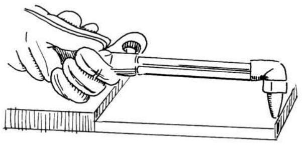
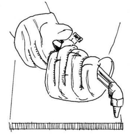
Put on your goggles and gloves and make several dry runs before lighting the torch. Make sure you are totally comfortable holding the torch in your right hand with your thumb on the cutting oxygen lever. Use your left hand for support and, if it is more comfortable, rest this left hand on a small block of wood or metal 8 to 10 inches from the line that is to be cut.
Using your left hand as a support and pivot, move the torch from one side of the cut to the other (from one side of the plate to the other). You will note that the cutting tip moves in a wide arc, so you must master the art of rolling your left hand and sliding the torch in such a way to keep the cutting tip on a straight line. This practice will be slightly uncomfortable, but will be quickly overcome by repetition as you use the cutting attachment.
Now that you have practiced supporting and guiding the torch on a straight line and have also consulted your tip charts for the correct tip size and pressures. you are ready to light your torch. Your first step before lighting the torch is to purge each of the hoses (both the acetylene and the oxygen) to make sure they are clear and the gases are separated. Make sure that the torch handle oxygen valve is wide open as you make your final preheat adjustment on the forward cutting attachment needle valve. Open the acetylene valve on the torch handle about one guarter of a turn and light the gas at the cutting tip with a spark lighter. Clear the smoke from the acetylene flame then slowly open the preheat oxygen valve until the flame becomes neutral (nice, clearly, defined preheat flames). Now press down on the cutting oxygen lever and make a final adjustment to the flames with the preheat oxygen valve. These adjustments will provide the correct preheat for the tip in use. If the flames burn away from the tip or less preheat is desired, close the acetylene torch valve until the flame in the cone shortens noticeably and readjust the flames to neutral with the preheat oxygen valve with the cutting lever depressed.


You are now ready to make your first actual cut. Your aloves and acades should be in place and your torch lit. Move the preheat flame to the extreme edge of the cutting line so that half of the flame is overhanging the side of the plate. This is done so that the preheat flames will heat the side of the plate as well as the top. The tips of the inner cone should be as close as possible to the metal without actual touching. Preheat the starting point until it turns bright red and just starts to melt. You should now depress the cutting oxygen lever slowly. During the preheating period, the tip should be perpendicular to the plate. At the moment the cutting oxvaen lever is gently depressed, the cutting tip should be tilted stightly in the direction of the cut. As the cutting commences, a shower of sparks will emerge beneath the plate. Now slowly move the torch in the direction of the cut. The correct cutting speed is accompanied by a sputtering sound and a steady stream of sparks. This results in a clean, slag-free cut with square top edge and bottoms. If movement is too fast, it does not allow enough time for the oxygen jet to go all the way through the metal, slag fills the kerf and the two pieces are not severed. Too slow a movement leaves a rounded top edge with slag sticking to the bottom of the metal. Like any of the other oxy-acetylene processes (welding, heating, brazing or cutting), it takes practice and some trial and error; but practice is the key word to becoming proficient.
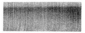
PERFECT CUT Shows regular surface with slightly sloping drag lines. Surface can be used for many purposes without machining.
EXTREMELY FAST Not enough time is allowed for slag to blow out of the kerf. Cut face is often slightly concave.

EXTREMELY SLOW
Produces pressure marks which indicate too much oxygen for cutting conditions.
TOO HOT PREHEAT
Rounded top edge caused by too much preheat. Excess preheat does not increase cutting speed. It only wastes gases.
GAS WELDING

PROPER FLAME SETTING
The function of a welding torch is to feed the proper volume of acetylene and oxygen to the mixer and welding tip.
At the prescribed pressure this correct volume is determined by lighting the acetylene as previously described (adjust until soot is barely visible) then bleed in oxygen until a neutral flame is adjusted.
If a smaller flame is required for the job, DO NOT reduce the acetylene flow at the needle valve or regulator. Replace the welding tip with a smaller size tip as reguired.
If a larger flame is required, replace the tip with a larger tip, readjust pressure according to the chart, and reset the flame as described previously.
Improper operation of a welding tip, i.e., wrong flow or wrong pressure, will cause problems doing the work properly and could result in backfire occurring at the torch.
The oxy-acetylene flame for welding is shown above, with the neutral flame being used for all gas welding operations. The neutral oxy-acetylene flame is desired

since it consumes all of the oxygen in the air around the welding area and leaves an uncontaminated weld area and a weld of maximum strength. An oxidizing flame is rarely used, and the carborizing flame is occasionally helpful when flame hardening for brazing. The welding torch is normally held similar to a hammer. Depending on whether you are right or left-handed, slant the tip about 45° in relation to the plate, with the flame pointed in the direction you want the weld to proceed. Since most people are right-handed, the weld would then start on the right hand edge of the plate and proceed leftward across the work, just the opposite of writing.
You should practice holding the tip around % inch above the metal and rotate it in a series of overlapping ovals, or if you prefer half moon movements, moving it from right to left as you practice. The diagram shows these patterns of movement. This should be practiced until you feel comfortable and your movement is smooth.
Running the bead is the next exercise, and a small welding tip should be used. Set the proper pressure according to the welding tip chart and use the recommended ¼ inch stock. Point the flame directly into the steel with the flame cone just above the metal surface. When a puddle is formed, move the torch back and forth and move the puddle across the steel. Do this slowly. It is necessary to have good penetration and this comes from a deep puddle. When moving the puddle, it is helpful to lean the tip about 45° away from the direction you want the puddle to move. Check your result with the photos below. Weld A is an example of a good weld, B shows overheating, and C shows insufficient heating. Again, practice here is the answer to becoming comfortable and proficient.
FUSION WELDING WITHOUT A ROD

PROPER WELD
OVERHEATING

INSUFFICIENT HEATING
Now that you have mastered fusion welding without a rod, you can move on to the next exercise which is running the welded bead with a welding rod. For this exercise, use sheet metal or plate % inch thick and a % inch steel welding rod. Place the rod in your left hand and the torch in your right. These should be positioned at 45° from the working surface but in opposed directions, so there is a 90° angle between the torch tip and the rod as shown in the illustration. You should then
synchronize the rod and torch movements. This is appreciably different from the exercise without rod. Your movements should duplicate the drawing below. These movements should be practiced without lighting a torch, until you feel comfortable doing them together.

Now it is time to light up and adjust to a neutral flame as in the fusion exercise. Apply the inner cone of the flame to a point about ¼ inch above the right side of the metal, keeping the end of the rod inside the outer envelope of the flame. As the puddle is formed, begin the synchronized movements of the torch and rod that you have been practicing. Keeping the molten puddle about ¼ inch in diameter, advance the torch and rod slowly in a straight line across the surface. Be sure to melt the rod in the puddle, not above it.
Observe the samples of the welds in the photos to determine if your technique is proper. At first, making a satisfactory weld will be difficult, but this technique can be developed rather rapidly with continuing practice.
FUSION WELDING WITH A ROD

INSUFFICIENT HEATING
BRAZING
Brazing differs from steel welding in that the two pieces of metal are not fused together. The brazing rod melts at a lower temperature than the parent metal and the brazed strength becomes the service overlay of the brazing rod. The advantage of brazing over steel welding is that it is the best way to join different or dissimilar metal. Almost any two metals can be joined except aluminum and magnesium. This is always done with either bronze or silver alloy rods.
Your flame setting for brazing is slightly "oxidizing". This is accomplished by first obtaining a neutral flame and then either increasing the oxygen or decreasing the acetylene slightly.
In the case of brazing, the flux is required to dissolve scale and oxides and to float them out of the braze. If flux is not used, the molten bronze will not adhere properly to the metal surface and you will have a weak joint. A bronze brazing rod is available with a coating of flux, thus the term "flux coated." This is more expensive than the conventional uncoated bronze rod which the operator heats and then dips in a can of brazing flux.
In brazing, as opposed to welding, you do not melt the edges of the material to be brazed, you simply heat them enough for them to melt the brazing rod. The flux then chemically cleans the work surfaces to make them free of oxide and other surface film. The melted rod will then cover the surfaces and fuse them together.
Bronze brazing differs from silver brazing only by the rod that is used. Bronze is less expensive than silver and should be used when the fit between the two metals to be joined is not closed. Again, the metals must be well cleaned, then the flame is played onto them until they become a dull red. Both pieces must be of equal temperature or the rod will float to the hotter piece. The rod is then touched to the preheated joint and melted. The rod then flows over the heated area bonding the metal together.
Silver brazing is a little faster than bronze brazing. This is because silver melts at a lower temperature and less heat is required. However, the joint must fit tightly together. Bronze bridges a gap much better than silver. Instead of putting flux on the silver rod the joint should be painted with flux. The way to determine when the metals are of a proper temperature is to watch the flux. When it bubbles, it is time to apply the silver. Silver melts when it is touched to the seam and freely flows over the fluxed area. Brazing is easy to master and is excellent for all joints which will be static (no outside motion) and not under extreme stress. However, seams which must stand shock, flexing or severe strain applied in a direction which tends to tear them apart should be welded.
SHUTTING DOWN WELDING EQUIPMENT
- 1. Close welding torch oxygen needle valve
- 2. Close welding torch acetylene needle valve.
- 3. Close both oxygen and acetylene cylinder valves.
- Open the welding torch acetylene needle valve and allow the acetylene pressure into regulator hose and torch to drop to zero. Close needle valve.
- Release the acetylene regulator adjusting screw by backing it out in a counter-clockwise direction until it rotates freely.
- Open the welding torch oxygen valve and allow the oxygen pressure in the regulator hose and torch to drop to zero. Close oxygen needle valve.
- Release the oxygen regulator adjusting screw by backing it out in a counter-clockwise direction until it rotates freely.
Your equipment is now in a shut down state, completely drained of gas.
SHUTTING DOWN CUTTING EQUIPMENT
- 1. Close preheat oxygen needle valve on cutting attachment.
- 2. Close welding torch acetylene needle valve.
- 3. Close both oxygen and acetylene cylinder valves.
- 4. Open the welding torch acetylene needle valve and allow the acetylene pressure in the regulator hose, welding torch handle and cutting attachment to drop to zero. Close the acetylene valve.
- Release the acetylene regulator adjusting screw by backing it out in a counter-clockwise direction until it rotates freely.
- 6. Open the preheat oxygen needle valve on the cutting attachment and allow the oxygen pressure in the regulator hose, welding torch handle and cutting attachment to drop to zero. Close preheat oxygen needle valve on cutting attachment and also close oxygen needle valve on welding torch handle.
- Release the oxygen regulator adjusting screw by backing it out in a counter-clockwise direction until it rotates freely.
GLOSSARY OF TERMS
| BACKFIRE |
The momentary recession of the flame
into the welding tip or cutting tip fol- lowed by immediate reappearance or complete extinction of the flame. |
|---|---|
| BASE METAL |
The metal to be welded, brazed, sol-
dered or cut. |
| FLUX | Material used to prevent, dissolve, or facilitate removal of oxides and other undesirable surface substances. |
| FUEL GASES |
Gases usually used with oxygen for
heating such as acetylene, natural gas, propane, methoacetylene, propa- dyne or other synthetic fuels and hy- drocarbons. |
| KERF | The width of the cut produced during the cutting process. |
|
NEUTRAL
FLAME |
An oxy-fuel gas flame in which the proportions used is neither oxidizing nor reducing. |
| POROSITY | Cavity-type deformities in the weld formed by gas pockets during hardening. |
|
PRE-HEAT
TEMPERATURE |
A specified temperature that the base
metal must reach before welding, brazing, soldering or cutting can be performed. |
|
REDUCING OR
CARBORIZING FLAME |
A gas flame having excessive fuel gas to oxygen mixture. |
| REGULATOR | A device for controlling the delivery of gas at a consistent pressure. |
| TACKWELD |
A weld made to hold parts of a weld-
ment in allignment until the final welds are made. |
| WELDMENT | An assembly whose component parts are joined by welding. |
| OXIDIZING | A gas flame having excessive oxygen |
A8


 Loading...