

CABINETMAKING, CARPENTRY AND CONSTRUCTION-WORK KNOW-HOW WITH CRAFTSMAN
"JOB-FITTED" BENCH SAWS
OVER 200 ILLUSTRATIONS

THIS BOOK COVERS SET-UPS AND OPERATIONS FOR ALL CRAFTSMAN BENCH SAWS. FOR CONVENIENCE, HOWEVER, ONLY THE 10-INCH BENCH SAW IS ILLUSTRATED HEREIN.
A MIDWEST TECHNICAL PUBLICATION
for
SEARS, ROEBUCK AND CO. – U. S. A. IN CANADA – SIMPSON-SEARS LIMITED
CAT. NO. 9-2929
PRINTED IN U.S.A.

CABINETMAKING, CARPENTRY AND CONSTRUCTION-WORK KNOW-HOW WITH CRAFTSMAN 'JOB-FITTED'' BENCH SAWS
OVER 200 ILLUSTRATIONS

THIS BOOK COVERS SET-UPS AND OPERATIONS FOR ALL CRAFTSMAN BENCH SAWS. FOR CONVENIENCE, HOWEVER, ONLY THE 10-INCH BENCH SAW IS ILLUSTRATED HEREIN.
A MIDWEST TECHNICAL PUBLICATION for
SEARS, ROEBUCK AND CO. – U. S. A. IN CANADA – SIMPSON-SEARS LIMITED
CAT. NO. 9-2929
PRINTED IN U.S.A.
SEARS
CRAFTSMAN BEN
JOB-FITTING A
STANDARD SAWI
DADO SAWING
PROBLEM SAWIN
SPECIALIZED SAV
MOLDING AND
WORK HELPERS F
BENCH-SAW KNOW-HOW
FIRST EDITION - 1967
COPYRIGHT 1967 - SEARS, ROEBUCK AND CO.
All rights in this book are reserved. It may not be used for dramatic, motion-, or talking picture purposes without written consent of the copyright holder. Nor may this book or any part thereof be reproduced in any manner whatsoever without permission in writing from the copyright holder, excepting cases in which brief quotations may be embodied in critical articles and reviews.
For information, address Legal Department 766, Sears, Roebuck and Co., Homan and Arthington Aves., Chicago, Illinois 60607.
A CRAFTSMAN HANDBOOK
CONTENTS
| E | |
|---|---|
| CRAFTSMAN BENCH SAWS AND ACCESSORIES | С |
| CHAPTER 1 | |
| JOB-FITTING A BENCH SAW TO YOUR REQUIREMENTS | 1 |
| CHAPTER 2 | |
| STANDARD SAWING OPERATIONS | 9 |
| CHAPTER 3 | |
| DADO SAWING OPERATIONS 2 | 0 |
| CHAPTER 4 | |
| PROBLEM SAWING OPERATIONS 2 | 5 |
| CHAPTER 5 | |
| SPECIALIZED SAWING OPERATIONS 3 | 3 |
| CHAPTER 6 | |
| Molding and sanding with your bench saw | 8 |
| CHAPTER 7 | |
| WOOD JOINTING - 32 WAYS 4 | 6 |
| CHAPTER 8 | |
| 3 |
o co.
be used without is book tsoever holder, nbodied
Sears, hicago,
INTRODUCTION

SEARS FINEST FOR HOMESHOP OR MEDIUM-DUTY PROFESSIONAL USE CRAFTSMAN 10-IN. BENCH SAW
• CUTS UP TO 3-3/8-IN. THICK • FREE-SLIDING MITER GAUGE
Truly a fine cabinetmaker's tool, but priced for the homeshop buyer. Convenient, large-handled controls make it easy to raise and lower or to tilt the blade to precise settings. Rip fence locks front and rear in accurate alignment with the blade . can be vernier set and locked, or be removed at any position. Accurate-setting miter gauge slides freely in table groove at either side of blade. Furnished with 10-in. Kromedge blade for fast, smooth cutting. Motor is not included.
• POSITIVE-LOCKING FENCE SPECIFICATIONS Blade Size – 10" with 5/8" hole Blade Speed – 9,000 ft./min. Blade Tilt – 45° left Table Size – 20" wide x 27" long Ence L ength – 34"
Fable Size – 20" Wide X 2/" long Fence Length – 34" Dado Capacity (7" Size) – 13/16" wide x 1¾" deep Overall Size – 15"Hx23¾"Wx28"L
- EXTRAS -1. Guard and Splitter
• EASY-TO-USE TILTING ARBOR
- 2. Miter-Gauge Hold-Down
- 3. Adjustable Table Extension .
- increases width up to 20 inches 4. Grid-Type Table Extension .
- adds 10 inches to width
- 5. Miter-Gauge Stop Rod
- 6. Bench or Pedestal (page A-3)
– ALSO AN 8-INCH MODEL –
Similar in design to the 10-in. model — with the same extras available — this model provides a cutting depth of up to 2½ in. and a table area of 17x20 in.


A compact, portable craft shops. Has self-aligning fence t setting miter gauge in. Kromedge Blade, with Overload Prote shown.
CRAFTSMA HEAVY-
12-IN. FLOOR S
- INTEGRAL, DIRECT-MOTOR — Develop
- INTEGRAL, STURDY
- BUILT-IN ON-OFF S • EXTRA LARGE TAB width when extend
- MICRO-ADJ. RIP FE
- EXTREMELY ACCUR QUICK-ACTING CO
- BUILT-IN SAWDUS (For Use With Hom
Built for the profess in. cut to center of Micro-adj. fence el sion. Electro-Mag Guard with Splitter and stop rod availab
)P L USE
TING ARBOR
CATIONS with 5/8" hole 000 ft./min. left wide x 27" long 34" "Size) – 13/16" tep "Hx23¾"Wx28"L RAS – litter old-Down ble Extension ... th up to 20 inches ole Extension ... s to width top Rod estal (page A-3)
e – this 7x20 in.

INTRODUCTION
CRAFTSMAN 7%-IN. BENCH SAW
- INTEGRAL MOTOR -Develops 1 H.P.
- LARGE 14x26-IN. TABLE (inc, 2 furnished extensions)
- CUTS TO 1-5/8 IN. THICK
- · CONVENIENT SWITCH
- ALUMINUM GUARD
- DUAL MITER-GAUGE SLOTS
A compact, portable, precision-built tool especially designed for home and craft shops. Has separate controls for blade elevation and blade tilt . a self-aligning fence that lifts off at any point . and a free-sliding, accurate-setting miter gauge for 45° right- or left-angle miters. Furnished with 7-1/2-in. Kromedge Blade, Swing-Away Guard and Splitter, Built-In Capacitor Motor with Overload Protector, convenient Off-On Switch and Table Extensions as shown.
CRAFTSMAN HEAVY-
DIITY
12-IN. FLOOR SAW
- INTEGRAL, DIRECT-DRIVE MOTOR - Developes 3 H.P.
- INTEGRAL, STURDY NON-TIP STAND
- BUILT-IN ON-OFF SWITCH
- EXTRA LARGE TABLE up to 57 in. width when extended as shown
- MICRO-ADJ. RIP FENCE
- EXTREMELY ACCURATE, QUICK-ACTING CONTROLS
- BUILT-IN SAWDUST COLLECTOR (For Use With Home-N-Shop Vac p. A-4)
- (For Use With Home-N-Shop Vac p. A-4)
Built for the professional . priced for the homeowner. Allows up to a 3-9/16in. cut to center of 76-in. workpiece, with 13-1/2 in. of table in front of blade. Micro-adj. fence eliminates trial runs; also an extra fence on adj. table extension. Electro-Magnetic Brake; Overload Protector; 12-In. Kromedge Blade; Guard with Splitter; 8-Ft. Cord — for 110 or 220 V. (Miter-gauge hold-down and stop rod available extra.)
INTRODUCTION

CRAFTSMAN KROMEDGE SAW BLADES
Whatever your cutting requirements, there is a quality Croftsman blade especially designed for the job. Craftsman blades stay clean (gum and rust resistant) and sharp longer, and cut smoother than ordinary steel blades. Each is made of finest saw steel and is Kromedge treated to increase the hardness and wearability of the surface and cutting edges. Blades listed below are available for 71/2, 10 and 12-in. Sears Bench Saws.
- 1. FREE SMOOTH-CUT COMB.
- 2. FREE-CUT RIP
- FREE-CUT COMBINATION
- CABINET COMBINATION
- 5. OLD-WOOD, NAIL CUTTING
- 6. CHISEL-TOOTH COMBINATION THIN-RIM VENEER
- 8. THIN-RIM CABINET COMB.
- 10. CARBIDE-TIPPED
- 11. STEEL SLICER
- 12. MASONITE CUTTING
- 13. NON-FERROUS METAL
DADO HEAD SETS
No. 1 is best, professional-quality, satin-cut, 7" set - will even cut veneers and plywoods with practically no splintering. Dadoes to 1-1/4" deep. No. 2 is 8" heavyduty set for extra tough jobs. Dadoes, to 1-3/4" deep. Both are Kromedge quality.

2 1/8" outside cutters, 4 1/8" chippers and 1 1/16" chipper. Assembles to 13/16" width.

2 1/8" outside cutters, and 6 1/8" chippers Assembles to 1" width.

Tungsten-carbide is one of man's That's why this hardest metals. carbide-tipped, Kromedge blade cuts so fast - stays sharp so long. Blade cuts smoother, feeds more evenly and takes less power than regular blades. Cuts all woods, most plastics, wallboard, thin brass or aluminum. Outlasts an ordinary blade 20 to 1.
MOLDING HEADS AND CUTTERS


1-Cutter Head, with 5-5/8" cutting dia., is excellent for 71/2 and 10-in. bench saws. Set includes 18 different shape bits to mold various trim, edging and joint designs, with unlimited variations if bits are used in combinations.
3-Cutter Head, available in 4-3/4-in. and 7in. cutting dia. - either in sets with an assortment of most popular bits, or heads only and 18 separate cutter patterns.
ADJUSTAB

width from 1/4" to 13/16" from the saw. Calibration depth of cut is 2". Tool precision-ground, carbide-tig any type of required dado cu and fast. Excellent for p Sears bench saw.

Clamps to auxiliary fench steel fingers to hold work against the fence.
BENCH-HEIGH
A rigid, substantial venient operation no provides maximum must frequently be

Rigid angleavailable in
nished unassembled. Speciper set) can be added for ease
SAW BLADES

an-carbide is one of man's metals. That's why this -tipped, Kromedge blade cuts - stays sharp so long. Blade noother, feeds more evenly and ess power than regular blades. I woods, most plastics, wallthin brass or aluminum. Outl ordinary blade 20 to 1.
DING HEADS


with 5-5/8" cutting dia., is 2 and 10-in. bench saws. Set different shape bits to mold dging and joint designs, with ations if bits are used in
available in 4-3/4-in. and 7-. — either in sets with an asost popular bits, or heads only e cutter patterns.

Precision cut, adjustable hub permits dialing any width from 1/4" to 13/16" without removing blade from the saw. Calibrations are in 1/16". Max. depth of cut is 2". Tool steel, 7" blade has 8 precision-ground, carbide-tipped teeth – will make any type of required dado cut, smoothly, accurately and fast. Excellent for plywoods. Use on any Sears bench saw.
HOLD-DOWN ATTACHMENT

Clamps to auxiliary fench. Provides 4 adjustable steel fingers to hold work safely down and in against the fence.


Mounted at each side of a saw blade these 4" dia. stabilizers impart the extreme rigidity required to completely abolish blade tremor and produce the ultimate in smooth, true cutting as required for top-quality cabinetwork joints. For use with any flat-ground blade of 7" or greater size.

A very accurate, easy-to-use, all-aluminum jig for easy plotting and sawing of single or double tapers. Also useful for molding or dado cuts on tapered pieces.
BENCH-HEIGHT MOUNTS FOR 8- AND 10-IN. BENCH SAWS
A rigid, substantial mount to place your saw table at proper height for convenient operation not only adds to the ease and pleasure of your work, but also provides maximum safety. A movable mount is desirable where saw position must frequently be shifted to accommodate various sizes and shapes of work.

INTRODUCTION
SANDING WHEELS FOR BENCH SAWS
Mounted in place of blade, a sanding wheel converts your Bench Saw into a firstrate disc sander – for edge (square or bevel) or limited surface sanding. Karbo-Grit Wheels (at left) are long-lasting metal discs with abrasive grains permanently wheels (at ref) are inigrating metal offices with advance grains permanently bonded on — coarse grit on edge and one side, med. grit on second side. The wheel at right is a heavy steel disc to which replaceable sandpapers in grits as desired can be cemented. These wheels are furnished with coarse and med. grits desired can be cemented. on them, and replacement sandpaper discs come in pkgs. of 6 containing 2 each: coarse, med. and fine grits.


Hardened, ground 50-MM lenses; adjustable plastic frames; side shields.

plastic lens in a plastic frame to fit over spectacles.

CRAFTSMAN HOME-N-SHOP VAC
FOR USE WITH 12-IN. BENCH SAW
This Home-N-Shop Vac is a special shop vacuum that collects sawdust as it is made, before it falls to the floor. Can be directly attached to the fully-enclosed body of the 12-in. model saw . or can be used with other model saws if bench space below saw body is fully enclosed and fitted to receive vac-hose end. Also excellent for cleaning litter from shop floor, workbench top, etc.
band.

SELECTING A BEN
The principal consider lecting a bench saw i cut needed for the typ done. On a construct possibly, for production it generally is nece through 2-in. lumber casionally, through 4 On the other hand, seldom requires sawin thing larger than a 2x of the wood used do 1-in. thickness.
A bench saw is rate the maximum diamete take. Remember, how arbor occupies a porti (the max. cut of an only 2-1/2 in.). Re: that tilting the blade ting will further redu thickness through whi


A-4

al shop vacuum that colore it falls to the floor. Illy-enclosed body of the e used with other model ody is fully enclosed and so excellent for cleaning op. etc.
CHAPTER 1 JOB-FITTING A BENCH SAW
TO YOUR REQUIREMENTS
SELECTING A BENCH SAW
The principal consideration when selecting a bench saw is the depth of cut needed for the type of work to be done. On a construction job — and, possibly, for production-line work it generally is necessary to saw through 2-in. lumber . and, occasionally, through 4x4-in. pieces. On the other hand, homeshop use seldom requires sawing through anything larger than a 2x4, and the bulk of the wood used does not exceed 1-in. thickness.
A bench saw is rated according to the maximum diameter blade it will take. Remember, however, that the arbor occupies a portion of the blade (the max. cut of an 8-in. blade is only 2-1/2 in.). Remember, also, that tilting the blade for bevel cutting will further reduce the vertical thickness through which it can cut.
Furthermore, a blade cuts faster and easier when a greater amount of the blade is projecting above the top of the work being cut. Therefore, even though a bench saw is capable of square-cutting through a certain maximum thickness workpiece, it will not (in one pass) cut a 45o bevel through this same thickness workpiece . nor will it continuously sever workpieces of this maximum thickness with the speed and ease to be expected from a larger size bench saw.
If you will do hobby work, taking two passes for a cut through and/or sawing occasional large pieces more slowly may not greatly inconvenience you . but if the bench saw will contribute toward your income, it is far better to purchase the largest size saw you are likely to need. Each larger size Craftsman saw also offers other advantages: A larger worktable: easier handling blade ele-


SQUARE-CUT DEPTHS
45° BEVEL-ANGLE CUT DEPTHS
MAXIMUM CUTTING DEPTHS FOR 8-, 10- AND 12-IN. SAWS
vation and tilt controls; a more accurately aligning and positive locking fence; superior ruggedness and stability - and, in the case of the 12-in. saw, an integral motor and stand and built-in provision for sawdust collection. All Craftsman bench saws are designed and built for accurate, dependable sawing.
POWERING A BENCH SAW
Motor Selection
The 7-1/2- and 12-in. Craftsman saws have built-in, direct-drive motors that develop all the power needed for the work intended. Motors are not furnished with the 8-in. and 10-in. saws. The 8-in. saw should have at least a 3/4 hp motor; the 10-in. at least a 1 hp motor. In each case use a 3450 rpm capacitor-start motor. preferably with a built-in overload protector. Also, use the size motor pulley recommended in the instruction sheet furnished with your tool. Never underpower your saw if you expect it to do excellent work.
Proper Wiring
Make certain that your power supply is the same rated voltage and current (AC or DC) specified on your tool motor nameplate ... and, if AC, that the phase and cycle are the same. Moreover, if there is any doubt, check (or have the power company check) to make certain that the voltage being
delivered to your motor does not drop more than 10% below the rated amount. An excessive voltage drop can occur, for instance, in an old building not originally wired for all the electricity being consumed by the many modern electrical appliances now in use ... or in a farm barn to which the wiring is undersized or poorly insulated. Any drop in voltage has the same effect on your tool motor as overloading it . can, if consistently extreme. damage the motor and will, in any event, make it run less efficiently.
For the above reason, also make certain that any extension cord you use for connecting the motor to the power supply is of sufficient size.
RECOMMENDED WIRE SIZES
| LENGTH | WIRE | SIZE |
|---|---|---|
| OF RUN | For 115V | For 230V |
| Up to 100 ft. | No. 10 | No. 12 |
| 100 to 150 ft. | No. 8 | No. 10 |
| 150 to 200 ft. | No. 6 | No. 8 |
| 200 to 400 ft. | No. 4 | No. 6 |
Even a thermal overload protector does not protect a motor from line voltage surges due to short circuits or other causes. For maximum protection, fuse the circuit to your motor with a time-lag fuse rated the same as the running amps specified on the motor nameplate. Also, for your own safety, properly ground the adapter plug furnished with your motor.
PROPER GROUNDING ADAPTOR
GROUNDIN
MOUNTING A BE
For sawing ease an cutting, the saw mu it will remain sta table top reasonab height convenient t at your waistline above). Work can straight on a tilted a saw that "walks" duction-type workth in a substantial ben is flush with the s extended at each provide ample worl space is limited, ho steel bench or ped A3) (or, for the 12 integral stand), will versatile arrangeme ing permits the s about as required different shapes of or to be stored aga not in use.
Ample light is essen tool operation prope

SO BEVEL-ANGLE CUT DEPTHS
IN SAWS
motor does not drop low the rated amount. age drop can occur an old building not for all the electricity by the many modern nces now in use ... to which the wiring r poorly insulated. ore has the same efmotor as overloading onsistently extreme or and will, in any run less efficiently.
reason, also make extension cord you ng the motor to the of sufficient size.
DED WIRE SIZES
|
WIRE
or 115V |
SIZE |
|---|---|
| No. 10 | No. 12 |
| No. 8 | No. 10 |
| No. 6 | No. 8 |
| No. 4 | No. 6 |
overload protector t a motor from line lue to short circuits For maximum procircuit to your motor fuse rated the same mps specified on the . Also, for your own ground the adapter ith your motor.

MOUNTING A BENCH SAW
For sawing ease and for accuracy in cutting, the saw must be mounted so it will remain stationary, with the table top reasonably level and at a height convenient to you (generally, at your waistline or a few inches above). Work cannot be fed truly straight on a tilted table top, nor to a saw that "walks" about. For production-type work the best mounting is in a substantial bench the top of which is flush with the saw table top and extended at each side and back to provide ample work area. Wherever space is limited, however, either the steel bench or pedestal stand (page A3) (or, for the 12-in, saw, its own integral stand), will provide a more versatile arrangement. Such a mounting permits the saw to be moved about as required to accommodate different shapes of workpieces . or to be stored against a wall when not in use.
Ample light is essential for doing any tool operation properly — and safely.
Light source preferably should be directly above the table top to avoid casting shadows. It isn't feasible to mount a worklight directly on a bench saw table edge . but provision should be made, wherever necessary, for a worklight (bage A4) or an overhead fixture that can be directed down at the table ton
ADJUSTING A BENCH SAW
Accuracy Is Important
Accurate adjustments are necessary not only to produce good work, but also for safety. A saw that is not trued cannot be expected to make straight, clean cuts . moreover. if fence and blade are not parallel the work can become wedged between them and be kicked back with considerable force. On the other hand. even an inexpensive tool can be made to produce excellent work, if properly adjusted. Checkyour saw adjustments frequently.

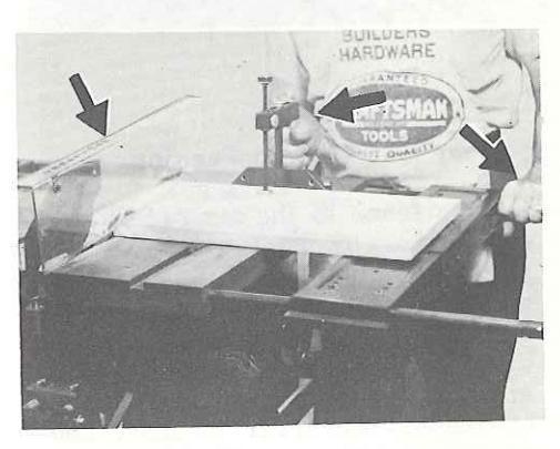
1. Paralleling Blade With Grooves
Set the blade at its highest. Mark the tooth that is just above the table at the front edge of the blade. Measure the distance from the outer edge of this tooth to the nearest edge of the right-hand table groove. Now rotate the blade slowly by hand to place this same tooth just above the table top at the rear edge of the blade. Again measure the distance between this tooth and the same groove. The two measurements should be identical.
If necessary shift the table or trunnions on the base until the measurements are equal. This usually can be done by loosening the bolts that secure the table or trunnions to the base, there being enough play at the bolt holes to permit adjustment when the table edge is tapped lightly with a wooden mallet.
2. Paralleling Fence With Blade
Refer to the instructions packaged with your bench saw. In general, the fence — at any setting — must be parallel to the table grooves. You can check this by measuring the dis-
tances (which must be equal) between each end of the fence and one of the grooves . and by hand setting the fence, as you lock it at a position, if necessary. However, a good fence should be self-aligning if in proper adjustment as explained in the instructions for your model saw.
3. Adjusting Tilt Scale
Using an accurate square, set the blade at an exact right angle to the table top. Now adjust the pointer on the tilt scale to read "O". Also, if there is a stop nut (or nuts) to restrict movement below "O" (or above "45"), make these adjustments also.
4. Adjusting Miter-Gauge Scale
Engage the locating pin in its 00 detent, then adjust (and tighten) the pointer at the 0 mark on the scale. If there is no locating pin, use an accurate square to set and lock the gauge head at 900 to the gauge blade. In each case, make a trial cut, check the cut with a square . and readjust as necessary.

5. Adjusting the F
If there is a scale the fence exactly as measured with tighten the fence p scale. Do this at a
6. Adjusting the St
The splitter serve (saw cut in workpic the cut from spring the blade sides, an complish this the perfectly aligned Shims are furnishe this purpose. Refer packaged with your
SAW MAINTENA
Keep your saw as and lubricated in ac instructions furnis particular, keep th the blade elevating clean and dry to pro of sawdust that will erations. Keep tab guide bar and miter a rust inhibitor Above all, keep the and sharp.
SELECTING THE SAW BLADE
Your Craftsman E fitted with a Cra Blade selected for is an excellent all-----------------------------------
All toothed blades
FOR B
st be equal) between fence and one of the d by hand setting the ck it at a position, if wever, a good fence ligning if in proper xplained in the inur model saw.
Scale
ate square, set the at right angle to the adjust the pointer on read "O". Also, if nut (or nuts) to rebelow "O" (or above e adjustments also.
er-Gauge Scale
ting pin in its 00 dest (and tighten) the mark on the scale. locating pin, use an to set and lock the 0 to the gauge blade. ke a trial cut, check square . and reary.

5. Adjusting the Fence Scale
If there is a scale, position and lock the fence exactly 1 in. from blade as measured with a ruler. Set and tighten the fence pointer at 1 on the scale. Do this at each side of blade.
6. Adjusting the Splitter
The splitter serves to keep the kerf (saw cut in workpiece) open to prevent the cut from springing closed against the blade sides, and binding. To accomplish this the splitter must be perfectly aligned with the blade. Shims are furnished with the tool for this purpose. Refer to the instructions packaged with your saw for their use.
SAW MAINTENANCE
Keep your saw as clean as possible, and lubricated in accordance with the instructions furnished with it. In particular, keep the Acme threads of the blade elevating and tilting screws clean and dry to prevent accumulation of sawdust that will hamper their operations. Keep table top, fence, fence guide bar and miter gauge coated with a rust inhibitor or preservative. Above all, keep the blade rust free and sharp.
SELECTING THE PROPER SAW BLADE
Your Craftsman Bench Saw comes fitted with a Craftsman Kromedge Blade selected for general use. This is an excellent all-purpose blade, but will not do special cutting with the ease, precision and smoothness to be obtained by using a blade especially designed for the purpose. It will greatly improve the quality of any specialized cutting you do — such as tenoning, plywood or hardboard sawing. etc. — to use the proper blade.
All toothed blades belong in one of

three classes, depending upon how the blade is designed to provide its own clearance so as not to bind in the kerf.
SWAGED-TOOTH CLASS. The teeth of this type blade are wider than the rest of the blade. There may be only 8 or as many as 40 teeth. Carbidetipped blades belong in this class ... the (wider) carbide tips are brazed onto the outer edges of the teeth.
HOLLOW-GROUND CLASS. This type of blade is relatively thick at the edge and progressively thinner toward the hub due to tapering of the sides. Full hollow-ground blades are thus tapered from rim to center, and the teeth do not require setting. There is, however, a new class of "Free-Cut" blades which have a thick, wobblefree, flat-ground center hub surrounded by a taper-ground, "working-area" rim — and the teeth of this type may be slightly set. All smooth- and thincutting blades are fully or partially tapered, some without and some with set teeth.
SET-TOOTH CLASS. A blade of this type is uniform in thickness throughout, but the teeth are set (bent) outward at the edge according to a predetermined pattern so that the cutting edge is effectually wider. The general-purpose chisel-tooth and faster, rougher-cutting blades are mostly of this type.
FOR BEST PERFORMANCE ALWAYS KEEP YOUR SAW IN ADJUSTMENT - AND YOUR SAW BLADES SHARP
Fast-Cutting Shop and Contractors' Blades

CHISEL-TOOTH COMBINATION. All-purpose, sturdy blade for ripping, crosscutting or mitering of any wood. Is an excellent contractor's framing blade. Set-tooth.


CABINET COMBINATION. For general cabinetwork. Rips, crosscuts or miters in hard or soft woods. An excellent contractor's trim and finish blade. Settooth.
PLYTOOTH BLADE. For general purpose sawing of plywood in any direction without splintering - or crosscutting and mitering on hard or soft wood. Excellent for sawing Celotex and other wood-fiber materials. Set-tooth.

MASONITE SIDING BLADE. Designed especially for fast, continuous sawing of Masonite siding, decorative hardboards and waterproof plywoods. Set-tooth.

NAIL-CUTTING BLADE. The only blade for sawing through salvaged lumber or rough timber that may contain an occasional nail or wire. Made of extrahard alloy steel to withstand such usage. Will rip, crosscut or miter cut. Set-tooth.
Heavy-Duty, Production-Type Blades

SAFE-SAW CARBIDE-TIPPED BLADE. Has 8 or 12 teeth (depending upon size). Rips, crosscuts or miters with exceptional smoothness and freedom through any wood - even the hardest. Willoutlast other types many times. Is not, however, intended for nail cutting. Swaged-tooth.

MASONITE CARBIDE-TIPPED BLADE. An industrialquality, alternate top-bevel ground blade designed for continuous sawing through Masonite and similar abrasive materials. Excellent for crosscutting or mitering of all woods, plywoods, veneers, Celotex, plastics, Formica and plastic laminates. Swaged-tooth.
A SHARP BLADE IS THE SAFEST
6


Professional, Cab
FREECUTTING R
for clean, fast saw
Extra deep gullets
eliminate binding. tion and wobble. A
and set for cross
soft or hard woo minimizes vibratio and more accurate
SMOOTH FREEC
Sears finest comb joint cuts, leaving
cuts or miter cut and wobble; expa
true, quiet operati
THIN-RIM SATIN best blade for pr and similar mate
mitering and cutti
rim produces an e
TENONING BLAI average blade that with precision crosscuts or mit Taper-ground.
Dado Heads and
(See pages A2 and 1 The conventional is for heavy-duty the adjustable da extra long serv type dadoing. Bot
All-nurnose sturdy or mitering of any r's framing blade.
meral cabinetwork. ard or soft woods. finish blade. Set-
t splintering - or or soft wood. Exper wood-fiber ma-
gned especially for e siding decorative ds. Set-tooth.
gh timber that may e. Made of extra-
crosscuts or miters freedom through outlast other types tended for nail cut-
ADE. An industrialblade designed for e and similar abrasscutting or miters, Celotex, plastics, vaged-tooth.
l purpose sawing of
ly blade for sawing h usage. Will rip,
LADE. Has 8 or 12
Professional Cabinetmakers' Blades
FREECUTTING RIP BLADE. Taper ground and set for clean, fast sawing of all solid woods with the grain. Extra deep gullets sweep out all sawdust to practically eliminate binding. Extra heavy hub minimizes vibration and wobble. Also excellent for resawing
FREECUTTING COMBINATION BLADE, Taper ground and set for crosscutting, ripping or miter cutting of soft or hard woods - without hinding Heavy hub minimizes vibrations and wobble. Cuts cleaner faster and more accurately than ordinary flat-ground blades.
SMOOTH FREECUTTING COMBINATION BLADE. Sears finest combination blade. Makes precision gluejoint cuts, leaving a smooth, square cut, Rips, crosscuts or miter cuts. Heavy hub minimizes vibration and wobble: expansion holes and slots ensure free true, quiet operation. Taper ground and set.
THIN-RIM SATIN-CUT VENEER BLADE. Sears best blade for precision cutting of plywood, veneers and similar materials. without splintering. Also for mitering and cutting of laminates and plastics. Thinned rim produces an extra fine cut. Taper-ground.
THIN-RIM SATIN-CUT COMBINATION BLADE. Sears best all-purpose cabinetmaker's blade for use on solid woods - all fine trim and finish work, Rips. crosscuts or miters. Extra heavy body provides stability: thinned rim produces an extra fine, smooth cut. Taper-ground.
TENONING BLADE (8-IN. ONLY). A thicker than average blade that cuts square-bottom 1/8-in, grooves with precision - to assure hairline joints. Rips. crosscuts or miter cuts through any type of wood. Taper-ground.
Dado Heads and Adjustable Dado -
(See pages A2 and A3 for illustrations.) The conventional flat-ground dado is for heavy-duty dadoing . and the adjustable dado blade will give extra long service for production type dadoing. Both produce clean-cut
grooves in solid woods. However, for clean, smooth, splinter-free dadoing of plywood, veneer, laminate, mosaic and furniture wood we strongly recommend use of the thin-rim, satincut dado made especially for such work.


Metal-Cutting Blades

STEEL SLICER. A special design blade that quickly slices through sheet iron or steel by "burning" a kerf. Sparks are produced and Safety Glasses (page A4) should be worn. Not recommended for sawing aluminum, brass or other non-ferrous metals; but will saw cleanly through Plexiglas, Lucite and similar plastics if work is fed steadily (without stopping) so that no one spot becomes over-heated.
NON-FERROUS METAL BLADE. Designed for sawing aluminum, brass, bronze, copper, zinc and other non-ferrous metals. A professional-quality, extra durable blade. Safety Glasses (page A4) should be worn . and best results will be obtained by using a lubricant (such as a tallow candle) on blade teeth, and a moderate rate of feed.
USE OF SAW-BLADE STABILIZERS
Tapered steel Blade Stabilizers (page A3) clamp blade rigidly to reduce
blade wobble. Produce truer, smoother cuts and result in longer blade life. Recommended for all flat-ground blades, but not for hollow-ground or thickened-hub (thin-rim) blades.
KEEP YOUR BLADE RUST FREE AND SHARP FOR SMOOTH, ACCURATE CUTTING
For sharpening and/or reconditioning see any Sears Retail or Mail Order Store . or refer to Sears Do-It-Yourself Booklet, "How to Sharpen", Cat. No. 9-2924.

Floppy sleeves, loose-end of appa tion to danger as to being caught by (or even by an ung to pull you into con should either be fa or be tightly rolle ones); you should ... or loose shirt apron, tied in b Also - and very glasses or some face shield (page eyes from sawdust - particularly if v tle plastic or meta
Never Stop Bein
One moment of i you a painful inj operations are so done that some op come careless a not fall into this
n blade that quickly by "burning" a kerf. Glasses (page A4) ed for sawing alubus metals; but will aucite and similar vithout stopping) so ted.
Designed for sawper, zinc and other mal-quality, extra age A4 ) should be e obtained by using dle) on blade teeth,
duce truer, smoothin longer blade life. or all flat-ground or hollow-ground or n-rim) blades.
P rs Retail Yourself
CHAPTER 2 STANDARD SAWING OPERATIONS


--------------------------------------
Dress Properly
Floppy sleeves, a necktie or any loose-end of apparel are an invitation to danger as these are subject to being caught by the whirling blade (or even by an unguarded motor shaft) to pull you into contact with the blade (or wrap you around the shaft). Sleeves should either be fastened at the cuffs. or be tightly rolled up (or be short ones); you should not wear a necktie . or loose shirt tails. etc. A work apron, tied in back, is excellent. Also - and very important - wear glasses or some type of goggles or face shield (page A4) to protect your eves from sawdust or flying splinters - particularly if working with a brittle plastic or metal.
Never Stop Being Careful
One moment of inattention can cost you a painful injury. Most sawing operations are so quickly and easily done that some operators tend to become careless and inattentive. Do not fall into this unsafe habit .
and don't permit anyone else to distract you. Always be alert!
A Low Blade Is Safest

When the blade is elevated just enough to clear the top of the workpiece there is, obviously, less exposed blade to cause possible injury than when a large amount of blade projects above the workpiece. Also, in most cases, there will be less of the blade inside of the kerf — and, therefore, less likelihood of kickback should you accidentally twist the workpiece.
These factors make it generally more desirable to operate with a "low" blade, even though a low blade — due to the longer angle of blade inside the workpiece — consumes a little more power and requires a little more feed pressure than a high blade. A properly powered saw will produce just as excellent work with the blade low.
Avoid Kickbacks
Anything that will cause the blade to bind in the work will cause a kickback (a thrusting of the workpiece backwards, toward the operator). Most common causes of kickbacks are: 1) Twisting the workpiece out of line when freehand feeding. 2) Misalignment of fence and blade so that work becomes wedged between them when feeding. 3) Failure to use the splitter (or to otherwise hold the kerf open) so that a long kerf closes around the saw blade. 4) Feeding too rapidly especially if wood is resinous, damp or knotty. 5) A dull or rusty blade. 6) Holding the work too loosely or carelessly.
Under certain circumstances kickback can occur with sufficient violence to cause injury. On the other hand, if you will use the splitter (or wedge the kerf open when necessary), use a clean, sharp blade, and feed the work carefully, there is little chance for a severe kickback to occur. And if you hold the workpiece firmly down on the table at all times, any slight kickback tendency that might develop will cause no problem. Use of a Hold-Down (page A4) is recommended for all workpieces too large or small for your hands to hold firmly down.
Warped or crooked workpieces also can cause kickback, especially if placed on the table or against the fence in a manner that permits rocking or twisting while feeding. Always make certain that the work will slide on the table or along the fence without tendency to bind the saw blade.

Keep Hands Clea
Never put your h allowing them to g or in line with the work. One mista to allow a thumb over in front of th ing, with the inter hand into a safe the cut is nearly tracted you could hand to safety so your hand could the blade. Anoth is to squeeze the and blade to push workpiece. If w hand should slip trouble.
Best practice is hand in such a pos chance, it should suddenly forward by one side of t toward the blade blade and fence least as much a flattened hand), a hand to push wor ... then hook t over the fence steady, and tuck in under your pal the workpiece en space is too narr push stick (page to back of saw through.
In General
Ripping is the saw with the grain. with the fence as and maintain the width for the cut. can be ripped s with a sharp blade impossible to hol cut without using reason the work
10

Keen Hands Clear of the Blade
Never put your hands in jeopardy by allowing them to get close to the blade or in line with the blade when feeding work One mistake easy to make is to allow a thumb or finger to hang over in front of the blade while feeding with the intention of sliding your hand into a safe position later when the cut is nearly finished. If distracted you could forget to slide your hand to safety soon enough . or your hand could slip and carry on to the blade. Another common mistake is to squeeze the hand between fence and blade to push through a narrow workpiece. If work should bind or hand should slip you might be in trouble
Best practice is to always keep each hand in such a position that if, by any chance, it should be pushed or carried suddenly forward it will pass safely by one side of the blade instead of toward the blade. If space between blade and fence is amply wide (at least as much as the width of vour flattened hand), and you do use your hand to push work through this space then hook the two outer fingers over the fence to hold your hand steady, and tuck your thumb safely in under your palm to hook it against the workpiece end (for pushing). If space is too narrow for safety. use a push stick (page 13) - or walk around to back of saw and pull the work through.
In General
Ripping is the sawing through of wood with the grain. It generally is done with the fence as a guide to position and maintain the work at the correct width for the cut. In fact, most woods can be ripped so freely and easily with a sharp blade that it is practically impossible to hold to a true, straight cut without using the fence. For this reason the work must be held firmly

Two Obvious Don'ts
Don't reach up to the saw blade to grab a piece of free wood — until the blade has stopped. Don't let the floor become littered so that your footing is uncertain. Also, sawdust is a definate fire hazard, especially after having been damp, and should never be allowed to accumulate.
--------------------------------------
against the fence (as well as firmly down on the table) while feeding it. Hence, the workpiece edge against the fence must be straight, if cut is to be straight.
NOTE
If there is no straight edge to slide along the fence refer to page 10 , or to page 29 for use of cut-off board.

Proper Set-Up and Feeding
Set the fence to the desired width of cut, either by using a mark on the workpiece, the fence guide-bar scale, or a ruler. Plan so that the kerf will be in the scrap side, which can be the portion of workpiece between the blade and fence or the portion at other side of blade, whichever is most convenient. Make certain (if there is any cause for doubt) that fence is aligned parallel to the blade, then lock it in position. Turn motor on.

Use of the saw guard is recommended; the splitter should always be used when making any rip cut longer than three times the saw blade diameter especially if wood is green or damp. Should the splitter not be used, then work should be stopped, after ripping a 12- to 18-in. kerf, and a wedge should be inserted to hold the kerf open, before finishing the cut. The longer the cut you make without having the splitter or a wedge to hold the kerf open, the more likely will be the chance of binding the blade to cause kickback and spoil the cut.
If the fence scale or a ruler is used the setting will be distance A – and the distance B will be workpiece width minus A plus thickness of the blade.

SETTING THE FENCE
Place work flat on table, holding it down and against the fence, and feed it to the blade about as fast as the blade can take it without noticeable overloading of the motor. Try to keepfeeding at a uniform rate throughout, changing the pace only if knots, etc. make this necessary. A uniform feed produces a smoother cut. Stopping at any point may leave a saw mark or discoloration on the cut edge. However, if for any reason you have to walk around to the back of the saw (to insert a wedge or to finish by pulling through), back the work up an inch or two and continue to hold it firmly down and against the fence while walking around. Preferably, do not stop the blade; but if you should, be certain it is again running at full speed before resuming the operation.
Never reach o part of the w through it. Ho most practical, side of the sa and grasp the front edges to h the fence while tion to feed it t
If necessary, ripping operati to the rear of t work through. keep your hand while walking not in use be squeeze the ke the work thro avoid pulling sible . it i work against straight cut.
Handling Narr
It is difficult against the fem – and often the feed it all the For holding we the fence the down (page A4 best is the us down and hold a wood block held in one h work during the (when end is push stick.
12
ruard is recommended: ould always be used ny rip cut longer than saw blade diameter ood is green or damp. tter not be used, then stopped, after ripping n. kerf. and a wedge rted to hold the kerf nishing the cut. The you make without havr or a wedge to hold the more likely will of binding the blade to and spoil the cut.
ruler is used the setting will be stance B will be workniece width

THE FENCE
on table holding it st the fence, and feed about as fast as the it without noticeable the motor. Try to uniform rate throughe pace only if knots, ecessary. A uniform smoother cut. Stopint may leave a saw ration on the cut edge. any reason you have o the back of the saw dge or to finish by back the work up an l continue to hold it d against the fence ound. Preferably, do le; but if you should, again running at full uming the operation.
Never reach over the blade to that part of the work that has passed through it. However, if this seems most practical, you can stand at the side of the saw opposite the fence. and grasp the work at its back and front edges to hold it down and against the fence while using a sidewise motion to feed it through the blade.
If necessary, you can complete a ripping operation by walking around to the rear of the saw and pulling the work through. Hold the work - but keep your hands clear of the blade while walking around. If splitter is not in use be very careful not to squeeze the kerf closed while pulling the work through. On the whole. avoid pulling through if at all possible . it is difficult to keep the work against the fence for a true, straight cut.
Handling Narrow Work
It is difficult to hold narrow work against the fence with your hands alone - and often too risky to attempt to feed it all the way through the blade. For holding work down and against the fence the best device is a holddown (page A4) used as shown. Next best is the use of a homemade holddown and hold-in . or you can use a wood block fashioned as shown and held in one hand. For feeding the work during the last part of the cut (when end is on table top), use a push stick.


Handling Long Work
Work that is so long that it hangs over the back of the saw table for more than half its length toward the end of a ripping operation is likely to start springing up and down — and to thus shift its position and spoil the cut. To avoid such occurrence, provide a support to catch and support the work behind the saw table. An ordinary wooden horse of proper height, or a homemade roller support will serve this purpose.
When starting to feed such a workpiece also be careful to hold it up exactly level. Again, a sawhorse or roller support may prove helpful.
- RESAWING
Resawing is the rip sawing of a thick board through its edge to produce two thinner boards. For instance, a 2x4 can be resawed to make two 1x4s. The only difference between this operation and ordinary ripping is that the work is on edge — it stands higher above the table and has a relatively narrower (and more wobbly) edge on which to rest. Also, if the workpiece is too wide (high), the blade — even at its highest elevation cannot penetrate it, and two cuts (one from each edge) are needed to slice the work in two.
To assure a true, straight cut both a hold-down and a hold-in should be used. When the on-edge workpiece is lower than the fence, preferably use the Hold-Down Attachment ( page A4 ). If work stands higher than the fence, use an extra-high auxiliary fence with the attachment ... or you can clamp a wood block to it to serve as a hold-down (as shown), and clamp a wood spring to the table to serve as a hold-in. Both pieces should be positioned to allow the workpiece to slide without binding.
When two cuts from opposite edges

are required, these should be made to overlap about 1/2 in. at the approximate center of the workpiece. If the first cut is too deep, the kerf may warp closed and bind the blade while making the second cut. Therefore, try to make the first cut only to the work center . then elevate the blade 1/2 in. more to make the second cut.
In General
Crosscutting is the wood across the g has the grain runn each board, a cro made to divide a bo length pieces . lies crossways on the operation. T cannot be used to which must either or with the help Whichever way yo reference point fi sure the piece to must be guided drawn on the work

start and c tion using same side is less accu
A crosscut is unde 900 to the long of (other angles are if fore, the miter gas It may be used in two table grooves erators prefer the In such case the hold the work in gauge and to simu gauge to feed the hand is free to a the right-hand ta the hand positions
Nork
b long that it hangs of the saw table for its length toward the c operation is likely g up and down — and position and spoil id such occurrence, t to catch and support the saw table. An horse of proper made roller support urpose.
feed such a workareful to hold it up gain, a sawhorse or by prove helpful.

e should be made to in. at the approxie workpiece. If the leep, the kerf may bind the blade while d cut. Therefore, irst cut only to the . then elevate the hore to make the
Ē
In General
Crosscutting is the sawing through of wood across the grain. Since lumber has the grain running the long way of each board, a crosscut generally is made to divide a board into two shorter length pieces . and the workpiece lies crossways on the saw table during the operation. The fence ordinarily cannot be used to guide the work which must either be guided freehand or with the help of the miter gauge. Whichever way you do it there is no reference point from which to measure the piece to be cut off: the cut must be guided by a mark or line drawn on the workpiece.

If workpiece is long and heavy start and complete the operation using both hands at the same side of the blade. This is less accurate but a lot safer.
A crosscut is understood to be one at 90° to the long edges of the board (other angles are miter cuts). Therefore, the miter gauge is set at "0". It may be used in either one of the two table grooves, though most operators prefer the left-hand groove. In such case the left hand is used to hold the work in contact with the gauge and to simultaneously push the gauge to feed the work ... the right hand is free to assist as needed. If the right-hand table groove is used the hand positions are reversed.

Freehand Crosscutting
If accuracy is unimportant this is a practical quick and simple operation. Align your mark with the blade by eye and hold the workpiece with both hands at points equally distant from, and at each side of, the mark. Using uniform pressure with each hand, and watching carefully to keep the blade on your mark and (at same time) the workpiece moving squarely with the blade, push the workpiece through the blade. However, you cannot make the entire cutoff using both hands. If you should, when the blade has cut deeply enough into the work, the force of your pushing will tend to pinch the kerf around the blade - and the blade will kick the work back toward you with some force, breaking (instead of sawing) the two pieces apart. Therefore when there still is about 1/3 of the wood remaining to be cut, remove one hand entirely - and complete the cut using one hand only. This allows the unheld end to fall free when cut.
Miter-Gauge Crosscutting

Long Workpieces

The accuracy with which you can crosscut on a straight line depends entirely upon how well you keep the work from sliding or wobbling on the gauge while feeding it. If work is long this is difficult to do with your hands alone. For this reason it is advisable to use a Miter-Gauge Hold-Down Clamp and/or an auxiliary mitergauge extension. The extension is a straightedge board screwed to the miter-gauge face, and long enough to serve your purpose. If it extends beyond the blade it will become slotted in use as shown. A strip of electric tape stuck to the board face will help further to prevent side slipping of the work. And side extensions on the saw table also will help to support and guide extra long workpieces.
Extra Wide Workpieces
When the work is so wide (approx. 15 in. or more) that it completely covers the table in front of the blade, the miter gauge, if placed behind the work, would be off of the table. In such case reverse the gauge to place it ahead of the work for the start of the cut — then stop and relocate the gauge in normal position to finish the cut.

BEVEL-ANGLE CUTTING

With all Craftsman saws bevels – at angles from 1° to 45° – are cut by tilting the arbor and blade. Both rip cuts and crosscuts are made (with the blade tilted) in the same ways previously explained for straight ripping and crosscutting. Since the blade tilts counterclockwise, any bevel cut by the blade will slope downward and toward the right, starting at the top side of the workpiece. Hence, if it is desired to have the finished bevel slope downward and toward the left, the workpiece must be placed on the table upside down.
If you know the b simply tilt the saw Keep in mind that on the scale is the vertical blade posi blade position; t between the slopin piece and the botto at the left of the complementary an angle . and i between the slopin side of the wood blade will be th plus 90°. For th of the blade the co is at top and the bottom.
A miter is a diagon a straight crossc complished freehan not important) or wi The saw blade is n

with which you can straight line depends w well you keep the ng or wobbling on the ing it. If work is long to do with your hands reason it is advisable r-Gauge Hold-Down an auxiliary miter-The extension is a ard screwed to the e, and long enough to pose. If it extends it will become slotted . A strip of electric board face will help it side slipping of the e extensions on the will help to support ong workpieces.

aan saws bevels to 450 - are cut or and blade. Both cosscuts are made tilted) in the same xplained for straight cutting. Since the terclockwise, any ade will slope downthe right, starting of the workpiece. tesired to have the be downward and toworkpiece must be upside down.

If you know the bevel angle desired. simply tilt the saw blade to this angle. Keep in mind that the angle indicated on the scale is the angle between the vertical blade position and the sloping blade position; the angle produced between the sloping side of the workpiece and the bottom side of the wood at the left of the blade will be the complementary angle of the indicated angle . and the angle produced between the sloping side and the top side of the wood at the left of the blade will be the indicated angle plus 90°. For the wood at the right of the blade the complementary angle is at top and the other angle is at bottom.

A = Indicated Angle (for instance 30°)
B = Complementary Angle (for instance 30°) C = Indicated Angle + 90° (for instance 120°)
Max. A value = 45°; Min. B value = 45°
A complementary angle is 90° minus the indicated angle.
To bevel an angle greater than 45° set the blade at 45° and elevate the fence edge of the workpiece 1/45th of the workpiece width for each degree over 45°. Example: To cut a 55° bevel on a 1-1/2-in. wide board, elevate the fence edge (secure a strip of wood under this edge) by 1/45th of 1-1/2 x 10 = 1/3 in.
If you want to create a bevel "by eye", draw the cut-off line on top surface of workpiece, then draw a line down the forward workpiece edge from the top line, to represent the desired slope. With the workpiece on the table stand behind the table and, with right hand, tilt the blade until its slope matches the slope of the latter line.
MITER-ANGLE CUTTING -
A miter is a diagonal crosscut. Like a straight crosscut it can be accomplished freehand (if accuracy is not important) or with the miter gauge. The saw blade is not tilted; whatever
miter angle is desired is obtained by positioning the leading edge of the workpiece at some angle other than 900 to the blade, and holding it thus while feeding.

A = Indicated Angle (for instance 35°) B = Complementary Angle (for instance 55°) C = Indicated Angle + 90° (for instance 145°)
For a straight crosscut A = 0°. Max. value at which A can be set is 60°, to right or left. If indicated angle is read at right side of "0" on miter gauge, angle B will be at left-rear and at right-front on workpiece; but if indicated angle is read at left side of "0", angle B will be at right-rear and left-front on workpiece.
If you have a miter gauge that indicates ''90'' when at the straight crosscut position, then angle B is the indicated angle (instead of being the complementary anale).
To freehand miter simply draw a line on workpiece top where cut is desired, then proceed as for a freehand crosscut. More care will be required to align the blade for the start of the cut, and to keep the blade following along your line. With practice, however, you can learn to miter narrow pieces (like 2 x 4s) well enough for rough carpentry work.


For cutting cabinetwork miters - or any miter requiring accuracy - use the miter gauge. You can draw a line, as above, then set the gauge with the work in place to align this line with the blade. Or, if angle is known, simply set the gauge to this angle, then position the work against the gauge with a starting mark aligned with the blade. Since it is difficult to hold work of any length against the gauge face for mitering, without having it wobble or side slip enough to make the cut slightly imperfect, best use the Miter-Gauge Hold-Down Clamp or, at least, an auxiliary extension. If work width requires the gauge to be placed in front of the work (page 16) this does not alter the angle setting.
If you simultaneou angle and a miter a cut is at a compo pound angles are polygons (three "boxes" that taper and also when cu hip-jack and valley
4
As with other an pound-angle cut ca hand. To do so draw both the ba workpiece leading angle on the workp tilt the blade and so the workpiece to blade with these lin
nstance 35°) (for instance 55°) (for instance 145°)
A = 0°. Max. value at which A sht or left. If indicated angle "0" on miter gauge, angle B I at right-front on workpiece; read at left side of "0", angle I left-front on workpiece.
e that indicates ''90'' when at stition, then angle B is the of being the complementary

etwork miters - or ng accuracy - use You can draw a hen set the gauge place to align this e. Or, if angle is the gauge to this on the work against arting mark aligned ince it is difficult length against the ide slip enough to tly imperfect, best Gauge Hold-Down width requires the d in front of the is does not alter
or use v a nge nis is nis is nis ted ult he vto est wn xhe
If you simultaneously saw at a bevel angle and a miter angle, the resulting cut is at a compound angle. Compound angles are used in producing polygons (three or more sided "boxes" that taper like a cone) ... and also when cutting the ends of hip-jack and valley rafters.


COMPOUND-ANGLE CUTTING
B1 = Bevel Complementary Angle C1 = Bevel Indicated Angle + 90° B2 = Miter Complementary Angle C2 = Miter Indicated Angle + 90°
For Workpiece A, B1 and B2 comprise the compound angle; for Workpiece B, use C1 and C2, instead.
As with other angled cuts, a compound-angle cut can be sawed freehand. To do so it is necessary to draw both the bevel angle on the workpiece leading edge, and the miter angle on the workpiece top — then to tilt the blade and simultaneously slant the workpiece to visually align the blade with these lines.
However, the purpose of sawing a compound angle generally is to produce some certain result (a box of so-many sides, for instance). In such case both the bevel and miter angles have known degree values ( page 47 ) . and each can be preset by tilting the blade (for bevel angle) and angling the gauge (for miter angle).
CHAPTER 3 DADO SAWING OPERATIONS

Dado sawing is the removal of wood, using a special dado head or blade, to leave a groove in the workpiece surface or to leave a chamfered or rabbeted workpiece edge. Tenons, which are cut by making 1 to 4 rabbets, can also be quickly and easily made by dado sawing.
USES OF DADO HEADS
A dado head (page A2) is a set of fitted blades designed for cutting kerfs of various widths. The Satin-Cut dado head shown here has two 1/8-in. thick outside cutters, four 1/8-in. thick chippers, and one 1/16in. thick chipper. With it you can cut kerfs in widths of 1/8, 1/4, 5/16, 3/8, 7/16, 1/2, 9/16, 5/8, 11/16, 3/4 or 13/16 in. - and by using paper shims between blades can obtain hairline variations. With all seven blades and a 1/32-in. shim between each pair the max. expanded width is 1 in. Recommended for most joint-making operations (page 46) this satin-cut head makes an exceptionally smooth splinter-free cut, even in plywoods and veneers. The outside cutters cut 1/64th in. deeper than the chippers to provide glue-relief channels for cabinetwork jointing.


The Standard dado head has six 1/8-in. chippers with an assembled width of 1 in. or an expanded (shimmed) width of 1-7/32 in. It is excellent for fast, square-bottom cutting of tenons and decorative grooves.
USES OF ADJUST
The new Adjustable it possible to quick sired kerf width fr in., without removin from the saw arbor the arbor nut, and width by rotating th half of the blade h calibrated in increm but settings between be made (variatio rather than in steps) ing carbide tips ma smooth cuts (up t depth) in all solid plastics, Formica, e
SETTING-UP FOR
The regular table in placed by a Dado In. slot wide enough to largest Craftsman max. expanded widt dado head (or blad the same manner as with this exception wide for the arbor 75% threaded on the collar is used, omit Also, since the split and the guard is no blade will never p work when dadoing removed.
GENERAL RULES
All operations as ex dard sawing (Chapter for dado sawing wir variations.
A dado should never ting through a workp the wider the kerf shallower a cut shou and deep a cut, due wood being remove undue strain on the and the operator.
the removal of wood, dado head or blade, ove in the workpiece eave a chamfered or niece edge. Tenons, by making 1 to 4 rabbe quickly and easily awing.
21

dard dado head has in. chippers with an d width of 1 in. or an (shimmed) width of I. It is excellent for are-bottom cutting of d decorative grooves.
USES OF ADJUSTABLE DADO
The new Adjustable Dado Blade makes it possible to quickly obtain any desired kerf width from 1/4 to 13/16 in., without removing the single blade from the saw arbor. Simply loosen the arbor nut, and dial the desired width by rotating the accentric outer half of the blade hub. The dial is calibrated in increments of 1/16 in. but settings between marks also can be made (variation is continuous rather than in steps). The long-lasting carbide tips make exceptionally smooth cuts (up to max. of 2-in. depth) in all solid woods, plywood, plastics. Formica. etc.

Use a fingernail file (or similar) to brighten tops of dial numbers for easier reading against black backaround.
BUDRS NOCHARE DADO INSERT

ADJUSTABLE DADO CUTS

IF DEEP TAKE SEVERAL PASSES
wood the more this is so. Therefore, to make deep cuts easily and cleanly best do them in several passes at progressively increased depths.
Since a dado takes a bigger bite than a regular blade the likelihood of kickback is increased. The workpiece should be held down very firmly by hand or by use of a hold-down.
SETTING-UP FOR DADOING
The regular table insert must be replaced by a Dado Insert , which has a slot wide enough to accommodate the largest Craftsman dado head at its max. expanded width (or setting). A dado head (or blade) is mounted in the same manner as a standard blade. with this exception: If dado is too wide for the arbor nut to be at least 75% threaded on the arbor when outer collar is used, omit the outer collar. Also, since the splitter cannot be used and the guard is not necessary (the blade will never project above the work when dadoing) these must be removed.
GENERAL RULES FOR DADOING
All operations as explained for standard sawing ( Chapter 2 ) are the same for dado sawing with the following variations.
A dado should never be used for cutting through a workpiece. Moreover, the wider the kerf being cut is the shallower a cut should be. Too wide and deep a cut, due to the amount of wood being removed, will place an undue strain on the tool, the motor and the operator. The harder the
The pointer cannot be properly zeroed on the fence scale for a blade over companying illustration.
WITH HOLD-DOWN
WORKPIECE TOOTH NEAREST FENCE WORKPIECE
GROOVE LINES directly above saw arbor. Do TOOTH NEAREST FENCE,
GROOVE
GROOVE
LINES
LINES
FENCE
ALIGNING A DADO HEAD
Since dadoing is done "blind" (on underside of workpiece) it is almost impossible to feed a workpiece freehand for cutting a straight groove longer than a couple of inches. A guide must be used. The best guide for most operations is your fence, but the miter gauge also can be used, with or without the fence. Measured blade alignment, when using miter gauge alone, can be accomplished as shown in adjoining illustration. Always hold work securely against the gauge while dadoing, either by using a miter-gauge hold-down clamp or stop rod . with an auxiliary extension, if needed.
1/8 in, thick. Therefore this scale cannot be used when dadoing unless you set the pointer to some other starting number, then make the proper allowance when positioning the fence. However, any width dado head (Satin-Cut or Standard) can easily be aligned by eye with marks on your workpiece . or you can measure from either side of the head to position the fence for accurate placement of a dado cut. On the other hand, at any setting wider than 1/4 in. the Adi. Dado Blade creates the groove width by a wobble motion - and you cannot easily align this blade by eye. In fact, accurate alignment requires careful measurement as shown by ac-
EXTRA WIDE DA
When a cut wider needed it must be more passes. Kee left edge of the da the left edge of the right edge will estal edge. When cut i require three or n accurate set-ups t two outside cuts fin guide the work free many more passes a out the center portion spacing refer to foll
TOOTH NEAREST LINE DADO BLADE GROOVE
ANY
CONVENIENT
DISTANCE
MARK (X)
BLADE ALIGNING FOR MITER CUT
cannot be properly zeronce scale for a blade over k Therefore this scale sed when dadoing unless nointer to some other ber then make the proper hen positioning the fence. w width dado head (Satinlard) can easily be aligned marks on your workor vou can measure from of the head to position accurate placement of a On the other hand, at any r than 1/4 in the Adi creates the groove width motion - and you cannot this blade by eve. In ate alignment requires surement as shown by acillustration.
ADECTIM
GROOVE
ANY
DISTANCE
NING FOR MITER CUT
CONVENIENT
MARK (X)
EXTRA WIDE DADO CUTS
When a cut wider than the dado is needed it must be made in two or more passes. Keep in mind that the left edge of the dado will establish the left edge of the cut, and the dado right edge will establish the cut right edge. When cut is wide enough to require three or more passes, use accurate set-ups to accomplish the two outside cuts first, then you can guide the work freehand to make as many more passes as needed to clean out the center portion. For accurate spacing refer to following.


Make cuts 1 and 2 accurately; freehand cut number 3.
ACCURATELY SPACED CUTS
To space ripping operation cuts — or crosscuts made by using the fence and miter gauge together — use the fence scale to reposition the fence for each successive cut. There are several methods of spacing cuts made with the miter gauge alone:
1) Make a series of marks ("MARK X" in illus. "BLADE ALIGNING FOR MITER CUT, page 22) to represent desired spacings — then align each in turn with line on table top, or with a ruler fastened to the miter-gauge extension, as shown.
2) If equal spacings are desired, set the miter-gauge stop rod to catch in the last cut made to position work for the next cut.
3) If producing a number of pieces with identically spaced grooves, use a stepped stop-block for positioning workpiece against miter gauge before starting each successive cut. Clamp this to the table so that first step is flush with the table line used for aligning the first cut.
VEE CUTS-
Vee-shaped cuts can be made by bevel-angling the dado. An equilateral V is cut at a 45o bevel angle with blade lowered so that its top-left edge is at or below table-top level. If blade is raised higher it will cut a 45o bevel-sided groove, instead. When tilted to any other bevel angle it will cut a long-and-short sided V, or a groove with beveled sides at the indicated angle. A truncated V can be formed by making one vee or groove
WORKPIECE
-TABLE TOP
cut to form one side and a second like cut — after rotating workpiece 180° — to form the second side and by then returning the dado to 0° angle to clean out the center of the cut. When straightened, the blade will not cut quite as deeply as when angled . . therefore, to square off the center it must be elevated a little. To this end make a vee cut in some scrap so you can test for the exact amount of elevation required.

After making cut 1 revolve workpiece 180° for remaining cuts. After making cut 2 straighten dado and elevate it as required to make cuts 3, 4 and those needed to clean out area 5.
DADO-HEAD CUTS AT VARIOUS ANGLES
SIDED V
CAUTION
When making bevel dado cuts make certain to check two things: 1) Whether or not the dado will clear the opening in the dado insert...and 2) Whether or not the miter gauge can be used in the right-hand groove without striking the dado. If the dado width (or adj. dado setting) exceeds 1/4 in. and the angle is too great (approx. more than 150), the dado-insert opening is not wide enough to accommodate it — and the operation must be performed without an insert. Similarly, the miter gauge will not clear the dado if used in the righthand groove . . must be used in the left-hand groove instead.
INTO-END RIPPI OR DADOING
This is similar to r but the workpiece narrower and high cut in two. A hol needed — in fact, ually can be ac readily by your ha hold-in is needed: spring (as illustrat be very deep, clan to the table to lead tween it and fence in. If work is ext use an auxiliary fe "snap-on" (page 54)

interfere — or can be bolted and nuts through holes alread
CUTTING A RAB
Except in cases along narrow edge (so that miter gau help guide the work is used as a guide.
m one side and a second - after rotating workpiece ) form the second side n returning the dado to 00 lean out the center of the straightened, the blade will uite as deeply as when . therefore, to square off it must be elevated a little. d make a vee cut in some rou can test for the exact elevation required.

cut 1 revolve workpiece 180° for re-After making cut 2 straighten dado t as required to make cuts 3, 4 and to clean out area 5.
NGLES
certain to not the dado sert ... and n be used in the dado. If exceeds 1/4 c. more than wide enough ion must be y, the miter in the righthe left-hand
CHAPTER 4 PROBLEM SAWING OPERATIONS
INTO-END RIPPING OR DADOING
This is similar to resawing (page 14), but the workpiece generally is much narrower and higher — and is not cut in two. A hold-down is seldom needed — in fact, this function usually can be accomplished more readily by your hands, as shown. A hold-in is needed: use either a wood spring (as illustrated) or, if cut is to be very deep, clamp a straightedge to the table to leave a channel (between it and fence) for work to slide in. If work is extremely high, also use an auxiliary fence — either the "snap-on" (page 54) or as infollowing.

Aux. fence can be clamped to fence, if clamps won't interfere — or can be bolted with flush-head screws and nuts through holes already in the fence.
CUTTING A RABBET
Except in cases where rabbet is along narrow edge of a long board (so that miter gauge is needed to help guide the work), the fence alone is used as a guide.


INTO-EDGE RIPPING OR DADOING
This is even more difficult than the preceding, especially if work is narrow. A very high auxiliary fence generally is needed — one fastened securely to the fence — and one hand should be used to hold work in sliding contact with the top of this auxiliary. Use a push stick in the other hand to simultaneously hold in the work at bottom and feed it to the blade (or provide a channel as preceding).

A RABBET
A Rabbet — With a Saw Blade
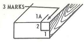
Marks 1 and 2 are for the fence settings. 1A makes it easier to set blade height for the first cut.
Two cuts are required — an into-edge cut (made first), then an into-face cut deep enough to remove the edge strip. Mark one end of board to show the rabbet cross-section and use marks for blade elevation and fence
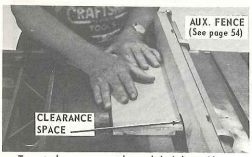
To cut clearance space lower dado below table top and position fence so that aux. fence is about half way over dado. With tool running slowly elevate dado to height desired.
CUTTING A CHAMFER
A simple chamfer is most easily cut with a saw blade tilted to the bevel angle required. When cutting stepped, chamfered edges, however, a dado requires fewer cuts. Stepped, chamfered edges are used to produce raised panels and to decorate table edges.
Cutting must be done along the edge opposite the fence . or the miter gauge must be used, instead. If fence and work are at left side of


settings. Make first (into-edge) cut to exact depth of mark, but when making second (into-face) cut set blade about 1/16 in. below the depth mark so as to remove the edge strip without touching the main workpiece.
A Rabbet With a Dado
Just one — preferably, into face cut is required. Always use a dado wide enough to (or plan last cut of an overlapping series so dado will) overlap the outer edge . and produce a smoother edge. Unless work is too wide always do cutting on workpiece edge opposite the fence. If cut must be made along the edge against the fence, an auxiliary fence must be used — and must be cut out to provide a clearance for the overlapping edge of the dado.

dado it is the top of the edge that is chamfered; if at right side, then the bottom of the edge is chamfered. Use any bevel angle desired. Preferably plan into-face cuts; however, intoedge cuts can be made if more convenient, or if you desire an angle that cannot be cut into-face.

CUTTING A TEN
Tenons having an can be most quick with a dado. Howe fect cabinetmaker with a Tenoning B preferably, using (pages A4 and 51).
With a Dado
Whether tenon has each side is like that a tenon gene that several side-t be needed. Alwa pass of several or accurately as pos

HOW SA

e first (into-edge) cut h of mark, but when d (into-face) cut set '16 in. below the depth remove the edge strip og the main workpiece.
h a Dado
referably, into face d. Always use a dado o (or plan last cut of g series so dado will) ter edge . and proer edge. Unless work always do cutting on e opposite the fence. made along the edge uce, an auxiliary fence — and must be cut out learance for the overthe dado.

top of the edge that is at right side, then the dge is chamfered. Use e desired. Preferably cuts; however, intobe made if more conyou desire an angle cut into-face.


CUTTING A TENON
Tenons having any number of sides can be most quickly and easily made with a dado. However, the most perfect cabinetmaker's tenons are made with a Tenoning Blade ( page 7 ) and, preferably, using a Universal Jig ( pages A4 and 51 ).
With a Dado
Whether tenon has one to four sides, each side is like a rabbet — except that a tenon generally is wider so that several side-by-side passes may be needed. Always make the first pass of several on the inside, and as accurately as possible — then clean

off the outer portion with subsequent passes (which can be done freehand). Preferably produce a tenon with intoface cuts, though on-edge cuts can be used. Note that a Satin-Cut Dado Head can, in some cases, create an undesirable profile unless glue-relief channel(s) is (are) eliminated. To eliminate channels advance successive passes less than 1/8 in.


HOW SATIN-CUT DADO TENONS CAN BE MADE TO APPEAR Unless side(s) of tenon are exposed, as illustrated, Into-the-Face glue-relief channels cannot be seen after assembly. An On-Edge channel will show.
Tenons - With a Saw Blade
For clean, square appearing shoulders always make the shoulder cuts first - to exact depths required - then make the cheek and/or edge cuts, setting the blade about 1/16 in. below exact depth, as for a rabbet second cut ( page 25 ). If you do not have a Universal Jig, use both the miter gauge and the fence ( page 22 ) when making shoulder cuts - and use intoend ripping method ( page 25 ) for the cheek and edge cuts. Or, you can make a tenoning jig ( page 56 ) to hold work for the cheek and edge cuts.

When using a jig (Universal or homemade) there are two methods of assuring accuracy: 1) Clamp the work directly to the jig, then position the jig so as to cut the cheek (or edge) on the side away from the jig. After cutting the first cheek (or edge) turn the work around to cut the opposite one with same jig setting as the first. This method will center the tenon accurately, but the tenon width will be subject to the accuracy of your measurements and the jig setting.


2) When making the first cut use a backing block between the jig and the work and position the jig to cut the cheek (or edge) on the same side as the jig. Have the backing block the exact width of the desired tenon plus the saw-blade width (1/8 in. for a tenoning blade). To make the second cut remove the backing block — with-out turning work or altering the setting. This method will assure a tenon of the exact width desired, but centering of the tenon will depend upon the accuracy of your measurements and the jig setting.

NOTE
If you use two outside dado blades (or a pair of tenoning blades) accurately centered, exact width tenons (up to about 3/4-in. max. width) can be cut as shown. Exact spacing between blades is obtained by using a collar and paper shims.
DADO GAINS A STOPPED GRO SIMILAR SAW
To cut a gain m show end of gain desired depth of with back edge where it rises a Holding workpied block to table against rear edg or, if workpied aligning marks


HANDLING OD
It is sometimes a straight cut cannot be guided gauge (like half such jobs a home ( page 54 ) is ve guide strip at b along the miterthe two parts an top) it can be or be used freeh

between the jig and the ition the jig to cut the ge) on the same side as the backing block the f the desired tenon plus the width (1/8 in. for a the backing block — withork or altering the setthod will assure a tenon width desired, but centenon will depend upon of your measurements ting.

two outside dado a pair of tenoning curately centered, tenons (up to about x. width) can be wn. Exact spacing des is obtained by ar and paper shims.
DADO GAINS AND STOPPED GROOVES OR SIMILAR SAW-BLADE CUTS
To cut a gain mark the workpiece to show end of gain. Elevate dado for desired depth of cut, then align mark with back edge of dado (at the point where it rises above the table top). Holding workpiece thus, clamp a stop block to table or fence butted up against rear edge of workpiece ... or, if workpiece is too long, draw aligning marks on workpiece edge

HANDLING ODD-SHAPED WORK
It is sometimes necessary to make a straight cut on a workpiece that cannot be guided by the fence or miter gauge (like halving a circle). For such jobs a homemade Cut-Off Board ( page 54 ) is very useful. With the guide strip at bottom this jig slides along the miter-gauge groove; when the two parts are reversed (strip at top) it can be guided by the fence, or be used freehand.

and table top at a convenient location. Make the cut as usual, feeding the workpiece until it is stopped by the stop block (or marks are aligned). Stop the dado, then lift work off of it.
To cut a stopped groove arrange a rear stop block (or aligning marks) as above. Similarly arrange a front (starting) block (or marks). Start the tool. Butt front edge of workpiece against starting block (or hold workpiece above dado with starting marks in alignment), then lower workpiece onto the dado. Complete the cut as above.
Exactly the same procedures can be used — with a saw blade — for marking through slots. However, if a deep cut is needed to go through the work, when cutting a blind slot best start with blade only about half elevated. After workpiece has been lowered onto the blade and flat on the table, hold it and elevate the blade until it is cutting clear through.

SAWING CLEAN JOINTING EDGES
A quick way to cut two straight clean edges for jointing is to lock both pieces, with their faces together, in the cut-off board for simultaneous sawing. Also, if using a large-tooth blade to saw plywood or veneer, you can obtain a cleaner cut by placing the workpiece on top of a scrapboard and locking both pieces in the cut-off board for simultaneous sawing.

NOTE: Calculation of angle A requires a trigonometric table (Cot. A = L ÷ Y). However, the following table will suffice for most ordinary requirements. (For angles of 30° or more use miter gauge.)
| Т | A | T | A | Т | A |
|---|---|---|---|---|---|
| 1/4" | 1-1/2° | 3'' | 14° | 8" | 33-1/2° |
| 1/2'' | 2-1/2° | 4'' | 18-1/2° | 9" | 37° |
| 3/4'' | 3-1/2° | 5'' | 22-1/2° | 10'' | 40° |
| 1''1'' | 5° | 6'' | 26-1/2° | 11" | 42-1/2° |
| 2'' | 9-1/2° | 7'' | 30° | 12'' | 45° |
For in-between tapers add a proportion of the indicated rate of increase. For instance: For a 3-1/2" taper add 2-1/4° (1/2 the difference between 14° and 18-1/2°) to get (14° + 2-1/4°) 16-1/4°.

TAPER RIPPING
One Side Only
A taper is a miter cut made lengthwise in a board too long and/or narrow to be guided with the miter gauge. The work can be guided freehand but, if an accurate, straightline taper is desired, a jig should be used. For cutting 0" to 3" tapers on such workpieces as table legs the aluminum Taper Jig (page A4) is excellent. This jig conveniently handles full-length tapers in boards up to 24 in. long - and boards up to 36 in. long can be guided accurately if you use an auxiliary fence to extend approx. 12 to 18 in. out over the table front edge. A homemade jig (page 55) can be designed, if desired, to handle longer boards and/or wider tapers. And, if work is not too awkwardly sized, the miter gauge can be used, as shown, to cut tapers of 7" or larger.
Taper (T) is expressed in terms of inches per foot (1/2" per ft., etc.) – and is the length that line Y will be if line L is 12". A is the taper angle and, as shown, is the same as the indicated angle (A) at which miter gauge would be set if it could be used. The other mitergauge angles B and C (page 18) are also shown. T, X, W or L can be found as follows (see illus. for distances used in examples).
1) 2) 3) 4)

APER RIPP
Two or More S
If two opposite to be tapered. taper the secon ready removed must be compe setting. To ma equal to the first ting; if a differ add in the firstmaking the seco a second edge cut. If second cut edge, the ji ond edge is mad had not been cut equal tapers on a table leg), s taper and cut th side adjacent to the jig setting maining (opposit
Λ
If using prec calculate the posite equal ''6'' for the '
CALC N TWO OPPO
30
ter cut made lengthd too long and/or ided with the miter can be guided freeaccurate, straightsired, a jig should tting 0" to 3" tapers ces as table legs the Jig (page A4) is ig conveniently hanapers in boards up - and boards up to be guided accurately xiliary fence to exo 18 in. out over the A homemade jig designed, if desired, poards and/or wider work is not too awkmiter gauge can be to cut tapers of 7"
erms of inches per foot (1/2" erms of inches per toot (1/2 length that line Y will be if aper angle and, as shown, is be used. The other miter le 18) are also shown. T. X ows (see illus, for dist
48 x 2 = 8 + 8 = 16 × 12 = 4 × 12 = 48

TAPER RIPPING A LONG BOARD
Two or More Sides
If two opposite edges of a board are to be tapered, when using the jig to taper the second edge the wood already removed from the first edge must be compensated for in the iig setting. To make the second taper equal to the first. double the iig setting: if a different taper is desired add in the first-taper jig setting when making the second-taper jig setting. These rules apply only when tapering a second edge opposite one already cut. If second edge is adjacent to a cut edge, the jig setting for the second edge is made as if the first edge had not been cut. Therefore, to make equal tapers on all four sides (as for a table leg), set jig to the desired taper and cut the first side and one side adjacent to it . then double the jig setting to cut the two remaining (opposite) sides.
NOTE
If using preceding formulas to calculate the first of two opposite equal tapers, substitute "6" for the "12".
CALCULATING FOR TAPER WHEN THERE WILL BE TWO OPPOSITE, EQUAL TAPERS


PICTURE-FRAME MITERING -
The four corners of a picture frame (or of a door or any similar frame) are formed by cutting square (45°) miters to make 90° joints. Your miter gauge can be set to cut accurate 45° miters — and with it you generally can do an excellent job. However, if the workpiece is very long or shaped (as many pictureframe moldings are) so that it is difficult to avoid sidewise creeping or wobbling, results may be as shown. Such results can be avoided — even with difficult workpieces — by using a homemade miter board ( page 56 ).

CUT LEFT-SIDE JOINT PIECE AGAINST L SUPPORT, AS SHOWN - CUT RIGHT-SIDE PIECE AGAINST R SUPPORT
32
Mating a Crosscut Miter to a Taper
Sometimes it is necessary to join a crosscut board to a tapered one (for instance, the skirt boards of a table with full tapered legs). If the taper angle (A) is known, simply set your miter gauge to the same (A) angle. Otherwise, make the measurements W1 and W2 as shown, calculate Y then use distance Y to draw the mitercut line on the skirt board.

RESULTS OF CREEPING
First, cut off each piece to length (outside measurement of frame plus twice saw-blade thickness) with straight crosscuts. Second, place each piece (alone) in the miter board, as shown, to miter trim first one end then the other.

HOLD OR BRACE AN ODD-SHAPED MOLDING UPRIGHT WHILE CUTTING

SPI
PATTERN SA
Duplicates
Duplicate strai any desired sha etc.) can be cut a pattern and a p to the fence. Fi to the exact siz using hardboard number of nails so the points w in. to grip the in position. San pattern bottom purpose if you workpiece firmly ing . or yo board (page 29) the fence, positi then elevate the a clearance in t Feed the pattern the guide to cut a

cut Miter to a Taper
is necessary to join a d to a tapered one (for skirt boards of a table red legs). If the taper nown, simply set your to the same (A) angle. ake the measurements s shown, calculate Y the Y to draw the miterskirt board.

OF CREEPING
each piece to length rement of frame plus a de thickness) with cuts. Second, place he) in the miter board, miter trim first one er.

E AN ODD-SHAPED GHT WHILE CUTTING

CHAPTER 5 SPECIALIZED SAWING OPERATIONS
PATTERN SAWING
Duplicates
Duplicate straight-edged pieces in any desired shape (triangle, square, etc.) can be cut accurately by use of a pattern and a pattern guide clamped to the fence. First, saw your pattern to the exact size and shape desired. using hardboard or lumber. Drive a number of nails through this pattern so the points will project about 1/16 in. to grip the workpiece and hold it in position. Sandpaper glued to the pattern bottom also will serve this purpose if you hold the pattern and workpiece firmly together while sawing . or vou can use a cut-off board (page 29). Clamp the guide to the fence, position it over the blade. then elevate the running blade to cut a clearance in the guide, as shown. Feed the pattern and workpiece along the guide to cut each edge, in turn.


Matching Offset Pieces
To make a set of matched, stepped offset pieces use a pattern as above. Make the pattern to the size of the largest stepped piece — and cut this piece. Now, for each succeeding smaller piece, move the fence outward from the blade by the amount of desired decrease. You can either set the blade high enough to saw through the work and the pattern (thus reducing the pattern size with each succeeding piece) . or you can lower the blade to cut through the work while simply scoring the underside of the pattern (as illustrated).

Though intended only for straightline sawing a bench saw can be used to cut uniform, gentle curves. Maximum curvature depends upon blade diameter and height, and workpiece thickness — but on the average may be said to be limited to approximately 2 in. per foot (the approx. curvature on the circumference of a 6-ft. dia. circle). Always use the lowest possible blade setting. Also, make allowance for a resulting saw kerf 1-1/2 or more times normal width, depending upon blade height and desired curvature.
To saw a number of duplicate curves a pattern may be most satisfactory. If only one edge is to be curved, prepare a "concave cut" pattern to be clamped to table top or fence. Either side No. 1 or No. 2 (or both) in the illustration can be regarded as the finished workpiece. To simi-

larly curve the opposite edge of No.1 use the same pattern; but to similarly curve the opposite edge of No. 2, use piece No. 1 as a "convex cut" pattern.
If you can establish a convenient pivot point (a nail driven into a suitable-height sawhorse, or similar), the jig method will save the trouble of preparing a pattern. The jig can be made of scrap lumber. It must be supported level, free to rotate to slide the workpiece on the table top.

SAW TRIMMING A CIRCLE
Circles down to about 4 in. dia. can be shaped by repeated trimming. Draw the circle on your workpiece then saw as close to the circumference as you can by making a series of straight (tangent) cuts. For final rounding, place workpiece on support and rotate it to the blade as shown.

With the homem can saw scrape to make straigh which, after sa decorative table large-toothed bl. bide-tipped ( pag ends are set at straight roundin for taper roundin the settings as l
Anchor the slid a 450 angle to tioned so that will be directly Nail stop blocks jig sliding as d runner to the blu to serve, as sl
DOWEL SPLIT
Cylindrical sto small in dia. the fence without to rotate or rol the cut is spoi split a dowel, su straightedge boa half-rounds, if s larly supported to ter-rounds.


posite edge of No.1 ern; but to similarly edge of No.2, use convex cut" pattern.
blish a convenient driven into a suitorse, or similar), 11 save the trouble ttern. The jig can lumber. It must be free to rotate to ce on the table top.

G A CIRCLE
about 4 in. dia. can repeated trimming. on your workpiece e to the circumferby making a series ent) cuts. For final orkpiece on support e blade as shown.

With the homemade jigillustrated you can saw scrape squares (like 2x2s) to make straight or tapered spindles which, after sanding, will serve as decorative table legs, etc. Use any large-toothed blade, preferably a carbide-tipped ( page A-2 ). Jig adjustable ends are set at identical heights for straight rounding; set one end higher for taper rounding. In any case, keep the settings as low as possible.
Anchor the slide as shown, at about a 45o angle to the blade, and positioned so that workpiece centerline will be directly above blade center. Nail stop blocks to the slide to limit jig sliding as desired. Add a wood runner to the block nearest the blade to serve, as shown, to hold jig in
ROUNDING SQUARE WORK

under the rabbeted slide edge. Check and adjust for freedom of jig movement; but also eliminate any sloppiness of motion.
Start with blade elevated to take a 1/8 to 3/16 in. cut into workpiece lowest point. Do the scraping by sliding the jig from one end to the other, while holding the workpiece to prevent it from revolving. Rotate the workpiece slightly each time you reverse iig movement, and continue thus until the entire workpiece circumference has been scraped. Afterwards, elevate the blade 1/8 to 3/16 in. and again scrape the entire circumference . and so on until spindle is reduced to the roundness and size desired. Delicacy of cut and firmness of motion determine work quality.
DOWEL SPLITTING
Cylindrical stock — especially if small in dia. — cannot be fed along the fence without having a tendency to rotate or roll out of line so that the cut is spoiled. To accurately split a dowel, support it between two straightedge boards, as shown. Even half-rounds, if small, should be similarly supported for slicing into quarter-rounds.


OFF-CENTER CUT

CUTTING COVES covi OPTIONAL CUT TWO COVE MOULDINGS A HALF ROUND TWO CORNER ROUNDS
With your bench saw and a proper blade you can easily create cove mouldings of various designs, or cut coves for other decorative purposes. Preferably use a carbidetipped blade, which will cut sideways if feed is slow and shallow cuts are taken. Or, you can use a chiseltooth combination or a dado head . but the depth and angle of cut must be such that the fronts (not sides) of the teeth will do the cutting. The angle of cut determines the cove shape.

To plan a cove elevate the blade to the height of the finished cove depth desired. Place workpiece on table and angle it with respect to the blade so that cove width will be as desired.


DEPTH OF CUT (D)

ANGLE DETERMINES COVE SHAPE
Clamp a straightedge to the table to guide the workpiece to the blade at this angle. To cut the cove, lower the blade to take no more than a max. cut (preceding) and slide the workpiece slowly along the straightedge to feed it to the blade. Make as many similar passes as necessary to attain the required cove depth.
Work can be speeded by first making two bevel cuts to remove a V-shaped wedge at the center of the cove. This leaves less wood to be removed during the cove-cutting procedure.
CUTTING BOW
Bowl-shaped depr rative purposes, revolving the wo center above the h ing the blade in manner as for c cutting is done alm sides of the tee should be done or tooth (or similar s ... and feeding (h be very slow. A cut will be sha (less than half) will vary only a diameter and fina
If a circle workp be centered for blade by clamping to the table. Fo an arm with a p used. You can re either direction. complete revolut setting, before el crease depth.
If board is not to a Miter-Gauge St a fixed setting, to of each remaining pieces will vary use the stop rod from the blade, side of the gauge.
If desired length more than can be blade and fence, fence to establish However, do not a to contact the fe operation - this stead, clamp a st fence as shown.
If neither above m use a stop block c or to any adjacent


VIDTH OF TOOTH NGLE DETERMINE OF CUT (D)

MINES COVE SHAPE
ghtedge to the table orkpiece to the blade Fo cut the cove, lower e no more than a max. and slide the workong the straightedge to blade. Make as many as necessary to attain ve depth.
NOTE
e speeded by first bevel cuts to rehaped wedge at the e cove. This leaves to be removed dur--cutting procedure.
CUTTING BOWL SHAPES
Bowl-shaped depressions for decorative purposes, can be sawed by revolving the workpiece at deadcenter above the blade while elevating the blade in steps in the same manner as for cove cutting. Since cutting is done almost entirely by the sides of the teeth this operation should be done only with a carbidetooth (or similar swedged-tooth) blade ... and feeding (by revolving) should be very slow. All depressions thus cut will be shaped like segments (less than half) of a sphere – and will vary only according to blade diameter and final depth of cut.
If a circle workpiece is used it can be centered for revolving over the blade by clamping a V-notched guide to the table. For any other shape an arm with a pivot point must be used. You can revolve workpiece in either direction. Make at least one complete revolution at each blade setting, before elevating blade to increase depth.
If board is not too long you can use a Miter-Gauge Stop Rod, adjusted to a fixed setting, to establish the length of each remaining piece (the cut-off pieces will vary in lengths). Always use the stop rod on the side away from the blade, never on the blade side of the gauge.
If desired length of duplicates is no more than can be fitted between the blade and fence, you can use the fence to establish this desired length. However, do not allow the workpiece to contact the fence throughout the operation — this might bind it. Instead, clamp a starting block to the fence as shown.
If neither above method is convenient use a stop block clamped to the table, or to any adjacent stand, tool, etc.


CROSSCUTTING DUPLICATES


CHAPTER 6
MOLDING AND SANDING WITH YOUR BENCH SAW

THE SET-UP
A Molding Head, either the 1- or 3cutter type (page A2), can be mounted in place of the saw blade to cut variously patterned grooves and edgings (rabbets) in much the same manner as a dado. The guard and splitter must be removed, and a Molding Insert is used in place of the regular insert. Work can be guided freehand, with the miter gauge, or along the fence. If the fence is to be used for edge or end molding it must be fitted with an auxiliary fence (page 54) having a cut-out to provide clearance for recessing the head as may be required for partial cutter exposure to the workpiece.
NOTE
Auxiliary should be 1-in. thick with cut-out of same thickness. To make cut-out, fit molding head with your largest cutter(s), lower it below table top, and clamp auxiliary to table in proper position above the head.

Head, except the Wedge Tongue and Groove Set which consists of 6 bits. When ordering single bits for the 1-Cutter Head add the numeral 3 as a suffix to the catalog number (ie: 9-32113, etc.).
CRAFTSMAN CUTTER SHAPES
Turn tool on a vate the revolv highest position iaries, one at fence, will proversatility.
SELECTING YOU
A number of cutte available. By com two or more bits ferent designs can cuts can be planned overlap, to be spa angles to one anoth most popular mold gether with the ca the bits used to cr shown here.
To help the planni signs keep a file r

Turn tool on and slowly elevate the revolving head to its highest position. Two auxiliaries, one at each side of fence, will provide maximum versatility
SELECTING YOUR PATTERNS
A number of cutter-bit shapes are available By combining the cuts of two or more bits hundreds of different designs can be created. The cuts can be planned to just meet to overlap, to be spaced, or to be at angles to one another. Some of the most popular molded designs - together with the catalog numbers of the bits used to create them - are shown here.
To help the planning of molded designs keep a file record of your bit

shapes. Make ink outlines of your bits on 4-in, squares of vellum or tracing paper. Two or more of these papers can be stacked and moved about so that, when you look through them, you can see the resulting design possibilities. If you also make a tracing of any design thus arrived at — with bit numbers noted on it you can at any time duplicate this design.
SHAPES YOU CAN MOID WITH MOIDING HEAD CUTTERS

AN CUTTER SHAPES
WEDGE TONGUE AND GROOVE SET
made in sets of 3 for the 3-Cutter ledge Tongue and Groove Set which When ordering single bits for the the numeral 3 as a suffix to the
9-2303
FLUTE, 1/4" and COVE, 1/2"
FLUTE and 3/16
CLOVER LEAD and SCREEN MOLD
FLUTE, 1×1/2'
1/4-ROUND and COVE, 5/ (DROP LEAF)
1/4-ROUNDS, 3/8" and 3/16" and 1/4" BEAD
COVE, 5/8"
9-3209
5/16
FLUTE 90°
9-3203
9-3204
BASE
9-3204
W
R-
'ER 1/4''
ARD


GENERAL RULES FOR MOLDING OPERATIONS
These are exactly the same as the general rules for dado operations ( page 21 ). Any molding bit will take a fairly wide cut... too wide to cut smoothly if set for full-width groov-ing at more than approx. 1/4 in. of
depth. Make deeper cuts in two or more passes at advanced depths; or, if there is much wood to be removed entirely (not as part of the molding design), remove the excess by sawing it off prior to molding.

THE UNIVERSAL JIG SIMPLIFIES MANY MOLDING OPERATIONS
MOLDING STRAIGHT EDGES
The auxiliary-equipped fence should be used for all straight-line molding along a workpiece edge. Although it is possible to mold along the workpiece edge opposite the fence (in which case a slip can result in over cutting), better work (with no danger of over cutting) is produced by doing the molding along the edge that is against the fence (by pushing the workpiece against the fence as you feed it). Work can be flat on the table or standing on edge (or end), depending upon the way you want the design cut into it. If on edge or end - and if very high - it should be supported (page 25). If end molding a piece too narrow to hold squarely against the fence, use the miter gauge together with the fence to guide it.


Avoid crossgrain molding unless absolutely necessary — it is difficult to prevent splintering the end of the cut (unless a backup board is held tightly against the workpiece so that the cut ends in the backup board). If a piece with corners is to be molded all around, make the crossgrain cuts first — then when the withgrain cuts are made the splintered ends will be removed.

The quickest met triangular blocks of to form a V. An use a pivot point brace clamped to so that the point project down at wo

MOLDING C
ATIONS
leeper cuts in two or t advanced denths: or h wood to be removed s part of the molding to molding
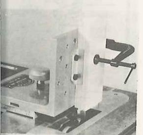
OPERATIONS


molding unless aby - it is difficult to ing the end of the ackup board is held e workpiece so that the backup board). corners is to be d, make the cross-- then when the ande the splintermoved.
MOLDING CIRCULAR EDGES
The quickest method is to use two triangular blocks clamped to the fence to form a V. Another method is to use a pivot point at the end of a brace clamped to the fence or table so that the point (a nail end) will project down at workpiece center.


MOLDING CURVED EDGES
Curved work must be freehand guided. However, by use of the fence or a pivot block to limit the depth of cut. overcutting can be prevented — and you can mold the workpiece all around several times if need be to obtain uniform results.
For any convex curvature simply use the fence. Make a mark on the fence to indicate the top center of the cutter's swing . then continually turn the workpiece as you feed it to keep the fence as nearly as possible tangent to the edge at point of contact (at the mark).
For any concave curvature you can use a pivot block, if only the underside of the edge is being molded so that top part remains uncut . or if you place a pattern on top of workpiece to provide an uncut edge for contacting the pivot block. Feed in the same manner as above.
ORNAMENTAL GROOVINGS
Grooves can be cut parallel to any edge (straight, circular or curved) by use of the appropriate preceding method of guiding the workpiece. Spacing of grooves can be accomplished by repositioning the fence, or by any method used for dado groove spacing (Chapter 3).
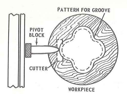
DECORATIVE SPIRAL GROOVES
A length of dowel of 3/4-in. or more diameter can be spiral grooved by use of a short stripping guide and a molding head. Make the guide to hold the dowel loosely enough to allow it to revolve, without wobbling - and no longer than necessary. Start with a chisel-tooth (or similar) blade. Clamp guide to table above - and at an angle (750 or less) to - the blade. Insert dowel with starting end above blade, start tool, and elevate blade to take a 3/16-in. (or deeper, if desired) cut. Release the dowel; if properly fitted in guide the blade will roll it and spiral groove it from end-to-end . or, you can help by twisting it lightly, if need be. The angle of the guide determines the pitch of the spiral, which becomes greater as angle is decreased.
Install the molding head, using bit(s) such as 3204 or 3206. Reposition the guide (as shown) at 900 to the head ... located approx. 2/5 of dowel dia. behind a mark on the insert that is directly above the saw-arbor centerline ... and with a pin (to ride in spiral groove) exactly one spiral spacing to right of a mark at the bit centerline. Feeding from right, rotate work along the guide keeping the spiral firmly engaged over the pin. Best make several light-cut passes, ending with a deep enough cut to serve your purpose.
If a groove of different contour from the workpiece edge is desired (say a cloverleaf shaped groove in a circular workpiece), this can be made by using a pivot block (above) together with an appropriately shaped pattern secured to the top (which would be the underside when finished) of the workpiece.


MAKING STRIP One way to make on strips is to edge board, then to savedge in as thin a If pre-cut strips as these must be for through a Stripping has a cut-out (throw bottom) for the sw and is clamped to curate positioning. to mold thin stripting

A Sanding Plate or can be quickly moun saw to provide all a power disc sand vantage of excellent ing (since the arbor is tilted). Sanding either side . in plate, secure diffe papers to the two for both rough and fi
Work can be guided used for sawing of sliding work betwee sanding disc, positi squeeze the work ver the disc — and a the will result. If using similarly hold work ping — to guarante
FOR COMP OBTAIN SEA
different contour from edge is desired (say a ped groove in a circular is can be made by using above) together with an shaped pattern secured ich would be the undershed) of the workpiece.

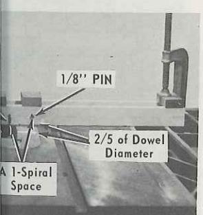
GROOVED DOWEL

One way to make ornamental molded strips is to edge mold a sizeable board, then to saw off the molded edge in as thin a strip as desired. If pre-cut strips are used, instead, these must be fed to the cutter through a Stripping Guide . The guide has a cut-out (through the cover at bottom) for the swing of the cutter, and is clamped to the fence for accurate positioning. Never attempt to mold thin strips without such a guide.

MAKING DOWELS
Either 1/4-in. or 1/2-in. dowels can be cut in four operations using bit 9-2351 and a stripping guide of correct groove dimensions. The strip to be molded must be square, with either 1/4-in. or 1/2-in. sides. When feeding to cut the last (fourth) corner take care to prevent the strip from rolling.
A Sanding Plate or Wheel (page A3) can be quickly mounted on your bench saw to provide all the advantages of a power disc sander, plus the advantage of excellent bevel angle sanding (since the arbor, and not the table, is tilted). Sanding can be done at either side . in fact, if you use a plate, secure different grit sandpapers to the two sides to provide for both rough and finish sanding. Work can be guided in any of the ways used for sawing operations. When sliding work between the fence and
sanding disc, position the fence to
squeeze the work very lightly against
the disc - and a true, straight edge
will result. If using the miter gauge,
similarly hold work - without slip-
ping — to guarantee straight edge
- SANDING OPERATIONS
sanding. If sanding a small piece that does not span the disc, hold it against the front (downward moving) half of the disc rather than the back half. Never press work forcefully into disc . . feed lightly, and let the sanding grits do the work.
FOR COMPLETE SHARPENING INFORMATION FOR ALL TOOLS OBTAIN SEARS BOOKLET "HOW TO SHARPEN" CAT. No. 9-2924
CHAPTER 7 WOOD JOINTING - 32 WAYS
SIMPLE MITER JOINTS -
A simple (450) miter joint, whether flat or on-edge, is best cut with a miter board (page 56), holding the first piece at one side and the other piece at the other side of the board to make the respective cuts. For top-quality cabinetwork use one of the cabinet or thin-rim blades (page A2).

POLYGON MITERS FLAT ON-EDGE
| TIOURE | SIDES | ANGLE |
|---|---|---|
| Triangle | 3 | *60° |
| Square | 4 | 45° |
| Pentagon | 5 | 36° |
| Hexagon | 6 | 30° |
| Heptagon | 7 | 25¾° |
| Octagon | 8. | 22½° |
| Nonagon | 9 | 20° |
| Decagon | 10 | 18° |
| Undecagon | 11 | 16½° |
| Dodecagon | 12 | 15° |
*Can't do as a bevel angle.
SIMPLE MITER FLAT
A polygon is a figure of any number of equal sides. To make such a figure (other than a square) miters of some angle other than 450 are required. Any angle required for a flat polygon can be cut using the miter gauge. The sides of an on-edge polygon, however, must be bevel cut - and the maximum angle is 450 unless you rig a jig to hold work at a greater angle.
SIMPLE MITER
B = 180 ÷ Number of Sides 1/2A = 90 - B; A = 2 x (90 - B)
SLIP-FEATHER JOINT
For flat, simple or polygon miter joints. Use the Universal Jig and Tenoning Blade (or equivalents) to groove the corner. Make triangular wedge to exactly fit the groove.

COMPOUND MIT Any single compou
be cut using bevel gauge or taper jig choice. Simply ke angles and the sa miter-gauge (or ji both pieces. To for sided figure, howe compound angles fo ber of sides and of the sides must be
Planned as shown below at

SPLINED JOINT
For on-edge, sim compound-miter jo ing or similar Bi bevel angle used to groove each piece to heel than to the deep). Make the s the mating grooves

VAYS
MITER JOINTS
80 ÷ Number of Sides 10 – B: A = 2 x (90 – B)
s a figure of any number es. To make such a figure a square) miters of some
than 450 are required. equired for a flat polygon using the miter gauge. of an on-edge polygon, ast be bevel cut — and the ngle is 450 unless you rig
work at a greater angle.
Any single compound miter joint can be cut using bevel and either mitergauge or taper jig settings of your choice. Simply keep the same bevel angles and the same (but opposite) miter-gauge (or jig) angles to cut both pieces. To form a closed, equalsided figure, however, the correct compound angles for the desired number of sides and the desired pitch of the sides must be chosen.
Planned as shown below at left, A and B will be identical. A is a right (outside on top) and B is a left (inside on top) of a compound-miter joint. Or, you can cut A and B in separate operations, cutting B (to leave some scrap) as shown in views at right below.

SPLINED JOINT
For on-edge, simple or polygon or compound-miter joints. Use a Tenoning or similar Blade at the same bevel angle used to cut the joint, and groove each piece as shown (closer to heel than to the point, and not too deep). Make the spline to exactly fit the mating grooves.

Same miter angles – but first one at right, second one at left.
| 4 SIDES | 6 SIDES | 8 SIDES | ||||
|---|---|---|---|---|---|---|
| Pitch | Bevel | Miter | Miter Bevel | Bevel | Miter | |
| 5° | 44¾° | 5° | 29¾° | 2½° | 22¼° | 2° |
| 10° | 441/40 | 9¾° | 291/2° | 5½° | 22° | 4° |
| 15° | 43¼° | 141/20 | 29° | 8¼° | 21½° | 6° |
| 20° | 42° | 19° | 28¼° | 110 | 21° | 80 |
| 25° | 40° | 23° | 27¼° | 13½° | 20¼° | 10° |
| 30° | 37¾° | 26½° | 26° | 16° | 19¼° | 11¾° |
| 35° | 35¼° | 29¾° | 24½° | 18¼° | 18¼° | 13¼° |
| 40° | 32¾° | 32¾° | 22¾° | 20¼° | 17° | 15° |
| 45° | 30° | 35¼° | 21° | 22¼° | 15¾° | 16¼° |
| 50° | 27° | 37½° | 19° | 23¾° | 14¼° | 171/20 |
| 55° | 24° | 39¼° | 16¾° | 25¼° | 12¾° | 181/20 |
| 60° | 21° | 41° | 14½° | 26½° | 110 | 1934° |


END-LAP JOINT
If boards are identical, each tenon should be half of board thickness ... otherwise, make thinnest board tenon half its thickness, then rabbet other board to this depth. When boards are different widths the depth to the shoulder of each tenon should equal width of other board. Use either a regular blade or a dado ( page 7 ). As shown, the Universal Jig makes the on-end cutting easy.
MIDDLE-LAP JOINT -
Same as an end-lap except that joint is not at the ends, and a dado must be used. Each board alone (or, in some cases, both together) can be held by the Universal Jig for cutting.

GROOVED, ON-EDGE MIDDLE LAP
A good joint for use at center of a shelf, which can be same width as, or much wider than, the vertical member. First cut the side grooves in the upright, using a dado as wide as the shelf thickness — and cutting each groove to depth of approx. one-third upright thickness. Use same dado width to cut notch in upright, cutting to a depth no more than half upright width. Notch the shelf with dado of new width required, to a depth to make rear edges of boards fit flush.
TEE- AND CROSS-LAP JOINTS
These laps can be formed in three different ways, depending upon how weight or stress will be applied to the joint. Preferably use a dado for all the cuts, holding work with the Universal Jig.

A strong joint for ends of drawers and where appearance is
BOX JOINT
where appearance is boards up to 5 in. w. Jig makes an easy-to vice. The jig scale spacing the cuts. If
DADO AND RABE
Good principally for bearing cross-memb upright. The one red cut in cross-member upright. The other rabbet cut at crossdeep as the upright's cut more than half th member. The rabl reinforced with glue b
BOX CORNER; HO
The box corner is ext the back of a draw

INT
identical, each tenon of board thickness .... ke thinnest board tenon ess then rabbet other depth. When boards widths the depth to the ich tenon should equal board. Use either a or a dado (base 7). As iversal Jig makes the easy.

ROSS-LAP JOINTS
n be formed in three , depending upon how ess will be applied to ferably use a dado for holding work with the

A strong joint for boxes, the back ends of drawers and similar corners where appearance is secondary. For boards up to 5 in. wide the Universal Jig makes an easy-to-use holding device. The jig scale can be used for spacing the cuts. For wider boards
DADO AND RABBET JOINTS
Good principally for joining a weight bearing cross-member to the top of an upright. The one requires only a dado cut in cross-member the width of the upright. The other requires only a rabbet cut at cross-member end, as deep as the upright's thickness. Never cut more than half through the crossmember. The rabbet joint can be reinforced with glue blocks or braces.
BOX CORNER: HOUSED DADO
The box corner is excellent for fitting the back of a drawer to the sides;


blade cuts, forms the shelf tenon.
extension (page 54) is used. In any
case, cutting is done with a dado of
any width desired (generally, same
width as board thickness) — and two
mating board ends are cut simul-
the housed dado makes a firm shelf-
end joint. Each consists of a rab-
beted tenon (regular blade or dado
cut) fitted into a dado-cut groove.
Do not make either cut more than
Similar to the housed dado, this joint
locks the shelf against pulling free,
and will support more weight than a full dovetail joint. Cut the mortise
with a dado, then use a dovetail bit to rout out the angle at top side. A
beveled rabbet. made by two regular
half through board thickness.
DOVETAIL HOUSED DADO

BOX CORNER
taneously.
HOUSED DADO DOVETAIL DADO

MILLED DADO BOX CORNER -
This joint leaves a minimum of end board showing. If the two grooves and the end lap are of equal thickness a very strong joint is provided; making the end lap thinner weakens the joint but improves the appearance.

RABBET-MITER JOINT
Easier to make than the preceding, this joint can be cut entirely with a regular blade. It is neat and strong, especially if a spline is added, as shown below (the spline grooves need be only as wide as your regular blade thickness).


¥
1/5X
1/2Y->
JOINT

LOCK-MITER JOINT
This joint combines the neat appearance of a mitered corner with the strength of a dado corner. The mitered portion should not exceed half the joint. as shown - or, preferably, less. Do cuts 1 and 2 with a dado and 3 through 6 with a regular blade (making 5 and 6 at a 450 bevel angle, with boards on end).

LOCK JOINT
Best made entirely with a dado this is one of the firmest - in all directions - of the box corner joints. It has to be assembled by sliding the two boards together, and does not require gluing if there are overlapping pieces at top and bottom to prevent them from sliding apart.

COGGED JOINT -
Reinforcing strips a Cut the groove - w the reinforcing stri the slots in the fra

All tenons can be cu regular saw blade (pa dado (page 27). The tenon should be abou piece thickness, and a penetrate 2/3 to 3/4 piece.
One of the mortises of all others require dri way to drill a mort drill press with a M of proper size, drilli depth and drilling as m (square) holes as need width. Work must be to the drill-press tabl press depth gauge sho
RABBET-MITER JOINT
COGGED JOINT -
Reinforcing strips are often fitted to main frame members in this manner. Cut the groove — with a dado — in the reinforcing strip, then rout out the slots in the frame member and

square their corners with a hand chisel.
LOCK-MITER JOINT
joint combines the neat rance of a mitered cornth the strength of a dado r. The mitered portion Inot exceed half the joint, own — or, preferably, Do cuts 1 and 2 with a and 3 through 6 with a tr blade (making 5 and 6 450 bevel angle, with s on end).

LOCK JOINT
nade entirely with a dado one of the firmest — in rections — of the box c joints. It has to be ased by sliding the two s together, and does not re gluing if there are pping pieces at top and to prevent them from g apart.


- TONGUE-AND-GROOVE JOINT - This is the most used joint for floor-
ing and siding. The groove can be cut with a dado and the tongue can be cut as a centered, 2-faced tenon (made by cutting rabbets at the two sides). However a Molding Head with tongue and groove bits ( page 38 ) will do the job faster and better. If a Universal Jig is used the same setting will position all pieces whether cutting grooves or tongues.


- GLUE JOINT -
A quickly made joint that can be made very firm if cross-member is both glued and nailed (or screwed) to the end-member. Use the Universal Jig to cut the end member, with the member's outer side against the jig. Use miter gauge and fence ( page 22 ) to cut the cross-member, outer side on top.

MORTISE AND TENON JOINTS -
All tenons can be cut either with a regular saw blade ( page 28 ) or with a dado ( page 27 ). The thickness of a tenon should be about 1/3 the work-piece thickness, and a mortise should penetrate 2/3 to 3/4 into its work-piece.
One of the mortises can be dado cut; all others require drilling. The best way to drill a mortise is to use a drill press with a Mortising Chisel of proper size, drilling to the exact depth and drilling as many overlapping (square) holes as needed for the tenon width. Work must be firmly clamped to the drill-press table, and the drillpress depth gauge should be used.

If you do not have a mortising chisel, use a twist drill or wood bit the same diameter as the tenon thickness, drill a straight-in-line series of slightly overlapping holes to depth . then finish squaring the corners and straightening the sides with a chisel. Or, a router is excellent for mortising.
1. Open Mortise and Tenon
One member has a 2-faced tenon, generally centered; the other has a mating, in-end dado slot.
2. Simple Mortise and Tenon
One member has a 3- or 4-faced tenon (3 preferred for greatest strength) which should penetrate 2/3 to 3/4 of the way into other member.
3. Haunched Tenon
This is used where added tenon strength is desirable and partial exposure on top is not objectionable.
4. Concealed Haunched Tenon
Like above, but no exposed top. Use a chisel or hand saw to cut the sloping mortise top, after drilling the straight part.
5. Long-and-Short-Shoulders Tenon
This joint combines tenon solidity with the extra weight bearing strength of a rabbet joint. A 3- or 4-faced tenon can be used ... with one face cut deeper to mate with the rabbet cut in the other member.
6. Molded and Rabbeted Tenon
This is a simple mortise and tenon (3- or 4-faced) made in boards previously rabbeted and edge molded. A number of decorative variations may be made. To make the edging continuous around the corner as shown, remove a portion of the one edging and bevel the mating faces at 45°.
7. Bare-Faced Tenon
This is a variation of number 2 in which the tenon has only two faces.
8. Mitered Tenon
Much used in table construction. Each joint is a simple mortise and tenon with the tenon end mitered at 450, as shown. The two mortises meet at 900 inside the vertical (leg) member. Mitering of the tenon ends allows for deeper tenons.
9. Through Wedged Tenon
A joint with exceptional resistance to pulling apart. The two ends of the mortise are sloped outward to hold the wedges, which are about half the tenon in length.

WOR SAWDUST
Make sawdust bin of 1" Cut all pieces and preasse Detach hardboard pieces A, the chute D (leaving it (leaving 2 rails F fasten motor and motor mount from bevel setting. Remove nu to bench. Fit tail of pieces and flatten the two pieces ti in through back of saw to saw to bench with bolts pa (adjusting bench rails as r piece A to front tray rail. can't be fastened to rear ro to rear of rear rail. Lift c and secure it to pieces A tray.
Vac hose (tank-end fitting opening for operation of ve or, if this opening is cov
ed Tenon
ariation of number 2 in non has only two faces.
Tenon
in table construction. s a simple mortise and he tenon end mitered at wn. The two mortises inside the vertical (leg) fitering of the tenon ends exerct tenons.
Wedged Tenon
exceptional resistance to ext. The two ends of the sloped outward to hold which are about half the eth.
CHAPTER 8
WORK HELPERS FOR YOU TO MAKE
SAWDUST BIN AND STORAGE FOR BLADES AND ACCESSORIES
Make sawdust bin of 1" lumber and 1/8" hardboard. Cut all pieces and preassemble – with screws or nails. Detach hardboard pieces A, B and C – and also detach the chute D (leaving it assembled) from the tray E (leaving 2 rails F fastened to tray). Remove belt, motor and motor mount from saw and crank blade to 45° bevel setting. Remove nuts and bolts that attach saw to bench. Fit tail of piece A down through tray opening and flatten the two pieces together . then angle them in through back of saw to fit tray in place. Reattach saw to bench with bolts passing through tray bolt holes (adjusting bench rails as required to do this). Secure piece A to front tray rail. Fit piece B in place (it can't be fastened to rear rail) . then secure piece C to rear of rear rail. Lift chute assembly up into place and secure it to pieces A and B and to underside of tray.
Vac hose (tank-end fitting) can be inserted into chute opening for operation of vac while saw is in use . or, if this opening is covered (or omitted) and bottom
plate G is removed, a box or paper bag can be used to catch sawdust. Provide a 3/8-in. plywood shelf (as illustrated) to fit onto bottom rails of bench to hold box or bag.
The miter gauge, fence, guard and splitter and other accessories (illustration shows a taper jig, universal jig, protractor and dado insert) can be conveniently hung below grid extension as shown... by using bolts and hooks (easily made of bar aluminum) to hold them. Install a #10 screw in end of miter-gauge slide and in fence rear end to engage in their hooks.
A convenient tray to hold bushings, chipper blades, etc. can be fitted into top of bench in front of saw. Make it of 1'' lumber and 1/8'' hardboard. With the same materials, glue assembled, you can also make a holder for extra blades – using as many plates (A) of 1/8'' hardboard and separators (B) of 1/4'' hardboard as needed. By adding a lumber brace at back you can fasten this to front or side of bench, resting on the pluwood shelf.


size as desired.
Space the two guide strips to slide in the miter-gauge grooves. Nail or flush-head screw them in place parallel to the plywood edges and equidistant from them. Nail or screw the two top boards to plywood to meet (at 90°) at center of plywood. Guide the jig into revolving saw blade to cut the saw kerf.

Use 1" boards with dimensions as desired. Make fence opening so that jig will fit over the fence down onto table top, and will slide along the fence. Make blade cut-out so that blade will recess into jig face against which workpiece will be clamped — with the stop block to help hold it upright.


 Instruction Guides")


 Loading...