

HOW TO SHARPEN

50*
INDEX
CUTLERY
| Butcher knives2 | 8 |
|---|---|
| Hair clippers | 9 |
| Pocket knives2 | 7 |
| Razors | 8 |
| Scissors, shears2 | 8 |
EDGE CUTTING TOOLS
| Auger bits | 6 |
|---|---|
| Axes, hatchets | 6 |
| Cabinet scrapers | 5 |
| Draw knife | 6 |
| Plane irons | 2 |
| Wood chisels | 2 |
GARDEN TOOLS
| Grass hooks | 1 |
|---|---|
| Hedge shears | 1 |
| Hoes | 1 |
| Scythes | 1 |
| Spades | 1 |
METAL CUTTING POWER TOOLS
| Lathe bits | 2 |
|---|
METAL CUTTING TOOLS
| Cold chisels | • | • | • | • | . 26 | ||||
|---|---|---|---|---|---|---|---|---|---|
| Nippers, carpenters | • | • | • | . 26 | |||||
| Pliers | • | • | • | • | . 26 | ||||
| Tin snips | • | . 26 | |||||||
| Twist drills | • | • | . 24 |
SAWS
| Bandsaws | , | 1 | . 17 | ||||
|---|---|---|---|---|---|---|---|
| Circular |
• |
• |
• | . 14 | |||
| Cordwood |
• |
• |
i. | • | • | • | . 16 |
| Hand | . 8 | ||||||
| Timber | .13 |
SHARPENING EQUIPMENT
Care of....................................
WOODWORKING POWER TOOLS
| Dado cutters1. | 5 |
|---|---|
| Jointer knives | 8 |
| Shaper cutters1 | 9 |
| Wood lathe chisels | 0 |
HOW TO SHARPEN

MECHANICS * SHOP MEN FARMERS * STUDENTS HOME CRAFTSMEN
FIRST EDITION

Handbook
COPYRIGHT 1943 by SEARS, ROEBUCK AND CO. CHICAGO

How to Sharpen
Much of the trouble experienced by those who work in wood is caused by using tools which are incorrectly sharpened or adjusted.
The sharpening of a plane iron or a chisel looks so simple that many of us think the job cannot possibly be done wrong. Then, when our work doesn't come up to our expectations, we assume we are lacking in skill. The trouble in most instances is not a lack of skill, but is directly traceable to improper tool sharpening.
Equipment Required
In sharpening edge-cutting tools, such as plane irons, wood chisels, draw knives and cabinet scrapers, you need a grinder, preferably powerdriven, fitted with an aluminum oxide wheel (made by fusing bauxite clay in an electric furnace) of medium grit, and a combination oilstone, either aluminum oxide or silicon carbide (made by fusing coke and sand), with medium grit on one side and fine grit on the other.
Safety Precautions
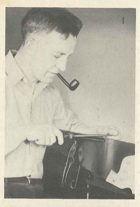
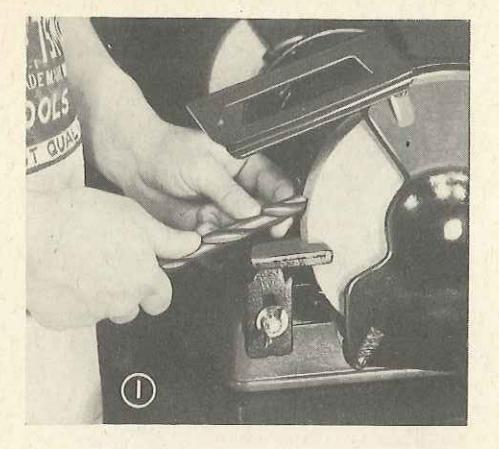
On jobs where wheel guards can be used, be sure they are in place. When grinding without guards, wear a pair of safety goggles with shatterproof lenses, like the ones shown in Fig. 1, to protect your eyes.
Wood Chisels and Plane Irons
The procedure in sharpening plane irons and wood chisels is essentially the same, so we'll discuss them together in the following paragraphs.
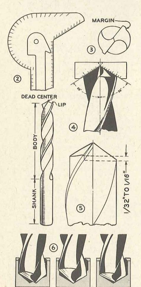
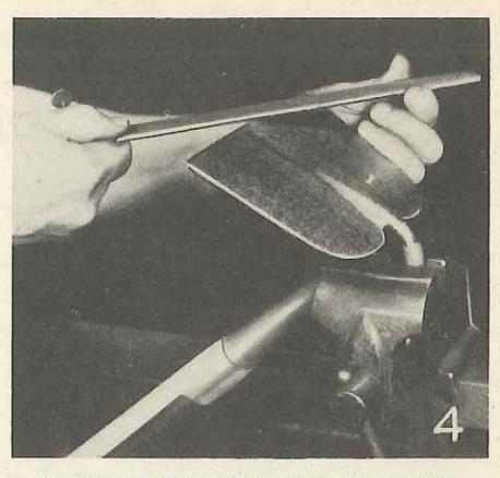
The hist step is to check the squareness of the cutting edge, Fig. 4, and to determine if the tool needs grinding, or if honing will be sufficient. If the cutting edge is out of true, or is subject to any of the trouble shown in Fig. 5, a complete sharpening job will be required.
Grinding
Grind the cutting edge until all nicks are removed and it is properly squared up. Place
MOOTHING
Edge-Cutting Tools
the tool on the tool rest, beveled side up, as in Fig. 2. Press it against the wheel lightly. Dip it in water often to prevent all chances of removing the temper.
The cutting edge on a jack plane iron should be rounded slightly, and on a smoothing plane, the iron should be ground straight and the corners rounded to keep them from making grooves in the wood. Both are shown in Fig. 6.
For the bevel grinding, raise the tool rest and adjust it so a plane iron, when held against it will be ground at an angle of approximately 30 degrees, center detail, Fig. 6. The angle of the bevel may be checked by using a "T" bevel, Fig. 3. To set the bevel, either place it over a plane iron you know is sharpened properly, or use a protractor. Grind toward the cutting edge and continue until a wire edge is formed and the entire bevel is shiny and even.
In grinding the bevel as smiry and even. In grinding the bevel on a wood chisel, the length of the bevel depends somewhat on the purpose for which the chisel is intended. A short bevel, say ¼-inch long, makes a tool suitable for heavy cutting of hard wood. If you're going to use the chisel for paring soft wood, a bevel of ¾-inch will prove more satisfactory. Either measure the bevel with a ruler or check it with a "T" bevel, Fig. 3, the "T" bevel being set by placing it over a properly-ground chisel.
Fig. 11 shows a tool-grinding clamp that can be assembled in a short time from 1/8 by 1 inch flat iron and a length of 1/4-inch rod. To operate the clamp, slip a tool between the two bars and adjust it until the tool is held on the grinding wheel at the proper angle. Once adjusted, the wing nuts are tightened and you can go right ahead with the sharpening.
Honing
After grinding, the next step in bringing either a wood chisel or plane iron to a fine cutting edge is to hone it on an oilstone. You can use either a


In honing, all movement should be at the elbows. The wrists should be kept rigid.

Removing wire edge formed by honing.

An old caster, stove bolt, washer and nut are all you need to assemble the sharpening jig, Fig. 10.

fine stone or the fine side of a combination stone. You don't hone the entire bevel, but instead start a new short bevel at a little greater angle than the ground bevel. The angle at which a plane iron should be held while honing is approximately 35 degrees as shown in the center detail, Fig. 6.
Place the stone on a flat surface, or in a vise, apply a few drops of oil and grasp the tool firmly with both hands, Fig. 7. In rubbing over the stone, it is essential that you hold your hands steady. To avoid the tendency of the tool to rock, your wrists must be kept rigid so all the movement is at the elbows. Move the tool slightly from side to side over the entire length of the stone, with most of the pressure on the forward or "toward the edge" stroke. Occasionally turn the stone end to end.
Figs. 9 and 10 show a simple jig for maintaining a plane iron at the proper angle while honing, assembled from an old caster, stove bolt, washer and nut. Such a jig is handy for home craftsmen and others who have a small amount of sharpening to do.
Fig. 8 shows how the wire edge, formed by honing, may be removed. The tool is laid flat on the stone with the face-side down and is moved back and forth over the stone a few times. Care must be taken to prevent the tool from being lifted and a bevel formed on the wrong side. Another way to remove a wire edge is to draw it through a piece of soft wood.
The procedure just described, if carefully followed, will put a plane iron or chisel in good shape for most kinds of work.
The craftsman that is particularly "fussy," however, may carry the sharpening still another step and strop his tools on leather. A simple leather hone is shown in Fig. 12. This is made by gluing a piece of leather belting with the hair

side up, onto a wood block. In stropping, the action is opposite that of sharpening. You work away from the cutting edge, not against it.
Tests for Sharpness
You can readily determine if an iron or chisel is sharp by holding it up to a bright light. A dull edge will reflect light, while a sharp, keen edge will not.
Another way to test an edge-cutting tool is to allow it to rest on your thumbnail, supporting its own weight. "Biting" of the tool indicates you have done a good job of sharpening. Failure of the blade to bite indicates that the iron is in need of additional sharpening.
Care of Plane Irons and Chisels
Between jobs a plane should have the iron lifted so it will not be dulled. On the job some provision should be made to keep the iron off the bench. Fig. 13 shows how a slat nailed to a workbench will keep the cutting surface from hitting the bench.
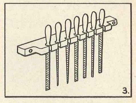
Chisels are preferably kept in a rack, as shown in the drawing, Fig. 14. In cases where it is
NOTE: The instructions given in this book do not necessarily represent the only proper ways to sharpen tools, cutlery, etc. Sharpening methods described are used by a representative group of experts, and will be found correct and helpful for those who seek practical information on sharpening.

necessary to carry them in a box with other tools, the cutting edges may be protected with pieces of adhesive tape.
SHARPENING CABINET SCRAPERS Remove Nicks
A cabinet scraper is a low priced tool which can be used for everything from scraping paint off an old kitchen table to smoothing of the finest cabinet work. Scrapers are of two types; one type has a square edge, the other a beyeled edge.
The first step in sharpening a square-edge scraper is to remove nicks and even up the cutting edges on an oilstone or grinder. Small nicks in the blade may be removed on an oilstone. Use a grinder to remove large nicks. If the top surface of the stone has been hollowed out on previous sharpening jobs, it is best to turn it over and whet on the side, as shown in the photo, Fig. 15.
Draw-File Edges
Next, place the scraper in a wood vise. Grasp a file with both hands, as shown in Fig. 16, and


draw-file the edges at right angles to the face. File on the push strokes and lift the file on the return strokes. Great care should be taken to keep the file true on the surface of the scraper. Continue with the filing until a burr, or wire edge, forms on the cutting edge. To remove the wire edge lay the scraper flat on an oilstone, and give it a few strokes first on one side, then on the other, as shown in Fig. 18
Form Cutting Edge
The actual cutting edge is formed by turning the edge of the scraper to an angle of about 15 degrees with a burnisher—a tempered steel rod with a blunt point on one end and a handle on the other. If you don't happen to have a burnisher, you can do a fair job with a nail set.
Place the scraper in a vise, put a couple of drops of oil on the surface to be turned, bear down on the burnisher, and pull it toward you, as shown in the detail, Fig. 17. The first stroke should turn the edge at approximately 10 degrees and the final strokes at about 5 more degrees, or a total of 15 degrees. A scraper, if properly sharpened, will remove not only wood dust but fine shavings. It can even be used on hardwood veneers without tearing the wood. A cabinet scraper that hasn't been abused in use may be reconditioned several times with a burnisher, before additional grinding or whetting is required.
BEVEL-EDGE SCRAPERS
To put a keen edge on a bevel-edge scraper follow the method given for plane irons, pages 2 and 3, to bring the bevel to an angle of about 45 degrees. Then turn the edge with a burnisher, the same as with a square-edge scraper. If you turn the edge too much with the burnisher, you can raise it by drawing the point of the burnisher along the turned edge, under the burr.
In sharpening cabinet scrapers, as in sharpening most other edge-cutting tools, a little practice is required to get the knack of sharpening which is essential to turning out a first-class job.

SHARPENING DRAW KNIVES
A draw knife that is in bad shape should be evened up on a grinder. Be careful to maintain the original bevel while grinding. After grinding, sharpening of the cutting edge is completed by using a combination oilstone. The knife is placed in the position shown in the photo, Fig. 19. The coarse side of the stone is used first, the stone being moved back and forth across the edge to form a bevel a little shorter than the one made by the grinder. Finishing touches are added by using the fine side of the stone.
SHARPENING AXES AND HATCHETS
Ordinarily an axe is not ground to a straight level like a plane iron, but is rounded. On a job of splitting wood, an axe blade that is thick just back of the cutting edge works best. A thick bevel is formed by holding an axe against the wheel at a short angle. In chopping, particularly on thin stock, a thin blade, formed by holding the axe on the wheel at a greater angle, is preferable.
The shaping of the blade may be done on either a grindstone or high speed power grinder. The blade is finished and maintained by using a
stone, preferably of silicon carbide.
In sharpening a hatchet, it's best to maintain, as nearly as possible, the original bevel, unless the hatchet is to be used for a purpose other than the one originally intended. In whetting with a stone, Fig. 21, the axe or hatchet is held still and the stone is moved back and forth over the surface to do the sharpening. Several sizes and types of stones are available, one of the most popular being a round, combination stone that can easily be carried in an overall pocket.
SHARPENING AUGER BITS
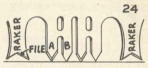
An auger bit in good shape should carry itself into the wood without pressure on the brace. Parts of an auger bit are shown in Fig. 24. If the chips are uneven, some thick, some thin, there is probably something wrong with one of the cutters. If the edges of the chips are rough, or the hole is not smooth, the spurs are not working satisfactorily.
To do a good job of sharpening and renewing auger bits you will need a thin file, with one smooth edge. A special auger bit file costs but little.


Parts that require sharpening are the tops of the cullers and the inside of the spurs , both shown in Fig. 24. To sharpen the cutters, proceed as in Fig. 20. The trick is to file off the same amount from each cutter and to maintain the original bevels as nearly as possible. Proceed carefully, taking a few strokes first on one cutter, then on the other. Filing should be stopped when a fine wire edge appears. The wire edge is removed by touching the edge lightly with the file on the other side. Don't file on the underside other than to remove the wire edge, as this will keep the cutters from feeding into the wood.
Fig. 22 shows the sharpening of the spur. Sharpen at both the front and back. Sharpening the back cutting edge of spur makes it easier to remove the bit from a finished hole. Be careful not to reduce the thickness of the spurs at the base.
Keep away from the outside of the bit, as taking off metal there will make it crowd in the hole.
Damaged threads on the screw point of an auger bit can be improved by running the edge of a triangular file around the threads
Auger bits may also be sharpened with a


small, fine stone, following the method just described for filing.
Care of Auger Bits
To get the most out of auger bits they must be kept free from rust and the cutting edges protected from other tools. If a bit does rust, Fig. 25 shows a practical way to remove it. A small rope is saturated with oil or glue, sprinkled with emery dust, wound around the bit and drawn back and forth. Badly rusted bits can be cleaned up by replacing the abrasive wheel on a grinder with a fine wire scratch wheel and using it to buff off the rust. Be sure to wear shatterproof gogeles to keep flying particles out of your eyes.
A bit that is bent out of shape may be straightened as shown in Fig. 23. A hardwood block is used as a support, and a short block pounded against the bit. Rolling the bit on a flat surface will enable you to determine when it is straight.
The center detail, Fig. 24, illustrates a simple bracket for a wall tool panel, and the detail at the right, Fig. 24, shows how a cork can be used to protect the spurs, cutters and screw of a bit, if it is necessary to carry it in a box with other tools.


SAW SHARPENING
HAND SAWS
There are two general types of handsaws— "crosscut" for cutting across the grain of wood and "rip" for cutting with the grain of wood. See Fig. 7. The difference in the two saws is in the shape of the teeth. A crosscut saw has the teeth filed at an angle that cut like knives, and a rip saw has the teeth filed straight across the saw at right angle to the blade that cut like chisels. Both types are shown in Figs. 5 and 7.
A saw will not give good service or cut correctly unless the teeth are of the same length, properly shaped and properly set.
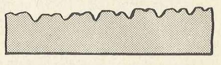
It is unnecessary to reset the teeth of a saw every time it needs sharpening, and a saw ordinarily may be filed at least four or five times before it needs resetting. In filing a new saw every effort should be made to preserve the original shape of the teeth. In cases where saw teeth have been damaged to the extent that the original shape is gone, Fig. 9, it's best to have the saw retoothed at the factory.
Jointing Saw Teeth
If the teeth of a saw are uneven or incorrectly shaped, the top edges must be filed down to the same level before sharpening. This is called jointing.
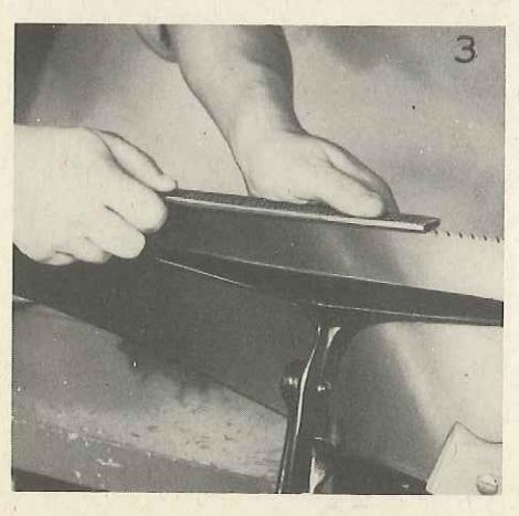
Place the saw in a clamp. Use a regular saw clamp as shown in Fig. 1, if available. If not, you can fit the saw between two boards in a wood vise, as shown in Fig. 4. Run a mill file lightly back and forth the length of the blade, Fig. 3; or use a regular saw jointer, as shown in Fig. 2. The jointer is preferable, because it holds the file squarely on the teeth edges and eliminates all chances of tipping and rounding the teeth.
Under ordinary circumstances, filing is continued until the file touches the top of every tooth. On an especially bad job where the teeth are very uneven, it is best not to make them all the same height in one jointing. Joint only the highest teeth first, then shape—not sharpen , these teeth. Then joint all teeth of saw to same height.
A bright light arranged so the light falls on the teeth will enable you to determine which points have been touched by the file.
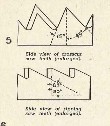


7-point crosscut teeth.
51/2-point rip teeth

When saws have been abused so the teeth are shaped like the ones shown in these drawings they need retoothing at the factory.

Second position for filing
crosscut hand saws.
teeth must be all alike in size and shape to cut equal amounts of wood and make the saw operate smoothly. When all the teeth have been properly shaped and jointed you're ready to set them.
The teeth of a hand saw should be set before sharpening to avoid injuring the cutting edges with the set.
Setting Saw Teeth
The purpose of setting saw teeth, that is, springing over the upper part of each tooth, one to the right, the next to the left, the entire length of the saw edge, Fig. 7, is to make the saw cut a kerf slightly wider than the thickness of the blade, to give clearance and prevent friction which would cause the saw to bind and be hard to pull.
Looking from back of saw. Shows how teeth when set, extend beyond edge of blade
Shaping Saw Teeth
For best results gullets or recesses between saw teeth must be of equal depth. The fronts and backs of all teeth must have the proper shape and angle (see Fig. 5) and the teeth must be uniform in size.
To shape the teeth on a saw, either rip or crosscut, that has been jointed down considerably, place the saw in the clamp, with the handle at the right. The bottoms of the gullets should be ½-inch above the jaws of the clamp; allowing more of the teeth to project will cause the file to chatter or screech, and dull the file quickly.
Use a slim-taper, triangular-shaped file, which suits or fits between the teeth. The following table indicates the length of file needed; the length automatically taking care of the size of the file
5, 6-point crosscut saw, use 7-inch file
5, 51/2, 6-point rip saw, use 7-inch file
7, 8, 9-point crosscut saw, use 6-inch file
7-point rip saw, use 6-inch file
9, 10-point crosscut saw, use 51/2-inch file
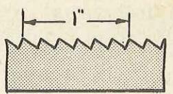
To determine the point of a saw, where the figure is not given on the blade, count the number of tooth points to the inch, measuring one inch from the point of any tooth, as illustrated in Fig. 8. In most rip saws, 6 points and coarser, the teeth at the point are finer than the teeth in the balance of the blade; therefore in measuring rip saw teeth be sure to take the regular teeth at the butt of the blade close to the handle.
Place the file well down in the gullet or space between the teeth, and file straight across the saw at right angle to the blade. Use long, even strokes; cut only on the forward stroke and raise the file each time on the return stroke. If the teeth are of unequal size press the file against the teeth having the largest tops, until you reach the center of the flat surface made by jointing. Then, move the file to the next gullet, and file until the balance of the top disappears and the tooth has been brought to a point. Keep in mind that the

As previously mentioned, it's unnecessary to reset the teeth of a well-tempered saw every time the teeth need a slight sharpening. Fig. 6 shows how a saw looks that has plenty of set and simply needs sharpening.
If setting is required, it makes no difference whether the saw is fine or coarse, the depth of the set should not go lower than half the length of the tooth. If the set runs deeper, it is almost sure to spring, crimp or crack the blade, if it does not break out the tooth.
A saw that is properly taper ground when manufactured, especially one with fine teeth, requires but little set, for the blade, being of uniform thickness the entire edge of the teeth, tapers thinner from cutting edge to back and also tapers from butt to point, providing most of the clearance necessary for easy running. In setting a handsaw, a pin punch and hammer are sometimes used, but the usual practice, outside a saw factory, is to use a set as shown in Figs. 13 or 14. Regular saw sets are preferable as they can be adjusted to bend each tooth at the proper place and just the right amount.
the number of teeth per inch of your saw, and set the anvil pointer of the set to the same number, Fig. 16. Next, adjust the gauge screw under plunger, shown clearly in the photo, Fig. 12, so saw blade passes easily between end of screw and anvil.
Starting at one end, set each alternate tooth by pressing lever, Figs. 12 and 15. The direction of set is correct when thin cutting edges of teeth are bent outward. Continue until you reach the end of the saw then reverse the direction of the saw in the vise and set remaining alternate teeth in the opposite direction.
For unusually hard, dry wood on both rip and crosscut saws, reduce the amount of set. Adjust the anvil pointer to a number higher than the number of teeth per inch of the saw on which you are working.
For soft, wet wood the amount of set should be increased. Adjust the anvil pointer to a lower number than the number of saw teeth per inch.
purposes around a farm should be given more set than a saw used by a carpenter on a building

construction job.
In setting teeth, particular care must be taken to see that the set is regular. It must be the same width from end to end of the blade, otherwise the saw will not cut true; it will run out of line and the cut will be "snaky." Sometimes complaints have been made that a saw is soft and will not hold an edge, when the main trouble is the irregularity of the width of the set.
Filing Crosscut Hand Saws
There are a variety of shapes of teeth, variation in angles, bevel, etc., each being adapted for special work, but the saw user, other than the most experienced craftsman who knows from experience the type of set he prefers, will do well to keep the original form and shape of the teeth for saws in ordinary use.
It's important to use the proper kind of file as discussed under "Shaping Saw Teeth," and to fasten the saw clamp so the top edge is in line with your elbows as previously discussed.
Place the saw in the filing clamp with the handle at the right and the bottom of the gullets 1/8inch above the jaws of the clamp. It will assist you to file a saw properly, if at the start you pass a file lightly over the tops of the teeth just as instructed under "Jointing Saw Teeth" to form a very small flat top on each tooth. This provides a guide for filing. Another way to tell which teeth have been filed is to smoke them slightly with a lighted candle before starting out. This will make it easy to see the fresh file cuts.
Stand at the position as shown in Fig. 10, page 9. Start at the unhandled end of the saw. Pick out the first tooth that is set toward you. Place the file in the gullet to the left of this tooth. Hold the file directly across the blade. Then, swing the file handle toward the left, letting it find its own bearing against the teeth it touches. While filing hold the file level, do not allow it to tip upward or downward, and be sure the file sets down well into the gullet. The file should cut only on the push stroke. It files the tooth to the left and the tooth to the right at the same time. Proceed slowly. Better still, practice on an old saw of no value, if you have one, until you get the knack of handling the file.

It will help the beginner if he will first observe the shape and bevel of some of the unused teeth that can generally be found near the handle end of a saw. If these teeth are shaped as they were when the saw left the factory, they will serve as a guide.
File each tooth until you cut away one-half of the flat top, or smoked portion you made as a guide, then lift the file from the gullet. Skip the next gullet to the right, and place the file in the second gullet toward the handle. Repeat the filing operation on the two teeth the file now touches, being careful to file at the same angle as before. Continue this way, placing the file in every second gullet, until you reach the handle end of the saw.
Study "Fig. 11, page 9," before you proceed further. Turn the saw around in the clamp with the handle to the left. Take the position shown, Fig. 11, Page 9. Place the file in the gullet to the right of the first tooth set toward you—this is the first of the gullets you skipped when filing the other side of the saw. Turn the file handle to the desired angle toward the right. Now file until you cut away the other half of the flat top made on the teeth as a guide, and the teeth are sharpened to a point. Continue this, placing the file in every second gullet, until you reach the handle.
FILING HAND RIP SAWS
With but one difference, rip saws are filed like crosscut saws. They are filed with the file held straight across the saw, at a right angle to the blade.
Place saw in clamp with handle toward the right. Start at the opposite end. Place the file in the gullet to the left of the first tooth toward you. Continue placing file in every second gullet and filing straight across. Remember that the points, not the edges, do the cutting. When the handle of the saw is reached, turn the saw around in the clamp. Start at the unhandled end again, placing the file in the first gullet skipped when filing from the other side. Continue to file in every second gullet until handle-end of saw is reached.

In reading this part of the saw-filing instructions, the inexperienced filer may be tempted to save the trouble of turning the saw around in the clamp and try to file all teeth from the same side of the blade. Don't do it—this practice is one of the things that makes saws run to one side. This should never be done either with a rip saw or with a crosscut saw.
Finishing with an Oilstone
After completing the filing job, it's a good idea to lay the saw flat on a bench and run an oilstone very gently over the sides of the teeth, Fig. 17. This will correct small inaccuracies in setting, remove any burrs or wire edge that may be present, and make the saw cut more smoothly. The same treatment will usually help a saw that "runs."
Care of Saws
A saw can't be expected to give best results unless it is kept free from rust and every precaution taken to protect the cutting edge from damage. Don't lay a hand saw flat on a work bench when you are through with it. A heavy tool may be unintentionally laid or dropped on the saw damaging one or more teeth. Fig. 18 shows a simple bench rack for hand saws; Fig. 19, how a small block of wood may be shaped to provide a sturdy support for a handsaw on a wall panel, and Fig. 20 how a wood block may be used to remove minor kinks in a saw blade.
Emery cloth and sandpaper leave scratches on a saw blade and should not be used for removing rust. Lump pumice stone and water are better.
Place the saw on a flat surface, use a most cloth to dampen the rust spots and rub the blade with a lump of pumice until the rust is loosened. Rinse off the pumice and wipe the blade dry with a cloth. Apply a thin coat of light machine oil to keep the saw from rusting until needed on the next job.

Jointing saw teeth to make them all the same length.

This is the equipment needed for jointing, filing and setting crosscut timber saws.

Rakers project through a slot in raker gauge and are filed so they are about 1/64-in. shorter than the cutting teeth.
This shows cutters and rakers on a lancetooth saw. Detail A shows tooth for right cut; detail B, tooth for left cut.

This shows shape of teeth on a champion-tooth saw.

Using a round file to make gullets deeper. This is called saw gumming.

Saw in position on setting block; teeth being bent with light hammer.
SHARPENING CROSSCUT TIMBER SAWS
Types of teeth ordinarily found on crosscut timber saws are "lance" and "champion," as shown in Figs. 24 and 25 on the opposite page.
On lance tooth saws there are two kinds of teeth, cutting teeth and cleaning or raker teeth. Cutting teeth are like small knives. They are filed so one tooth makes a cut from the right and the next from the left. The raker teeth cutting like a chisel, rake chips and sawdust into the spaces between teeth, and carry them out of the cut. To cut properly, each cutting tooth must be filed to a point, rakers must be of uniform length a little shorter than cutting teeth and gullets deep enough to carry the chips in the saw kerf.
Gumming and Jointing
In cases where gullets are too shallow or small the first operation is to make them deeper. This is called gumming. You can use a round or round back file, Fig. 26, or a power grinder fitted with a round-face wheel. If you use a power grinder, be careful not to heat the saw and remove the temper. It's a good practice to do a little gumming each time the teeth are filed down.
Fig. 22 shows equipment needed for jointing, filing and setting.
To joint the saw, place an 8-inch file on its edge in saw tool, Fig. 21, and draw it lightly over the top of teeth, making them all same length.
Filing Rakers
Filing of the rakers is shown in Fig. 23. The raker teeth project through a slot in the saw-sharpening guide and are filed down so they are about 1/64-inch shorter than cutting teeth. After filing rakers to proper length, they must be filed to a point. This filing is done on the inside of the notch on the ends of the rakers, straight across saw and not at an angle, using a flat file.
Setting
Saw setting comes next. Setting bends cutting teeth only outward so they will make a cut, wider than the thickness of the saw allowing blade to pass through work without binding. Not more than 1/3 of the length of each tooth should be set. You can use a setting block and hammer, Fig. 27, or a set, Fig. 28. In using a setting block and hammer, arrange saw as in Fig. 27, with end of tooth to be set at end of bevel on setting block. Then, strike it two or three light blows with a light hammer, just below the point. Set alternate cutting teeth on one side, turn saw over and set unset teeth in opposite direction. DO NOT SET RAKER TEETH
Check cutting teeth to see if each has the same amount of set, using set gauge, Fig. 29. For cutting hardwood, gauge by the point on short end of gauge. For softwood, gauge by point on long end. Give teeth additional set as needed
Filing Cutting Teeth
When filing cutting teeth, Fig. 30, follow the bevel put on at the factory as nearly as possible, using mill file. Use light strokes, raising file from saw on return strokes. Watch closely to see that point is made at center of tooth. Stop filing when point is sharp.
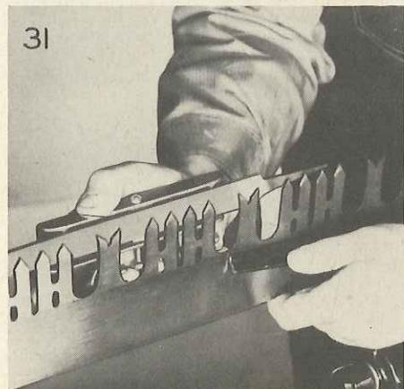
After filing job has been finished, fit file flat into saw tool, Fig. 31, and pass it lightly over saw on each side to remove burr or rough edge on the side of the saw caused by filing.


CIRCULAR SAWS
In home workshops, small mills and in manual training shops, circular saw blades used are generally 12 inches or less in diameter, and are one of three types, Cross Cut, Rip or Combination, Fig. 35.
Jointing and Shaking
Jointing, or making saw perfectly round, is usually the first operation. This is done by holding an abrasive stone in contact with revolving blade, Fig. 36. The saw is put on arbor reversed, so it runs backward. Table is lowered or saw raised slowly until teeth touch the stone. Proceed carefully. Stop saw often to examine the blade. Jointing is complete as soon as every tooth has been touched by stone. Rakers of combination saws are jointed 1/64-inch lower than cutting teeth, by using a file or stone over a wood block, Fig. 37.
After jointing, put saw in a clamp, Fig. 33, and file teeth as near to original shape as possible. There are two general types of teeth, chisel point for ripping, and needle or spur point for cut-off and crosscut saws. The combination blade combines features of both rip and cut-off saws. The most popular type of combination saw is hollow ground, tapering from rim to center so that it can be run without set.
Setting Circular Saws
Setting, or bending tips of the saw teeth, alternately right and left, when required, is done after jointing and shaping operations, but before sharpening. Setting can be done with a hand set, or with a setting stake or anvil, Fig. 41.
A hand set is best adjusted by placing it over a tooth while blade is on saw arbor. Keep in mind that a power-driven saw does not require as much set as a hand saw. In cases where a blade is to be used almost entirely in soft wood, depth of the set may be slightly greater, that is, more of the tooth should be bent, but the width across points should never be as great as that shown in B Fig. 39, where a "valley" appears between two adja-


• 14 •
cent teeth. Discrepancies of this kind may be remedied by resetting blade with tool properly adjusted. In setting a crosscut saw, coarseness of set should not exceed that shown in detail A, Fig. 38. If saw is to be used mostly for hardwood, you can use even less set. After adjusting saw set, bend each allernale tooth in same direction, so that two adjacent teeth will be set toward opposite sides of saw blade. Be sure to reset teeth on which trial was made, so they will be in line with the rest. After every second tooth has been reset on one side, reverse set or blade, and repeat the operation, finishing the remaining teeth. Be sure adjustment of tool does not shift while setting, and that it does not slip when pressure is applied. In setting a combination blade, omit setting of raker teeth.
Sharpening Circular Saws
After setting comes sharpening. Place saw in a clamp as in Fig. 33. Don't try to hold a saw in ordinary vise. Use a good file. You'll need an 8-inch mill file with one round edge and a 6 or 7-inch slim taper file. In sharpening a rip saw blade, use a round edge mill file and file straight across, with file held at right angles to blade. Take care to bring each tooth to a point and keep its original form. File every other tooth, then turn blade around and file from opposite side. This helps equalize filing strains.
In sharpening crosscut teeth file them as nearly as possible the same as when the saw was new. The file must be held at an angle with blade both vertically and horizontally, so that teeth will be shaped at an angle as shown in detail A and B, Fig. 38. Note that angle of cutting edge in B is slightly greater than in A. Run file down into gullet to keep original form of teeth, and prevent formation of a shoulder in subsequent filings.
Gumming
Gumming is deepening of the gullets between ripping teeth. After the first two or three filings of a ripping blade, gullets should be filed with a round file of suitable diameter, Fig. 34. Make strokes straight across. Two or three strokes in each gullet should be sufficient. Cutting teeth of combination and crosscut blades are more or less automatically gummed by each filing.
Dressing Teeth
After filing, teeth need dressing with a siliconcarbide stone to bring cutting points in line. Place blade on a saw arbor to run the right way. Lay stone on edge against rip guide with fine side next to saw. Do not allow the stone to strike upcoming teeth, but only those going down. Leave guide free so it may be moved easily. Start motor and bring stone against teeth lightly, allowing it to touch only sides of saw points. Keep stone flat. Repeat operation on other side of the blade. Don't take off too much, just enough to even points and bring them in line. If rip guide assembly will not permit this procedure, lay the saw blade on a flat surface and rub teeth lightly with fine side of stone.
Fig. 40 shows a good way to store saws.
SHARPENING DADO HEADS
A dado head, sometimes called a dado saw, is a device for cutting grooves. Complete head consists of two solid outside saws and a number of chipper blades, Fig. 42.


A small dado head may be sharpened by using same method described for saw blade.
A small dado head may be jointed and filed by using practically the same method as for a saw blade. To joint the head, use strips clamped to saw table as before, and assemble all separate cutters on arbor, so they run backward. Use coarse side of stone in jointing. If this is carefully done, no harm will result to stone. Next, remove head and carefully file outside cutters. Note shape of teeth and take care not to alter their shape. When filing is complete, give each raker tooth an additional stroke with a file. Assemble all inside chippers on arbor, and joint them again very lightly, again with dado running backward. Then remove and file top of each tooth straight across, just back of cutting edge, to remove rounded portion caused by jointing.

Saw swage and tooth gauge. Teeth of saw are filed to fit opening in gauge.
CORDWOOD SAWS
Cordwood saws are used for cross cuts only; that is, across the grain. In reconditioning a cordwood saw, a section of which is shown in Fig. 43, the first step is to see if it is out of round. Turn saw by hand and keep an eye on the teeth. If the saw is much out of true, "jumping" of teeth can readily be detected as saw turns slowly. To even the teeth or "joint" the saw, fasten a large flat file, or silicon-carbide stone, to a board and improvise a jig to hold it squarely across points of saw while it is rotated backward by hand. This will make all points of saw teeth the same distance from center.
Gumming Cordwood Saws
A cordwood saw should be gummed or have spaces between teeth called "gullets," ground out to a uniform depth and shape occasionally, to keep it in good condition. Fig. 44 shows sections of several saws that are badly in need of gumming. Gumming is done with a round file or a power grinder fitted with a round-face wheel about 6 inches in diameter, of suitable thickness. A circle which indicates depth of gumming is made by holding a piece of chalk against blade while it is turned by hand . Provide a suitable4 support or stand for saw so it may be fed into grinder with accuracy and ease. Press saw against grinder lightly. Grind a bit in one gullet then go to the next. Avoid heating. Make all gullets round at corners—AVOID SQUARE CORNERS.
Setting and Filing
After gumming comes setting of teeth. Setting consists of slightly bending teeth ALTER - NATELY , first one to the right, then one to the left. Use a set of proper size for blade at hand; adjust it to bend teeth just enough to provide clearance of blade in cut, to prevent side of blade from rubbing. Do not allow set to extend into a tooth MORE THAN ONE-THIRD OF THE HEIGHT OF TOOTH . In other words, bend only outer third of tooth. A homemade gauge, which will come in handy in checking set of a saw, is shown in Fig. 45. Screws A, B, C, D remain stationary and screw E is adjusted so it just touches tip of a properly-set tooth. Adjust screw E to get wanted amount of set.
Parts of a cordwood saw tooth to be filed are shown in Fig. 43. Leave saw on arbor to file if possible; if not, provide a stand that holds blade securely. The drawing also indicates shape to which teeth should be filed. Using a flat mill file, file both front and back of each alternate tooth until a complete circuit of blade is made. Then remove saw from arbor or clamp, reverse it and sharpen unfiled teeth.
SPRING-SET CIRCULAR CROSSCUT SAWS
Follow same sharpening procedure as described for cordwood saws.
CIRCULAR SPRING-SET RIPSAW
Follow same sharpening procedure as in cordwood saws. Joint and set blade the same as with a crosscut saw. In gumming be sure to maintain original shape of gullets. In filing, the teeth are filed straight across , that is, at right angles to blade.

SHARPENING A BANDSAW: Jig for holding bandsaw blade while sharpening consists of two wooden discs bolled onto a board, one end of which is slotted for tension adjustment. Jig is fastened near wood vise so portion of blade will fit between wood blocks in vise which hold saw blade while sharpening. Joint blade by running mill file lightly over tons of teeth. Set in same manner described for hand-saw teeth, page 10,


hand down and left hand up to form two loops in the saw blade.
USING A SAW SWAGE
Swaging a saw tooth spreads it out at the tip so it cuts on both sides. A swaging tool and gauge are shown in Fig. 47. It is essential that you use a swaging tool designed especially for the blade at hand. The first step is to file the teeth at right angles to the blade and to fit the tooth gauge.
Fig. 46 shows a cutaway view of a swaging tool indicating how dies fit over the teeth. There are
In filing bandsaw blade use slim-taper file. Hold file horizontal. File straight across at right angle to blade, raising file on back stroke. Try to keep saw teeth the same shape as when new.

53 54
two dies, one with convex face and the other with a flat face. Apply oil to the filed tooth, set swage with convex die in place on tooth and tap with a light hammer. Do not strike heavy blows. Next, use die with flat face, to square up point of tooth.
Be careful not to drive some points of saw teeth lower than others. Swage set saws are commonly run without any further set.

WOOD-WORKING POWER TOOLS
SHARPENING JOINTER KNIVES
Honing
It is possible to keep jointer knives in satisfactory cutting condition for some time by honing alone. The drawing at the top of the page, Fig. 1, shows the operation. A fine abrasive stone is partly covered with paper so that it will not damage the surface of the jointer table. The stone is placed on the front table, and is stroked back and forth the full length of the knife. Each knife should be treated in turn, it being advisable to give each of the knives the same number of strokes.
Best results are obtained if the head is securely fixed so that it cannot turn while the operation is being done. A simple method of doing this is to wedge the belt against the machine stand with a block of wood as shown. Or, you can use a Cclamp to fasten the belt to the machine frame. The front table should be carefully adjusted so that the stone presses slightly against the full surface of the bevel. A small abrasive stick or a piece of abrasive paper wrapped around a steel rule can be used to remove the slight burr turned over by the honing action.
Jointing
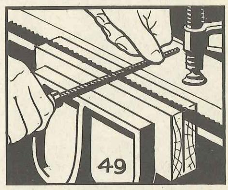
Preliminary to grinding or honing and often used as a sharpening technique in itself, jointing is done with the machine under power. In this case, the abrasive stone is placed on the rear table, as can be seen in Fig. 2. A stop block should be mounted on the front table of the machine, using a large clamp, to eliminate the slight tendency of the knives to kick the stone forward.
The rear table should be raised until the stone is entirely in the clear, and then gradually lowered until the stone takes a slight bite on the revolving head. The stone is moved across the table to joint the full length of the knives. No more metal than is absolutely required should be removed. The jointer should be stopped immediately after the first light bite and each knife inspected. One or two light jointings of this kind serve very well to sharpen the knives, especially when combined with a thorough honing which should always follow jointing. When the secondary bevel becomes too long, it will be necessary to remove the knives from the machine for complete grinding in order to maintain a proper back clearance.
Grinding Knives
Most jointer knives are ground to a 36° bevel, as shown in Fig. 3, below, and this bevel should be retained in the grinding operation. To insure accurate grinding, the knife should be mounted in a suitable holding block. If the work is to be done on a grinder, the holding block will have a right angle saw cut in one edge to hold the knife, as shown in Fig. 5. The groove alone will usually hold the knife securely for the grinding operation. However, as a safety precaution, screws can be run into the block to clamp the knife tightly in the groove. The tool rest of the grinder should be tilted to give the required bevel, Fig. 4. A guide block should be clamped to the tool rest to insure grinding to a straight line. If the tool rest of the grinder at hand does not tilt, the work can be done by mounting the knife at the required
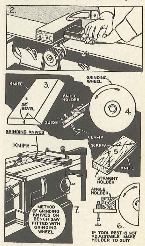
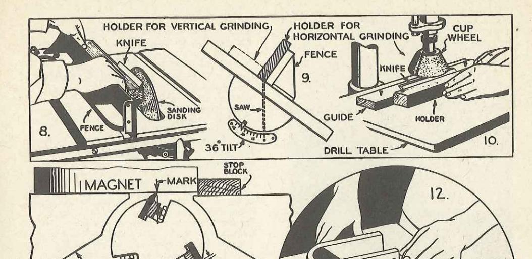
angle in a wood block, as shown in Fig. 6. In this case, the exact angle of the saw cut must be determined by making a full-size layout, since it will vary with the size of the grinding wheel and the point of contact. Make full size layout on paper, using a protractor to establish the correct angles. In sawing holding block be careful to maintain these same angles. This same operation is more satisfactorily done by mounting a grinding wheel on the bench saw arbor, as in Fig. 7. It can be seen that the miter gauge furnishes an accurate guide, while the raising and lowering mechanism of the saw provides for slight adjustment and feed. When grinding is to be done on either a vertical or horizontal grinding surface, the knife bevel must be secured by mounting the knife at the proper 36° angle in the holding block. Fig. 9, shows how the block is grooved for both turner of grinding.
Grinding on the drill press with a cup or recessed wheel, as shown in Fig. 10, has the advantage of perfect control over the feed. The proper setting for each cut is obtained by bringing the wheel lightly in contact with the knife edge, this being done with the wheel standing still. When the power is applied to the wheel, the cut will be found just about right, due to slight inequalities in the surface of the wheel. In this type of grinding, the levelness of the wheel in relation to the knife must be carefully checked by sighting by eyee, and readjusted slightly if required by tilting the drill press table. Fig. 8, shows grinding being done on the circular saw, using either a grinding wheel or a sanding plate with an aluminum-oxide dise attached
Great care should be used in any set-up for grinding knives in order to make the removal of actual metal as little as possible, and thereby simplify the job and increase the life of the jointer knives. Jointer knives are usually high speed steel and should be ground dry, air-cooling at frequent intervals to prevent burning. The abrasive wheel should be aluminum oxide, medium soft and about 60-grit. If the sanding plate is being used, the abrasive disc should be aluminum oxide, about 80-grit.
Resetting Knives
After grinding it is necessary to reset the knives in the cutterhead. This is an important operation and must be done carefully else an excellent job of sharpening will be wasted effort. One of the best methods makes use of a mag-
One of the best methods makes use of a magnet. To make the set-up, clamp a block of wood across the front table of the jointer to supply a stop for the end of the magnet. The block should be exactly parallel with the slots in the jointer head. Next, place the magnet in position on the rear table, and locate on the magnet the exact spot where the knife is at its highest cutting point. Make an arrow at this point, as in Fig. 11. Each knife is set to this mark, as shown in Fig. 12. Tighten the two end screws first and then recheck to determine if the knife is properly aligned. Knives should project about 1/16-inch from the cutting head. The end projection should be checked carefully since equal projection of all knives is essential for good work.
SHARPENING SHAPER CUTTERS
Get the cutters ready for sharpening by washing in benzine or gasoline to remove the accumulation of pitch which is usually present.
Touching up of cutters with curved bevel is done by whetting the flat side of the cutters on an oilstone, working against the sharp edge. Grinding, if required to remove nicks, should also be done on the flat side of the cutter, using a finegrit wheel. Working on the flat side of the cutters will bring them to a sharp edge without danger of spoiling their shapes.

SHARPENING TURNING CHISELS
Wood turning chisels are usually made from a select grade of high-carbon steel, with vanadium or other alloy added for toughness. They should be ground with a wheel of fine grit; the wheel being dry but the tool dipped frequently in water to prevent burning the metal. The grinding operation is conveniently done on the wood lathe at about 2400 R. P. M. with a 6 or 7-inch diameter wheel. Bevels of all chisels should be maintained at the approximate angles given in Fig. 17 at the bottom of this page. All bevels must be straight or very slightly convex. Hollow grinding must be avoided when grinding turning chisels since this type of grind destroys the fulcrum action of the bevel.
Always use safety goggles in grinding, to protect your eyes from flying grit.
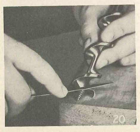
Sharpening the Gouge
The best method of sharpening a gouge with an outside bend is shown in top photo, Fig. 13. The gouge is rotated away from the operator. The bevel is visible at all times, making it easy to get a clean cut while maintaining the original bevel. The slight burr turned over on the inside of the chisel can be removed with the use of a tapered wooden spindle covered with No. 3 emery cloth, as shown in Fig. 14. Another method uses a round slip stone, as in Fig. 15. Care must be taken to keep the cutting arc true.

Sharpening the Skew
A precision method of grinding the skew chisel is shown in Fig. 16, where the chisel is locked at an angle in the slide rest tool post and then fed into the side of the grinding wheel. Both side faces are ground to permit cuts to both the right and left. Care should be used in making the setup to maintain the original bevel. Lacking the slide rest, the same operation can be done freehand, resting the chisel on the wood turning tool rest. Be sure all ground surfaces are flat, as hollow grinding makes it difficult to hold the tool in the correct position.
Sharpening Other Chisels
Other wood turning chisels present no great difficulties in sharpening. The point of the parting tool must come exactly at the center where the chisel is thickest. Grind the tool so that the sides are straight or slightly hollow ground. The spear point chisel is sharpened on the side of the grinding wheel, much the same as the skew chisel. The round nose chisel is rolled very much like the gouge. In all cases, touch-up sharpening by honing on a flat oilstone should come three or four times between grindings. Move the chisel back and forth over the surface of the stone, always working against the cutting edge.


• 20 •
METAL - CUTTING POWER TOOLS
METAL LATHE BITS
To get the best results from a metal lathe, the tool bit must have a keen, properly-shaped cutting edge. The shape to grind the bit depends on the class of work (roughing or finishing) and upon the metal being cut.
The angles to consider when grinding a cutting bit are four, namely: back rake, side rake, front clearance and side clearance as shown in Figs. 2, 3, 4 and 5. The front clearance angle allows the part of the tool directly under the cutting edge to clear the work while taking a chip. Too much clearance weakens the cutting edge, and the high pressure exerted downward on the tool bit demands the clearance be as small as possible and still allow the tool to cut properly. A tool with excessive clearance also has a tendency to chatter.
Figs. 3 to 10 inclusive show five forms of tool bits. The shapes are suitable for practically all lathe turning and cutting of 60-degree V-type threads.
Grinding Tool Bits
A good tool grinder is essential, preferably one that is motor driven, fitted with a medium (about 60) grit wheel.
(about ou) girt wheel. Three views of the process of grinding a right hand turning bit are shown in Fig. 11. The bit can be sharpened on either the side or the face of a grinding wheel, although the regular cutting face is used by most machinists, and is generally considered better grinding practice. In all toolbit grinding, whether on the face or side of the wheel, it's important to prevent burning of the tools. A cupful of water should be kept handy so the bit can be dipped frequently.
Some experience is required to get the knack of tool bit sharpening, but by comparing each side of the bit carefully with the angle given in the drawings and the table, Fig. 13, anyone handy with tools can readily become adept at this important part of lathe operation.
When grinding for special work, simply keep in mind the shapes and angles recommended for general turning, and apply these principles to the special tool being ground. There is no point in honing the edge of a tool used for heavy roughing cuts in steel. In turning steel, a fine edge lasts for only a few feet of cutting, then it rounds off to a more solid edge and remains in approximately this same condition until the tool breaks down.
For fine finishing cuts, the tool should be ground to shape and then honed with a reasonably fine stone. You can either fasten the bit in the lathe tool holder and work an oilstone against the cutting edge, or hold the bit in one hand and work it back and forth over the stone, sharpening against the cutting edge.
In most fine finishing operations the excellence of the finish depends directly upon the keenness of the edge of the tool. Tools for soft metals should be honed carefully to as fine an edge as possible—both the cutting action and the finished surface depend upon the edge of the tool.

Nothing is more essential for clean, ac-

Four angles to consider in sharpening tool bits are back rake, side rake, front clearance and side clearance.

Tool bit angles as designated for use in the tool holder.

Angles of the tool bit in relation to the work
TOOL BIT SHAPES
Standard tool forms shown in Figs. 6 to 10 inclusive, will be found suitable for mos lathe turning. In grinding for special work keep in mind shapes and angles recom


Round nose cutting tool suitable for roughing and general purpose turning.


Excellent R. H. tool for general turning and shouldering toward headstock; also facing Point should be rounded for finishing work


Excellent L. H. tool for general turning and shouldering toward tailstock; also facing, Point should be rounded for finishing work.


Heavy duty R. H. roughing tool. for taking deep cuts toward headstock.


R. H. 60° V-type threading tool for cutting toward headstock. Side clearance angle should be reversed for L. H. threading.

GRINDING TOP AND SIDE RAKE
Three views of the process of grinding a R. H. turning tool bit.
Whenever a lathe tool digs into the work and refuses to cut unless forced, check the clearance of the tool bit. Digging in occurs most often during facing and threading operations. For light turning it is better to allow just a little extra clearance. On heavy work, the clearance angle should be as small as can be used without hogging.

SPECIAL FORM-CUTTING TOOL. In using form tools with side faces such as shown in A and D, side rake is out of the question. Front rake, however, should be used except when turning brass. Tools wider than 1/2 inch should never be used on steel. Form cutting tools as wide as 1/2-inch can be used on brass, aluminum and similar metals.
Success in metal cutting depends not only on having a properly shaped and ground tool bit, but on the bit being set at the right angle to the center line of the work, and the correct choice of cutting speed. Too slow a speed not only wastes time, but leaves a rough finish on the surface of the metal—too high a speed burns the tool.
| FIG. 13 DAT | A FOR | THE M | ACHININ | G OF | VARIOUS M | ATERIALS |
|---|---|---|---|---|---|---|
| MATERIAL |
Front
Clearance |
Side
Clearance |
Back
Rake |
Side
Rake |
Cutting Speed
Feet Per Minute |
LUBRICANT |
| STEEL (MILD COLD ROLLED) | 8° | 8 ° | 161/2 HOLDER | 22 ° | 80 to 100 | DRY OR CUTTING OIL |
| STEEL (MEDIUM HARD) | 8 ° | 8 ° | 12° | 14° | 60 to 80 | CUTTING OIL |
| STEEL (TOUGH ALLOY) | 8 ° | 8° | 8 ° | 12° | 50 | CUTTING OIL |
| CAST IRON | 8° | 8° | 5° | 12° | 50 | DRY |
| STAINLESS STEEL | 8 ° | 10° | 161/2° | ł0° | 40 |
CUTTING OIL OR
SULPHURIZED MINERAL OIL |
| COPPER | 12° | 14° | 161/2° | 20 ° | 120 | DRY OR CUTTING OIL |
| BRASS | 8 ° | 8 ° | 0° | 0° | 200 to 300 | DRY OR PARAFFIN OIL |
| BRONZE | 8° . | 8° | 0° | 2° | 80 to 120 | DRY OR PARAFFIN OIL |
| HARD BRONZES | 8° | 12° | 10° | 2° | 30 to 80 | DRY OR PARAFFIN OIL |
| ALUMINUM | 10° | 8° | 35° | 15° | 200 to 500 | DRY OR KEROSENE |
| MONEL & NICKEL | 10° | 13° | 8 ° | 14° | 100 to 120 | SULPHURIZED MINERAL OIL |
| MOLDED PLASTICS | 12° | 8 ° | 0° | 0° | 100 to 120 |
TURN DRY
THREAD WITH CUTTING OIL |
| CAST PLASTICS | 14° | 10° | 0° to -5° | 0° | 150 to 200 |
TURN DRY
THREAD WITH CUTTING OIL |
| FORMICA & MICARTA | 15° | 10° | 161/2° | 10° | 200 | DRY |
| FIBER | 15° | 12° | 0° | 0° | 80 | DRY |
| HARD RUBBER | 20° | 15° | 0° to -5° | 0° | 200 | DRY OR COOLANT |
Above angles are recommended by competent authorities. All angles are true angles, measured from horizontal and vertical planes. Speeds are correct for standard high-speed tool bits. Special alloy bits permit a somewhat higher cutting speed.
RESULTS OF DRILLING WITH IMPROPERLY SHARPENED DRILLS
METAL CUTTING TOOLS
SHARPENING TWIST DRILLS
I wo rules are especially important when grinding twist drills. First, the lip clearance angle, shown in Fig. 9, should be between 12 and 15 degrees. Second, the two cutting edges must be of equal length and angle. The unsatisfactory results of disregarding these two rules are shown by the shaded portions of Fig. 6. At the left the lips are of unequal angle and unequal length. The drill point actually travels around the center of the hole, making a hole that is actually larger than the diameter of the drill. The center drawing shows lips of unequal angle. The right lip is doing all the work. At the right the lips are of equal angle but unequal length, causing excessive wear on the right lip.
The point angle of a properly ground drill is 118 degrees or 59 degrees on each side of the centerline for general drilling of steel, iron and brass—larger angles are frequently used in production work and on softer metals. The angle is measured directly over the cutting lip, and is checked by means of a drill point gauge, two types of which are shown in Figs. 2 and 4.
Grinding a drill consists of removing a small amount of metal from the point while retaining the point angle and lip clearance. Expert mechanics can do this quite accurately by eye, but the average craftsman will do best by using a guide board fitted over the tool rest of the grinder, see Fig. 10. The guide lines at 59 degrees establish the point angle, while the 47 degree lines mark the position for a lip clearance of 12 degrees. The drill is placed against the side of the grinding wheel, Fig. 11, with the cutting lip in contact with the wheel. From this position the drill is swung to the second position, at the same time giving it a twist of about one-sixth of a full turn. One or two light cuts on each lip will usually bring up a sharp edge.
Sharpening on the face of a grinding wheel is shown in Figs. 1, 15 and 16. The drill is touched to the wheel at the proper angle, and is then pushed upward. A slight rotation is all that is needed, since the upstroke provides most of the required clearance.
The web of a drill, Figs. 12, 13 and 14, becomes thicker as it approaches the shank, Fig. 5. On large drills, this web thickness becomes excessive as the drill wears down, necessitating very heavy pressure to force it through the work. When this condition arises, the web should be thinned. This is preferably done on a round edge grinding wheel. Metal is removed from the immediate point only. The cutting lips should be kept straight, even if it is necessary to grind completely out to the margin after thinning the web. A second method of web thinning is done on the backs of the cutting lips, using a square edge wheel, Fig. 15.
Drilling Soft Metals
When drilling brass, aluminum, lead and other soft metals which cause the tool to "hog in," reduce the rake angle of the cutting edge as shown in Fig. 5. This reduced rake angle is also desirable when drilling very hard materials.


SHARPENING COLD CHISELS
To get the most out of your cold chisels cut only metal softer than the chisel. Cold chisels were not made to cut such objects as hacksaw blades and drill rod. Always use a heavy hammer. A light hammer has a tendency to form burrs on the head of a chisel, and doesn't transfer the force of a blow to the cutting edge of the chisel as well as a heavy hammer.
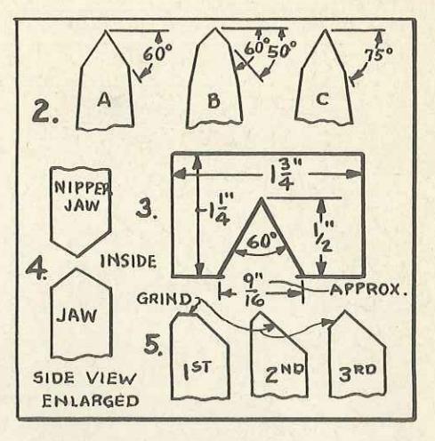
Bevels on opposite sides of chisel should be alike. The angle to grind a cold chisel, Fig. 2, depends on the job at hand. For average use, 60 degrees is best. A template, Fig. 3, will be helpful in judging the angle. This is simply a piece of sheet metal notched as shown. A chisel, ground to fit the notch, is properly beveled for average work. Grind against the cutting edge, Fig. 1, and dip the chisel in water often to keep from drawing the temper.
On a job of making deep cuts in soft metal or cutting thin sheet iron, a chisel may be ground to a longer, thinner point, Fig. 2, right hand detail. On extra-heavy work a chisel ground with a double bevel, center detail, will give good results.
Finishing touches consist of removing any wire edge that may be present by using an oilstone, rounding the corners slightly, and grinding off burrs.
SHARPENING CARPENTERS' NIPPERS
The cutting edge on carpenters' nippers, like all cutting edges, should be renewed occasionally. Fig. 4, shows side view of properly sharpened nippers.
It edges are nicked, grind back to the depth of the nicks, holding the face of each jaw against the side of the abrasive wheel at right angle, Fig. 6. First, grind to flatten edge as indicated in left hand detail, Fig. 5. Second, turn nippers and grind at the approximate angle shown in center detail. Third, grind as shown in right hand detail.
SHARPENING TIN SNIPS
The cutting edge on tin snips, either duck bill or regular snips, can be quickly renewed with a grinder, as in Fig. 7, or a stone, Fig. 8. Be sure to retain original bevel and grind slowly so temper won't be drawn. Remove wire burrs by touching up the inside surface with a stone.
SHARPENING WIRE-CUTTING PLIERS
After prolonged use, cutters on pliers are generally dulled and will work better if renewed. You can use a thin abrasive stone or abrasive


In sharpening a knife on an oilstone, hold knife at angle of about 30° as shown below; work against cutting edge.

stick, the exact size to use depending upon the type of pliers. A small file may be used on pliers where the cutters are not too highly tempered.
CUTLERY SHARPENING POCKET KNIVES
In sharpening a pocket knife you will need a silicon carbide or aluminum oxide stone, with medium grit on one side and fine grit on the other.
In examining the blade of an ordinary pocket knife, you'll find that the cutting bevel extends back only a short distance. This bevel should be maintained during the sharpening operation. Grasp the knife, hold the blade on the stone as shown in Fig. 4, so the bevel edge will rest at an angle of about 30 degrees, Fig. 5. Rub the blade back and forth in long, straight strokes across the surface, always sharpening against the sharp edge. You could sharpen the blade by using a circular motion, but straight strokes will sharpen it quicker and give it a truer cutting edge. Proceed slowly until a sense of "feel" is developed. Whet first on one side, then on the other.
Sharpen on the coarse side of the stone until a burr or "wire edge," appears. Then, turn the stone over and whet on the fine side. Continue to work against the sharp edge, first on one side of the blade, then on the other. The edge can be smoothed still more by stropping on an old razor strop or a piece of leather belting.

To sharpen heavy butcher knife, grind diagonally away from the handle. Always maintain original cutting bevel of blade.

When putting on finishing touches with a steel, start each stroke at the heel of the blade. Use light pressure only.

Sweep down diagonally covering the full length of blade with each stroke. Work first on one side, then on the other.

SHARPENING KITCHEN AND BUTCHER KNIVES
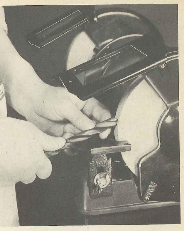
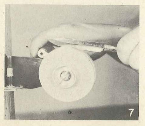
A thin-blade paring or bread knife may be sharpened satisfactorily on an oilstone, using the procedure just described for pocket knives. You can also sharpen such a knife on a small handoperated grinder as shown in Figs. 6 or 7. Thinblade knives should not be sharpened on a highspeed power grinder.
A power grinder can be used to good advantage in sharpening heavy butcher knives. First, lay the blade flat on the tool rest with the edge square against the abrasive wheel and grind away sufficient steel to remove any nicks that may be present.
To bevel the blade, grind loward the culting edge, diagonally away from the handle of the knife, Fig. 1, page 27. Grind both sides equally and continue until a burr or wire edge is formed. Finish the sharpening on an oilstone, always working toward the cutting edge, or by using a steel, Figs. 2 and 3. In using a steel, hold it in your left hand, the knife in your right hand with the back of the blade lifted slightly. Start each stroke at the heel and sweep down diagonally covering the full length of the edge with each stroke. Work first on one side of the steel, then on the other, always using light pressure.
SCISSORS
Dull scissors or household shears, may be sharpened on a household sharpener as in Fig. 8, or on an oilstone, as shown in Fig. 12. In using a household sharpener a disc mounted on the side of the wheel serves as a guide to help you hold the scissors at the proper angle. It's best not to sharpen scissors and shears on a high-speed power grinder—especially a power grinder fitted with a medium or coarse-grained wheel.
In sharpening on an oilstone, apply the blade so the bevel lies accurately upon the face of the stone with the blade crossing it at right angles. Draw the blade across the stone from the heel to the point, using one finger to guide and hold the scissors at the correct angle. Start each stroke at the heel and do not allow the blade to rock back and forth.
SHARPENING STRAIGHT RAZOR
Keeping a keen edge on a razor requires the use of both a hone and a razor strop. The edge of a razor blade consists of minute projections. Shaving bends the tiny projections and the blade will soon pull unless the projections are straightened or removed. Stropping a blade straightens the projections, and keeps a razor in good shape for shaving until so many of the projections are broken honing is required to form a new cutting edge.
Honing
In honing, lay the razor flat on the hone diagonally across the surface, Fig. 9. Do not raise the back of the blade as the thick back takes care of the bevel. Draw the blade from right to left, as it moves over the full length of the hone against the edge —not away from the edge. Turn the razor over, rolling it on the back, and draw from left to right against the edge, Fig. 10. Hone lightly. Very little pressure is needed. The edge of a razor is extremely thin and sensitive, and heavy pressure will take off instead of put on a keen edge. The number of strokes necessary depends on the condition of your razor. Ordinarily six to ten strokes is sufficient. Great care should be taken not to overhone a razor, as it produces a fine wiry edge which will curl over when coming in contact with the beard and will not give a clean, smooth shave.
Be sure to keep the hone in a dust-proof container while not in use.

Stropping
In stropping, hold the strop tight—sagging would cause the edge of the razor to be rounded —and lay the blade flat on the strop. Draw the razor the length of the strop diagonally from heel to point, away from the culling edge—not against it, as in honing. See Fig. 11. At the end of each stroke, roll the razor on its back to turn it over; then repeat the operation to strop the other side
The last couple of strokes should turn the edge so it will be away from the skin, while the razor is in use. Stropping provides the friction a razor blade needs. For a smooth shave without pull or irritation, strop before each shave. Dry blade after each shave and strop again to make sure all moisture has been removed.
It's a good idea to spend a few minutes occasionally putting the strop in condition. Remove dust, dirt and grease by washing with soap and water. Cuts in the strop may be repaired by gluing loose portions back in place, making certain that there are no harmful cracks or ridges which will interfere with the proper stropping of your razor.
SHARPENING SAFETY RAZOR BLADES
Safety razor blades of the double-edge type can be sharpened quite effectively by using a hone as shown in Fig. 13. The blade is worked back and forth across the hone lengthwise a few times, as indicated by the arrows, then turned over and sharpened on the opposite side. Be sure to keep your hone clean, and the surface free from dust and glaze.
Another method of reconditioning a safetyrazor blade is to rub it on the inside of a drinking glass having a smooth, even surface. The surface of the glass smooths out the minute projections on a safety razor blade like a strop does a straight razor and enables you to get more use from your blades.
SHARPENING HAIR CLIPPERS
Valve grinding compound as used by auto mechanics, can be used to good advantage in sharpening hair clippers. Spread a small quantity of the compound on a piece of smooth flat glass, take the clippers apart and work the cutting edges back and forth several times across the compound. Before reassembling and testing the clippers, wash all parts in gasoline to remove the grinding compound, because if compound is left in clippers the abrasive action of this material will soon ruin hair cutting action.


In honing a razor, lay blade flat on the hone. The thick back takes care of the bevel.

Let the razor roll on the back at the ends of the strokes. Always work against the cutting edge, as indicated by the arrows.

In stropping work away from the cutting edge instead of against it.


Using scythe stone to maintain cutting edge. Lower end of snath rests on the ground. Blade drops under arm as sharpening proceeds.

Holding scythe in this position while grinding causes formation of fine "teeth" which point toward tip of blade.

Sharpening should be done on down strokes, alternately first on one side of blade, then on other, moving forward slightly with each stroke.
A good file is the only sharpening equipment needed to maintain a keen edge on an ordinary garden hoe.

Shears used exclusively on light twigs may be ground to a long bevel; on heavy stock it's advisable to keep bevel short.

A spade, too, works better if ground occasionally to renew the cutting edge.
GARDEN TOOLS
SCYTHES AND GRASS HOOKS
To sharpen a scythe or grass hook you'll need a grindstone, or a grinder fitted with a mediumgrained wheel from which the guards can be removed so the blade can be ground as in Fig. 2. The blade is held with the handle end down which causes the grinder to make a serrated edge with the serrations or "teeth" pointing toward the tip of the blade. Proceed slowly until you determine the angle the blade must be held to maintain its original bevel, then hold the blade at this angle consistently during the sharpening job. Grind on both sides equally, making the cutting edge in the center of the blade. Be sure to keep blade moving lengthwise so it won't be in one place long enough to remove temper.
Whetting
Removal of wire edge formed by grinding isn't necessary, it adds to cutting efficiency of these tools
It's well to have a stone, however, for maintaining the edge while on the job. Figs. 1 and 3 show how a scythe may be held while whetting, the lower end of the snath being placed on the ground. Strokes should be made alternately first on one side then on the other, moving forward slightly with each stroke. Sharpening is done on the down stroke, with the stone working away from the cutting edge.
SHARPENING HEDGE SHEARS
Separate blades as far as possible and grind cutting edge at an angle suitable for intended purpose. For light twigs and grass a comparatively long thin bevel works best; while on heavy stock, it's advisable to keep the bevel short. The sharpening job is completed by using an oilstone on the beveled surface to bring it to a keen cutting edge, and to touch up the side opposite the bevel to remove the wire edge.
Check to see if the cutting edge comes together when the blades are closed. If not, slight springing of the blades may be necessary.
SHARPENING PRUNING AND LOPPING SHEARS
When sharpening pruning or lopping shears, other than touching up the edges with an oilstone, the bars should be taken apart.
A round-faced wheel such as is used in saw gumming is needed in sharpening the heavy cutting bar, as shown in Fig. 7. Remove nicks by holding blade flat on tool rest. Then, hold the bar at an angle so the original bevel will be maintained. The wire edge which forms should be removed by honing. If you don't happen to have a round-faced wheel, you can do a fairly good job by grinding on the edge of a square wheel
Fig. 8 shows the sharpening of the cutting blade. The blade is moved back and forth to produce a rounded surface—holding it in one position to form a long bevel would make the edge too thin.
In sharpening snap-cut type of pruning shears touching up cutting blade with an oilstone is all that is usually required—hone carefully against cutting edge. If cutting blade is badly nicked, grind carefully toward the cutting edge, removing a minimum amount of metal and carefully

ABOVE: Sharpening cutter bar of pruning shears on round-face wheel. BELOW: Cutting blade is moved back and forth on square-edge wheel to produce a rounded surface.

maintaining the original bevel. Finish the job by honing on a fine oilstone.
SHARPENING GARDEN HOES
The only sharpening equipment needed to keep a keen edge on a garden hoe is a good file. When removing deep nicks and bringing the edge to the proper bevel, the hoe should be placed in a vise, Fig. 4. Best results can be obtained by working the file against the cutting edge. While using a hoe, it's a good idea to carry a file right along so you can touch up the edge frequently.

A wheel dresser should be used regularly on grinding wheels to remove glaze and bring wheels back to round.
CARE OF SHARP-ENING EQUIPMENT
GRINDING WHEELS
To get the most out of grinding wheels they should be dressed regularly to remove the glaze and to bring them back to round. Fig. 1, shows how the job is done with a wheel dresser which can be obtained at small cost. In use, dresser is held on tool rest firmly against grinding wheel and is moved back and forth across the surface. Do not remove more of wheel than actually necessary.
OILSTONES
Oilstones, like grinding wheels, must have care. One of the most important things to remember is to wipe off dirty oil each time the stone is used. Dried oil, glaze, etc., can usually be removed with gasoline. Small irregularities can often be removed by working a stone back and forth over a piece of emery cloth, fastened securely at the edges, Fig. 2. If there are large depressions or hollowed out places in the stone, one of the best ways to restore an even surface is on the side of a grindstone.
Or, you can use some aluminum oxide or silicon-carbide grit a little coarser than the stone, in a lapping operation. Mix the grit with water to form a paste. Pour the paste on a piece of flat metal, preferably cast iron, and work the stone with the worn side down, back and forth_over the grit, using a circular motion. Look at the stone frequently to check progress, being sure to stop as soon as the surface is smooth and flat. Wash off loose grit, let the stone dry and it should be as good as new.
FILES
Always use sufficient pressure to keep file cutting. Teeth will be dulled quickly if allowed to slide over work. Files should be kept clean of filings or metal chips. Tapping handle end on bench every few strokes will help loosen filings. the balance should be removed with a file brush.
Don't let files get wet, or store them in a damp place. And don't put files in a drawer or box

Working oilstone back and forth over emery cloth to smooth surface.
A simple bracket such as this, provides a good place to keep files when not in use. Your files will stay sharp longer.

Grinding wheels and grindstones must be mounted properly to get the most out of them, and it's safer too.
with other tools. Fig. 3, shows a simple and convenient tool panel bracket for files.
WHEEL MOUNTING
In mounting a grinding wheel check to see it is a good snug fit on the spindle, and that the cupped washers—never use flat washers—are turned as shown in Fig. 5. Discs of cardboard or blotting paper should be used between the washers and wheel to serve as shock absorbers. Always use goggles when using a grinder not fitted with guards.
Fig. 4 shows how caulking compound may be used to cushion a grindstone on the supporting shafts.

 Instruction Guides")


 Loading...