

INDEX
| BALLS | 3, 25 |
| BOWLS | 3, 14 |
| BOXES | 12 |
| BUEFING | 27 |
| CARPIOLE LEG | 17 |
| CENTEDING | 4 20 |
| CLUB FOOT | 17 |
| E 12 | |
| CTLINDERS | 3, 14 |
| DRILLING | . 23 |
| DUPLICATE TURNINGS | 8 |
| FACEPLATE TURNING | 10-14 |
| Mounting Work — Position of | |
| Tool Rest—Cutting to Cylinder | |
| -Various Cuts-Deep Recesses | |
| -Turned Boxes-Plug Chuck- | |
| ing-Rechucking a Bowl-Pic- | |
| ture Frames — Turned Balls — | |
| Segment Turning | - |
| FINISHING | 24 |
| FLUTING AND REEDING | 18 |
| FRENCH POLISHING | 29 |
| GRINDING | 26, 30 |
| INLAY TURNING | 15 |
| LARGE WORK | 14 |
| LONG TURNINGS | 9 |
| METAL SPINNING | 28 |
| METAL TURNING | 20-22 |
| Equipment-Marking Centers- | |
| Checking Centers — Mounting | |
| Work - Tool Bits and Cuts - | |
| Rake and Clearance—Position | |
|
Rake and Clearance—Position
of Tool—Turning a Shoulder— |
|
|
Rake and Clearance—Position
of Tool—Turning a Shoulder— Taper Turning |
|
|
Rake and Clearance—Position
of Tool—Turning a Shoulder— Taper Turning OVAL TURNINGS |
16 |
|
Rake and Clearance—Position
of Tool—Turning a Shoulder— Taper Turning OVAL TURNINGS PICTURE FRAMES |
16
13 |
|
Rake and Clearance—Position
of Tool—Turning a Shoulder— Taper Turning OVAL TURNINGS PICTURE FRAMES PLASTICS |
16
13 25, 27 |
|
Rake and Clearance—Position
of Tool—Turning a Shoulder— Taper Turning OVAL TURNINGS PICTURE FRAMES PLASTICS |
16
13 25, 27 12 |
|
Rake and Clearance—Position
of Tool—Turning a Shoulder— Taper Turning OVAL TURNINGS PICTURE FRAMES PLASTICS PLUG CHUCKING POST BLOCKING |
16
13 25, 27 12 15 |
|
Rake and Clearance—Position
of Tool—Turning a Shoulder— Taper Turning OVAL TURNINGS PICTURE FRAMES PLASTICS PLUG CHUCKING POST BLOCKING PEDILCED SOLIARES |
16
13 25, 27 12 15 15 |
|
Rake and Clearance—Position
of Tool—Turning a Shoulder— Taper Turning OVAL TURNINGS PICTURE FRAMES PLASTICS PLUG CHUCKING POST BLOCKING REDUCED SQUARES SANDING |
16
13 25, 27 12 15 15 26, 27 |
|
Rake and Clearance—Position
of Tool—Turning a Shoulder— Taper Turning OVAL TURNINGS PICTURE FRAMES PLASTICS PLUG CHUCKING POST BLOCKING REDUCED SQUARES SANDING |
16
13 25, 27 12 15 15 26, 27 14 |
|
Rake and Clearance—Position
of Tool—Turning a Shoulder— Taper Turning OVAL TURNINGS PICTURE FRAMES PLASTICS PLUG CHUCKING POST BLOCKING REDUCED SQUARES SANDING SEGMENT TURNINGS |
16
13 25, 27 12 15 15 26, 27 14 30 |
|
Rake and Clearance—Position
of Tool—Turning a Shoulder— Taper Turning OVAL TURNINGS PICTURE FRAMES PLASTICS PLUG CHUCKING POST BLOCKING REDUCED SQUARES SANDING SEGMENT TURNINGS SHARPENING CHISELS |
16
13 25, 27 12 15 15 26, 27 14 30 5 8 |
|
Rake and Clearance—Position
of Tool—Turning a Shoulder— Taper Turning OVAL TURNINGS PICTURE FRAMES PLASTICS PLUG CHUCKING POST BLOCKING REDUCED SQUARES SANDING SEGMENT TURNINGS SHARPENING CHISELS SIZING CUTS |
16
13 25, 27 12 15 15 26, 27 14 30 5, 8 |
|
Rake and Clearance—Position
of Tool—Turning a Shoulder— Taper Turning OVAL TURNINGS PICTURE FRAMES PLASTICS PLUG CHUCKING POST BLOCKING REDUCED SQUARES SANDING SEGMENT TURNINGS SHARPENING CHISELS SIZING CUTS SLENDER TURNINGS |
16
13 25, 27 12 15 15 26, 27 14 30 5, 8 9 |
|
Rake and Clearance—Position
of Tool—Turning a Shoulder— Taper Turning OVAL TURNINGS PICTURE FRAMES PLASTICS PLUG CHUCKING POST BLOCKING REDUCED SQUARES SANDING SEGMENT TURNINGS SHARPENING CHISELS SIZING CUTS SLENDER TURNINGS SPINDLES (How To Turn) |
16
13 25, 27 12 15 26, 27 14 30 5, 8 9 5-9 |
|
Rake and Clearance—Position
of Tool—Turning a Shoulder— Taper Turning OVAL TURNINGS PICTURE FRAMES PLASTICS |
16
13 25, 27 12 15 26, 27 14 30 5, 8 9 5-9 |
|
Rake and Clearance—Position
of Tool—Turning a Shoulder— Taper Turning OVAL TURNINGS PICTURE FRAMES PLASTICS |
16
13 25, 27 12 15 26, 27 14 30 5, 8 9 5-9 |
|
Rake and Clearance—Position
of Tool—Turning a Shoulder— Taper Turning OVAL TURNINGS PICTURE FRAMES PLASTICS |
16
13 25, 27 12 15 26, 27 14 30 5, 8 9 5-9 |
|
Rake and Clearance—Position
of Tool—Turning a Shoulder— Taper Turning OVAL TURNINGS PICTURE FRAMES PLASTICS |
16
13 25, 27 12 15 26, 27 14 30 5, 8 9 5-9 |
|
Rake and Clearance—Position
of Tool—Turning a Shoulder— Taper Turning OVAL TURNINGS PICTURE FRAMES PLASTICS |
16
13 25, 27 12 15 26, 27 14 30 5, 8 9 5-9 |
|
Rake and Clearance—Position
of Tool—Turning a Shoulder— Taper Turning OVAL TURNINGS PICTURE FRAMES PLASTICS |
16
13 25, 27 12 15 26, 27 14 30 5, 8 9 5-9 |
|
Rake and Clearance—Position
of Tool—Turning a Shoulder— Taper Turning OVAL TURNINGS PICTURE FRAMES PLASTICS |
16
13 25, 27 12 15 26, 27 14 30 5, 8 9 5-9 |
|
Rake and Clearance—Position
of Tool—Turning a Shoulder— Taper Turning OVAL TURNINGS PICTURE FRAMES PLASTICS |
16
13 25, 27 12 15 26, 27 14 30 5, 8 9 5-9 5-9 |
|
Rake and Clearance—Position
of Tool—Turning a Shoulder— Taper Turning OVAL TURNINGS PICTURE FRAMES PLASTICS |
16
13 25, 27 12 15 26, 27 14 30 5, 8 9 5-9 5-9 |
|
Rake and Clearance—Position
of Tool—Turning a Shoulder— Taper Turning OVAL TURNINGS PICTURE FRAMES PLASTICS |
16
13 25, 27 12 15 26, 27 14 30 5, 8 9 5-9 5-9 18 9 22 24 |
|
Rake and Clearance—Position
of Tool—Turning a Shoulder— Taper Turning OVAL TURNINGS PICTURE FRAMES PLASTICS |
16
13 25, 27 12 15 26, 27 14 30 5, 8 9 5-9 5-9 18 9 22 24 19 |
|
Rake and Clearance—Position
of Tool—Turning a Shoulder— Taper Turning OVAL TURNINGS PICTURE FRAMES PLASTICS PLUG CHUCKING POST BLOCKING REDUCED SQUARES SANDING SEGMENT TURNINGS SHARPENING CHISELS SIZING CUTS SLENDER TURNINGS SPINDLES (How To Turn) Roughing — Cutting to Size— Smoothing a Cylinder—How Skew Cuts—Shoulders—Vee Grooves — Beads — Coves — Duplicate Turnings — Steady Rest—Back Stick—End Turning —Long Work—Lathe Salety SPLIT TURNINGS STEADY REST TAPER TURNING (Metal) TAPS AND DIES TWIST TURNINGS |
16
13 25, 27 12 15 26, 27 14 30 5, 8 9 5-9 5-9 18 9 22 24 19 20 |
|
Rake and Clearance—Position
of Tool—Turning a Shoulder— Taper Turning OVAL TURNINGS PICTURE FRAMES PLASTICS PLUG CHUCKING POST BLOCKING REDUCED SQUARES SANDING SEGMENT TURNINGS SHARPENING CHISELS SIZING CUTS SLENDER TURNINGS SPINDLES (How To Turn) Roughing — Cutting to Size— Smoothing a Cylinder—How Skew Cuts—Shoulders—Vee Grooves — Beads — Coves — Duplicate Turnings — Steady Rest—Back Stick—End Turning —Long Work—Lathe Salety SPLIT TURNINGS STEADY REST TAPER TURNING (Metal) TAPS AND DIES TWIST TURNINGS |
16
13 25, 27 15 15 26, 27 14 30 5, 8 9 5-9 18 9 5-9 18 9 22 24 19 29 |

The WOOD LATHE
A MANUAL FOR THE HOME CRAFTSMAN AND SHOP OWNER
Over 100 Wood Lathe Operations Described and Illustrated
FIFTH EDITION
A CRAFTSMAN Power Tool Handbook Copyright 1942 SEARS ROEBUCK AND CO.
SEARS ROEBUCK AND C
Printed in U. S. A. Catalog No. 9-2920


The Wood
CONSTRUCTION THE lathe comprises a cast metal bed with a fixed herdstock and movable
tailstock. The headstock and movable tailstock. The headstock carries a horizontal spindle which is hollow in the better grades of machines and a solid shaft in inexpensive units. The hollow spindle is usually No. 2 Morse taper, and the various centers and attachments are made with a similar taper shank to fit. Both ends of the spindle are threaded to permit mounting of various faceplates and chucks of the screw-on type. The tailstock slides along the bed of the lathe and can be clamped at any position. The tailstock carries a ram which can be projected or retracted by turning a handle. The ram is machined to take No. 2 Morse taper fittings. Mounted on the bed between headstock and tailstock is the tool rest slide and tool rest. The tool rest slide can be clamped at any position along the lathe bed by tightening the lock nut. It is a convenience to squeeze the ends of the wrench together so that the wrench
ends of the wrench together so that the Wrench can be hammered onto the nut, Fig. 3, as a permanent fixture. The size of lathe is given in terms of the largest diameter which can be swung on the inboard end of headstock spindle. For example, a lathe capable of swinging a 10-inch disk of wood is called a 10-inch lathe.
MOTOR A 10-inch wood lathe is usually fitted with a ¼ h. p., 1750 r. p. m. motor. This can be split phase or condenser type for average wood turning. Where the lathe is fitted with countershaft or in continuous operation the motor should be ¼ or ½ h. p. repulsion-induction. The motor is generally fitted with a four-step cone pulley, giving a speed range of approximately 700, 1300, 2300 and 4200 r. p. m.
INSTALLATION THE wood lathe can be mounted on a wooden bench, metal legs or a special cabinet base. The spindle centerline should be about 41 inches above the floor. The motor drive should be from the rear, which permits easy belt changing. A switch should be mounted at the left end of the bench.
T U R N I N G C H I S E L S
THERE are five common shapes of chisels used in wood turning, as shown
CHISELS on the opposite page. The usual set of chisels comprises eight tools and includes three different sizes of gouges and two skews. An ordinary square nose chisel is sometimes useful.
CENTERS AND ACCESSORIES THE lathe has more accessories than any other common machine tool. A
ACCESSORIES the optimized common control of the more common centers are shown on the opposite page. The use of these and other accessories are described throughout the text. Centers fitted in the hollow headstock spindle are easily removed by driving a wood dowel or metal bar through the spindle, as shown in the photo above. Centers fitted in the tailstock ram are automatically ejected by retracting the ram, as shown in Fig. 1. The common spur and cup centers used in woodturning are fitted with removable points which can be removed when worn or damaged.

Above, using metal rod to drive out center fitted in headstock spindle.

(1) Ejecting tailstock center. (2) Points are removable. (3) The wrench for tool slide can be mounted permanently.

Centering Spindle • STOCK
SPINDLES
A SPINDLE is the general name given to any turning
hat given to any turning between centers, a common example being table legs. The first operation in making a spindle turning is to mark the center at each end so that the work can be mounted in the lathe. Where a part of the turning remains in its original square section, centering must be done accurately in order to have the turned portion concentric with square section.
CENTERING METHODS
SPINDLE STOCK is commonly centered by means of diag-
end, as shown in Fig. 1. Another common method makes use of the combination square as in Fig. 2. This method has the advantage that it centers work of almost any shape. A third method makes use of a transparent marker made from clear plastic or celluloid. This should be about 2 inches square, with a number of smaller squares and two diagonals marked in India ink on its surface, as shown in Figs. 3 and 4.
FITTING SPUR THE spur center is fitted to CENTER the work before mounting in the lathe. This is done by placing the point of the center over the center mark and hammering the center with a mallet until the spurs are properly imbedded in the wood, Fig. 5. It is good practice to nick one of the spurs, Fig. 6, so that if removal of the
work from the lathe before completion becomes necessary, it will be simple to relocate the work exactly as it was originally.
MOUNTING AFTER driving the spur cen-THE WORK ter in place, the work is ready for mounting in the lathe. The center should be held in place with the fingers, and work and center given a sharp tap into the hollow headstock spindle. The tailstock is then advanced until the cup center contacts the wood lightly—just sufficient to hold the work. After locking the tailstock, the tailstock ram is advanced by turning the handle, meanwhile slowly rotating the work with the left hand, as shown in photo above. When it becomes difficult to turn the work by hand, the cup center will be properly imbedded. The ram is then backed off about a half turn to ease the pressure. The wood in contact with the cup center must be lubricated. This can be done with a few drops of oil, or, better, a small dab of beeswax.
POSITION OF TOOL REST and the same distance away from the work, as shown in Fig. 7. The work should always be revolved by hand to check the clearance.

Various methods are used to centermark spindle stock preparatory to turning on the lathe.
How
ROUGHING A
The cut is mad first cut with th about four inc, the work, and and off the end starts about fou is carried towar with the first cu are made in t

inches of the h chisel is reverscarry the cut off tool rest does no work, the cuts of length of the t corners are taken make a running from the center the tailstock end cylinder before opposite end, Fig cut. The work while revolving
before completion bell be simple to relocate was originally
driving the spur cenl driving the spur cen-i place, the work is for mounting in the puld be held in place ork and center given a llow headstock spindle llow headstock spindle. idvancea until the cup er locking the tailstock. lyanced by turning the wly rotating the work shown in photo above. icult to turn the w er will be properly imthen backed off about Dressure nter must be lubricated. a few drops of oil, or, i beesway
ool rest should be adso that it is 1/8 inch the center of the work away from the work. he work should always to check the clearance

ed to centermark spindle

and off the end of the work. The second cut starts about four inches from the first out and is carried toward the tailstock until it merges with the first cut. Fig. 1. Successive short cuts are made in this manner to within a few
CYLINDER

length of the tool rest permits.
inches of the headstock. At this point, the as shown in the photo. If not fully rounded. chisel is reversed, as shown in Fig. 3, to the work will cause the chisel to vibrate. In carry the cut off the end of the work. If the tool rest does not extend the full length of the work, the cuts are carried out as far as the length of the tool rest permits. Once the corners are taken off the work, the gouge can make a running cut of any length, usually from the center to either end. Fig. 2 shows the tailstock end of the work reduced to a full cylinder before shifting the tool rest to the opposite end, Fig. 3, to complete the roughing cut. The work can be tested for roundness while revolving by placing the chisel over it,
roughing a cylinder, the position of the gouge should be as shown in Fig. 4. The bevel of the chisel is tangent to the work and the gouge is rolled slightly on its side in the direction in which it is traveling. The scraping position, Fig. 5, is seldom used in spindle work. CUTTING IF THE cylinder is to be cut to TO SIZE are set about 1/8 inch oversize, and successive cuts about two inches apart are made with the gouge in the scraping posi-tion, Fig. 6. The gouge should be swung
Above the parting tool is used to make siging guts
Smoothing a cylinder is done with the skew. Right, cutting a shoulder.
slightly from side to side to maintain clearance. The caliper is held in contact with the revolving work until it slips over. After making these sizing cuts, the gouge is used in a cutting position to turn the cylinder to the required size. After some experience, a sizing cut near each end will suffice. The parting tool can be used for cylinder sizing cuts if desired.
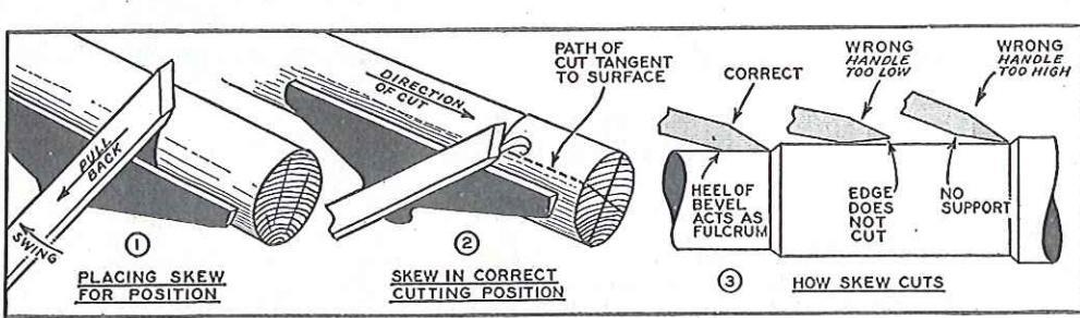
SMOOTHING WHILE the gouge cuts A CYLINDER a fairly smooth surface when properly handled, the large skew is usually used The area, the final smoothing cut skew can travel in either direction. and the cut is generally from the center to either end. In making the smoothing cut, the skew is placed well over the work, Fig. 1, and is then pulled back until the edge begins to cut The handle is then swung slightly gway from the direction of travel, and the cut carried toward and off the end of the work, Fig. 2. With a little practice, the initial placement of the chisel, Fig. 1, can be eliminated, contacting the work direct, as in Fig. 2.
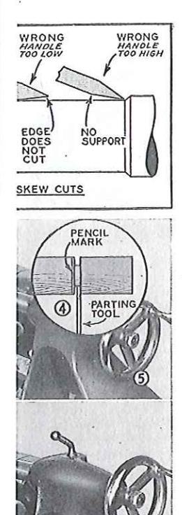
HOW SKEW DIAGRAM Fig. 3 CUTS shows how the skew cuts. Note that the herel of the bevel serves as a ful-
rrum. Lowering the handle decreases the "bite." In this position the edge will not cut at all on first contacting the work. Raising the handle increases the depth of cut. This is done gradually so that the heel of bevel supports the chisel. Starting with the handle high is incorrect and may cause a "run."
CUTTING A SHOULDER THE parting tool is used first to establish the approximate position and depth, is in Fig. 4.
SHOULDER The gouge cleans out the waste, Fig. 5. The skew is used in the regular position to smooth the shoulder, the cut running off the end of the work. In making the smoothing cut directly at the shoulder, the skew is started in the usual position and is gradually pushing forward until the heel is making the cut. This position allows the chisel to work right into the corner of the shoulder, Fig. 6. The edge of the shoulder is cleaned by making a cut with the toe of the skew, as in Fig. 7. The left hand example in Fig. 8 shows the incorrect position of the chisel for this operation. Note that the whole bevel is in contact with the

Below, only the extreme point o chisel is used in trimming a shoulder

work. Thi run. The i that the k providing a is turned a cutting. Th manipulatia at the lath
V E E GROOVES
action is the except that required be cut is madin successicut to the iner is con clearance wood) par the turning picture the the heel of tion, as inc Fig. 2, is with the ipush. Both the princip on opposite treme to eo full edge o
CUTTING BEADS
cut at the surfaces wi This scoring toe of the s the skew. flat at the From this gradually the cut, Fig of the beg ner. Smal scoring bein cuts until obtained. observe in only the ex


y the extreme point of ed in trimming a shoulder.

work. This position will cause the chisel to run. The right hand example is correct. Note that the bevel is in contact with the work, providing a support, but that the cutting edge is turned away so that only the extreme toe is cutting. This is an important principle in skew manipulation and should be observed directly at the lathe with chisel in hand.
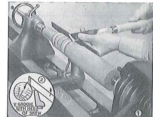
VEE VEE grooves can be cut with either GROOVES the toe or heel of the skew chisel. When the toe is used, the cutting
When the toe is used, the cutting action is the same as in trimming a shoulder, except that the chisel is tilted to cut at the required bevel, Fig. 9 on opposite page. The cut is made progressively, taking a small bite in successive cuts until the groove has been cut to the size required. Cutting in this man-
cut to the size required. Cutting in ner is commonly used in making clearance cuts (removing excess wood) particularly at the ends of the turning. Figs. 1 and 2 at right picture the vee-groove as cut with the heel of the skew. A hinge action, as indicated by the arrows in Fig. 2, is used, whereas cutting with the toe employs a straight push. Both methods must observe the principle illustrated in Fig. 8 on opposite page—cut only with extreme toe or heel; never engage the full edge of chisel.
CUTTING THE size of the bead is first marked with pencil
lines, and a groove is cut at the point where the curved surfaces will come together, Fig. 3. This scoring cut is made with the toe of the skew. Actual cutting of the bead is done with the heal of the skew, the chisel being nearly flat at the start of the cut. Fig. 4 From this position, the skew is aradually rolled to the center of the cut, Fig. 5. The opposite side ner. Small beads are formed by making one cut on each side. Large beads require two or more cuts, the scoring being alternated with side cuts until the required shape is obtained. The essential point to observe in cutting beads is that only the extreme heel of the skew
Cutting a cove with the gouge is one of the most difficult cuts in wood turning.
lee grooves can be cut with the heel of skew. Left. cutting a bedd
does the cutting. This means that the bevel of the chisel must at all times be tangent to the work, Fig. 6. Beads are hard to cut, and the slower but surer method of scraping with the diamond point chisel, Fig. 7, is recommended for occasional turning.
THE cove cut is made COVES with the gouge. Pencil marks are used to indicate the position of the cut. Excess wood position of the cut. Excess wood is roughed out with the gouge in a scraping position, Fig. 8. If desired, the complete cut can be made by scraping with the gouge or round nose chisel. The action of cutting a cove after roughing is shown in Figs. 9, 10 and 11. At the start of the cut, the gouge is swund so that the bevel is at right angles to the work and the chisel pointing directly to the center of the revolving spindle. Fig. 9. From this position, the gouge is rolled and pushed forward, Fig. 10, completing the cut at the bottom of the cove, Fig. 11. The opposite side is cut in the same manner, alternating cuts until the required depth has been reached. The cove cut, together with the head are the two most difficult cuts in spindle turning. The occasional turner is advised to make these cuts by scraping


TURNING A SPINDLE HAVING mastered the basic cuts, the turner is in a position to turn finished spindles. A typical turning, as shown in project plans, is pictured in Fig. 1. In making this turning, the work is first squared up to the size of the square section—2¼ inch. The work can be cut the same exact length as the turning, providing the center marks are not objectionable and the size of the work large enough to ac-
commodate the centers. In most cases, how-ever, the work is left a little long at one or ever, the work is left a little long at one or both ends to allow for trimming. After mounting in the lathe, the work, with the exception of the square section, is rough turned with the large gouge to a maximum-size cylinder. The cut surface should be smooth enough to take cut surface should be smooth enough to take pencil marks. The various dimensions along the length of the spindle are then marked. but one turning is to be made, it is practical to lay off the dimensions with an ordinary rule Fig. 3. The pencil marks should be made visible when the work is revolved under power and can be guickly traced around the cylinder and can be quickly traced around the cymaer by touching each line with a pencil while the work is revolving. An optional method is to hold the pencil against each mark and revolve the spindle by hand. After marking. the parting tool is used to make sizing cuts at all important shoulders, Fig. 2. The cut must always be in the waste stock. The tolerance for finish cuts should be from zero to 1/8 inch. The best practice is to cut all shoulders and straight surfaces practically net size, leaving just enough wood for a shaving cut with the skew. Curved surfaces should be left rather full, and need not be sized at all in most cases since their diameter is usually easy to judge from adjoining shoulders. Once the sizing cuts are run in, turning is simply a matter of roughing out the excess wood with and proceeding with the various cuts.
DUPLICATE TURNINGS TURNINGS THE pattern or layout board is simply a thin piece of wood or cardboard on which is drawn a full-size half section of the turning. Placing the pattern against the cylinder, Fig. 4, the turner can quickly mark the various points. Many turners do this with the work revolving, especially when there is no square section. Marks across the pattern show the diameter of the turning at essential points, and the caliper is set to these marks, Fig. 5, for the sizing cuts. After sizing, the pattern is tacked to the lathe bench or hung behind the lathe where it serves as a general guide.
USING THE STEADY tern REST app turning. Its print to provide a cent long, slender tur which would othe excessively. In is first turned do der shape at sor the center of th at least 1/8 inch o for cleaning up.
not too tightly an must be lubricat metal, any kind a if wood, the best ing can then pr working on eith Speeds a step sl used to prevent e ing is complete, t shifted to some a that the contact
BACK A SII STICK rest i 2. T piece of wood or an extra tool res
of being fitted at
END TURNING as shown in Fig.
between centers lashed to the lar rawhide, as show in place througho not be necessary the lathe. The st before backing off up has been mad turning is cut off, can be turned as removed, the set-u mit sanding the
LONG TURN TURNINGS capac turned extension. This is which can be mot

In most cases, how a little long at one or rimming. Alter mounts rough turned with the mum-size cylinder smooth enough to take rious dimensions along le are then marked. If s with an ordinary rule. arks should be made They will then be is revolved under power ced around the cylinder a with a pencil while An optional method raginst each mark and hand. After marking I to make sizing cuts at , Fig. 2. The cut must e stock. The tolerance > cut all shoulders and ically net size, leaving a shaving cut with the s should be left rather sized at all in most sized of off in most houlders Once the sizurning is simply a matthe excess wood with with the various cuts
ATE turnings should be with the use of a patorder to insure accuracy. board is simply a thin oard on which is drawn of the turning. Placing ie cylinder, Fig. 4, the ark the various points. is no square section. tern show the diameter sential points, and the + marks, Fig. 5, for the ig, the pattern is tacked hung behind the lathe general guide.

HEING THE steady or centor rest has many DECT applications in wood and metal turning. Its prime purpose is to provide a center support for
long slender turnings. Fig. 1. which would otherwise vibrate excessively. In use the work is first turned down to a cylinder shape at some point near the center of the turning leaving the stock
at least 1/8 inch over finished diameter to allow for cleaning up. The steady rest is then fitted in place, adjusting the jaws to fit firmly but not too tightly around the turning. The work must be lubricated at the contact point. If metal, any kind of oil or arease can be used: if wood, the best lubricant is beeswax. Turning can then proceed in the usual monner. working on either side of the steady rest Speeds a step slower than normal should be used to prevent excessive hurning. After turning is complete, the steady rest is removed or shifted to some other point of the turning so that the contact area can be cleaned up
STICK
A SIMPLE substitute for the steady rest is the back stick shown in Fig. This is simply a vee-notched piece of wood on a metal shank mounted in an extra tool rest base to form a support at rear of turning. It has the obvious advantage of being fitted at any place along the turning.
SPINDLES which must be turned END TURNING at the extreme end can be worked with the use of the steady rest. as shown in Fig. 4. The work is first turned between centers in the usual manner; then lashed to the large faceplate with twine or rawhide, as shown. The faceplate should be in place throughout the turning so that it will not be necessary to remove the work from the lathe. The steady rest should be adjusted before backing off the tailstock. After the setup has been made, the excess wood at end of turning is cut off, after which the end of work can be turned as required. With steady rest removed, the set-up is sufficiently rigid to permit sanding the burned area. Fig. 3.
TURNINGS longer than the normal TURNINGS tonger from the norman capacity of the lathe can be turned by purchasing a lathe bed extension. This is a short length of lathe bed, which can be mounted on the bench at end of

lathe. It takes the tailstock, and work is mounted and turned in the usual manner. For occasional long work of this kind, it is practical to mount the tailstock on the drill press table adjusting the table to the proper height and locating the drill press at the required distance away from end of lathe to accommodate the turning stock. Generally, all long turnings are more satisfactorily worked in shorter sections. ed sections or shoulders so that the final assembly of pieces looks like a solid, one-piece turning. Boring for dowel holes can be done on the lathe, and the dowel, fitted in end of work, will also support the turning for cleanup cuts at the joint
LATHE BUTTON your sleeves tight at the wrist or roll them up past your SAFETY elbow Beware of a loose, dan aling necktie or any other clothing which might become entangled in the revolving work. Make Always spin the set-up by hand before throwing switch. If you use a reversing switch, block off the reverse with some simple lever so that you won't pull it accidentally. Keep the tool rest close to the work. Keep your chisels sharp. Don't be afraid of high turning speeds on ordinary spindle work.

Faceplate and Chuck TURNING
MOUNTING WORK ON FACEPLATE WORK on a faceplate or some kind of standard or special chuck The
greater part of all work of this kind is mounted on the 31/2-inch faceplate. In preparing the stock, the approximate cen-
ter should be located and a circle drawn to indicate the size of the turning. A second circle should be drawn to indicate the location of the faceplate, Fig. 1. The work is roughly band sawed to the required size. The faceplate is then attached to the work, using 10 or 12gage flat head screws of
suitable length, Fig. 2. A ¾ inch screw length is a good stock size for all types of faceplate turning. It is good practice to make a file mark on the faceplate and a corresponding mark on the wood, as shown in Fig. 2, so that the work can be relocated at the same posi-tion in the event of removal from the force nlate before turning is complete. Fig. 3 shows the work mounted on the faceplate. It will be noted that the screws do not interfere with the cutting of the required shape. Fig. 4 shows the cutting of the required shape. Fig. 4 shows α turning which, if mounted directly to the faceplate. could not be turned because the screws would project into the turned pertion In work of this kind. a backing block is used In some instances, Fig. 4 for example, the work can then be screwed to the backing block. In can then be screwed to the backing block. In other jobs, screw holes are not permissible, and in this event the work is glued to the backing block, using a sheet of paper at the alued joint so that the work can be easily separated from the backing block when turning is complete.
POSITION OF TOOL REST low the center of work. DIAGRAM Fig. 5 shows the position of the tool rest in faceplate turning—1/s inch be-

plate. Below, cutting work to cylinder and facing with large skew.


CUTTING THE firs WORK TO squaring CYLINDER This is d in Fig. 6. The face of On work under 6 in shown in Fig. 7 cives
VARIOUS CUTS Urning c and 10. gouge being used to shows various appli chisels. Fig. 10 is cutting the cylinder point chisel. It should plate cuts are scrap is projected squarely ting technique, as de ing, cannot be used size of the work an grain of the wood. D the work are convenie of dividers, as shown both legs (important)
DEEP RECESSES IF A slid best meth recess is metal boring bar, as first removing as much by boring with the lar Fig. 12. If the opera turning chisels, the rec the round nose chisel, squared with the skew tom is squared with a chisel, Fig. 16. A chi squareness can be ma Note the positions of to 15 to obtain maximum

¾ inch screw length ll types of faceplate tice to make a file nd a corresponding wn in Fig. 2, so that wn in Fig. 2, so that d at the same posi-oval from the facenplete. Fig. 3 shows faceplate. It will be shape Fig 4 shows shape. Fig. 4 shows turned because the the turned nortion. the turned portion or example, the work 1e backing block. In are not permissible. ork is glued to the leet of paper at the work can be easily a block when turn-
I Fig. 5 shows the of the tool rest in turning_1/2 inch he-

All cuts in faceplate work All cuts in taceplate work are made scraping. Photo below shows dimensions are set off with divid
CUTTING THE first turning operation CYLINDER THE first turning operation is squaring the edge of the work. This is done with the gouge, pro-jecting the chisel squarely into the work to make a scraping cut. as shown the work to make a scraping cut, as shown in Fig. 6. The face of the work is then squared. On work under 6 inch diameter, the method shown in Fig. 7 gives a clean cut.
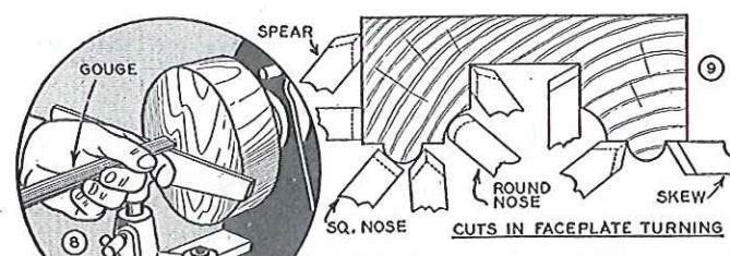
VARIOUS cuts used in faceplate VADIOUS turning are shown in Figs. 8, 9 and 10. Fig. 8 shows the large gouge being used to face the work. Fig. 9 gouge being used to tace the work. Fig. 9 shows various applications of the different chisels. Fig. 10 is an alternate method of cutting the cylinder shape, using the spear cutting the cylinder shape, using the spear plate cuts are scraping cuts — the chisel prote cuts are scraping cuts — the chisel is projected squarely into the wood. The cut-ting technique, as described for spindle turning tecnnique, as aescribed for spinate turn-ing, cannot be used because of the larger size of the work and the difference in the grain of the wood. Dimensions on the face of grain of the wood. Dimensions on the face of the work are conveniently set off with the use of dividers, as shown in Fig. 11, supporting both legs (important) on the tool rest.
IF A slide rest is available, the DEEP RECESSES best method of, cutting a deep best is to hore it out with a metal boring bar, as shown in Fig. 13, after first removing as much excess wood as possible by boring with the largest wood bit available. If the operation is to be done with Fig. 12. Fig. 12. If the operation is to be done with turning chisels, the recess is first roughed with turning cmisels, the recess is first roughed with the round nose chisel, Fig. 14. The sides are squared with the skew, Fig. 15, while the bot-tom is squared with an ordinary square nose chisel, Fig. 16. A check for both depth and squareness can be made as shown in Fig. 17. Note the positions of tool rest in Figs. 14 and 15 to obtain maximum support.


Successive steps in turning a box. In all faceplate work, time is saved by roughly band sawing the circular shape before turning.
TURNED TURNED boxes involve deep recessing to-
TURNED JORNED boxes involve deep recessing together with a special system of working the lid and body of box together as one unit. The idea is illustrated in Figs. 1 to 4 above. The inside of lid is turned first, followed by inside of body. Careful check must be made when turning lip of body so that the lid will be a tight press fit. Fig. 4 shows the lid fitted over body for external turning. After turning is complete the lid joint can be relieved for an easy fit. The backing block, glued in place with paper at the joint, is split off by inserting a chisel with the grain.
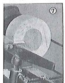
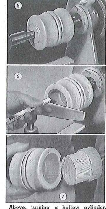
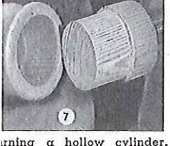
CYLINDERS STOCK for cylinders should be mounted on the single screw center or small faceplate. The tailstock center can be brought up to support the work while the outside is being turned to shape, Fig. 5. Next, the tailstock is backed off and the outer end of cylinder is recessed, Fig. 6. The work is then removed from screw center. The screw center is used to mount a length of softwood stock which is turned down so that the cylinder will be a tight press (not driving) fit over it, Fig. 7. Mounted on the wooden chuck, the hole can be turned from the opposite end to complete the job.
PLUG A PLUG chuck is an auxiliary wood chuck CHUCKING a auxiliary wood chuck is an auxiliary wood chuck mounted on a faceplate. The chuck should be about 2½ inches thick by 3½ inch diam-
eter, with a 3/4 or 7/8-inch hole in center, as shown in Fig. 8. This is a permanent chuck and should be well made and permanently mounted on faceplate. It is useful for turning balls, goblets, etc. In use, the wood stock for turning is turned between centers, Fig. 9, so that the tenon will be a driving fit in hole in plug chuck. Fig. 10 shows work being turned while held by plug chuck.
RECHUCKING RECHUCKING is the general term used to A BOWL describe any additional work mounting necessary to complete a turned project. The method of working cylinders and the use of a plug
Below, method of plug chucking goblets and similar work.


Above, 1
chuck, c ical exa bowl, th wood b the usuc auxiliar; made u accomm press fil bowl m of rechu
ject is tom slig so bowl
PICTUR
in Fig. 4 saw out a woode rabbet Fig. 6 s chuck, r
TURNED BALLS
the requ ter and marked ' 7. With plate, th Fig. 8. using th close to advance-Finish si chuck, F center is for finish shown i cup chuc never me with a d centers r
the first opposite


thod of plug chucking gob-


Above, rechucking a turned bowl. Drawing at right shows method of making turned picture frames.
chuck, as already described, are typical examples. As applied to a turned bowl, the work is first mounted on a wood backing block and turned in the usual manner, Fig. 1 above. An auxiliary chuck of softwood is now made up, this having a recess to accommodate the bowl in a tight press fit, Fig. 2. Fig. 3 shows the bowl mounted in chuck. The idea of rechucking a bowl or similar project is to permit recessing the bottom slightly, as can be seen in photo, so bowl will have a level base.
PICTURE MOUNT the work on faceplate and turn the glass rabbet, as shown in Fig. 4. Use the jig saw to roughly saw out the center of frame. Make a wooden chuck which will grip the rabbet in frame, Fig. 5. Diagram Fig. 6 shows the work mounted on chuck, ready for finish turning.
TURNED THE wood stock is BALLS mounted on faceplate, allowance being made for waste. The work is turned to the required diameter and the center and inner limit of ball shape is marked with pencil, as shown in Fig. 7. With the use of a plywood template, the outer half of ball is turned to shape,
plate, the outer half of ball is turned to shape, Fig. 8. Continuing the operation, always using the template as soon as the work gets close to finish size, the shape is gradually advanced, Fig. 9, and the ball finally cut free. Finish sanding can be done in a deep cup chuck, Fig. 10. If a ball bearing tailstock center is available, the work can be mounted for finish turning and sanding by the method shown in Fig. 11. In turning with use of cup chuck, the ball must be constantly shifted, never more than an eighth turn, and always with a definite system. Since turning between centers makes the ball a perfect sphere across the grain, it must be mounted in chuck so that the first scraping cuts will round it up in the opposite direction.

Above, tempiate is useful in ball turning. Below large work mounted on outboard end of spindle


Built-up segment rims are used for large faceplate work and are very decorative when worked into bowls and boxes.
OUTBOARD FACEPLATE work which is too large to swing on inboard end of spindle can be mounted on large faceplate, which has both right and left hand threads, and turned on outboard end of spindle as shown in Fig. 12 on previous page. For occasional as shown in Fig. 12 on previous page. For occasional work, a satisfactory tool support can be obtained by clamp-ing the tool rest to the table of a floor model drill press. as shown.
SEGMENT
SEGMENT howls and hoxes illustrate built-up work as applied to faceplate turning. Other TURNINGS work as applied to taceplate turning. Other than being attractive, built-up work of this kind is often the only practical method of making circular rims for tables, etc., where a solid block of wood would be almost impossible to obtain, and, even if used, would be
very likely to warp. The general method used in doing The segments required are first cut on the circular above. The segments required are first cut on the circular saw. The bowl requires twelve pieces, although this can saw. The bown requires twelve pieces, although this can be worked with six or eight pieces if desired. To make a 12-piece bowl, a board about % by 3 by 30-inches is cut into pieces about 2½ inches long, the saw table being tilted 15 degrees and the board turned alternately face up and face down to make successive cuts. The twelve pieces are glued together and clamped by wrapping the assembly with wire, after which the segment rim is alued to a temporary circular backing, as shown in Fig. I faceplate is attached to the center of the backing and the work mounted on the lathe. A recess of the largest possible diameter and about 3/4 inches deep is turned in the open end of the work, as shown in Fig. 2. The bottom of the bowl is mounted on a second faceplate and a rim about 1/8 inch deep is turned to exactly fit the recess previously turned on the work. The bowl is then fitted over the bottom and glued, Fig. 3, making a drum shape with a faceplate at each end. The drum is cut completely in two at a point about 3/4 inch above the bottom. Fig. 4. completing the cut with a hand saw. Both parts of the cut surface are faced off square and smooth and then requed, as shown in Fig. 5. breaking the joints exactly half and half. The cutting and reglueing process is repeated with a section about 1¼ inches wide, and then again with a section about ¾ inches wide. The temporary backing block is then cut off, leaving the bowl as shown in Fig. 6. From this point, the work is simply a job of turning, making the bowl of any desired shape.
Spec
REDUCED TU SQUARES SIT
reduced square in photo is or ing a spindle cutting the rea l or band so note method to build it up ing one dimen size, as shown alter applicati gives a perfect which to glue secondary co which should to match the possible. As i to assure conc
INLAY BY TURNING a
Fig. 7 is a sim is not matche much as possi example, map tain the desire the various la rushed. Each to dry, and an


ge faceplate work and to bowls and boxes.
i is too large to swing idle can be mounted ch has both right and board end of spindle, bage. For occasional be obtained by clampoor model drill press,
oxes illustrate built-up splate turning. Other built-up work of this od of making circular ock of wood would be ven if used, would be nethod used in doing bowl shown in photo irst cut on the circular ces although this can ces, although this can f desired. To make a by 3 by 30-inches is t, the saw table being imed alternately face ive cuts. The twelve ped by wrapping the segment rim is glued shown in Fig. 1. A f the backing and the iss of the largest posdeep is turned in the 1 Fig. 2. The bottom 1 faceplate and a rim ctly fit the recess preowl is then fitted over ig a drum shape with a is cut completely in ve the bottom, Fig. 4, .w. Both parts of the and smooth and then ing the joints exactly glueing process is renches wide, and then wide The temporary ig the bowl as shown rk is simply a job of esired shape.
Special SPINDLES
REDUCED TURNINGS having a square section SQUARES smaller than the largest turned section are known as turnings with reduced squares. The turning at right center in photo is an example. The best way of working a spindle like this is to use solid stock
ing a spindle like this is to use solid stock, cutting the reduced square on the jointer, Fig. 1, or band saw, Fig. 2. Since this method is expensive and sometimes impossible, the alternate method of post blocking, Fig. 3, is often used, blocks being glued to the square section to build it up to the required size. The most important point to observe in post blocking is perfect glue joints. This is best done by leaving one dimension of the square a trifle oversize, as shown in Fig. 4, jointing to net size after application of the first set of blocks. This gives a perfectly level and accurate surface on which to glue the second set of blocks. A secondary consideration is the wood itself, which should be selected for color and grain to match the original square as closely as
possible. As in all turnings having a square section, accurate centering on the lathe is important in order to assure concentricity.
INLAY BY carrying the post blocking principle TURNING a step further, an attractive type of turning resembling inlay work can be made. Fig. 7 is a simple example. In this case, the wood is not matched, but rather selected to contrast as much as possible with the wood it adjoins. In the example, maple and walnut have been used to obtain the desired separation. Fig. 5 shows the assembly, while Fig. 6 shows how turning will expose the various layers of wood. It can be seen that most of the work in a turning of this kind is the build-up of the various woods. The job cannot be rushed. Each pair of blocks must be fitted, allowed to dry, and are then jointed flush for the applica-

Above, special spindles, reading from outside of page: Oval, spiral, post blocked, fluted, combination and club foot.


uniformity must be observed since otherwise the turning will show out-of-balance sections when turned. The principle of inlay turning has many applications; plans for lamps, candlesticks, boxes, etc., can be found in the various craft and mechanical magazines. Since the wood is selected for natural color, the work must be finished natural.

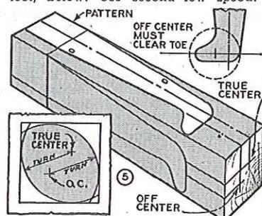
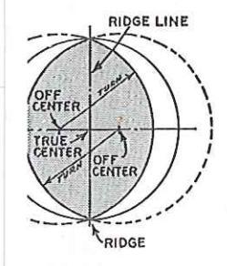
OVAL OVAL turnings are oval in cross section instead of the usual full round. A hammer handle is a common example. The shape is obtained by turning the work on two off-center turns one side of the spindle to the oval shape, the two ovals meeting in a sharp line called the ridge line. Work of this kind should be laid out full-size on paper, using a compass to determine the amount of off-centering required to obtain a certain shape, as shown in Fig. 2. After finding the amount of off-centering required, the three centers are marked on each end of the work. The stock is mounted on true
centers and turned to the required shape, but fat, since a little wood will be lost in the final softening of the ridge line. The ridge line is marked on the spindle after true turning, as shown in Fig. 1. The work is then off-centered and turned (use second low speed) until the cut comes exactly to the ridge line. This is easily done without stopping the lathe because the work shows a double image as it revolves Fig. 3 shows the shape with one side finished. The work is now mounted on with one side inished. The work is now incumed on the other pair of off-centers and again turned until the cut comes to the ridge line, Fig. 4. A light cut with the work on true centers will remove the sharp ridge line, after which sanding will further soften the shape to a true oval. It will be apparent that the original shape of stock can be rectangular and need not be square as for ordinary spindle work. In most cases an allowance of 1 inch of unturned stock must be made at either end of the spindle. Figs. 3 and 4 show the cut carried out to the end of the work in order to show the shape, but it can be seen that this destroys wood in which to recess the centers


CLUR FOOT of the square is corr off-cen this en only) work a tion. error ing on THE CARDI LEG lathe c serves patterr


THE club or Dutch foot on turned CLUB spindles is another process involv-FOOT ing off-centering. A paper pattern of the leg is first made, and the shape transferred to two adjoining sides of the turning square. Fig. 5, opposite page. The true center is carried out to either end of the work. The off-center is marked only on the club foot end. this end of the work being held by tailstock. As in oval turning, the off-center is found by experimenting with a compass. A point to observe is that the turning circle ground the off-center must clear the toe of the foot, as shown in Fig. 5. After marking the shape, waste stock can be removed by compound sawing on the band saw. This is not essential, but saves a lot of extra turning. Turning is done with the work on true centers, the shape being cut to finished size. Fig. 8. This will turn the toe of the foot but not the heel The spindle is now off-centered (tailstock end only) and turned to remove wood at the heel of the foot to obtain the shape shown in Fig. 6. The lathe should run in second low speed There is no double image in this case and the work must be stopped frequently for examination. Guard against over-cutting, which is an error easily made. After turning the heel, error easily made. After turning the heel, there will be a sharp ridge line where the two circular arcs come together. This should be softened with a few strokes of a file. Sanding on both off and true centers, Fig. 7, will then smooth the foot to a pleasing club shape.
THE THE cabriole leg, extensively used CABRIOLE in the construction of French period furniture, is largely a product LEG of the band saw. However, the lathe can be used to turn the foot, and also serves as a handy holding device for hand
modeling. Work of this kind requires a paper pattern, which is used to transfer the shape to adjacent sides of the wood stock. If the foot is to be turned, the turning center should be marked, as in Fig. 1. The work is com-pound band sawed, Fig. 3, and is then ready
for turning. Only the foot can be turned, since the shape is not symmetrical above the extreme projection of toe, although a few light cuts can be taken to advantage on the heel of the leg for a distance of an inch or so above the toe. The work can be off-centered to turn the shape above the toe projection. but since the leg requires considerable handwork in any event, this extra turning is hardly worthwhile. Hand shaping with coarse wood files is conveniently done with the work mounted in the lathe, as shown in Fig. 4.
COMBINATION THE rear leas of chairs and stools sometimes involves a TURNINGS combination turning, the low-
er part of lea being a regular turning while the upper part is straight or shaped and at an angle to the lower turned portion. of this kind can be made in two parts, doweled together, as shown in Fig. 5. A second method is to turn the work first and then saw out the straight section, Fig. 6. In method No. 3, the straight shape is sawed first, after which a waste strip of wood is alued in place with paper at the joint to provide stock for the live center, Fig. 7. After turning, the waste stock is stripped from the turning by tapping it sharply with a hammer.


FLUTING and
various cuts in fluting and reeding turned spindles is already in-corporated in the construction of REEDING the lathe in the indexing head. This provides for setting off from 2 to 60 equal spaces, as aiven in the table on page 32. A typical jig for doing the actual cutting is shown in Figs. 1, 2 and 3. This makes use of standard shaper cutters, the cutter being mounted and driven by means of a flexible shaft. The end of the shaft housing is firmly mounted between two blocks of wood, and is arranged to slide along a wooden auide bar, as shown in Fig 3. The a wooden guide bar, as shown in rig 3. The depth of cut is controlled by means of a depth collar, Fig. 2. Slight burning in softwood is collar, Fig. 2. Slight burning in source as easily removed by sanding the work after fluting. If the operation is reeding, each new cut should be set by turning the work clockwise (as viewed from tailstock) so that the collar will ride solid wood on all but the last collar will rate solid wood on all but the last cut. The jig can be used on either straight or curved work. The jig shown is but one of several devices capable of doing good fluting on the lathe if properly set up. Speaking generally, the operation is more satisfactorily done with the use of a fluting ig on the shaper.
THE mechanism for spacing the
S P L I T A SPLIT turning generally implies TURNINGS α spindle which is one-half of α full circle. However, the same term applies to quarter-rounds and other sections cut from a full turning. Fig. 4 shows various examples. In making up the stock two pieces of wood are alued or screwed together to form a square. If the work is glued, a piece of paper is used between the two blocks, as in Fig. 5, to allow easy separation of the work after turning. Screw fasten-ings are ideal for all short spindles, Fig. 6, The assembled square is turned in the usual manner. If screw-fastened, the removal of the screws will separate the work into two the screws will separate the work into two split turnings. If glued, the work is separated by using a knife or chisel, as shown in Fig. 8, causing it to split cleanly at the papered joint.

lf, quarter, or small photo above,

TWIST TURNIN
lathe is the cyli work th with coo twist double thread lead is advance
complete


PLIT TURNING
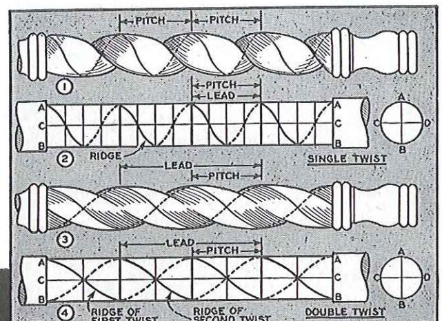
TWIST TWIST or spiral TUDNINGS turnings are mainly work. The lethe is used only for roughing the cylinder and holding the work the twist itself is fachioned with coarse-cut files and sandpa-The two common types of turning are single and twist turning are single and drawing. Like any ordinary screw drawing. Like any ordinary screw thread, the pitch is the distance between threads or ridges: the lead is the distance the thread advances in making a sinale complete turn ground the work.


Cutting is largely a matter of hand filing. The lathe is not under power except for sanding.
By dividing the length of work into α number of small spaces, the ridge of the twist can be accurately marked.
In a single twist, the pitch and lead are the same; in a double twist, the lead is twice the pitch. The pitch can be any suitable length, usually no less than the diameter of the work.
MARKING FIG. 2 shows how the single twist is THE TWIST each space representing the pitch. Each main space is then marked off into four smaller divisions. Four lines are drawn parallel with the
sions. Four lines are drawn parallel with the work and quartering it, this being readily done by using the dividing head and guiding the pencil along the top of the tool rest. The ridge of the spiral can then be marked by crossing each of the small spaces, as shown in Fig. 5. A second spiral line to show the bottom or hollow of the twist is useful. The layout for the double spiral is much the same except each main division (pitch) is divided into two smaller spaces, as can be seen in Fig. 4. If the twist turning is tapered, the pitch is gradually reduced by an amount equal to the difference in diameters divided by the number of threads. Spirals can also be marked with a strip of paper wrapped around the turning, Fig. 6, but this method is not as accurate as mechanical spacing.
ACTUAL cutting is tedious but CUTTING THE SPIRAL not difficult. A saw cut is made on a line which represents the bottom of the groove, as shown in Fig. 7 each end of the twist, the saw cut should be straightened out somewhat, so that the cut follow more truly in a circle about the turning The depth of cut should be about one-quarter the diameter of work. After the saw cut has been made, the hollow of the twist is worked out, using a round file, as shown in Fig. 8. Next, a flat file is used to dress the round of the twist, as shown in Fig. 9. The penciled ridge line should be preserved throughout After smoothing as perfectly as possible by After smoothing as perfectly as possible by filing, cleaning up can be done by chasing the thread with sandpaper. This can be done with the lathe running at slow speed.

Elementary • METAL TURNING
EQUIPMENT WITH a few pieces of extra equipment, the wood lathe can be converted for metal turning, and will do all standard metal jobs with the exception of screw cutting. Basic extra is a compound slide rest. This clamps to the bed of the lathe and has two sliding tables operated by ball handles to give the controlled feed necessary for turning metal. Second major item is a countershaft, essential for speed reductions within the range of turning speeds for metal (see table on page 31). Lesser items of equipment include a 3-jaw chuck, 60 degree centers, lathe dogs, tool holders and tool bits.
MARKING
M A R K I N G and drilling the holes at either end of a piece of work to be turned between cen-
Work to be turned between centers is an important operation in metal turning. Two methods are commonly employed. When the work is short, it can be held in the 3-jaw chuck, as shown in Fig. 1. Revolving in this position, the end of the work is drilled with a center drill held in a drill chuck and advanced by means of the tailstock feed handle. In a variation of this method, the free end of the work is supported by means of the lathe steady rest, as shown in top photo. The second principal method of centering is shown in Fig. 2. In this set-up, the centers of the work are first located by means of a combination square or other method and the centers punch-marked. The work is then held in the
lathe as shown, the tailstock feed handle being used to advance the work to the drill mounted in headstock spindle. In both methods, the proper size of center drill should be used, as shown in tabular form in Fig. 3.
CHECKING WHERE extreme accuracy is re-GENTERS quired it is advisable to check
the accuracy of the punched center marks by revolving the work by hand between centers in the lathe, as shown in Fig. 5. A piece of chalk will locate any high spot, if present, and the error can be corrected by drifting the hole, as shown in Fig. 4. Center drilling by the method shown in Fig. 2 then follows to complete the operation.
WORK Shown in Fig. 1 on enposite
shown in Fig. 1 on opposite page. The work is supported at either end by a 60 degree center. The headstock end of work is clamped by a lathe dog, the tail of which engages one of the slots in the faceplate mounted on threaded headstock spindle. The tailstock center must always be lubricated. Lack of lubrication or too much pressure will cause a squeaky noise when the work is revolved under power, and such an indication requires immediate correction.

The two common methods of drilling work to be mounted between centers are shown in drawing above.

The work is by means o
TOOL BITS
Fig 2 Th ous styles ing A riv headstock. bit cuts fro outside to the name. shouldors ( work They along the smooth in i bits. The tool and ca This style of able in set at lower ric
RAKE AND CLEARANC
Angles on back take c of the tool side cleara steel, cast 5, 6, and 7 given in Fig tool holder imate bac is tilted up and is ther steel. Whe have the co tool holder. down, the is approxim able shape the tool ho back rake obtained by
lstock feed handle being 'ork to the drill mounted
In both methods, the drill should be used, as.
extreme accuracy is reit is advisable to check uracy of the punched ng the work by hand beithe, as shown in Fig. 5. I locate any high spot, or can be corrected by hown in Fig. 4. Center d shown in Fig. 2 then be operation
neral method of mountrk between centers is in Fig. 1 on opposite supported at either end . The headstock end of r lathe dog, the tail of f the slots in the faceaded headstock spindle. Ist always be lubricated. too much pressure will e when the work is rend such an indication rerection.


The work is mounted between centers and driven by means of a lathe dog which engages slot in faceplate. Right, various tool bits and cuts.
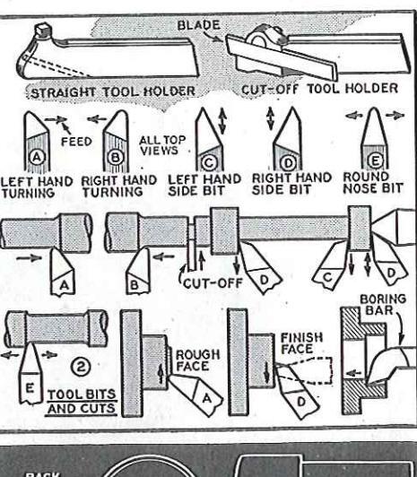
THE principal tool holder used TOOL BITS in metal turning is the straight AND CUTS tupo shown at top of drawing Fig. 2. This has a square hole to take vari-2. This has a square note in styles of shaped lathe bits. The cut-off ous styles of shaped lathe bits. The cut-our tool holder is a single-purpose tool, used for cutting-off and forming shoulders. shapes commonly used are shown in the draw-A right hand bit cuts from tailstock to ing. A right hand bit cuts from talistock to headstock, or, in faceplate work, from the in-side to the outside of the work. A left hand bit cuts from headstock to tailstock or from outside to inside. Side bits, as indicated by the name, are used to form the sides of the name, are used to form the sides of shoulders or for facing the end of a piece of snouncers or for facing the end of a piece of work. They can also be used for running cuts along the work, but are not so strong or as smooth in this capacity as the regular turning bits. The round nose bit is a general purpose tool and can be used in almost any position. This style of bit is used extensively for turning brass or soft copper. Boring bars are avail able in several sizes, and are used as shown able in several sizes, and are used as sho at lower right. Fig. 2 (See also page 24).
RAKE AND THE terms used to describe the CLEARANCE cutting portion of any lathe tool bit are shown in Figs. 3 and 4. Angles on the top of tool are called rakes. back rake and side rake. Angles on the sides of the tool are clearances, front clearance and side clearance. General-purpose anales for steel, cast iron and brass are shown in Figs. 5, 6, and 7. For occasional work, the angles given in Fig. 5 can be used successfully on all metals. This is accomplished by tilting the tool holder so that the bit assumes the approximate back rake angle for the metal being worked. As shown in Fig. 8, the tool holder is tilted upwards by means of the rocker ring, and is then approximately correct for turning When the holder is level, the bit will have the correct rake for cast iron, this being obtained by the angle of the bit slot in the tool holder. When the tool holder is tilted down, the bit assumes zero rake, Fig. 9, and is approximately correct for brass. For production work, the tool bits are ground to suitable shape instead of depending on tilting the tool holder. For example, Fig. 3 shows back rake ground on in addition to the rake obtained by inclined slot in tool holder.

Below, a scribed mark on tailstock ram serves as a quide for locating point of bit on centerline.


Facing to net length with use of chuck is often the first operation in turning a shaft. Drawing at right shows one method of cutting a shoulder.
POSITION THE tool bit OF TOOL should be housed well
housed well back in the slot with minimum projection. In most operations the tool holder should be adjusted at right angles to the path of cutting. The cutting point of tool should be at the center of the work, Figs. 3 and 4 on previous page. Since this setting must be made with reasonable exactness, and often, it is advisable to scribe a mark on tailstock ram as a guide, as shown in photo on previous page.
TURNING A TURNING α shoulder is one of the commonest lathe operations. To start, the work should be cut to net length, facing each end as in Fig. 1 above.
This gives an accurate surface for punching and drilling the center holes. If center holes are objectionable the work should be overlength to allow for trimming and the facing operation done with the work between centers. Fig. 2 shows the work between centers with the initial shoulder cut made with cut-off tool. Fig. 3 shows excess stock being removed. Fig. 4 shows the finishing cut. A right hand corner bit (A) is the best tool for this job, although the right hand side bit can be used in a pinch. Providing the work allows, the point of the tool should be slightly rounded. This will give a much smoother cut. After completing the shoulder, the work is reversed, Fig. 5, and the main body of shaft turned down to size.
TAPER TAPER turning is done by swiveling the compound to the required angle. When the angle of work is known, the compound angle is simply one-half the included work angle, as shown in Fig. 8. Turning is done in the usual manner, Fig. 7. It is important that the bit be exactly on center, otherwise the cut surface will not be straight. Fig. 6 shows the finished taper being cut off. Note in this photo how a right hand off-set tool holder permits working close to the chuck. When the angle is not given, the simple calculation shown in Fig. 9 should be made to determine the amount of taper per inch.
Left, compound swiveled fo turning a taper. Photo above shows use of cut-off tool.


DRILLING
in a chu does not stock. Th the drill chuck. I taper shu direct in 60 degre can be shown ir guides th clamping ilarly, a in a dep a second
SEENTER PLANE


ft, compound swiveled for ming a taper. Photo above shows use of cut-off tool.

DRILLING and Threading
DRILLING THE best practice in drilling on the lathe is to rotate the work in a chuck or similar device while the drill does not rotate but is advanced by the tailstock. The photo at right is a typical example, the drill or reamer being held in the drill chuck. If the drill is fitted with No. 2 Morse taper shank, it can of course, be mounted direct in tailstock ram. Many drills have a 60 degree center hole at end of shank and can be mounted and used by the method can be mounted and used by the method shown in Fig. 3 where a 60 degree center anides the drill while a lathe doa or similar clamping device keeps it from turning. Similarly, a pointed shank drill can be centered in a depression in the drill pad, Fig. 2. In a second general method of lathe drilling, the is mounted in the headstock while the work is stationary. Fig. 1, showing the pad center in use, is typical. Fig. 4 shows cross
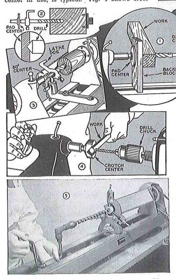

Photos and drawing illustrate various methods of drilling work mounted in the lathe.
drilling round stock with the use of the crotch center. In all cases, the same general method of working applies to both wood and metal.
DEEP WHEN the work is HOLES too long to be properly supported by the chuck alone, drilling can be done by using steady rest to hold free end of work, 20). A somewhat different
(see page 20). (see page 20). A somewhat different application of the steady rest in end drilling is shown in Fig. 5, where the steady rest is used to center a wood or metal bushing which supplies a guide for the drill. The photo shows how an ordinary brace can be used to advance the drill when the combined length of work and drill prevents using the tail work and arm prevents using the tall-stock. This is a good method of end boring in wood. Almost any kind of drill or wood bit can be used if the work is straight-grain softwood. If the work is straight-grain softwood. If the grain pattern is twisted, any conven-tional type of wood bit (solid center, tional type of wood bit (solid center, hollow auger, double flute, etc.) will do good work if the spurs are ground off, leaving only the cutting lips. It can be seen that deep spurs will have a tend-ency to lead off with the grain instead of boring a straight hole. Even with the most careful set-up, some slight error in tracking can be expected, and for this reason the work should be sufficiently oversize to allow for trimming.


TAPS HAND threading with taps and AND dies make practical use of the DIES lathe for holding the work. A typical tapping operation is shown in illustration, Fig. 1, where a hole is being threaded in the end of a plastic rod. The lathe tailstock serves to center the tap so that it will enter squarely into the drilled hole. Hand pressure on the tailstock forces the tap into the work as the wrench turns it around. The most common type of tap is the taper tap, Fig. 3. This style of tap does not cut a full thread unless it extends entirely through the work. The plug tap is topered only at the
end and is used to follow the taper tap when putting threads to the bottom of a blind hole. The bottoming tap has full threads throughout.
USING THERE are many different types of dies. Simplest and cheapest is the solid die, Fig. 3, in either a square or
solid die, Fig. 3, in either a square or round pattern. Better grade dies usually have a screw adjustment so that they can be made slightly larger or smaller than normal size. The adjustment is useful for cutting tight or running fits, and also permits threading in two "bites" on large work. The die is held in . a stock, which consists of a collet to hold the die and a guide to center it on the work, together with two handles by which the die is turned. Fig. 2 shows how the stock and die is used for threading on the lathe. The work is held in the 3-jaw chuck, which is prevented from turning by clamping the tool rest under the jaws. The handles of most stocks are too long to clear the bed of a small lathe so that the usual practice is to use but one handle, changing this from end to end as the cut progresses. Similar to the taper tap, the die is slightly tapered so that it does not cut a full thread. When a full thread to a shoulder
The wood lathe is not fitted with a ead screw for thread cutting, but most hreads can be cut with ordinary taps and dies. Photo below shows horing.

is required, the stock and die can be reversed, Fig. 4. The tailstock is frequently used in some manner or other to guide the die, especially if the stock is not fitted with a guide. A commonly used method is shown in Fig. 5 where a threaded rod of the same size as required on the work is held in a chuck in the tailstock. The die is threaded onto the rod and can then be turned off the rod directly onto the work. Plenty of oil should be used in threading operations. The tap or die should be advanced half a turn at a time, backing off between bites to break the chip and clean the thread.
BORING THERE are several types of boring tools and mounting methods, the commonest set-up being a plain boring tool held direct in the tool post, as shown in Fig. 6. The shank of the tool should be below center and the point exactly on center, as shown in Figs. 7 and 8. This will automatically provide back rake. The best practice is to use the largest boring tool which will enter the hole. The tool should have a minimum amount of front clearance for a strong cutting edge. Note in Figs. 7 and 8 that small boring tools used in small holes require more front clearance.
HAI
TOC
ing t
be 11

ie is not litted with a thread cutting, but most cut with ordinary taps

and die can be reversed is frequently used in some guide the die, especially ted with a guide. A com-is shown in Fig. 5 where he same size as required in a chuck in the tailstock onto the rod and can then be used in threading op-r die should be advanced backing off between bites nd clean the thread.
e several types of boring e several types of boring mounting methods, the seing a plain boring tool al post, as shown in Fig. 6. ol should be below center ly on center, as shown in will automatically provide ist practice is to use the which will enter the hole in a minimum amount of strong cutting edge. Note at small boring tools used te more front clearance.
Hour to Turn DLASTICS
PLASTICS THERE are two general groups of plastics. Group No. 1 includes all phenol plastics moulded under heat and pres-
Bakelite and Formica are examples. CIIFA Group No. 2 includes all cast plastics of var-Group No. 2 includes all cast plastics of var-ious bases sold under such trade names as Catalin, Cast Bakelite, Marblette, Tenite and Trafford. The plastic used in craftwork is generally in Group No. 2. It is easy to turn, being a little harder than wood but much softer than any of the soft metals.
USING THE compound rest fitted with standard tool bits is invaluable CLIDE in plastic turning, especially for DEST facing, recessing and other oper-rage cylinders. Work of this kind
ations on large cylinders. ations on large cylinders. Work of this kind is conveniently mounted on the three jaw chuck gripping the work from the inside. The tool bit should be set on center and should have zero or minus 5-degree back rake. The have zero or minus 5-degree back rake.
STANDARD TOOLS wood turning HAND chisels are excel lant for turning plastics, using a scraping technique. tool rest should be slightly below center and the chisel handle held a little higher than the cutting edge for a negative rake. Fig. 1. Scraping tools (parting tool, spearbe used. The area contacted by the tool should be kept to a minimum. A large con-tact area, such as the full edge of spear chisel, will cause chatter with consequent chipping. Properly worked the chip comes off in a continucmp comes on in a continu-ous ribbon. In cold weather, plastic may become brittle and should be tempered in warm water for 'about ten minutes before turning.

Plastics are easily turned with either tool bits or turning chisels. Above, squaring end of cylinder. MOUNTING THE most useful mounting WORK device is the three jaw chuck. Where this is not available, cylinders can be mounted on a slightly tapered wooden mandrel. Fig. 2 Rods can be mounted between centers, using either the metal or wood turning mounting. Where the spur center is used, slots should be
BALLS PLASTIC balls are rough turned in the usual manner and then brought to perfect roundness by using a tube tool, Fig. 3. The tube should be slightly less in digmeter than the finished size of ball It can be brass or steel. around square across the end. The tool is used with or without a rest and is worked by swinging from side to side.
FORMED tools FORMED for cutting TOOLS beads, etc., are easily made by using
small shaper cutters clamped to a metal bar held in the compound tool post, Fig. 4. The width of cutter in contact with the work should not exceed 1/4 inch. Cutters wider than this will "bite," resulting in a fractured surface
Tube tool makes turning balls easy to


Sanding and • GRINDING
SANDING DISKS THE sanding disk is a metal plate with threaded shank which fits the inboard end of the lathe spindle. The abrasive paper is glued to the machined surface of the plate, using a quick-drying cement supplied for this purpose. Abrasive disks can be purchased or cut from the standard size of abrasive paper. A fully adjustable sanding table adds to the scope and convenience of sanding operations, but good
work can be done with a wooden table fitted to the tool rest slide. Sanding is always done on the near side of the wheel; working on the far side would kick the work upwards. Either second or third speed can be used.
DRUMS PURCHASED sanding drums are usually rubber cylinders which can be expanded to hold the abrasive sleeve in place. Similar cylinders turned on the lathe and covered with abrasive paper glued or tacked in place do satisfactory work and have the advantage that special sizes, tapers, etc., can be made. The drum is used mainly for sanding the edges of curved work. The squareness of the edge of work can be best retained by using a simple form of vertical fence, as shown in Fig. 1. Purchased sanding drums are commonly made with threaded hole to fit the grinding wheel arbor. To guard against loosening of the tapered shank while the drum is in operation, it is advisable to support the free end, using either a ball bearing or plain 60-degree center, Fig. 2.
GRINDING GRINDING wheels are mounted WHEELS on the grinding wheel arbor. Here again it is advisable to support the free end, Fig. 3. Fitted with grinding wheel, the lathe will do any standard grinding operation, and has the added advantage of precision set-ups made possible by the use of the slide rest. A 70-grit aluminum oxide wheel 6 inches diameter is recommended for all-purpose work. The lathe should run in third speed—2400 r.p.m.'
GRINDING THE rotary hand tool can be set WITH up on the slide rest for many OPERATION OPERATION ROTARY OPERATIONS IN PRESENT OPERATION ROTARY OPERATIONS IN PRESENT OPERATION OPERATIONS IN PRESENT TOOL STOCK OPERATION OPER

The lathe provides a perfect mounting for disks and drums. Pho at right shows a typical job with use of rotary tool.

ter of the who
runs off the wh Morse taper Morse taper s working loose held by mea and of spind wheel should highest speed muslin. A lo The buff is c against it as it my of sources cake or stick made, or ca in a double b etc., to form c
paper used we ing. Buffing giv pounds commo
POLISHING U METALS
per polishes r polished with 3 grease. The v satisfactory for very fine abra
SANDING T TURNINGS TI
ders, as shown done with a n best finishing c Worn 2/0 pape or 4/0 new pa is shown in Fi in order to pre ers, etc. It is c in reverse rota basswood, whi hard to sand c fuzz down to t not too long w cut them off cl

1 α wooden table fitted anding is always done wheel: working on the
wheel; working on the work upwards. Either can be used.
PD canding drums are ubbor onlindors which old the abrasive sleeve ders turned on the lathe rasive paper alued or sfactory work and have side sizes tapers etc um is used mainly for irved work. The square rk can be best retained m of vertical fence as m of vertical tence, as chased sanding drums ith threaded hole to fit To auard against d shank while the drum dvisable to support the a ball bearing or plain
3 wheels are mounted grinding wheel arbot. in it is advisable to , Fig. 3. Fitted with the will do any standand has the added adset-ups made possible ; rest. A 70-grit alumches diameter is recomwork. The lathe should :00 r.p.m.'
y hand tool can be set ie slide rest for many s in precision grinding. ctures a typical job f a worn 60-degree cenit being set at 30 deg jobs of this kind, the centered with the lathe in opposite rotation to rotation of both tools is grinding; internal grindng the rotation of lathe.

r disks and drums. Photo use of rotary tool.

BUFFING IN operations using buffs or polishing wheels, work should be held against the lower quar-
work should be held against the lower quarter of the wheel, as shown in Fig. 1, so that the wheel runs off the work. As in all jobs involving the using of a Morse taper shank for side pressure operations, the free end of arbor must be supported to prevent the shank from working loose. A much better set-up is to thread a 4/10 inch rod into the end of shank so that the arbor can be held by means of a washer and wing nut at the outboard end of spindle, Fig. 2. General buffing with a six inch wheel should be done with the lathe running at next to highest speed. The buff itself should be 20 to 36 layers of muslin. A loose buff runs soft and is good for final polishing; sewed buffs are somewhat harder. Three or four buffs can be mounted on the spindle to give more contact area. The buff is charged by holding an abrasive compound against it as it revolves. The abrasive compound is simply any of several fine abrasives bonded with wax to form a cake or stick. The compounds can be purchased readymade, or can be made in the shop by melting beeswax in a double boiler and adding fine punice, whiting, rouge, etc., to form a paste which can be made into cakes.
POLISHING THE schedule for polishing plastics starts with sanding. 150-grit should be used to remove tool marks, then, 240 and 400-grit wet-or-dry
paper used wet are used in succession for the final sanding. Buffing gives the final polish, using the polishing comnounds commonly supplied for this purpose.
POLISHING USE a loose muslin buff and run the lathe at highest speed. Aluminum is buffed with tripoli, followed by red rouge. Brass or copper polishes nicely with tripoli or emery. Cast iron is polished with 240-grit silicon carbide powder bonded with grease. The various all-purpose polishing compounds are satisfactory for all metals. These compounds are usually a very fine abrasive, such as lime, whiting or tripoli.
SANDING TURNINGS should be sanded with the lathe running in second low speed. A large sheet of sandpaper is useful for smoothing cylinders, as shown in Fig. 3; all other sanding operations are done with a narrow strip of abrasive paper, Fig. 4. The
done with a narrow strip of abrasive paper, Fig. 4. The best finishing grit is 3/0 for soft woods, 4/0 for hardwoods. Worn 2/0 paper is often used and is the equivalent of 3/0 or 4/0 new paper. The application of the sandpaper strip is shown in Figs. 5, 6, 7 and 8. Care must be exercised in order to prevent dubbing the corners of beads, shoulders, etc. It is good practice to finish sanding with the work in reverse rotation. This is particularly true when sanding basswood, white pine and mahogany. These woods are hard to sand clean since sanding simply packs the surface fuzz down to the wood, Fig. 9. Sanding very lightly and not too long with the lathe reversed will lift the fibers and cut them off clean, as shown in Fig. 10.
The lathe makes an excellent bulling head. Mounting with tie-rod through

Sanding should not take the place of urning. 4/0 paper applied lightly should clean the work.


the surface. The point of contact should be below center and the tool should be stroked below center and the tool should be stroked in a short arc from rim to the center. The first stage of the spinning is shown in Fig. 4 -the metal should not be pushed down at the center, which is the easiest part of the spinning, but instead should be spun tight to the chuck to make the bend at the rim nt io spinning should be carried out over the flat portion of the metal as far as the holding screws permit. It will be found that the metal screws permit. It will be found that the metal will lift from the chuck. The lathe should be stopped and the rim hammered flat, as in Fig. 5. Spinning is continued until the metal is down snug to the surface of the chuck after which the edge can be trimmed. Fig. 6.
THE best metal for spinning is pewter of 18 or 20-gage. This METALS metal is very easy to spin and requires no annealing. Copper is easy to spin as long annealing. Copper is easy to spin as long as it stays soft. However, the action of the tool causes it to harden and become springy, making it necessary to anneal it two or three times during the operation. This can be done over a gas plate, quenching the metal in cold water after a dull red color has been obtained.
1
SOUARE PIECE OF META
Motal SPINNING
HOLLOW SPINNING sheet metal into hollow chucks is one CHUCKS of the simplest methods of metal spinning and is well suited for making ash trays, coasters, and similar projects. The chuck should be made from hard maple. It is mounted on the 31/2 inch faceplate and turned to the required shape of the project. A shallow recess is turned to fit the metal disk, as can be seen in Figs. 1 and 3, and the disk is secured by means of four round head screws over washers around its circumference. Where a sauare piece of metal is available.
can be used and is preferable to the recessed rim since it leaves the face of the work clear. However, metal for spinning is usually pur-chased in disk form, making it necessary to use the recessed mounting.
SPINNING SPINNING is done at a speed THE DISK from 700 to 1300 r.p.m. using a special tool rest and special tools made for this purpose, as can be seen in the photos. Where regular equipment is not available, good work can be done with a 1 inch maple dowel, rounded at the working end. The metal is lubricated with grease, after which the spinning tool is brought to bear on
Simple projects such as ash trays are easily worked by spinning the metal into a hollow chuck 28
or two co about to
own by dissolve applied d when ruk
GENERA
TREATM
the case
the job i operation
operation
complete
be used.
oak and
beech. a do not i
THE WA FINISH
able as a rewaxing
Wax used
applied ( sary to 1
EDENCH POLISH
for smooth adding ty orange sh ing pad s ball form apply, st Saturate t drops of the pad 1 a nice fin of polish ] the oil is t possible s damp with at this sto
nt of contact should be tool should be stroked rim to the center rim to the center. The ning is snown in Fig. 4 lot be pushed down at the easiest part of the should be spun tight to arried out over the flat arried out over the lidit be found that the metal hammered flat, as in ontinued until the metal inforce of the chuck after e trimmed. Fig. 6.
metal for spinning is f 18 or 20-aaae. This a spin and requires no s ever to spin as long vever, the action of the en and become springy ) anneal it two or three tion This can be done nching the metal in cold color has been obtained

ays are easily worked o a hollow chuck.
FINISHING on the Latho
THE selection of a finish for GENEDAL turned work depends somewhat TREATMENT on the nature of the project. In
the case of a table or chair with turned leas. the job is usually assembled dry and finishing operations with lacquer or varnish follow any standard schedule. Where the turning is a complete project in itself, such as a turned box or a lamp base, various types of finishes apor a lamp base, various types of ministees ap-plied with the work revolving in the lathe can be used. In all finishes of all kinds whether applied on or away from the lathe, it is necessary to use paste wood filler to fill the pores of coarse argin bardwoods such as mahogany oak and walnut. Maple, birch poplar, cherry, beech, gum, etc., are close-grained woods and
THE WAX THIS finish is popular on turned FINISH work because it is easily and anickly applied it is not as dur-
able as other finishes but can be renewed by
able as other finishes but can be renewed by rewaxing at any time. The wax finish will not stand water or high heat. To apply, give the work one or two coats of thin shellac. Sand lightly when dry. Apply wax by brushing or with a soft cloth. Allow to flat out for wax by brushing or with a soft cloth. Anow to not out a soft cloth. A about ten minutes and then polish with a soft cloth. A about ten minutes and then polish with a soft cloth. A second coat of wax can be applied within one hour. The wax used can be any commercial paste wax, or make your own by shredding carnauba or beeswax in turpentine and dissolve in double boiler. Cake wax of any kind can be applied dry to revolving work and gives a very good polish when rubbed briskly with a cloth.
EDENCH POLISH
FRENCH polishing is the best finishing technique to use where the turning is a complete unit in itself. This type of finish is unsurpassed
for smoothness and high gloss. The polish itself is made by adding two parts of denatured alcohol to one part white or orange shellac. Application of the polish is made with work revolving in the lathe, using a soft, lintless cloth. The polish-ing pad should be in strip form for spindle work, Fig. 2, and ball form for large faceblate turnings, Figs. 3, 4 and 5. To apply, start the lathe running in low or second speed. Saturate the polishing pad with polish and add two or three drops of oil (linseed, poppy, lemon oil or white vaseline). Apply the pad to the revolving work. Use very little pressure on the first coat and a minimum amount of oil. Keep the pad moving. When it becomes dry, add more polish. As the finish builds up, it will become soft and tacky. Stop operations at this stage and allow the work to dry (3 or 4 hours) before applying a second coat. One coat alone gives a nice finish on maple. Coarse grain woods must be filled before polishing. Soft woods will absorb two or three coats of polish before the finish starts to body up. The purpose of the oil is to prevent the pad from sticking, but as little oil as possible should be used. For third and fourth coats, the polish should be further diluted with denatured alcohol. All coats after the third must be applied with the pad barely damp with the polish, and with firm pressure. A wet pad at this stage will cut through the finish previously applied Sanding with fine sandpaper between coats is good practice.
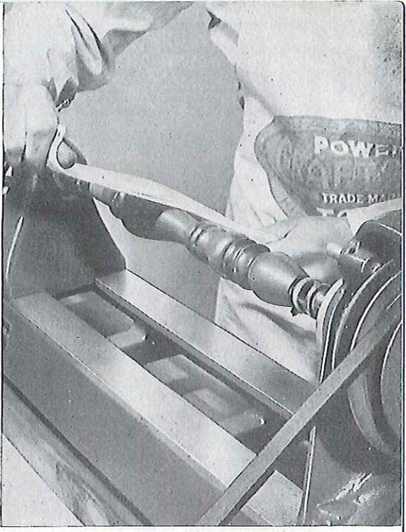
French polish give α smooth hig finish. The lathe should run i

Absorbent cotton wrapped in cloth makes the best pad for large work
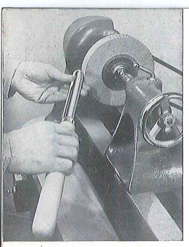
Sharpening • TURNING CHISELS
GENERAL NOTES TURNING chisels are usually made from a select grade of high-carcarbon steel with yanadium added
carbon steel with vandatum added for toughness. They should be ground with a 70-grit wheel of medium hardness, the wheel being dry but the tool dipped frequently in water to prevent burning. The grinding operation is conveniently done on the lathe at a 2400 r.p.m. speed with six or seven inch diameter wheel. Bevels of all chisels should be maintained at the approximate angles given in drawing below. All bevels must be straight or very slightly convex. Hollow grinding must be avoided when grinding turning chisels since this type of grind destroys the fulcrum action of the bevel.
Always use some kind of goggles (preferably safety goggles) in grinding to protect your eyes from flying grit.
THE GOUGE THE dest method of sharpening the gouge is shown in top photo. The chisel is rotated away from
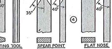
the operator. The bevel is visible at all times, making it easy to get a clean cut while maintaining the original bevel. The slight burr turned over on the inside of chisel can be removed with the use of a tapered wooden spindle covered with No. 3 (180-grit) emery cloth, as shown in Fig. 1. Another method uses a round slip stone, as in Fig. 2.
THE A PRECISION method of grinding SKEW the skew is shown in Fig. 3, where the chisel is cocked at an angle in the slide rest tool post and then fed into the side of the wheel. Care should be used in making the set-up to maintain the original bevel. Lacking the slide rest, the same operation can be done freehand, resting the chisel
on the wood turning tool rest. OTHER OTHER turning chisels present no CHISELS great difficulties in sharpening. The point of the parting tool must come exactly at the center where the chisel is thick-
1/16 5/64 3/32 7/64 1/8 9/64 5/32
W
6 to
8 to
FEE
FOR
Copper-Copper-
exactly at the center where the chisel is thickest. The spear point is sharpened on the side of the grinding wheel, much the same as the skew. The round nose chisel is rolled very much like the gouge. In all cases, touch-up sharpening by honing on a flat stone should come three or four times between grindings.


el is visible at all times, et α clean cut while l bevel. The slight burr uside of chisel can be of α tapered wooden No. 3 (180-grit) emery g. l. Another method e, as in Fig. 2.
N method of grinding shown in Fig. 3, where cocked at an angle in and then fed into the are should be used in maintain the original e rest, the same operatand, resting the chisel tool rest.
ng chisels present no ties in sharpening. The parting tool must come here the chisel is thicksharpened on the side much the same as the is chisel is rolled very In all cases, touch-up on a flat stone should tes between grindings.

TABLES
| DECIMAL E | QUIVALENTS | ||
|---|---|---|---|
|
1/64 = .015625
1/32 = .03125 3/64 = .046875 |
1/4 = .250
17/64 = .265625 9/32 = .28125 19/64 = .296875 |
1/2 = .500
33/64 = .515625 17/32 = .53125 35/64 = .546875 |
3/4 = .750
49/64 = .765625 25/32 = .78125 51/64 = .796875 |
| 1/16 == .0625 | 5/16 = .3125 | 9/16 = .5626 | 13/16 = .8125 |
| 5/64 == .078125 | 21/64 = .328125 | 37/64 = .578125 | 53/64 = .828125 |
| 3/32 == .09375 | 11/32 = .34375 | 19/32 = .59375 | 27/32 = .84375 |
| 7/64 == .109375 | 23/64 = .359375 | 39/64 = .609375 | 55/64 = .859375 |
| 1/8 = .125 | 3/8 = .375 | 5/8 = .625 | 7/8 = .875 |
| 9/64 = .140625 | 25/64 = .390625 | 41/64 = .640625 | 57/64 = .890625 |
| 5/32 = .15625 | 13/32 = .40625 | 21/32 = .65625 | 29/32 = .90625 |
| 11/64 = .171875 | 27/64 = .421875 | 43/64 = .671875 | 59/64 = .921875 |
| 3/16 = .1875 | 7/16 = .4375 | 11/16 = .6875 | 15/16 = .9375 |
| 13/64 = .203125 | 29/64 = .453125 | 45/64 = .703125 | 61/64 = .953125 |
| 7/32 = .21875 | 15/32 = .46875 | 23/32 = .71875 | 31/32 = .96875 |
| 15/64 = .234375 | 31/64 = .484375 | 47/64 = .734374 | 63/64 = .984375 |
|
Work
Diameter |
Roughing
Cuts |
Pulley
Step |
General
Cutting |
Pulley
Step |
Finish Cuts
and Sanding |
Pulley
Step |
|---|---|---|---|---|---|---|
| Up to 2-In. | 2300 | 3 | 2300 | 3 | 4300 | 1 |
| 2 to 3-In. | 1300 | 2 | 1300 | 2 | 2300 | 3 |
| 3 to 4-In. | 700 | 1 | 1300 | 2 | 2300 | 3 |
| 4 to 5-In. | 700 | 1 | 1300 | 2 | 1300 | 2 |
| 5 to 6-In. | 700 | 1 | 700 | Ĩ | 1300 | 2 |
| 6 to 7-In. | 700 | 1 | 700 | l î | 1300 | 2 |
| 7 to 8.In. | 700 | 1 | 700 | 1 | 700 | 1 |
| 8 to 9-In. | 700 | 1 | 700 | 1 î | 700 | 1 |
| 9 to 10-In. | 700 | 1 | 700 | î | 700 | 1 |
| Material | Rough Cut | Finish Cut |
|---|---|---|
| Aluminum | 200 | 300 |
| Bakelite | 100 | 140 |
| Brass—Soft | 140 | 200 |
| Bronze | . 80 | 100 |
| Copper—Soft | 140 | 200 |
| Copper—Hard | 80 | 140 |
| fiber | 80 | 140 |
| ormica, Micarta | 200 | 200 |
| ron—Cast | 60 | 100 |
| Rubber-Hard | 120 | 140 |
| Steel—Cast | 60 | 80 |
| Steel-Cold Rolled | 80 | 140 |
| steel—Tool | 60 | 120 |
| oteel—Machine | 80 | 140 |
| Trattord (All Cast | ||
| Plastics) | 300 | 500 |
| FEET PER MINUTE | ||||||
|---|---|---|---|---|---|---|
| Work | 60 | 80 | 100 | 120 | 140 | 200 |
| Revs. per Minute | ||||||
|
14 In.
14 In. 14 In. 14 In. 14 In. 14 In. 14 In. 14 In. 24 In. 24 In. 34 In. 34 In. 56 In. |
916
458 306 230 183 152 131 114 92 76 66 58 46 |
1222
611 407 306 244 204 175 153 122 102 88 76 62 |
1528
764 598 382 306 254 218 192 152 128 110 96 76 |
1833
917 611 458 367 306 262 229 183 154 132 115 91 |
2139
1070 713 535 428 357 306 267 213 179 154 134 107 |
3056
1528 016 764 612 508 436 384 304 256 220 192 152 |
| Divisions | Number of | Degrees | |
|---|---|---|---|
| Required | Spaces | of Arc | |
| 1 - | 60 | 360 | |
| 2 | 30 . | 180 | |
| 3 | 20 | 120 | |
| 4 | 15 | 90 | |
| 5 | 12 | 72 | |
| 6 | . 10 | 60 | |
| 10 | 6 | 36 | |
| 12 | 5 | 30 | |
| 15 | 4 | 24 | |
| 20 | 3 | 18 | |
| 30 | 2 | 12 | |
| 60 | 1 | 6 | |
| MATERIĂL |
Front
Clearance |
Side
Clearance |
Back
Rake |
Side
Rake |
|
|---|---|---|---|---|---|
| LUMINUM | 8° | 12° | 35° | 15° | |
|
BRASS AND SOFT
COPPER ALLOYS |
8° | 10° | 0° | 0° | |
| BRONZE | 8° | 10° | 0° | 2° | |
| CAST IRON | 8° | 10° | 5° | 10° | |
| COPPER (Pure) | 12° | 14° | 15° | 20° | |
| COPPER (Hard Alloys) | 12° | 10° | 10° | 2° | |
| IBER | 12° | 15° | 0° | 0° | |
| LASTIC (Cast) | 10° | 15° | ٥° | 0° | |
| UBBER (Hard) | 15° | 20° | 0° | 0° | |
| TEEL (Machine) | 8° | 12° | 15° | · 20° | |
| TEEL (Tool) | 8° | 10° | 8° | 12° | |
| Thread | Tap | Outside | Threads | Tap | Tap Drill | FC | JK TAPI | ikə |
|---|---|---|---|---|---|---|---|---|
| Series | Size | Diameter | per inch | Drill | Decimais |
Paper
per Inch |
Taper
per Foot |
Compound
Angle |
| -% crows. | 1/4-20 | .250 | 20 | .201 | 0104 | 14 | 0.010/ | |
| %−18 | .312 | 18 | F | .257 | 0156 |
78
3/ |
0.10 | |
| 3/8-16 | .375 | 16 | 5/16 | .312 | 0208 | 716 | 0°26' | |
| d S | ⅔-14 | .437 | 14 | U | .368 | 0260 |
74
5/. |
0.45 |
| hree | 1/2-13 | .500 | 13 | 27/64 | .422 | .0200 | ∕16 | 0 40 |
| Stan | %-12 | .562 | 12 | 31/64 | .484 | .0313 | 3/8 | 0°54′. |
| S. | 5/8-11 | .625 | 11 | 17/32 | .531 | .0365 | 7/16 | 1° 3′ |
| HUP. | 3/-10 | 750 | 10 | 21/32 | .656 | .0417 | 1/2 | 1°12′ |
| 74 10 | 21/02 | .0469 | 9/16 | 1°20′ | ||||
| ŝ | 1/4-28 | .250 | 28 | 3 | .213 | |||
|
10 5%-24
10 0(1.4.7) 10 0(1.4.7) 10 0(1.4.7) 10 0(1.4.7) 10 0(1.4.7) 10 0(1.4.7) 10 0(1.4.7) 10 0(1.4.7) 10 0(1.4.7) 10 0(1.4.7) 10 0(1.4.7) 10 0(1.4.7) 10 0(1.4.7) 10 0(1.4.7) 10 0(1.4.7) 10 0(1.4.7) 10 0(1.4.7) 10 0(1.4.7) 10 0(1.4.7) 10 0(1.4.7) 10 0(1.4.7) 10 0(1.4.7) 10 0(1.4.7) 10 0(1.4.7) 10 0(1.4.7) 10 0(1.4.7) 10 0(1.4.7) 10 0(1.4.7) 10 0(1.4.7) 10 0(1.4.7) 10 0(1.4.7) 10 0(1.4.7) 10 0(1.4.7) 10 0(1.4.7) 10 0(1.4.7) 10 0(1.4.7) 10 0(1.4.7) 10 0(1.4.7) 10 0(1.4.7) 10 0(1.4.7) 10 0(1.4.7) 10 0(1.4.7) 10 0(1.4.7) 10 0(1.4.7) 10 0(1.4.7) 10 0(1.4.7) 10 0(1.4.7) 10 0(1.4.7) 10 0(1.4.7) 10 0(1.4.7) 10 0(1.4.7) 10 0(1.4.7) 10 0(1.4.7) 10 0(1.4.7) 10 0(1.4.7) 10 0(1.4.7) 10 0(1.4.7) 10 0(1.4.7) 10 0(1.4.7) 10 0(1.4.7) 10 0(1.4.7) 10 0(1.4.7) 10 0(1.4.7) 10 0(1.4.7) 10 0(1.4.7) 10 0(1.4.7) 10 0(1.4.7) 10 0(1.4.7) 10 0(1.4.7) 10 0(1.4.7) 10 0(1.4.7) 10 0(1.4.7) 10 0(1.4.7) 10 0(1.4.7) 10 0(1.4.7) 10 0(1.4.7) 10 0(1.4.7) 10 0(1.4.7) 10 0(1.4.7) 10 0(1.4.7) 10 0(1.4.7) 10 0(1.4.7) 10 0(1.4.7) 10 0(1.4.7) 10 0(1.4.7) 10 0(1.4.7) 10 0(1.4.7) 10 0(1.4.7) 10 0(1.4.7) 10 0(1.4.7) 10 0(1.4.7) 10 0(1.4.7) 10 0(1.4.7) 10 0(1.4.7) 10 0(1.4.7) 10 0(1.4.7) 10 0(1.4.7) 10 0(1.4.7) 10 0(1.4.7) 10 0(1.4.7) 10 0(1.4.7) 10 0(1.4.7) 10 0(1.4.7) 10 0(1.4.7) 10 0(1.4.7) 10 0(1.4.7) 10 0(1.4.7) 10 0(1.4.7) 10 0(1.4.7) 10 0(1.4.7) 10 0(1.4.7) 10 0(1.4.7) 10 0(1.4.7) 10 0(1.4.7) 10 0(1.4.7) 10 0(1.4.7) 10 0(1.4.7) 10 0(1.4.7) 10 0(1.4.7) 10 0(1.4.7) 10 0(1.4.7) 10 0(1.4.7) 10 0(1.4.7) 10 0(1.4.7) 10 0(1.4.7) 10 0(1.4.7) 10 0(1.4.7) 10 0(1.4.7) 10 0(1.4.7) 10 0(1.4.7) 10 0(1.4.7) 10 0(1.4.7) 10 0(1.4.7) 10 0(1.4.7) 10 0(1.4.7) 10 0(1.4.7) 10 0(1.4.7) 10 0(1.4.7) 10 0(1.4.7) 10 0(1.4.7) 10 0(1.4.7) 10 0(1.4.7) 10 0(1.4.7) 10 0(1.4.7) 10 0(1.4.7) 10 0(1.4.7) 10 0(1.4.7) 10 0(1.4.7) 10 0(1.4.7) 10 0(1.4.7) 10 0(1.4.7) 10 0(1.4.7) 10 0(1.4.7) 10 0(1.4.7) 10 0(1.4.7) 10 0(1.4.7) 10 0(1.4 |
.312 | 24 | I | .272 | .0521 | 5/8 | 1°30′ | |
| 3/8-24 | .375 | 24 | Q | .332 | .0573 | 11/16 | 1°38′ | |
| ‰−20 | .437 | 20 | 25/64 | .390 | .0625 | 3/4 | 1.47 | |
| and | 1/2-20 | .500 | 20 | 29/64 | .453 | .0077 | 13/16 | 1-20, |
| Thr | %-18 | .562 | 18 | 33/64 | .515 | .0729 | 2/8 | 2° 5′ |
| A.E | $/8-18 | .625 | 18 | 37/64 | .578 | .0781 | 15/16 | 2°14′ |
| AH N | 34-16 | .750 | 16 | 11/16 | .687 | .0833 | 1 | 2°23′ |
| 3 | 4-40 | .1.12 | 40 | 43 | .089 | .1047 | 1 1/4 | 2°59′ |
| E C | 4-40 | .112 | 40 | 42 | .055 | .1250 | 11/2 | 3°34′ |
| lar | 5-40 | .125 | 40 | 37 | .101 | .1458 | 13/4 | 4°10′ |
| occi | 6-32 | .138 | 32 | 36 | .106 | .1667 | 2 | 4°45′ |
| ats . | 6-40 | .138 | 40 | 33 | .113 | .2083 | 21/2 | 5°57′ |
| M.E. |
8–32
8–36 |
.164 |
32
36 |
29
29 |
.136 | 0.000 | 0 | D0 , D 1 |
| Thr | 10-24 | 190 | 24 | 25 | 149 | .2500 | 3 | |
| C.MO | 10-32 | .190 | 32 | 21 | .159 | .2917 | 31/2 | 0000/ |
| 14 6 | 12 24 | 216 | 24 | 16 | 177 | .3333 | 4 | 9 20 |
• ILLUSTRATIONS in this book picture the CRAFTSMAN lo-inch Wood Lathe. The working methods described can be applied generally to any CRAFTSMAN, COMPANION or other wood lathe. Accessories shown are standard items in Sears complete line of power tools.


 Loading...