

INDEX
| PORING (with Dealers Deal | - |
|---|---|
| BORING (WITH BOFING BAF) | 14 |
| BORING IN WOOD | -10 |
| Bits_Speeds_Boring to Depth | The Par |
| -Tilting Table-Use of Pivot- | |
| Holes in Series—Deep Holes— | |
| End Boring — Large Holes— | |
| Counterboring — Screw Holes | |
| BUFFING AND POLISHING | 27 |
| CARVING | 27 |
| 14 | |
| 25 | |
| 25 | |
| DOVETAILING | -17 |
| Jig — Clamping — Setting | |
| Guides — Cutting — Lipped | |
| Drawers | |
| DOVETAIL GROOVING | 22 |
| DRIFTING A HOLE | 11 |
| DRILLING IN METAL11 | -14 |
| Drills — Speed — Drifting a | |
| Hole — Holding Work — Lubri- | |
| cants — Drill Vise — Milling | |
| Vise—Countersinking — Ream- | |
| ing — Boring — Lapping — | |
| Tapping | - |
| DRILLING GLASS | 25 |
| ELECTRIC DRILLS | 30 |
| FLUTING | 26 |
| GRINDING | 28 |
| KEYWAYS (Cutting) | 27 |
| APPING | 14 |
| AYING OUT HOLES A | 5 |
| 27 | |
| 21 | |
| 20 | |
| MORTISING | 18 |
| MORTISING (With Router Bits) | 22 |
| MORTISING (With Router Bits) PLUGS (Cutting) |
22
25 |
|
MORTISING (With Router Bits)
PLUGS (Cutting) REAMING |
22
25 14 |
|
MORTISING (With Router Bits)
PLUGS (Cutting) REAMING ROSETTES (Cutting) |
22
25 14 25 |
|
MORTISING (With Router Bits)
PLUGS (Cutting) REAMING ROSETTES (Cutting) |
22
25 14 25 -23 |
|
MORTISING (With Router Bits)
PLUGS (Cutting) REAMING ROSETTES (Cutting) ROUTING |
22
25 14 25 -23 |
|
MORTISING (With Router Bits)
PLUGS (Cutting) REAMING ROSETTES (Cutting) ROUTING |
22
25 14 25 -23 |
|
MORTISING (With Router Bits)
PLUGS (Cutting) REAMING ROSETTES (Cutting) |
22
25 14 25 -23 |
|
MORTISING (With Router Bits)
PLUGS (Cutting) REAMING ROSETTES (Cutting) |
22
25 14 25 -23 |
|
MORTISING (With Router Bits)
PLUGS (Cutting) REAMING ROSETTES (Cutting) |
22
25 14 25 -23 |
|
MORTISING (With Router Bits)
PLUGS (Cutting) REAMING ROSETTES (Cutting) ROUTING Grooves — Rabbeting — Ir- regular Curves—Using Pivot— Cross Routing — Dovetail Grooving — Mortising — Routing with Pattern SANDING |
22
25 14 25 -23 24 |
|
MORTISING (With Router Bits)
PLUGS (Cutting) REAMING ROSETTES (Cutting) ROUTING Grooves — Rabbeting — Ir- regular Curves—Using Pivot— Cross Routing — Dovetail Grooving — Mortising — Routing with Pattern SANDING SHAPING |
22
25 14 25 -23 24 20 |
|
MORTISING (With Router Bits)
PLUGS (Cutting) REAMING ROSETTES (Cutting) ROUTING Grooves — Rabbeting — Ir- regular Curves—Using Pivot— Cross Routing — Dovetail Grooving — Mortising — Routing with Pattern SANDING SHAPING Setting Up—Feed—With Fence |
22
25 14 25 -23 24 20 |
|
MORTISING (With Router Bits)
PLUGS (Cutting) REAMING ROSETTES (Cutting) ROUTING Grooves — Rabbeting — Ir- regular Curves—Using Pivot— Cross Routing — Dovetail Grooving — Mortising — Routing with Pattern SANDING SHAPING Setting Up—Feed—With Fence — With Collars — With Pattern |
22
25 14 25 -23 24 20 |
|
MORTISING (With Router Bits)
PLUGS (Cutting) REAMING ROSETTES (Cutting) ROUTING Grooves — Rabbeting — Ir- regular Curves—Using Pivot— Cross Routing — Dovetail Grooving — Mortising — Routing with Pattern SANDING SHAPING Setting Up—Feed—With Fence — With Collars — With Pattern SHARPENING SHAPENING SHARPENING SHARPENING SHARPENING SHARPENING SHARPENING SHARPENING SHARPENING SHARPENING SHARPENING SHARPENING SHARPENING SHARPENING SHARPENING SHARPENING SHARPENING SHARPENING SHARPENING SHARPENING SHARPENING SHARPENING SHARPENING SHARPENING SHARPENING SHARPENING SHARPENING SHARPENING SHARPENING SHARPENING SHARPENING SHARPENING SHARPENING SHARPENING SHARPENING SHARPENING SHARPENING SHARPENING SHARPENING SHARPENING SHARPENING SHARPENING SHARPENING SHARPENING SHARPENING SHARPENING SHARPENING SHARPENING SHARPENING SHARPENING SHARPENING SHARPENING SHARPENING SHARPENING SHARPENING SHARPENING SHARPENING SHARPENING SHARPENING SHARPENING SHARPENING SHARPENING SHARPENING SHARPENING SHARPENING SHARPENING SHARPENING SHARPENING SHARPENING SHARPENING SHARPENING SHARPENING SHARPENING SHARPENING SHARPENING SHARPENING SHARPENING SHARPENING SHARPENING SHARPENING SHARPENING SHARPENING SHARPENING SHARPENING SHARPENING SHARPENING SHARPENING SHARPENING SHARPENING SHARPENING SHARPENING SHARPENING SHARPENING SHARPENING SHARPENING SHARPENING SHARPENING SHARPENING SHARPENING SHARPENING SHARPENING SHARPENING SHARPENING SHARPENING SHARPENING SHARPENING SHARPENING SHARPENING SHARPENING SHARPENING SHARPENING SHARPENING SHARPENING SHARPENING SHARPENING SHARPENING SHARPENING SHARPENING SHARPENING SHARPENING SHARPENING SHARPENING SHARPENING SHARPENING SHARPENING SHARPENING SHARPENING SHARPENING SHARPENING SHARPENING SHARPENING SHARPENING SHARPENING SHARPENING SHARPENING SHARPENING SHARPENING SHARPENING SHARPENING SHARPENING SHARPENING SHARPENING SHARPENING SHARPENING SHARPENING SHARPENING SHARP |
22
25 14 25 -23 24 20 29 |
|
MORTISING (With Router Bits)
PLUGS (Cutting) REAMING ROSETTES (Cutting) ROUTING Cross Cutting - Ir- regular Curves-Using Pivot- Cross Routing - Dovetail Grooving - Mortising - Routing with Pattern SANDING SHAPING Staping Up-Feed-With Fence - With Collars - With Pattern SHARPENING Drill Grinding - Thinning Web |
22
25 14 25 -23 24 20 29 |
|
MORTISING (With Router Bits)
PLUGS (Cutting) REAMING ROSETTES (Cutting) ROUTING Grooves — Rabbeting — Ir- regular Curves—Using Pivot— Cross Routing — Dovetail Grooving — Mortising — Routing with Pattern SANDING SHAPING SHAPING SHARPENING Dill Grinding — Thinning Web —Drill for Brass—Wood Bits— |
22
25 14 25 -23 24 20 29 |
| MORTISING (With Router Bits) PLUGS (Cutting) REAMING ROSETTES (Cutting) ROUTING ROUTING Tegular Curves—Using Pivot— Cross Routing — Dovetail Grooves in g — Mortising — Routing with Pattern SANDING Setting Up—Feed—With Fence — With Collars — With Pattern SHARPENING SHARPENING Drill Grinding — Thinning Web Drill for Brass—Wood Bits— Router Bits—Mortising Chisels |
22
25 14 25 -23 24 20 29 |
| MORTISING (With Router Bits) PLUGS (Cutting) REAMING ROSETTES (Cutting) ROUTING ROUTING Tegular Curves—Using Pivot— Cross Routing — Dovetail Grooves — Rabbeting — Ir- regular Curves—Using Pivot— Cross Routing — Dovetail Grooving — Mortising — Routing with Pattern SANDING Stating Up—Feed—With Fence With Collars — With Pattern SHAPENING Drill Grinding — Thinning Web —Drill for Brass—Wood Bits— Router Bits—Mortising Chisels —Shaper Cutters |
22
25 14 25 -23 24 20 , 29 |
| MORTISING (With Router Bits) PLUGS (Cutting) REAMING ROSETTES (Cutting) ROUTING ROUTING Tegular Curves—Using Pivot— Cross Routing — Dovetail Grooves — Rabbeting — Ir- regular Curves—Using Pivot— Cross Routing — Dovetail Grooving — Mortising — Routing with Pattern SANDING Stating Up—Feed—With Fence With Collars — With Pattern ShapenNing |
22
25 14 25 -23 24 20 29 29 |
| MORTISING (With Router Bits) PLUGS (Cutting) REAMING ROSETTES (Cutting) ROUTING ROUTING Tegular Curves—Using Pivot— Cross Routing — Dovetail Grooves — Rabbeting — Ir- regular Curves—Using Pivot— Cross Routing — Dovetail Grooving — Mortising — Routing with Pattern SANDING Stating Up—Feed—With Fence With Collars — With Pattern ShapenNing |
22
25 14 25 -23 24 20 .29 25 24 2 |
| MORTISING (With Router Bits) PLUGS (Cutting) REAMING ROSETTES (Cutting) ROSETTES (Cutting) ROUTING ROUTING Grooves Rabbeting If Grooves Routing Do vetail Grooving Do vetail Grooving Mortising Routing with Pattern SANDING Stang Up—Feed—With Fence With Collars With Collars Setting Up—Feed—With Fence With Collars Drill Grinding Thinning Web Drill for Brass Wood Bits Router Bits Shaper Cutters SPINNING RIVETS SPOT FINISHING SURFACE GRINDING |
22
25 14 25 -23 24 20 29 25 24 27 |
|
MORTISING (With Router Bits)
PLUGS (Cutting) REAMING ROSETTES (Cutting) ROUTING ROUTING Grooves — Rabbeting — Ir- regular Curves—Using Pivot— Cross Routing — Dovetail Grooving — Mortising — Routing with Pattern SANDING SHAPING SHAPING Setting Up—Feed—With Fence — With Collars — With Pattern SHARPENING Drill Grinding — Thinning Web —Drill for Brass—Wood Bits— Router Bits—Mortising Chisels —Shaper Cutters SPINNING RIVETS SPOT FINISHING SURFACE GRINDING - 21 |
22
25 14 25 -23 24 20 , 29 25 24 27 27 22 |
|
MORTISING (With Router Bits)
PLUGS (Cutting)
REAMING
ROSETTES (Cutting)
ROUTING
ROUTING
Cross Routing — Ir-
regular Curves—Using Pivot— Cross Routing — Dovetail Groover and the statem Sanding With Pattern SANDING Setting Up—Feed—With Fence — With Collars — With Pattern Shapen Cutters Drill Grinding — Thinning Web —Drill for Brass—Wood Bits— Router Bits—Mortising Chisels —Shaper Cutters SPINNING RIVETS Spot FINISHING Surface GRINDING TABLES 31 |
22
25 14 25 -23 24 20 , 29 25 24 27 , 32 |
|
MORTISING (With Router Bits)
PLUGS (Cutting)
REAMING
ROSETTES (Cutting)
ROUTING
ROUTING
Grooves — Rabbeting — Ir-
regular Curves—Using Pivot— Cross Routing — Dovetail Grooving — Dovetail Grooving — Mortising — Routing with Pattern SANDING SHAPING Setting Up—Feed—With Fence — With Collars — With Pattern SHARPENING 28 Drill Grinding — Thinning Web —Drill for Brass—Wood Bits— Router Bits—Mortising Chisels —Shaper Cutters SPINNING RIVETS Spot FINISHING SURFACE GRINDING 31 Decimal Equivalents—Number |
22
25 14 25 -23 24 20 29 25 24 27 32 |
| MORTISING (With Router Bits) PLUGS (Cutting) REAMING ROSETTES (Cutting) ROUTING ROUTING Tegular Curves—Using Pivot— Cross Routing — Dovetail Grooves — Rabbeting — Ir- regular Curves—Using Pivot— Cross Routing — Dovetail Grooving — Mortising — Routing with Pattern SANDING Stanping Up—Feed—With Fence — With Collars — With Pattern SHARPENING Sharen Mortising Chisels —Drill Grinding — Thinning Web —Drill for Brass—Wood Bits— Router Bits—Mortising Chisels —Shaper Cutters SPINNING RIVETS SPOT FINISHING SURFACE GRINDING TABLES — Drills-Letter Drills—Lubricants — Drills for Wood Screws |
22
25 14 25 -23 24 20 29 225 24 27 32 |
| MORTISING (With Router Bits) PLUGS (Cutting) REAMING ROSETTES (Cutting) ROUTING ROUTING Tegular Curves—Using Pivot— Cross Routing — Dovet ail Grooves — Rabbeting — Ir- regular Curves—Using Pivot— Cross Routing — Dovet ail Grooving — Mortising — Routing with Pattern SANDING Stting Up—Feed—With Fence — With Collars — With Pattern SHARPENING Shaper Substanting Web —Drill for Brass—Wood Bits— Router Bits—Mortising Chisels —Shaper Cutters SPINNING RIVETS SPOT FINISHING SURFACE GRINDING TABLES — Drills—Letter Drills—Lubricants — Drills for Wood Screws — Drill Speeds |
22
25 14 25 -23 24 20 29 25 24 27 , 32 |
| MORTISING (With Router Bits) PLUGS (Cutting) REAMING ROSETTES (Cutting) ROUTING ROUTING Tegular Curves—Using Pivot— Cross Routing — Dovetail Grooves — Rabbeting — Ir- regular Curves—Using Pivot— Cross Routing — Dovetail Grooving — Mortising — Routing with Pattern SANDING SHAPING Stting Up—Feed—With Fence With Collars — With Pattern SHAPENING Shapen Cutters Spont fining — Thinning Web —Drill for Brass—Wood Bits— Router Bits—Mortising Chisels —Shaper Cutters SPOT FINISHING SURFACE GRINDING TABLES 31 Decimal Equivalents—Number Drills for Wood Screws — Drill Speeds |
22
25 14 25 -23 24 20 29 25 24 27 , 32 |

The DRILL PRESS
A MANUAL FOR THE HOME CRAFTSMAN AND SHOP OWNER
Over 100 Drill Press Operations Described and Illustrated
A CRAFTSMAN Power Tool Handbook
Copyright 1940 SEARS ROEBUCK AND CO. CHICAGO
The second
Catalog No. 9-2921
Printed in U.S.A.

The DRILL PRESS
CONSTRUCTION THE drill press is a vertical spindle which can be moved up and down by means of
a feed lever. The upper end of the spindle transmits the drive, while the lower end is tapered or threaded to take various chucks. The complete unit comprising the spindle and the housing which carries it is called the head The head is mounted on a steel column and can be moved up or down. The table is mounted on the column below the head. and can be moved up. down or sideways. On many drill presses, the table can also be tilted Adjustments are provided for belt tension, spindle return and depth of cut. The size o the machine is usually expressed in terms of the largest circle which can be center-drilled. For example, a drill press which can drill in the center of a 15 inch diameter disk is called
MOTOR A 15-inch drill press is commonly fitted with a 1/3 h. p., 1750 r. p. m. motor, and this power is sufficient for all average work. Where the machine is used for production work, or where a multi-speed countershaft is used, a 1/2 h. p. motor is recommended.
The motor is generally fitted with a four-step cone pulley, giving a speed range approximately 600, 1,300, 2,450 and 5,200 r. p. m. A multi-speed countershaft gives a range of twenty speeds from 200 to 10,000 r. p. m.
AUXILIARY THE spindle of the drill press terminates in either a straight threaded shank or a Morse CHUCKS taper shank without threads. The standard chuck fitted to the shank of the spindle is usually a 1/2 inch adjustable chuck, either keyless or geared Jacobs chuck. Many styles of auxiliary chucks are available, and are fitted with either threaded hole or tapered hole to fit the spindle of the machine. Where the spindle is a threaded shank, auxiliary chucks are simply screwed in place; where the spindle is a tapered shank, all types of auxiliary chucks are fitted with a flange at the upper end so that the chuck can be positively locked to the spindle by means of a knurled collar. The collar is tightened by the fingers while the spindle is held stationary by holding the belt or by means of a drift key fitting through the chuck. as shown in the upper photo. The same procedure loosens the ring, after which the chuck can be removed by driving the drift key completely through the hole to pry it loose from the tapered shank of the spindle. The Jacobs chuck is the only type not fitted with flange. This chuck is secured only by the wedging action of the taper shank, which grips tighter as end pressure is increased. The knurled collar is in place on the lower end of the spindle, but is not used to secure the lacobs chuck. The chuck is removed by inserting a double prong drift key between it and the collar and striking a few light blows with a hammer. ADJUSTING LARGER drill presses are fitted with an ad-
ADJUSTING QUILL RETURN LARGER drill presses are litted with an adjustable quill return. Tension is increased by turning the spring housing counter clockwise. To release the tension, pull up
on the small ratchet knob, as shown in Fig. 2, and let the housing turn back to where desired.

Auxiliary chucks are secured to the tapered shank of main spindle by means of a knurled collar.

(1) Removing Jacobs chuck. (2) Adjusting quill return. (3) Belt tension.

Laying Out • HOLES
COMMON BEFORE any hole can be drilled, PRACTICE it is usually necessary to make some kind of mark to indicate its location. Layout work of this kind ranges all the way from very rough work done with the simplest kind of tools to precise markings employing the finest of measuring instruments. In the homeshop, such standard tools as the combination square, dividers and calipers can be used for most work. A typical use of the combination square is shown in Fig. 1 where lines set off from each side of the work locate the approximate centerline.
Fig. 2 illustrates the same method applied in locating the center of a square piece of work. The second diagram in Fig. 2 shows the familiar method of locating the center of square work by means of diagonals. Fig. 3 shows the centerhead of the combination square being used to locate the center of a round piece of work. Providing the work is truly round, any two lines drawn on it with the use of the centerhead will intersect in the exact center.
A typical example of the use of hermaphrodite calipers is shown in Fig. 4. This style of caliper has one bent leg which can be hooked over the edge of the work or the end of a steel rule. The other leg is fitted with a scriber. The location of any point in relation to other points can be set off most accurately with the use of dividers, as shown in Fig. 5.
DOWEL PRECISE layout work is required when laying out dowel holes. Where the work is an edge-to-edge joint
using several pieces of wood, the method shown in Fig. 1 on the opposite page can be used to good advantage. The various pieces of work are first squared up, after which lines are drawn at random across the edges, using the combination square as shown. In drilling the holes, a fence should be used on the drill table, so that, with the work against the fence the holes will be centered. The face side of each board should be marked and all faces kept one way when drilling. Fig. 3 illustrates the template method of marking dowel holes. A thin metal template with small holes drilled through it to show the location of the dowel holes is used. This is placed on first one piece of the work and then the other, the holes being marked with a scratch awl or other sharp point. For all ordinary dowel marking, double point pins or dowel pops can be used. In using dowel pops, the dowel holes are first drilled in one piece of the work. The pops are then inserted in these holes, after which the second piece of work is pressed against the first to locate the dowel holes in second piece. as shown in Fig. 4. Where double point pins are

The combination square, dividers and calipers are used extensively in laying out holes for drilling.

used, the pins are stuck in one part of the work and the second piece then pressed into contact. The pins should be very short in order to make perfect registering easy; long pins frequently show the work out-of-register when the two pieces are pushed together. For rough work, ordinary household pins can be used. The head is placed on one part of the work and the other part is then brought into contact, the head thus marking the dowel position on both parts.
USING SURFACE GAGE THE surface gage is an inexpensive instrument for fine layout work. A micrometer adjustment permits exact setting to the required dimension, as shown in Fig. 5, after which
the same dimension can be transferred to the work. Skilled mechanics use the surface gage for a wide variety of accurate layout work.
PUNCH LAYOUT work in metal employs a scriber in MARKS the same manner as a pencil is used on wood. The intersection of the scribed lines is then carefully marked with a center punch. Care should be exercised in using the punch to locate it exactly right. The punch should be held vertical, as shown in Fig. 6, since a slanting position can easily change the position of the hole. The automatic spring punch shown in Fig. 7 is frequently useful for delicate work. A spring action is used, the head being pulled up and let go to make the punch mark. Fig. 8 illustrates the layout used where great accuracy is required in drilling a hole. Besides the punch mark in center, two rings are scribed around the center with the use of the dividers, the outer ring being the exact size of the hole to be drilled. Small punch marks are placed at the intersection of the layout lines and the outer circle. When the hole is drilled, the inner scribed circle checks the accuracy of the drill at the start of the operation, while the outside punch marks give proof of accurate work. This method is only necessary, of course, when very exacting work is being done.
MARKING A PENCIL is invariably used for all layout marks on wood. For dull iron surfaces, soapstone can be used or the work can be coated with whiting or white shoe polish, as shown in Fig. 9. Soft metals such as aluminum and copper take scribed marks very nicely without any other treatment. Polished steel is too hard to be marked with the scriber. This and other hard metals should be coated with a solution of copper sulphate. The solution can be applied with a brush or cloth swab and builds up an ideal marking surface in a few minutes. A 20 per cent solution of silver nitrate can be used on hard copper and brass to produce a film coating which will show scribed lines clearly.
Above, various methods used in marking dowel holes. Lower photo shows use of surface gage.

Below, accurate punch marks are required when drilling holes in metals.


Boring in • WOOD
BORING VARIOUS styles of wood bits are used for boring holes on the drill press. The most effective point is the brad or diamond point, although some drill presses with controlled feed use the familiar screw point. For all boring in the homeshop, however, the brad point is much superior. As a matter of fact, a fast, coarse screw point cannot be used at all on the drill press with ordinary hand feed since the screw point will engage the work and lift it from the drill table. Where such bits are used on the drill press, the point should be filed to a brad point.
The drawing shows typical bits. At the top is the solid center bit. This has one flute or twist which turns about a solid center, and, from this solid center stem the bit gets its name. Although it has but one flute, a second cutting edge is brought out immediately behind the point, so that the bit has two cutting edges and two spurs. The hollow spiral or ship auger bit is used extensively for boring deep holes. It has but one cutting edge. The hollow space through the center permits passage of chips, a necessary feature of deep hole drilling. The fluted bit is a pattern familiar to almost every woodworker. It is an excellent all around boring bit having two twists which terminate in two cutting edges and two spurs. The ordinary twist drill used for metal work is frequently
used in wood, but should preferably be ground to a much sharper angle than is used for metal drilling. An included angle of 118 degrees is usually specified for metal drilling, while the same drill for wood should have an included angle of about 75 degrees. A spur machine bit in a twist drill pattern is perhaps the best type of general purpose drill for drilling wood. It is stiff, tracks nicely, and gives a perfectly smooth hole. One style of countersink bit is illustrated in the drawing. This has two cutting edges. The multi-spur bit pictured at the bottom of the drawing is one of several patterns of rim bits. It is excellent for large holes.
SPEEDS NO fixed table of drill speeds for boring in wood can be given since the best speed will vary with the bit pattern, the wood, grain, depth of hole, etc. Generally, bits up to ¾ inch diameter can be run between 1,800 to 3,000 r. p. m. Larger drills should be run at much lower speeds. A 1 inch fluted bit, for example, will burn if operated at 2,400 r. p. m. Bits over 1 inch generally take the lowest drilling speeds. Multi-spur and expansive bits overheat and burn at speeds over 750 r. p. m. In every case, the worker can determine the right speed by observing the work — when


Above, correct and incorrect methods of boring holes. Photos at right show standard drilling operations.
the drill smokes in the hole the speed should be reduced immediately to prevent burning.
BORING IN BORING holes through wood, the best prac- A HOLE tice is to place a scrap piece of wood under the work. Cutting through the work and into
the scrap, the bit will cut clean all the work and shown in Fig. 2. Unsupported work will always splinter as the drill breaks out on the lower side, as shown in Fig. 1. Another correct method of drilling which is sometimes useful is shown in Fig. 3, where the hole is drilled from both sides of the work. In all drilling, excessive feed pressure should be avoided. Do not try to burn a hole through the work with a dull drill. For a clean hole on the underside, the feed should be slowed up a bit as the drill breaks through.
BORING A PENCIL mark should be drawn upon the TO DEPTH outer surface of the work to show the exact depth to which the hole is to be drilled. The
depth to which the hole is to be drilled. The bit is brought down alongside this hole until the cutters are in line with the mark, at which point the quill is locked. The nuts on the feed stop stud are set to this position, as shown in Fig. 4, after which the quill can be released and the hole drilled. For rough boring to depth, the amount of travel required can be read direct from the scale on the feed stop stud.
TILTING BY LOOSENING the nut on the underside of TABLE the table and removing the lock pin, the table can be tilted to a vertical position facing either right or left. Holes are usually provided to take the lock pin at these positions. Other holes can be drilled by the operator if desired. Where a table angle other than level or vertical is required, the best method of working is to set the exact angle required on a set square and then tilt the table until the set square is in alignment with the drill, as shown in Fig. 5. In using a square in this manner on the drill table, care should be taken that the square is placed exactly across the table, not leading off to the back or front edges. To the same end, the work must be placed exactly across the table when boring the hole. Very often, the angle can be marked on the outer surface of the work, and the table is then set so that the drill lines up with the pencil mark.
USING A WHERE holes are to be drilled around the rim of a circular piece of work, a pivot pin can be used to advantage to secure the correct
spacing from the center. Another pin can be used to index the holes to secure the proper distance each one should be from the next. Fig. 6 shows the set-up. Simple jigs of this kind requiring guide holes should always be worked over a piece of scrap wood clamped to the auxiliary wood drill table.

7

Methods used in drilling round work. The centerline of work must be in line with center of drill.
DRILLING THE rule for drilling holes through round work is that the centerline of the work must be in line with the centerline of the drill. The
correct setting for any size of work is obtained by clamping a wooden vee block to the drill table in such a position that the point of the drill is in line with the bottom of the vee, as shown in Fig. 1. Any round piece of work drilled with the use of the vee block in this position will be automatically drilled exactly through the center, as in Fig. 2. Where a vee block is not used, accurate work can be done by centerlining the end of the work with the then placing the work on the drill table so that the centerline on the work is vertical and directly under the drill point, as shown in Fig. 3 Fairly accurate work can be done by eve A fence fitted to the drill table is an aid to good work since it not only insures greater accuracy but also prevents the work from rolling. Holes around the edge of a large circular piece of work can be bored by tilting the table vertical and resting the work on the heads of two bolts fitted through the slots in the drill table, as shown in Fig. 4. It can be seen that this arrangement is guite similar to a vee block. After the bolts have been properly set for the first hole, any other hole in the rim will automatically line up with the center.
HOLES IN WHERE holes are to be drilled in series a straightline series, each equally spaced from the next in line, simple jigs will speed the work and insure accuracy. A very simple method is to use spacing blocks, as shown in Fig. 5. One block at a time is removed until the entire series is drilled. This method has the advantage that it can be set up with different spacer blocks to drill a series of holes at irregular intervals along a straight line. Also, by using a long spacer block between the work and the fence,

Spacing blocks or a simple jig using an index pin are used for boring holes in series.
a second series of holes can be bored. A second method of drilling holes in series is shown in Fig. 6. This makes use of a spacer pin. In working, the first two holes are measured and drilled in the usual manner. The pin is then fixed so that when it is engaged in the first hole, the drill will be in the second hole. With the setting thus made, succeeding holes are accurately spaced, each hole serving as an index to the next in line. Fairly accurate work can be done without the pin by simply setting each hole to a pencil mark on the fence.
BORING ANY hole in wood over 3 inches is generally classed as a deep hole. Holes of this depth and up to about four inches are drilled in the conventional method. It is good practice to lift the
Ventional method. It is good product of the the bit once or twice to make certain that the hole is not fouled with chips. A distinct dividing line in deep hole drilling arises when the hole to be bored exceeds the length of the bit. In the usual standard size, the average bit for boring on the drill press will be about 4 inches long, which matches the 4 inch stroke of the average drill press. These bits can be made to cut about 5 inches deep by lifting the bit repeatedly to allow the chips to escape. Holes deeper than this must be worked from opposite ends of the work. A typical example is the boring of a hole through a cylinder, as shown in Fig. 1. In this case, the work is carefully aligned in a suitable vee block, after which boring from either end will generally result in satisfactory work.
Where the work can be supported on the drill table, the method illustrated in Figs. 2, 3
and 4 will insure good results. Using the bit which will later be used on the work. a hole is bored in a scrap piece of wood, Fig. 2. The drill table is then dropped the required distance to clear the work under the drill point. The drill is removed and a length of wood or metal rod is fixed in the chuck. Using this as a guide, the hole in the scrap block is lined up with the chuck, as shown in Fig. 3. and clamped to the drill table. The hole in the work is now drilled to the full capacity of the bit. A wood or metal guide pin is used to center the work for the drilling of the second hole, which is done from the opposite end of the work, Fig. 4.
Right, method of boring deep holes. Below, α support for end boring.


Above, drilling a hole in a cylinder. Below, using a raising block under the work in deep hole drilling.
Where the bit is long enough to go through the work but exceeds the feed stroke of the drill press, it is a simple matter to set up the work with a wood block or by raising the table so that the balance of the hole can be drilled. Fig. 7 illustrates the operation.
BORING SOMETIMES a fairly END deep but not a through hole must be drilled in the end of the work. The difficulty in this case arises in properly supporting the work. Where the piece is short, it can usually be clamped to the drill table which then

DRILL WORK FROM BOTH S
DRE HOLE IN SCRAP BL

Large holes can be bored by using an expansive bit with the threads filed off. A hole saw can be used on thin stock.
should be in a vertical position. Longer work can be worked with the use of the simple support shown in Fig. 5. This consists of a fence which slides on a bracket fitted to the drill column. An adjustment is provided to accommodate various sizes of work. The method of using the jig should be apparent, as shown in Fig. 6 on the previous page.
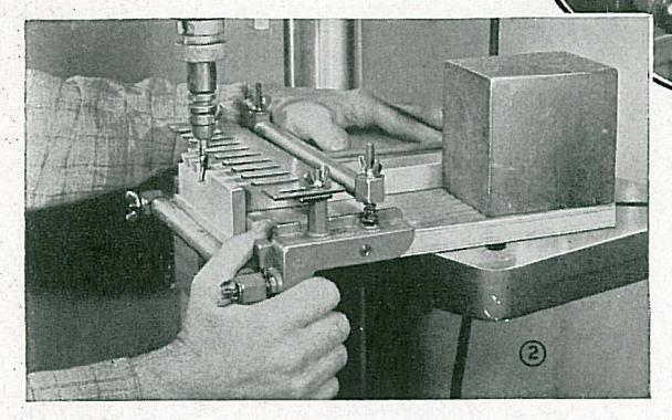
LARGE HOLES over 11/4 inches in diameter can gen-HOLES erally be classed as large holes. In most cases. bits over this size will not be available in the homeshop, and the best practice is to use an expansive bit. Best results are obtained if this is a type made especially for use on the drill press, but an ordinary expansive bit with screw point can be adapted by sawing off the shank and filing away a portion of the screw thread, as shown in Fig. 2. Since this type of cutter has but one cutting edge, it is necessary to clamp the work to the drill table, as shown in Fig. 1, otherwise the onesided action is liable to throw the work. Large holes in thin stock can also be cut with a hole saw, as shown in Fig. 3. This differs from the cutting action of a bit in that the bulk of the wood inside the hole is not removed.
COUNTER COUNTERBORING is the term applied to the BORING enlargement of the outer portion of a drilled hole. When worked with wood bits, the larger hole should be drilled first, as shown in Fig. 4, after which the smaller bit will center readily in the depression left by the larger bit. When the counterbore extends nearly through the work, a rim bit allows stronger construction, as can be seen in Fig. 5.
BORING WOOD to be fastened together by screws re- SCREW quires the boring of two holes for each screw. HOLES The outermost of the two holes accommodates the shank of the screw and is drilled entirely
through the first piece of stock, as shown in Fig. 6. The inner or anchor hole is drilled to a depth and diameter to take the screw being used. Anchor holes in end grain should be smaller than in side grain. Consult the table on page 32 for proper sizes of shank and anchor holes.

Careful boring of screw holes is necessarv for maximum holding strength
Drilling in ETAL
DRILLS THE term, "drill," is generally ap plied to the twist drill, and it is this
type which is used almost exclusively for metal drilling in the homeshop. The nomenclature of the twist drill is given in Fig. 1. The illustration shows a taper shank drill. The taper is generally No. 1 or No. 2 Morse. In order to use this style of drill on the drill press, it is necessary to use an adapter socket, such as is shown in Fig. 4. This adapter socket, in common with most auxiliary chucks, should be locked in place with the main spindle collar. Most homeshop work is done with straight shork twist drills. Fig. 2, any size of which up to 1/2 inch can be aripped in the lacobs chuck. Another type of drill which is used considerably on the drill press is the 60° countersink drill, as shown in Fig. 3. This drill is used for boring the centerholes in lathe work preparatory to mounting for turning.
The metal of which the drill is made is either carbon or high speed steel. Carbon steel drills are inexpensive and will give excellent
SPEED
A HOLE
results if operated at the proper speed. The more expensive high speed steel drills can be operated at twice the speed of carbon drills and will stay sharp much longer. Both carbon and high speed drills can be purchased in a wide variety of sizes, the size being indicated by a fraction or by a number or letter. See page 31.


When the drill is again started, it will drift to the approximate right position. Drifting a hole in this manner is a remedy but not a cure. If the drill wanders repeatedly, check carefully to determine the cause. On drills over 1/2 inch diameter, it is good practice to spot the hole with a smaller drill which will track more readily in the punch mark.
HOLDING WORK FOR DRILLING
IN DRILLING, the drill has a tendency to rotate the work. This can often be stopped by the hands alone, but the better
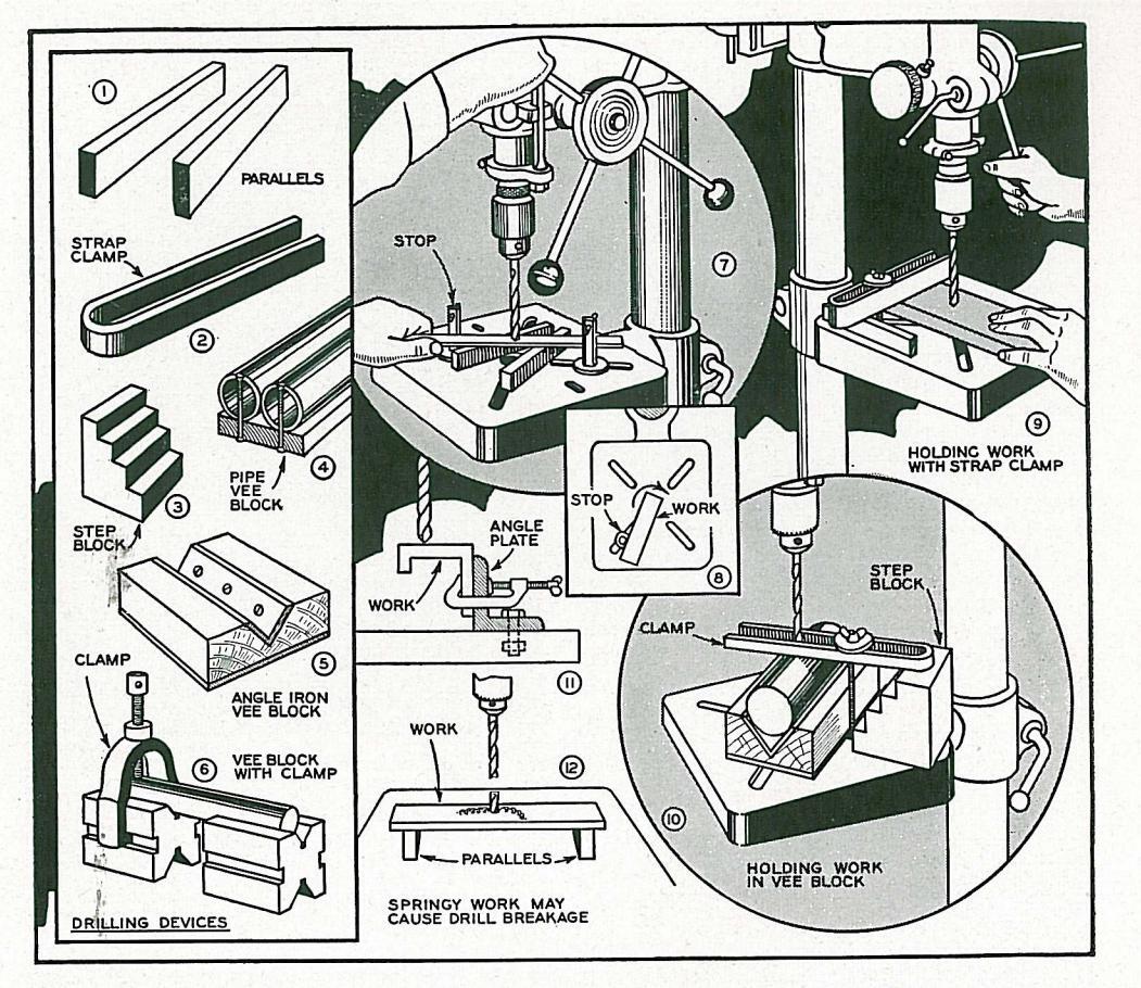
practice is to use some form of holding device. Work held by the hands alone sometimes gets away from the operator and may result in damage to the work or drill or injury to the operator. The simplest method of holding entails the use of a stop plate or a stop bolt. as shown in Figs. 7 and 8. Either one or two stons can be used and the stop itself can be a bolt a block of wood a clamp or any other device. Another common method of holding employs one or two strap clamps, as shown in Fig. 9. Clamps can be made from heavy strap iron bent to a U-shape, as shown in Fig. 2. Fig. 10 shows a strap clamp used in connection with a step block and vee block to hold a cylinder for drilling. Fig. 11 illustrates how
certain shapes can be clamped to an angle plate. Other devices can be worked out to suit the nature of the job. Three and fourjaw chucks which are no longer accurate enough for lathe work can often be used to good advantage.
AVOID WHEN the work is mounted on parallels or in any manner which lifts it clear of the drill table.
check should be made to see that the work will not spring. Parallels too far apart, as in Fig. 12, will allow the work to bend, resulting in a spring tension which may break the drill. On thin metals, a solid base block of wood or metal should be used. The wood base block is the simplest; the metal base has the advantage of producing a clean hole as the drill passes through the work.
USE OF EXCEPTING cast iron, which is LUBRICANTS always drilled dry, speeds and feeds cannot be maintained
teeds cannot be maintained without the use of a suitable lubricant. Turpentine, kerosene or soda water is used for drilling hard steel. Brass and bronze can be drilled dry or with paraffin oil. A handy table giving the proper lubricant for all kinds of metals will be found on page 32.
USING A DRILL VISE THE drill vise offers a convenient method of holding work, and is particularly useful on small parts. A typical application is shown in
Fig. 1 where a small cylinder is being drilled from side to side. The work is clamped in the vise and a metal bushing or a short length of the work, center drilled, is clamped at the same time, as shown in Fig. 2, thereby insuring perfect accuracy. For all precision work, the drill vise should be clamped or bolted to the drill table at the proper position. For the average run of offhand work, the drilling operation can be done by sim-
alton can be done by sim ply holding the vise with the hands. The central channel through the vise permits the passage of the drill as it breaks out of the hole. If the drill is not centered over the channel, a narrow block


The milling vise provides for accurate and convenient setting of the work under the point of the drill.

of wood should be placed under the work to prevent marring the vise.
Fig 3 shows the vise being used to hold the work in a vertical position for end boring. Fig. 4 shows one of many applications of the vee-jaw chuck in holding round or irregular pieces. Another auxiliary jaw for the drill vise is in the shape of a wedge, tapered both ways from the center. This jaw is used for holding tapered pieces, as shown in Fig. 5, the jaw automatically turning to the correct position.
THE THE milling vise offers all the advantages of the drill vise, with the very important added feature of perfect and convenient adjustment to the proper
position. With the drill vise, the work must be accurately centered under the drill point. after which the vise must be bolted or clamped in position. With the milling vise, the work is simply clamped at the approximate correct position. after which perfect centering of the hole can be obtained by turning one or both of the feed handles, as shown in Fig. 6. On work where a number of holes are to be drilled. one clamping does for all since the feed permits centering at any point over a fairly wide area. In addition to the two cross feeds, the table can be swiveled through 180 degrees, making it useful for drilling holes around a circle. Most work can be clamped in the vise, but where this is not practical the vise can be removed and the work held on the table by clamps or any of the methods previously described.

COUNTER MACHINE and wood sinking screws which are to be flush must be countersunk, that is, a hole sufficiently larger to take the head must be made. A rose countersink of 82 degrees included angle is used for machine and wood screws. The speed for countersinking, Fig. 1, is generally the same as for the hole drilled. Where the hole is enlarged to take a round head screw, hex head bolt, etc., as shown in Fig. 6, the operation is known as counterboring and is done with a boring tool with pilot which fits the hole already drilled.
REAMING WHERE a hole must be an exact diameter, it is first drilled slightly undersize and then enlarged with a reamer, as in Fig. 2. A difference of 1/64 inch can be allowed for reaming. The reamer should run at about twothirds the speed of a drill of the same diameter. Like drilling, reaming is done dry on cast iron and brass, while steel and wrought iron are lubricated with oil.
BORING DRILLED holes can be enlarged by boring, as shown in Fig. 3. A boring bar for use on the drill press should have a 1/2 inch shamk and should be mounted in a 1/2 inch collet chuck. The style shown in Fig. 7, with screw to set the depth of cut, is most satisfactory. Fig. 8 shows a simpler style with no adjustment, the tool bit being held by a screw inserted at the end of the bar. Only very light cuts can be made in boring on the drill press.
LAPPING LAPPING is similar to rearning except that the hole is made larger by the use of a suitable abrasive. A metal rod, which should be softer than the work, is coated with abrasive grains mixed with oil and rotated inside the drilled hole, as in Fig. 4. Laps should be no smaller than a turning fit inside the hole. The lap is charged by rubbing with the abrasive compound, or, the lap can be rolled between steel plates, as in Fig. 9, to bed the abrasive grains.
TAPPING THE drill press is useful for starting taps. After drilling the hole, the drill is removed and the tap mounted in the chuck, as shown in Fig. 11. The drill press is then worked by hand until the tap takes hold, after which the work is removed to the bench for completion.


METHOD DOVETAILING can be done on the drill press by using α spacing jig in conjunction with standard dove-
tail router bits. A speed of 6,000 to 9,000 r. p. m. gives best results although good work with a minimum of tearing can be done at a speed of 5,200 r. p. m. The dovetail router bit commonly used is 1/2 inch in diameter at its widest part, and is fitted with a 16 inch shank to fit a 16 inch collet chuck. As done on the drill press, the router bit is chucked in the collet chuck which must be locked by the knurled collar. Both parts of the dovetail joint are cut in one operation, thereby insuring a perfect fit. The two pieces are held at right angles in a jia. The ila works on the drill table and is pushed and pulled to project the cutter in and out of the work. Perfect spacing of the cuts is secured by means of a slotted guide or comb, the shank of the dovetail bit being held in contact with the edges of the comb teeth.
MAKING TWO pieces of ¾ inch plywood together with the standard dovetail attachment are required to make the jig. The plywood pieces should be exactly 91% inches wide so that the metal parts of the dovetailing attachment will fit. The two pieces of wood are fitted together with a box joint, securely screwfastened, as can be seen in the drawing. The length of the wood parts is immatterial. A good size is 10 inches


The dovetail joint, regarded as the best type of drawer joint, is easily cut on the drill press with the use of a dovetail router bit and a simple jig. In common with other routing operations, best results are obtained at high speeds, and 5200 r.p.m. should be considered as the minimum for clean work.
long for the vertical piece and 12 or 13 inches for the horizontal piece. The manner of mounting the metal parts of the attachment is clearly shown in the drawing. Shallow clearance holes should be provided below the studs in the end brackets. These are not altogether necessary, but will prevent the studs from striking wood when fully turned in. The guide bar should be a tight press fit on the studs so that it will "stay put"; the comb should be a loose sliding fit.
CLAMPING WORK THE joint most commonly dovetailed is the one between a drawer front and side. In
a drawer from this side. In working this joint, the two wood parts are cut to net size and are then fitted in the jig. The drawer front is usually the heavier of the two pieces in thickness and is placed on the horizontal table of the jig while the drawer side is clamped to the vertical panel. Clamping is done by turning the eccentric levers down and then tightening the wing nuts until the work is

The work clamped in place. Pencil marks show setting for guide and router bit depth.
held secure. The pieces can then be released by pulling up on the eccentric levers. Working in this manner, any number of duplicate drawers can be quickly clamped in the jig without further adjustment. Fig. 1 shows the two boards clamped in place ready for dovetailing. It will be noted that the corner is lined up square. Both pieces are fitted tight against the brackets, thereby offsetting one from the other. The outer surface of both boards as mounted in the jig will be the inside of the drawer. This should be remembered in regard to the face sides of the lumber.
SETTING FIG. 2 shows how the GUIDES guides are set. The straight guide bar or stop
should be adjusted first. The proper setting for this is directly over a line drawn on the drawer front. This line, which should be previously marked
on the work, is in from the end of the drawer front a distance equal to the thickness of the drawer side, less 32 inch. Accurate setting is best done by squaring up from the line with a steel square or a square block of wood, as shown in Fig. 3. After setting the guide, the comb is adjusted so that the outer rounded parts of the teeth are in alianment with the outer surface of the drawer side. This can be conveniently done with the aid of a small block of wood, as shown in Fig. 4. The final adjustment is the setting of the dovetail router bit, which must be set at an exact depth of 3/8 inches. This is important since any depth other than 3/8 inches will make the joint fit poorly. All adjustments as described are for a 1/2 inch router bit with 16 inch shank. The
difference between the diameter of the cutter and the diameter of the shank is the inch. Half of this is 33/2 inch. This is mentioned to show why this dimension plays a part in setting the guide. Any other size router bit will require a corresponding comb and will necessitate a different setting of the guide bar. Regarding other dovetail bit sizes, it might be mentioned that the 1/2 inch dovetail router is standard for all drawer and box work. Reviewing briefly the setting of the guides, the operations are: (1) set straight guide to pencil mark, (2) set comb teeth square with face of work. (3) set bit to cut exactly 3/8 inches deep. The whole job can be set up in short order once the opergtor has done a few jobs. It will be found that speed and accuracy in setting the guides is only possible if the straight guide bar is a fairly tight fit on the study so that it will stay in position while the comb is worked over it Crimp the slots at the ends of the guide slightly if required in order to secure a fit which will hold the guide in place.

The stop guide and comb can be set in a few seconds after the exact progedure is known.

CUTTING WITH the work clamped THE in the jig and with all DOVETAIL adjustments made and checked, the dovetail joint can now be cut. Start at the right or left side of the comb as desired and pull the work forward until the shank of the cutter strikes the stop quide. Move the work along to the next slot in the comb. In going from one slot to the next, keep the cutter shank in contact with the rounded ends of the comb. Fig. 1 shows the cut in progress. It is important that the jig be kept level on the drill table. To this end, a heavy iron weight placed on the jig, as shown in Fig. 2, will insure smooth working. The maximum width which can be dovetailed on a 15-inch drill
Drawing below shows the lipped dovetail drawer joint and how the guides are set to cut it.

Above, cutting the dovetail. A metal block, used as shown at left, will keep the jig in solid contact with the drill table.
press is about 5½ inches. The full length of the cut should be checked before starting in order to show how the work must be manipulated in order to cover the distance. Joints wider than 5½ inches can be worked by changing over to the opposite side of the drill table. Cutting can be done quite rapidly if a high speed is
being used; where work is being done at a comparatively low routing speed (4,000 to 5,000 r. p. m.) the feed should be very slow in order to prevent tearing the wood. A little vaseline rubbed on the edges of the comb will prevent undue wear of the comb and bit shank. It is always a wise policy to try the cut on scrap pieces of wood of the same thickness before biting into good lumber.
LIPPED DRAWERS are frequently made DRAWERS with a small projecting lip, as shown in Fig. 3, the purpose of this being to permit a peat fit at the drawer front without binding the sides. In cutting the dovetail for this type of joint, proceed exactly as for the flush joint already described, but set the guide as shown in Fig. 4. After the cut has been made, the work will appear as shown in Fig. 5. The projecting lip is then cut by running the work on the circular saw. The joint will then look like Fig. 6 and can be assembled. In making the assembly of any dovetail joint, the contacting parts should be lightly coated with glue and the two parts hammered together with a mallet The joints described are blind dovetails, showing on one edge only. It can be seen that if the thickest piece of wood is % inches or less, the joint will be a through dovetail, showing the pins on each edge.

Hollow-Chisel MORTISING
FITTING TO SET UP the mortising attach-CHISEL ment, first remove the feed stop bracket at the lower end of the quill. In its place, mount the mortising chisel holder. Insert the mortising chisel in the socket of the chisel holder and fasten it securely by means of the set screw provided. Slip the bit upward through the chisel and secure the shank of the bit in the collet chuck as shown in Fig. 1. Check the clearance between the lip of the chisel and the bit, which should be almost 1 inch as shown in the detail. Fig. 1. The bit must not rub at the lip of the chisel since friction at this point will cause overheating. On the other hand, too much clearance will result in large chips which may jam inside the chisel. Make certain that both chisel and bit are fitted securely so they will not work loose.
MORTISING MARK the position of the mortise on the work, and then fit the
guide fence so that the work will be properly aligned under the chisel when placed in contact with the fence. Adjust the hold-down so that it rides lightly on the upper surface of the work. Make a pencil mark on the end or side of the work to show the depth of mortise. and then bring the chisel down alongside the mark, as shown in Fig. 2, and set the feed for this depth. Make the first cut at the outer end of the work, as at 3, and then take successive cuts about two-thirds the width of the chisel, as in Fig. 4, until the full length of the mortise has been cut. By adjusting the fence to suit. any width or shape of mortise can be cut, Fig. 5. The drill press should run at 750 r. p. m. when mortising hard woods, and 1.325 r. p. m for soft woods. On deep mortises, the chisel should be raised frequently to discharge chips
MORTISEDTHE lower drawing, Fig. 6, shows<br/>a few of the many styles of the<br/>mortise-and-tenon joint. Where a<br/>beveled haunch joint is being made, the drill<br/>table is tilted to make the slanting mortise,<br/>after which the balance of the mortise is cut<br/>with the table level.

Above, how the chisel is adjusted and used in cutting a mortise. Below, various examples of mortising

SHAPING on the Drill Press
SETTING SHAPING on the drill press requires the use of the auxiliary wood table. This provides necessary working
room and is also fitted with recessed nuts to which the shaper fence and hold-downs can be fitted. An adapter spindle with threaded shank is required. This is fitted to the tapered shank of the main spindle and must be locked in position by using the knurled collar. The shank will be 5/6 or 1/2-inch in digmeter depending on the bore of the cutter used. Because of heavy side thrust in shaping, work should be confined to the smaller 1/10-inch hole cutters whenever possible. Where the larger 1/2-inch hole cutters are used, the complete cut should to be removed is excessive Select the cutter required and lock it securely on the spindle. using the washer and nut provided. The shap ing operation can be done with the drill press head in the regular position, and this method is satisfactory for most work. Certain operations in shaping on the face side of the work
SPEED THE spindle speed for shaping AND FEED should never be lower than 4,000 r. p. m., and better work is possible at 5,200 r. p. m. and higher speeds. The
use of a multi-speed attachment is recommended, and where this is available, speeds over 5,200 r. p. m. and up to 10,000 r. p. m. should be used and will result in much smoother work. The feed of the work should always be against direction of cutter rotation. Under normal conditions, the feed with head inverted will
Hold-downs should be used whenever possible and always on narrow strips.


Work being shaped is always fed against the rotation of cutter.
be from the right side, as shown in Fig. 1. With the head in the usual drilling position, the feed will be from the left side of the table, as shown in Fig. 2. Reversing the motor will reverse the direction of feed.
SHAPING THE photos on this WITH page show the use of FENCE a fence in shaping.
The fence guides the work and also limits the depth of cut as desired. The wood facings on the fence should be set as close to the cutter as possible so as to provide the maximum amount of contacting surface. This is especially important when small pieces of work are being shaped. Adjustment of the up-and-down position of the cutter is made with the standard drill press feed. An approximate location should be obtained by moving the table, using the drill feed only for final adjustment. Long projections of the spindle by the use of the feed handle should be avoided. Hold-downs


and hold-ins should be used whenever practical, as shown in Figs. 3 and 4 on the previous page, and are a real necessity from a safety viewpoint when working narrow strips.
SHAPING THE guide fence cannot be used when the work to be shaped is curved, and for this work shaping WITH COLLARS is done with the use of a depth collar. As shown in Figs. 4 and 5, the work rides against the collar, allowing the cutter to cut to a certain exact depth. Collars can be solid, as shown in Fig. 1, and can be turned on the lathe to any required size. Another type of collar is composed of a number of flanged rings, each one nesting within the other, as shown in Fig. 2. This collar can be made 1, 11/4,
11/2 or 13/4 inches in diameter as desired. An inner collar of bronze provides a bearing surface so that the outer collar contacting the work remains almost stationary. This type of collar eliminates the collar mark which the revolving solid collar usually leaves on the work.
Having fitted the proper cutter and collar required, the work is shaped by projecting it into the cutter until stopped by the depth collar. In starting the
cut there is always a slight "kick" as the cutter hits the wood Proper leverage to control this kick is obtained by using a starting pin or starting block, as shown in Fig. 3. The work is held in contact with the block until it is safely started after which the work is swung free of the block and the cut completed.
WITH PATTERN
SHAPING CURVED work where the edge is to be completely removed, as in Fig. 6, does not provide a riding surface
for the collar and cannot be shaped by this method. Work of this kind is done with the use of a pattern, as shown in Fig. 7. The pattern is made the same shape as the work and is usually slightly smaller to permit proper depth of cut when riding a standard size collar. The pattern is nailed or otherwise fastened to the work, and the double thickness is then treated just the same as in shaping with the use of a collar.
a collar

A pattern must be used when the entire edge of a curved piece of work is being shaped.
ROUTING and Carving
SETTING A the or 1/2-inch collet chuck is generally used for routing, the UP size depending on the shank size
of the bit. The upper portion of these chucks is tapered internally to fit the tapered shank of the main spindle. The chuck should be locked to the taper shank by using the knurled collar provided. This is important to prevent the chuck from loosening under heavy side pressure. Jacobs or other chucks which are fitted to the main spindle by means of a taper shank only should not be used since this type of fitting will not withstand side pressure. The drill speed should be no less than 4,000 r. p. m. and better work is possible with speeds much higher than this. With ordinary drill rotation, the work should be fed from the left side of the machine, as shown in Fig. 2, the guide fence being to the rear of the bit.
GROOVING GROOVING and other straightline routing jobs require the use of a fence. In most cases this can be a scrap
length of wood clamped to the drill table. The router bit should be locked at the required depth of cut, after which the work is pushed into the bit, as shown in Fig. 1. A "bite" of about 1/4 inch can be made in one pass: if the aroove is deeper than this successive cuts should be made to arrive at required depth.
RABBETING RABBETING is similar to grooving except that the cut is along the edge of the work. It is necessary to make a cut on the fence to accommodate the swing of the cutter. Figs. 3 and 4 illustrate the operation.
IRREGULAR GROOVING along irregular curves can be done CURVES freehand, as shown in Fig. 5. A pencil mark is placed on the fence immediately behind the center of the router bit. The work is fed in such a manner as to keep the edge of the work in contact with the mark at all times. Inside curves can be handled by means of a guide block, as shown in Fig. 6. Grooves cut in this manner must be made full-depth in one pass since it would be almost impossible to retrace the cut exactly on a second pass. Where the depth of cut is too great for one pass, the pattern method of routing which will be described later should be used, this method permitting exact tracking of any number of cuts to secure the required depth.


Straight or dovetail grooves across the work require the use of a special guide fence fitted on a wood table.
USING GROOVES on circular A PIVOT work can be worked with the use of a pivot pin. This can be let into the underside of
work if a through hole is objectionable. Fig. 7, previous page, shows the operation. One hole in the auxiliary wood table serves for all work, table being swung to the required position.
CROSS ROUTED grooves for shelves and other cuts run ROUTING across the work make the use of a simple fence impossible. For cross cuts of this kind an auxil-
jary table with cross feed guide should be used, as shown in Figs. 1 and 2. In addition to back stop or quide, which keeps the work square, the back stop should be fitted with anchor points or sandpaper to prevent creep. On short work, the use of a stop block at the left end of the work gives best results.
DOVETAIL SO FAR in this text, only square nose router GROOVING bits have been described. However, all operations with other bits follow the same general practice. A typical example is dovetail grooving, as shown in

Fig. 3. The grooved part of the joint is cross routed with a dovetail router bit. The wedge tenon is cut on the circular saw. Fig. 4. after which the inside corners are cleaned with a chisel as in Fig. 5. Another dovetail joint easily made by combining drill press and circular saw operations is shown in Fig. 6. MORTISING WHERE mortising equipment is
can be done with router bits. The set-up for routing the mortise is shown in Fig. 8. Guides can be clamped or bolted to the drill table depending on how extensive the work is to be.
not available, very good work
illustration, one stop only is used, this being to set the finish of the cut. The start of the cut can be located by using a spacer block between the end of the work and the stop. A cut about 1/4 inch deep should be made, and as many passes as may be needed to secure the required depth are made. In another method of cutting, the router bit is used like a drill, routing a series of holes the full depth. The wood remaining in the cut can then be routed in one pass of the work. The tenon for use in a routed mortise is rounded along the shoulders, as shown in Fig. 7, so that it will fit the mortise. In another method of working, the ends of the mortise are cleaned out square with a chisel or by using a small wood bit.
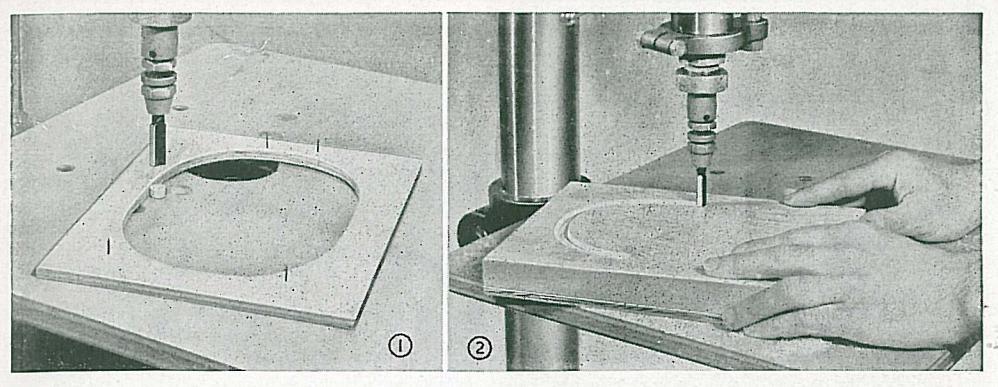
ROUTING IRREGULAR curves which cannot be guided by WITH means of a straight or other simple fence must PATTERN be worked with the use of a pattern. The pattern
is generally of thin plywood. The shape ot the pattern is the same as the required line of routing. Fig. 1 shows the pattern for routing an oval. Fig. l also shows the guide pin against which the pattern rides. The guide pin can be wood or metal. It must be the same digmeter as the router bit and must be centered exactly below the router bit. The pattern is nailed or otherwise fastened to the underside of the work. It can be seen Fig. 2 and Fig. 4 that if the pattern is kept in contact with the guide pin, the router bit will cut the same exact pattern in the work. Fig. 5 shows various sizes of guide pins for different bits. All can be fitted in one hole drilled in the guxiliary wood table. Bouting can be to any depth and can extend right through the work if desired. In the example shown, if only an oval groove is required, the job is done after the work has been rotated around the quide pin. If the wood inside the oval is to be cut away, this part of the work can be done freehand.
CARVING CARVING is somewhat similar to routing with square nose bits, the main difference being that carving bits are used for rounding or otherwise shaping the work. Fig. 6 shows a typical carving router bit. Fig 8 shows the application of this bit in rounding off edges. A quide pin is used, this being of the same diameter as the end diameter of the bit. As the work is guided against the pin, the bit rounds the edges. Fig. 7 shows a bit with a pilot, that is, a shank at the end which does not cut. This type of bit does not require a guide pin, since the pilot serves this same purpose. A bit of this type cannot be fed into the work because the end does not cut. The type shown in Fig. 6, however, can be worked like a drill, and could be used with pattern to make the entire cut shown in Fig. 8 without first cutting the edges square.
Left, pattern for pattern routing. Above,


Carving router bits with or without pilots are useful for decorative edges.

Miscellaneous DRILL PRESS OPERATIONS
SPOT THE spot finish, also called engine finish, and described generally as damaskeening,
is an attractive finish for metal and one that can be easily done on the drill press. All that is needed is a rod of hard rubber of suitable diameter The drill press should run about 1,500 r. p. m. Abrasive grains, such as emery, aluminum oxide or silicon carbide, of about 150-grit are mixed with oil. The paste is spread lightly and evenly, after which the revolving rubber rod is fed to the work. The rod tip grinds the abrasive grains into the metal, producing a circular spot. The operation is repeated, overlapping the rings a trifle, until the whole surface is covered. The best effect is obtained by the use of a fence and some form of
spacing arrangement to keep the spots in straight lines and regularly spaced. Many effective patterns can be worked out. A uniform feed pressure and duration of contact must be practiced to get good results. Heavy feed pressure should be avoided since this wears the rod too fast, causing the outer edges to become rounded, and the complete circle
is not made. Good work on soft metals can be done with an ordinary pencil eraser. The photo insert shows a typical freehand pattern actual size.
SANDING SANDING with the use of sanding drums is one of the most useful of
all drill press operations. Drums in a wide variety of diameters and lengths can be purchased or made up to suit. Where long drums are used for edge work, it is well to make use of an auxiliary table, as shown in Fig. 1, so that the drum can be projected any distance through the opening and thus utilize all of the sanding surface, moving to a new section as soon as the abrasive wears out. Less expensive, narrow-face drums of 1 inch width are ideal for edge work, and working on average 3/4 inch thick lumber, will wear evenly.
PATTERN SANDING with a pattern is useful sanding when production work is to be done. Fig. 3 shows the set-up. A wooden disk of the same size as the drum is nailed to the auxiliary drill table, centered ex-

actly below the drum. The finished pattern is bradded or otherwise fitted to the work. With the pattern riding the guide collar, it can be seen that the work will be cut down and smoothed to the same exact size and contour as the pattern. This method is useful when a number of similar curved pieces are to be made since one carefully-made pattern can be used on any number of roughly sawn blanks.
DRILLING GLASS is drilled with the use of a brass or steel tube, using a
diameter equal to the size of the hole required. The tube is slotted at the working end with one saw cut as shown in Fig. 2. The tube drill is fed with a mixture of 80-arit silicon carbide abrasive grains combined with turpentine. A putty dam can be built around the spot where the hole is being drilled to retain the abrasive. A drill speed of about 500 r. p. m. should be used. Very small holes can be drilled with a hardened piece of drill rod which has been ground to a tapering, triangular point, as shown in Fig. 3. Lubricate with turpentine in which camphor has been dissolved. This is more in the nature of a fine chipping operation, while the tube method drills the hole by wearing away the glass. Drill straight through with the tube: reverse the work and drill from both sides with the triangular point.
SPINNING HOLLOW rivets can be spun neatly and quickly on the drill press. The tools used are the inexpensive
The tools used are the inexpensive punch and anvil ordinarily used for fitting hollow rivets by a hammering operation. The anvil is bolted to the drill table, directly below the punch which is held in the drill chuck, as shown in Fig. 5. The punch should turn about 1,300 r. p. m. A rivet is inserted through the work, after which the punch is brought into play. Two or three light hammer-like taps on
the feed handle will give best results. Similar to the same operation with a hammer, the rivet must be a snug fit in the hole and must be of a certain length which will just permit the neat rounding-over necessary to form a head.
PLUGS and PLUGS commonly used for capping screw holes DOWELS in boat construction and other work are easily made with the use of a plug cutter, as shown in
right for the second plug cutter, as shown in Fig. 6. Plugs are always cut with the wood grain running across the diameter, as shown. The same plug cutter will cut dowels up to about two inches long. Dowels are cut with the grain running lengthwise. A row is worked on a scrap piece of wood, after which the dowels are cut free. A speed of about 1,300 r. p. m. should be used for dowels; 2,400 r. p. m. for small plugs in thin wood.
CUTTING END cutters in two and three-wing styles are used for cutting rosettes and ornamental buttons. The cutters are similar to regular shaper cutters with the exception that the shape is cut on the end, as can be seen in Fig. 7. Rosettes are frequently spotted in the center of a panel for an ornamental effect. Cutters made especially for cutting buttons have long outer spurs to permit the required depth of cut. The work is thin stock of the required thickness, this being glued with paper between the joints, to a second block of wood, as shown by the dotted line in Fig. 7. After cutting, the buttons are pried loose.


cut. On turnings where it is not possible to ride the work against a guide collar, a pattern of the same shape as the turning can be sawed out and nailed to the underside of the base of the jig. The template rides against a pin in the auxiliary wood drill table, and thus sets the depth of cut for the cutter which works directly above it.
MIXING A heavy piece of wire bent to the shape shown in Fig. 4 makes an efficient paint mixer when run on the drill press at slow speed. The can of paint should be held in the hands while mixing is
being done.
00000
FLUTING THE fluting or reeding of turned work is readily done
FLUTING JIG
1/2" CARRIAGE
3/8" BOLT
on the drill press, using suitable styles of shaper cutters. Fig. 1 shows the operation. Like other shaper jobs, a collar is used to set the depth of cut. A rotating collar is highly desirable for this work, since it will not burn the work. Figs. 2 and 3 show the general construction features of the jig which is used to hold the work. The indexing head has twenty-four holes, which permits 4, 6, 8, 12 and 24
which permits a difference of the seen that the fluting jig is simply a makeshift lathe, provided with a simple headstock and tailstock. The tailstock is free to slide and can be shifted to accommodate any length of turning within the range of the jig. The %-inch headstock shaft is fitted with a spur center having the same diameter hole. The index head is pinned to the shaft by means of a nail. Another nail working through the headstock engages the holes in the index head and thus locks the work at any desired position. In use, any form of simple stop, such as nails driven into the drill table, can be used to set the start and finish of the

26
134×234×65 56"STOCK-
Fluting is done with the use of a simple jig. Left, mixing paint. Below, using the drill press for freehand carving.

Elacip Conversion d
FREEHAND CARVING WHILE a "Crafty" hand ginder is the best tool for freehand carving, excellent work can be done on the drill press. as shown in Fig. 5
on the opposite page. The carving bit or cutter should be mounted in the 5/16 inch collet chuck. Where the shank of the bit is less than this, a suitable split bushing should be used to secure proper mounting. Carving bits should not be used in the Jacobs chuck fitted on tapered spindle since this mounting will not stand side pressure.
SURFACE GRINDING THE milling vise affords one of the best methods of mounting work for surface grinding. Fig. 1 shows the set-up. Any type of
Ing. Fig. 1 shows the set-up. Any type of cup or recessed wheel with ½-inch hole can be used, and is readily mounted on the ½-inch threaded spindle. Where a milling vise is not available, very good surface grinding can be done with the use of a column collar fitted below the drill table, as shown in Fig. 2. If the table clamp is loosened a trifle, the table can be swung back and forth under the wheel. Whatever method is used, the cut should not be heavy. The proper setting can be obtained by bringing the wheel down on the work with a light pressure and clamping the quill. After the work has been swung free of the wheel and the drill started, it will be found that the wheel will take a light cut on the surface.

The milling vise is useful for surface grinding, keyway cutting and other jobs.

CUTTING THE cutting of a keyway, as shown in Fig. 3, KEYWAYS illustrates another typical job using the milling vise. The cutter should be ½-inch shank and should be mounted in a ½-inch collet chuck. The work can be fed either with or against the rotation of the cutter. Only light cuts should be taken; if the cut is too deep the cutter will chatter just the same as a lathe bit chatters when removing too much metal. Successive light
chatters when removing too much metal. Successive light cuts should be made until the keyway is cut to depth. BUFFING CLOTH buffing wheels with ½-inch hole are mounted on the ½-inch threaded spindle as
mounted on the 1/2-inch threaded spinale, as can be seen in Fig. 4. White buffing compound applied to the wheel will give a satin-smooth luster to plastics and metals. Like buffing on any other machine, the work should be held so that the wheel runs away from, and not into, edges and corners. Any type of leather or wood polishing wheel with 1/2-inch hole can be mounted and used on the drill press. With the usual 6-inch diameter wheel, the speed of the drill press should be 2400 to 3300 r. p. m.
SCRATCH SCRATCH brushing for a satin finish on metal BRUSHING is done with a wire brush mounted in the same way as described for buffing. See Fig. 5.
The wire brush is also useful for rough clean-up work on dirty or rusty metal. The drill table provides a means of partly or entirely supporting heavy work while brushing.
Buffing wheels, wire brushes and other
wheels with 1/2-inch hole can be
worked to good advantage.

Sharpening BITS and CUTTERS
DRILL GRINDING
THE point angle of a properly ground drill is 118 degrees, or 59 degrees on each side of the centerline. The angle is measured directly over the cutting lip, and is checked by means of a drill point gage, several types of which are available. The gage shown in Fig. 1 is the type which fits over a steel rule. Fig. 2 shows
the gage applied to one of the cutting lips of the drill. The markings on the scale are used to check the length of the cutting lip. Both lips should be at the same angle, and both lips should be exactly the same length. Like any other cutting tool, the drill must have clearance. This should be from 12 to 15-dearees Clearance can usually be judged by eve, using the drill point gage over the heel of the cutting lip, as shown in Fig. 3.
Grinding the drill consists of removing a small amount of metal from the point while retaining the point angle and lip clearance as described Expert mechanics can do this very accurately by eye, but the average craftsman will do best by using a guide board fitted over the tool rest of the grinder, as shown in Fig. 4. The guide lines at 59 degrees establish the point angle, while the 47 degree lines mark the position for a lip clearance of 12 degrees. The drill is placed against the side of the grinding wheel, as shown in Fig. 5, with the cutting lip in contact with the wheel. From this position
the drill is swung to the second position, at the same time giving it a twist of about onesixth of a full turn. One or two light cuts on each lip will usually bring up a sharp edge. Sharpening on the face of the wheel is shown in the photo. The drill is touched to the wheel at the proper angle, and is then pushed upward. A slight rotation is all that is needed since the upstroke provides most of the reguired clearance.
THINNING THE web of a drill becomes thicker as it approaches the shank, as shown in Fig. 6. On
large drills, this web thickness often becomes excessive as the drill wears down, necessitating very heavy pressure to force it through the work. When this condition arises, the web should be thinned. This can be done on a round edge grinding wheel, working in the flutes, as shown in Figs. 7 and 8. The metal is removed from the immediate point only. The cutting lips should be kept straight, even if it is necessary to grind completely out to the margin after thinning the web. A second method of web thinning is done on the backs of the cutting lips, using a square edge wheel.


Fig. 9 shows the appearance of the drill after thinning the web in this manner, while Fig. 10 shows the operation being done.
DRILL FOR BRASS and other soft metals usually cause the drill to "hoa" BRASS
into the metal. To prevent this the drill can be ground as shown in Fig. 11 removing a small amount of metal from each of the cutting lips. The flat need not be over inch wide. This same style of grinding can be used to advantage in drilling very hard metals.
SHARPENING THE cutting lips are the princi-WOOD BITS pal points requiring sharpen ing. Filing should be done with a suitable size flat file, working through the throat, as shown in Fig. 1. Spurs should be sharpened only on the inside, never on the outside. A flat file with a safe edge should be used, with the safe edge down, as shown in Fig. 2. This permits getting right down to the bottom of the spur without marking the cutting lip. Wear or dropping often bends the spurs to the inside, as shown in Fig. They can be straightened by the application of the method shown in Fig. 4, after which the outer edge can be honed
POUTER ROUTER bits can be sharpened with a file if of carbon steel, and with abrasive sticks BITS if high speed steel. The best guide to proper angles to follow in filing can best be obtained from a new bit of the same pattern. Touch-up work should be done frequently on all types of router bits, and honing at regular intervals will keep the edges sharp indefinitely. Metal should never be removed from the outside of the bit if it is possible to avoid it, since metal removed at this point will reduce the size of the bit. On certain bits such as dovetail bits where the outer rim must be touched to sharpen the bit, care should be used to remove no more metal than is necessary, using a very fine abrasive stick.
MORTISING A SPECIALLY shaped grinding wheel which CHISELS can be chucked in either the lathe or drill press offers the best method of sharpening mortising chisels. The chisel can be centered below the wheel, as shown in Fig. 7, and the wheel brought down, or the chisel can be held in the hand and pushed into the wheel. Clean the corners with a triangular file.
SHAPER SHAPER cutters should be washed in ben-CUTTERS zine or gasoline to remove pitch, after which sharpening can be done with abrasive
sticks. The best method of sharpening is to work from the back, flat side of cutter, as shown in Fig. 6. This will bring up a sharp edge without any danger of spoiling shape of the cutter. Light honing can also be done on the bevel
Above, sharpening wood bits. Photos below show sharpening of other drill press tools.


Electric DRILLS THE electric drill consists of a
THE ELECTRIC DRILL
motor in a compact framework. The motor is generally of a high speed universal type, which is coupled to the chuck shank through a gear box to provide a speed reduction and added power. Electric drills are commonly described according to the capacity of the chuck. Thus, a unit which will take drills up to 3% inch is called a 3% inch drill. The average no-load speed of a 1/4-inch electric drill is about 1,800 r. p. m. This is approximately correct for all types of work, since the motor will slow down somewhat in drilling hard steel. Larger units are proportionately slower speed. The motor switch is usually located on the handle, as shown in Fig. 2, so that the drill can be easily turned on or off. Some drills are fitted with a three-wire cord, the third wire being a ground wire, as shown in Fig. 1. In operation, this wire should be connected to a pipe or other ground connection. Its purpose is to pre-vent shocks and it will ground the current if any short circuit in the motor should occur. However, any three-wire connected drill can be used without the ground wire, and, as such, is as safe as any twowire connection and will not shock the operator unless the motor goes bad.
DRILLING DRILLING with an electric drill is simply a matter of "punching holes," and hardly needs any detailed description. Where holes are to be drilled to exact depth, a metal stop gage can be used, or, the drill can be fitted with a
wooden sleeve, as shown in Fig. 3. A guide block, used as shown in Fig. 4. will insure accuracy where exact squareness is required. Where both location and squareness must be exact, a guide block with pilot hole, as shown in Fig. 5, will insure perfect drilling. Accurate work of all kinds is best done if the drill is placed on the punch mark before pulling the switch rather than stabbing at the location with the motor running. Short, stubby drills give best results.
OTHER FITTED with a sanding drum, OPERATIONS the electric drill makes an excellent sander. particularly useful on jobs which cannot be moved to or worked on the drill press. A standard accessory for the electric drill is the grinding wheel arbor shown in Fig. 2. This will take grinding wheels, buffing wheels, wire brushes, sanding disks, etc., and enables the operator to do a wide variety of work in cleaning, sanding and polishing. Grinding and wire wheels should usually be no larger than 4-inch diameter and should be fitted with a wheel guard to insure safety in operation.
ingtes any danshows various

TABLES
| DECIMAL EQUIVALENTS | ||||||||||
|---|---|---|---|---|---|---|---|---|---|---|
|
1/64 = .015625
1/32 = .03125 3/64 = .046875 |
1/4 = .250
17/64 = .265625 9/32 = .28125 19/64 = .296875 |
1/2 = .500
33/64 = .515625 17/32 = .53125 35/64 = .546875 |
3/4 = .750
49/64 = .765625 25/32 = .78125 51/64 = .796875 |
|||||||
| 1/16 = .0625 | 5 /16 = .3125 | 9/16 = .5626 | 13/16 = .8125 | |||||||
| 5/64 = .078125 | 21/64 = .328125 | 37/64 = .578125 | 53/64 = .828125 | |||||||
| 3/32 = .09375 | 11/32 = .34375 | 19/32 = .59375 | 27/32 = .84375 | |||||||
| 7/64 = .109375 | 23/64 = .359375 | 39/64 = .609375 | 55/64 = .859375 | |||||||
| 1/8 = .125 | 3/8 = .375 | 5/8 = .625 | 7/8 = .875 | |||||||
| 9/64 = .140625 | 25/64 = .390625 | 41/64 = .640625 | 57/64 = .890625 | |||||||
| 5/32 = .15625 | 13/32 = .40625 | 21/32 = .65625 | 29/32 = .90625 | |||||||
| 11/64 = .171875 | 27/64 = .421875 | 43/64 = .671875 | 59/64 = .921875 | |||||||
| 3/16 = .1875 | 7/16 — .4375 | 11/16 = .6875 | 15/16 = .9375 | |||||||
| 13/64 = .203125 | 29/64 — .453125 | 45/64 = .703125 | 61/64 = .953125 | |||||||
| 7/32 = .21875 | 15/32 — .46875 | 23/32 = .71875 | 31/32 = .96875 | |||||||
| 15/64 = .234375 | 31/64 — .484375 | 47/64 = .734374 | 63/64 = .984375 | |||||||
| C | IAMETER | S OF | NUMBERI | LLS | » | LETTERED | DRILLS | |
|---|---|---|---|---|---|---|---|---|
| Drill | Diameter | Drill | Diameter | Drill | Diameter | Drill | Diameter | |
| No. | Inches | No. | Inches | No. | Inches | No. | Inches | |
| 80 | .0135 | 53 | .0595 | 26 | .1470 | A—15/64 | .2340 | |
| 79 | .0145 | 52 | .0635 | 25 | .1495 | B | .2380 | |
| 78 | .0160 | 51 | .0670 | 24 | .1520 | C | .2420 | |
| 77 | .0180 | 50 | .0700 | 23 | .1540 | D | .2460 | |
| 76 | .0200 | 49 | .0730 | 22 | .1570 | E—1/4 | .2500 | |
| 75 | .0210 | 48 | .0760 | 21 | .1590 | F | .2570 | |
| 74 | .0225 | 47 | .0785 | 20 | .1610 | G | .2610 | |
| 73 | .0240 | 46 | .0810 | 19 | .1660 | H—17/64 | .2660 | |
| 72 | .0250 | 45 | .0820 | 18 | .1695 | I | .2720 | |
| 71 | .0260 | 44 | .0860 | 17 | .1730 | J | .2770 | |
| 70 | .0280 | 43 | .0890 | 16 | .1770 | K—9/32 | .2810 | |
| 69 | .0292 | 42 | .0935 | 15 | .1800 | L | .2900 | |
| 68 | .0310 | 41 | .0960 | 14 | .1820 | M—19/64 | .2950 | |
| 67 | .0320 | 40 | .0980 | 13 | .1850 | N | .3020 | |
| 66 | .0330 | 39 | .0995 | 12 | .1890 | O—5/16 | .3160 | |
| 65 | .0350 | 38 | .1015 | 11 | .1910 | P—21/64 | .3230 | |
| 64 | .0360 | 37 | .1040 | 10 | .1935 | Q | .3320 | |
| 63 | .0370 | 36 | .1065 | 9 | .1960 | R—11/32 | .3390 | |
| 62 | .0380 | 35 | .1100 | 8 | .1990 | S | .3480 | |
| 61 | .0390 | 34 | .1110 | 7 | .2010 | T—23/64 | .3580 | |
|
60
59 58 57 |
.0400
.0410 .0420 .0430 |
33
32 31 30 |
.1130
.1160 .1200 .1285 |
6543 |
.2040
.2055 .2090 .2130 |
U
V—3/8 W—25/64 X |
.3680
.3770 .3860 .3970 |
|
|
56
55 54 |
.0465
.0520 .0550 |
29
28 27 |
,1360
.1405 .1440 |
2
1 |
.2210
.2280 |
Y—13/32
Z |
.4040
.4130 |
N. B. ILLUSTRATIONS in this book picture the CRAFTSMAN 15-inch Floor Model Drill Press. The working methods described can be applied generally to any CRAFTSMAN, COMPANION or other drill press. The accessories shown are standard items in Sears complete line of power tools, with the exception of a few items of limited use which have been included to make the text as complete as possible.
| Mate | Material Turning | Chucking | Millin |
a
a |
Reaming | ping | ||||||
| Tool SteelDry or OilSoft SteelDry or Soda WaWrought IronDry or Soda WaCast IronDryBrassDryCopperDryBabbittDryAluminumKerosene or Tur |
Water
Water Turp. |
Oil or Soda Wate
Soda Water Dry Dry Oil Dry Kerosene or Turp |
ater C
C I I rp. K |
Dil
Dil or Soc Dil or Soc Dry Dry Dil Dry Cerosene o |
Lard Oil
Lard Oil Dry Dry Oil Dry or ke Kerosene |
Oil
Oil Oil Oil Oil Oil Oil Oil Oil Oil |
||||||
|
The best type of lubricating oil is pure lard oil.
Soda water is made by dissolving sal soda in water. |
||||||||||||
| DRILLS FOR WOOD SCREWS DRILL PRESS OPERATIONS | ||||||||||||
|
Gage
of Screw |
Gage Dia. Body Lead
of in Hole Hole Screw Decimals Drill Drill |
"Bore
Drill |
Operation Speed
in R.P.M. |
|||||||||
|
0
1 2 3 4 5 6 7 8 8 9 10 11 12 14 16 18 |
.058
.071 .084 .097 .111 .124 .137 .150 .163 .177 .190 .202 .219 .242 .269 .294 |
3
1 4 7 1 4 7 7 0 3 3 7 0 2 2 5 2 2 9 9 4 |
53
49 44 40 33 36 28 28 24 19 15 10 5 %2 D I 1 9 %4 |
68
57 56 52 52 47 42 42 42 38 38 38 31 28 23 |
32
20 16 4 F L O S T X 7/6 %4 3%4 3%4 |
BORIN
BORIN CARVI CARVI DOVE GLAS GRINE GRINE GRINE MORT MORT MORT PLUG ROUT SAND SHAPI SPINN *Speed bits. If speed four-speed four-speed |
IG (Bits u
IG (Bits u IG (Bits u IG (Bits u IG (Bits u IG (Bits u IIG WIT TAILING SL CUTT. S (Drilling) ING (En NG (Ligh ISING (F ISING (G UTTIN ING (Wo ING (Mo ING (% i ING (% i ING (% i Speeds ( Speeds, us) |
p to 1/2 is
prer l in. "H SMAI ING |
n.)
) |
2400
1300 600 5200 2400 600 2400 1300 600 600 1300 1300 1300 5200 1300 5200 1300 5200 1300 5200 2400 cutters and e next lower fit a typical press has hese figures. |
||
| DRIL | L | SPEED | S II | NR. | P. M.* | • | ||||||
|
Dril
Dia |
1 |
Tool
Steel |
Mild
Steel |
Cas |
st
n |
Soft
Metals |
Drill
Dia. |
Tool
Steel |
Mild
Steel |
Cast
Iron |
Soft
Metals |
|
|
1/3
3/3 1 5/3 |
16
32 /8 32 |
1833
1375 917 764 |
3667
2750 1833 1527 |
427
320 213 178 |
78
08 39 32 |
9168
6875 4584 3820 |
1 |
1/2
9/16 5/8 1/16 |
229
206 183 168 |
458
412 367 336 |
535
481 428 392 |
1146
1031 917 840 |
|
3/
7/: 1 9/: |
16
32 /4 32 |
611
534 458 •412 |
1222
1069 917 825 |
142
124 107 96 |
26
18 70 53 |
3056
2674 2292 2062 |
3/4
13/16 7/8 15/16 |
153
142 131 123 |
306
284 262 245 |
357
331 306 286 |
764
709 655 614 |
|
|
5/
11/3 3 |
16
32 /8 |
367
336 306 |
733
672 611 |
85
78 71 |
56
34 13 |
1833
1680 1528 |
1
1 1 |
l-
l-1/8 l-1/4 |
115
102 92 |
229
204 183 |
267
238 214 |
573
509 458 |
|
13/3
7/ 15/3 |
13/32 284 567 6
7/16 262 524 6 15/32 245 491 5 |
66
61 57 |
52
11 73 |
1419
1310 1228 |
l-3/8
l-1/2 l-5/8 |
83
76 70 |
167
153 141 |
194
178 165 |
417
382 353 |
|||
 Instruction Guides")


 Loading...