

Sears YTH24V48 Owner's Manual

Gasoline containing up to 10% ethanol (EIO) ia accept=
able for use in this machine. The use of any gasoline ex-
ceeding 10% ethanol(ElO) wiHvoidtheproductwarrantyo
Eata maquina puede utilizar gasolins con un contenido
de haata e! 10% de etanol (E10)o EJuao de una gaaolina
que supers el 10% de etanoi (EIO) anulata ta garantia
deJ productoo the product warranty°
586 12 04°26
Operator's Manual
Manuat de Operario
Please read the operator's manual carefully and make sure
you understand the instructions before using the machine.
Por favor lea cuidadosamente y comprenda
estas intrucciones antes de usar esta maquina.
SAFETY RULES
Safe Operation Practices for Ride-On Mowers
DANGER: THiS CUTTING MACHINE iS CAPABLE OF AMPUTATING HANDS AND FEET AND THROWING OBJECTS. FAILURE
TO OBSERVE THE FOLLOWING SAFETY iNSTRUCTiONS COULD RESULT iN SERIOUS iNJURY OR DEATH.
WARNmNG: _n order to prevent accidental
starting when setting up, transporting,
adjusting or making repairs, always discon-
nect spark plug wire and place wire where
it cannot contact spark plug.
i WARNNNG_own a hill in neuto
ral, you may _ose eontro_ of the tractor.
WARNING: Tow onJy the attachments that
are recommended by and comply with
specifications of the manufacturer of your
tractor. Use common sense when towing.
Operate only at the lowest possible speed
when on a slope. Too heavy ofa load,while
on a slope, i8 dangerous. Tires can Jose
traction with the ground and cause you to
_ose eontro_ of your tractor.
WARNING
Engine exhaust, some of its constituents, and certain
vehieJe components contain or emit chemicals
known to the State of California to cause cancer
and birth defects or other reproductive harm.
WARNING
Battery posts, terminals and related accessories
contain lead and Jead compounds, chemicals known
to the State of California to cause cancer and birth
defects or other reproductive harm. Wash hands
after handling.
L GENERAL OPERATION
o Read, understand, and follow all instructions on the ma-
chine and in the manual before starting.
o Do not put hands or feet near rotating parts or under the
machine. Keep clear of the discharge opening at all times.
o Only allow responsible adults, who are familiar with the
instructions, to operate the machine.
o Clear the area of objects such as rocks, toys, wire, etc.,
which could be picked up and thrown by the blades.
o Ensure the area is clear of bystanders before operating.
Stop machine if anyone enters the area.
o Never carry passengers.
o Do not mow in reverse unless absolutely necessary.
Always look down and behind before and while backing.
o Never direct discharged material toward anyone. Avoid
discharging material against a wall or obstruction. Material
may ricochet back toward the operator. Stop the blades
when crossing gravel surfaces.
o Do notoperate machinewithout theentire grass catcher, dis-
charge chute, or other safety devices in place and working.
o Slow down before turning.
o Never leave a running machine unattended. Always turn
off blades, set parking brake, stop engine, and remove
keys before dismounting.
o Disengage blades when not mowing. Shut off engine
and wait for all parts to come to a complete stop before
cleaning the machine, removing the grass catcher, or
unclogging the discharge chute.
o Operate machine only in daylight or good artificial light.
o Do not operate the machine while under the influence of
alcohol or drugs.
o Watch for traffic when operating near or crossing roadways.
o Use extra care when loading or unloading the machine
into a trailer or truck.
o Always wear eye protection when operating machine.
o Data indicates that operators, age 60 years and above,
are involved in a large percentage of riding mower-related
injuries. These operators should evaluate their ability to
operate the riding mower safely enough to protect them-
selves and others from serious injury.
o Follow the manufacturer's recommendation for wheel
weights or counterweights.
o Keep machine free of grass, leaves or other debris build-up
which can touch hot exhaust / engine parts and burn. Do
not allow the mower deck to plow leaves or other debris
which can cause build-up to occur. Clean any oil or fuel
spillage before operating or storing the machine. Allow
machine to cool before storage.
H. SLOPE OPERATION
Slopes are a major factor related to loss of control and tip-
over accidents, which can result in severe injury or death.
Operation on all slopes requires extra caution. If you cannot
back up the slope or if you feel uneasy on it, do not mow it.
o Mow up and down slopes, not across.
o Watch for holes, ruts, bumps, rocks, or other hidden ob-
jects. Uneven terrain could overturn the machine. Tall
grass can hide obstacles.
o Choose a low ground speed so that you will not have to
stop or shift while on the slope.
o Do not mow on wet grass. Tires may lose traction.
Always keep the machine in gear when going down slopes.
Do not shift to neutral and coast downhill.
o Avoid starting, stopping, or turning on a slope. If the tires
lose traction, disengage the blades and proceed slowly
straight down the slope.
o Keep all movement on the slopes slow and gradual. Do
not make sudden changes in speed or direction, which
could cause the machine to roll over.
o Use extra care while operating machine with grass catch-
ers or other attachments; they can affect the stability of
the machine. Do no use on steep slopes.
o Do not try to stabilize the machine by putting your foot
on the ground.
o Do not mow near drop-offs, ditches, or embankments. The
machine could suddenly roll over if a wheel is over the edge
or ifthe edge caves in.
2
SAFETY RULES
Safe Operation Practices for Ride-On Mowers
ill. CHILDREN
WARNING. CHILDREN CAN BE iNJURED BY
TH_S EQUIPMENT. The American Academy
of Pediatrics recommends that children be a
minimum of 12 year of age before operating
a pedestrian controlled _awn mower and a
minimum of 16 years of age before operating
a riding lawn mower.
Tragic accidents can occur if the operator is not alert to the
presence of children. Children are often attracted to the ma=
chine and the mowing activity. Never assume that children
will remain where you last saw them.
o Keep children out of the mowing area and in the watchful
care of a responsible adult other than the operator.
o Be alert and turn machine off if a child enters the area.
o Before and wNle backing, look beMnd and down for small
children.
o Never carry children, even with the blades shut off. They
may fall off and be seriously injured or interfere with safe
machine operation. Children who have been given rides
in the past may suddenly appear in the mowing area for
another ride and be run over or backed over by the machine.
o Never allow children to operate the machine.
o Use extra care when approaching blind corners, shrubs,
trees, or other objects that may block your view of a child.
o If fuel is spilled on clothing, change clothing immediately.
o Never overfill fuel tank. Replace gas cap and tighten
securely.
GENERAL SERWCE
o Never operate machine in a closed area.
o Keep all nuts and bolts tight to ensure the equipment is
in safe working condition.
o Never tamper with safety devices. Check their proper
operation regularly.
o Keep machine free of grass, leaves, or other debris build=
up. Clean oil or fuel spillage and remove any fuel-soaked
debris. Allow machine to cool before storing.
o Ifyou strike aforeign object, stop and inspect the machine.
Repair, if necessary, before restarting.
o Never make any adjustments or repairs with the engine
running.
o Check grass catcher components and the discharge chute
frequently and replace with manufacturer's recommended
parts, when necessary.
o Mower blades are sharp. Wrap the blade or wear gloves,
and use extra caution when servicing them.
o Check brake operation frequently. Adjust and service as
required.
o Maintain or replace safety and instruction labels, as nec=
essary.
_VoTOWING
o Tow only with a machine that has a hitch designed for
towing. Donot attach towed equipment except atthe hitch
point.
o Follow the manufacturer's recommendation for weight
limits for towed equipment and towing on slopes.
o Never allow children or others inor on towed equipment.
o On slopes, the weight of the towed equipment may cause
loss of traction and loss of control.
o Travel slowly and allow extra distance to stop.
V. SERVICE
SAFE HANDUNG OF GASOLINE
To avoid personal injury or property damage, use extreme
care in handling gasoline. Gasoline is extremely flammable
and the vapors are explosive.
o Extinguish all cigarettes, cigars, pipes, and other sources
of ignition.
o Use only approved gasoline container.
o Never remove gas cap or add fuel with the engine running.
Allow engine to cool before refueling.
o Never fuel the machine indoors.
o Never store the machine or fuet container where there
is an open flame, spark, or pilot light such as on a water
heater or other appliances.
o Never fill containers inside a vehicle or on a truck or
trailer bed with plastic liner. Always place containers on
the ground away from your vehicle when filling.
o Remove gas=powered equipment from the truck or trailer
and refuel it on the ground. If this is not possible, then
refuel such equipment with a portable container, rather
than from a gasoline dispenser nozzle.
o Keep the nozzle in contact with the rim of the fuel tank or
container opening at all times until fueling is complete.
Do not use a nozzle lock=open device.
o Ensure the area is clear of bystanders before operating.
Stop machine if anyone enters the area.
o Never carry passengers.
o Do not mow in reverse unless absolutely necessary.
Always look down and behind before and while backing.
o Never carry children, even with the blades shut off. They
may fall off and be seriously injured or interfere with safe
machine operation. Children who have been given rides
in the past may suddenly appear in the mowing area
for another ride and be run over or backed over by the
machine.
o Keep children out of the mowing area and in the watchful
care of a responsible adult other than the operator.
o Be alert and turn machine off if a child enters the area.
o Before and while backing, look behind and down for small
children.
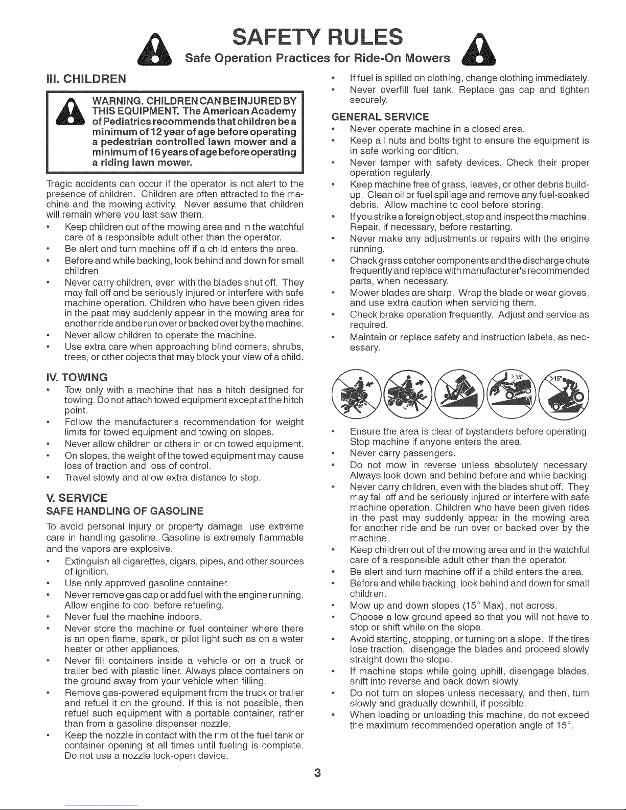
o Mow up and down slopes (15 ° Max), not across.
o Choose a low ground speed so that you will not have to
stop or shift while on the slope.
o Avoid starting, stopping, or turning on a slope. If the tires
lose traction, disengage the blades and proceed slowly
straight down the slope.
o If machine stops while going uphill, disengage blades,
shift into reverse and back down slowly.
o Do not turn on slopes unless necessary, and then, turn
slowly and gradually downhill, if possible.
o When loading or unloading this machine, do not exceed
the maximum recommended operation angle of 15°.
3

PRODUCT SPECIFICATIONS
Gasoline Capacity 3.0 Gallons {11.36 L)
and type: Unleaded Regular
Oil Type: SAE 30 (above 32°F/0°C)
(API: SG-SL) SAE 5W30 (above 32°F/0°C)
Oil Capacity: w/Filter: 64 oz. (1.96 L)
w/o Filter: 60 oz. (1.77 L)
Spark Plug: Champion RC12YC
Gap: .030"(.76 mm)
Charging System: 16 AMPS @ 3600 RPM
Battery: Amp/Hr: 28
Min. CCA: 230
Case Size: U1R
Blade Bolt Torque: 45-55 FT. LBS. (62-75 Nm)
CONGRATULATIONS on your purchase of anew tractor.
It has been designed, engineered and manufactured to
give you the best possible dependability and performance.
Should you experience any problem you cannot easily
remedy, please contact your nearest authorized service
center/department. We have competent, well-trained techni-
cians and the proper tools to service or repair this tractor.
Please read and retain this manual. The instructions will
enable you to assemble and maintain your tractor properly.
Always observe the "SAFETY RULES".
CUSTOMER RESPONSIBILITIES
Read and observe the safety rules.
Follow a regular schedule in maintaining, caring for
and using your tractor.
Follow the instructions under "Maintenance" and "Stor-
age" sections of this manual.
Wear proper Personal Protective Equipment (PPE)
while operating this machine, including (at a minimum)
sturdy footwear, eye protection, and hearing protection.
Do not mow in shorts and/or, open toed footwear.
Always let someone know you are outside mowing.
WARNING: This tractor is equipped with an internal com-
bustion engine and should not be used on or near any un-
improved forest-covered, brush-covered or grass-covered
land unless the engine's exhaust system is equipped with
a spark arrester meeting applicable local or state laws (if
any). If a spark arrester is used, it should be maintained
in effective working order by the operator.
A spark arrester for the muffler is available through your
nearest authorized service center/department.
In the state of California the above is required by law
(Section 4442 of the California Public Resources Code).
Other states may have similar laws. Federal laws apply
on federal lands.
TABLE OF CONTENTS
SAFETY RULES ......................................................... 2-3
PRODUCT SPECLFICAT_ONS ....................................... 4
CUSTOMER RESPONSIBIUTIES ................................. 4
ASSEMBLY ................................................................. 5-6
OPERATmON ............................................................. 7-13
MAINTENANCE SCHEDULE ...................................... 14
MAINTENANCE ..................................................... 14-18
SERVICE AND ADJUSTMENTS ............................ 19o25
STORAGE .................................................................... 26
TROUBLESHOOTING ............................................ 27°28
WARRANTY ............................................................ 30°33
ESPANOL .................................................................... 34
4
Keys
UNASSEMBLED
Smope Sheet
(1) Oil Drain Tube
Key(s)
.... (1) Quick
il_gill]ilj Connect
ASSEMBLY
Your new tractor has been assembled at the factory with the exception of those parts left unassembled for shipping purposes.
TOOLS REQUIRED FOR ASSEMBLY
A socket wrench set will make assembly easier. Standard
wrench sizes are listed.
(1) 1/2" wrench Tire pressure gauge
(2) 7/16" wrenches Utility knife Pliers
When right or left hand ismentioned in this manual, itmeans
when you are in the operating position (seated behind the
steering wheel).
TO REMOVE TRACTOR FROM CARTON
UNPACK CARTON
Remove all accessible loose parts and parts cartons
from carton.
Remove end panels and lay side panels flat.
Check for any additional loose parts or cartons and
remove.
For battery and battery cable installation see "RE-
PLACING BATTERY" inthe "Service and Adjustments"
section in this manual.
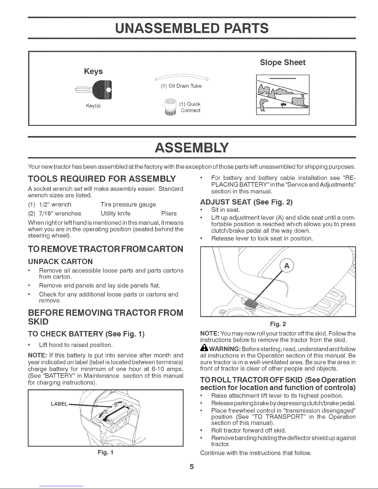
ADJUST SEAT (See Fig. 2)
Sit in seat.
o Lift up adjustment lever (A) and slide seat until a com-
fortable position is reached which allows you to press
clutch/brake pedal all the way down.
Release lever to lock seat in position.
BEFORE REMOVING TRACTOR FROM
TO CHECK BATTERY (See Fig. 1)
o Lift hood to raised position.
NOTE: If this battery is put into service after month and
year indicated on label (label is located between terminals)
charge battery for minimum of one hour at 6-10 amps.
(See "BATTERY" in Maintenance section of this manual
for charging instructions).
LABEL
Fig. 1
Fig. 2
NOTE: You may now rollyour tractor off the skid. Follow the
instructions bemowto remove the tractor from the skid.
_I_,WARN_NG: Before starting, read, understand and follow
all instructions in the Operation section of this manual. Be
sure tractor is in a weIFventilated area. Be sure the area in
front of tractor is clear of other people and objects.
TO ROLLTRACTOR OFF SKiD (See Operation
section for _ocation and function of controls)
o Raise attachment lift lever to its highest position.
o Release parking brake bydepressing clutch!brake pedal.
o Place freewheel control in "transmission disengaged"
position (See "TO TRANSPORT" in the Operation
section of this manual).
o Roll tractor forward off skid.
o Remove banding holding the deflector shield up against
tractor.
Continue with the instructions that follow.
5

ASSEMBLY
CHECK TiRE PRESSURE
The tires on your tractor were ovednflated at the factory
for shipping purposes. Correct tire pressure is important
for best cutting performance.
Reduce tire pressure to PSI shown on tires.
CHECK DECK LEVELNESS
For best cutting results, mower housing should be prop-
erly leveled. See "TO LEVEL MOWER HOUSING" in the
Service and Adjustments section of this manual.
BEFORE YOU OPERATE YOUR NEW TRACTOR, WE
WISH TO ASSURE THAT YOU RECEIVE THE BEST
PERFORMANCE AND SATISFACTION FROM THIS
QUALITY PRODUCT.
PLEASE REWEW THE FOLLOWING CHECKLIST
_f All assembly instructions have been completed.
_f No remaining loose parts in carton.
CHECK FOR POSITION OF ALL
See the figures that are shown for replacing motion and
mower blade drive belts in the Service and Adjustments
section of this manual. Verify that the belts are routed
correctly.
CHECK BRAKE SYSTEM
After you learn how to operate your tractor, check to see that
the brake is operating properly. See "TO CHECK BRAKE"
in the Service and Adjustments section of this manual.
_f Battery is properly prepared and charged.
_f Seat is adjusted comfortably and tightened securely.
_f All tires are properly inflated. (For shipping purposes,
the tires were overinflated at the factory).
_f Be sure mower deck is properly leveled side-to-side/
front-to-rear for best cutting results. (Tires must be
properly inflated for leveling).
_f Check mower and drive belts. Be sure they are routed
properly around pulleys and inside all belt keepers.
_f Check wiring. See that all connections are still secure
and wires are properly clamped.
_f Before driving tractor, be sure freewheel control is in
"transmission engaged" position (see "TO TRANS-
PORT" in the Operation section of this manual).
WHILE LEARNING HOWTO USE YOUR TRACTOR, PAY
EXTRA ATTENTION TO THE FOLLOWING IMPORTANT
ITEMS:
_f Engine oil is at proper level.
_f Fuel tank is filled with fresh, clean, regular unleaded
gasoline.
_f Become familiar with all controls, their location and
function. Operate them before you start the engine.
_f Be sure brake system is in safe operating condition.
_f Be sure Operator Presence System and Reverse Op-
eration System (ROS) are working properly (See the
Operation and Maintenance sections in this manual).
_f It is important to purge the transmission before operat-
ing your tractor for the first time. Follow proper start-
ing and transmission purging instructions (See "TO
START ENGINE" and "PURGE TRANSMISSION" in
the Operation section of this manual).
6

OPERATION
These symbols may appear on your tractor or in literature supplied with the product. Learn and understand their meaning.
SLOWREVERSE NEUTRAL HIGH LOW FAST COLD WEATHER IGNITION SWITCH
STARTING
POSITION
ENGINE OFF ENGINE ON ENGINE START PARKING BRAKE MOWER HEIGHT MOWER LIFTLIGHTS ON
Fm
FUEL BATTERY
OPERATION PEDAL
SYSTEM (ROS)
ATTACHMENT
CLUTCH DISENGAGED
FREE WHEEL
(Automatic Models only)
ATTACHMENT
CLUTCH ENGAGED
FaiEure to foEEowinstructions
couEd resuEt in serious injury or
death. The safety aEert symboE
is used to identify safety inform-
ation about hazards which can
resuk in death, serious injury
and/or property damage.
REVERSE FORWARD CRUISE CONTROLREVERSE CLUTCH/BRAKE
@@
DANGER, KEEP HANDS
AND FEET AWAY
DANGER indicates a hazard which, if not avoided,
will result in death or serious iniury.
WARNUNG indicates a hazard which, if not avoided,
could result in death or serious injury.
CAUTUON indicates a hazard which, if not avoided,
might result in minor or moderate injury.
CAUTUON when used without the alert symbol,
indicates a situation that could result in damage
to the tractor and/or engine.
HOT SURFACES indicates a hazard which,
if not avoided, could result in death, serious injury
and/or property damage.
FURE indicates a hazard which, if not avoided,
could result in death, serious injury and/or
property damage.
KEEP AREA CLEAR SLOPE HAZARDS
(SEE SAFETY RULES SECTION)
7
OPERATION
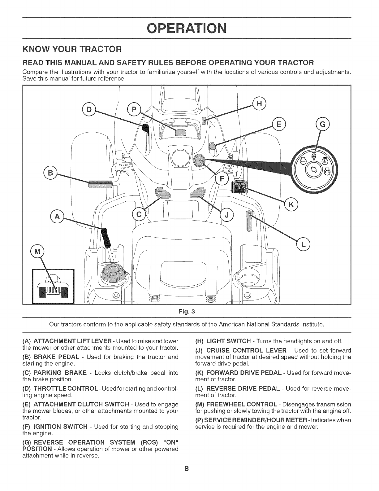
KNOW YOUR TRACTOR
READ THiS MANUAL AND SAFETY RULES BEFORE OPERATING YOUR TRACTOR
Compare the illustrations with your tractor to familiarize yourself with the locations of various controls and adjustments.
Save this manual for future reference.
Our tractors conform to the applicable safety standards of the American National Standards Institute.
(A} ATTACHMENT UFT LEVER - Used to raise and lower
the mower or other attachments mounted to your tractor.
(B) BRAKE PEDAL - Used for braking the tractor and
starting the engine.
(C) PARKING BRAKE - Locks clutch/brake pedal into
the brake position.
(D) THROTTLE CONTROL- Used for starting and controF
ling engine speed.
(E) ATTACHMENT CLUTCH SWITCH - Used to engage
the mower blades, or other attachments mounted to your
tractor.
(F} _GN_TmONSWITCH - Used for starting and stopping
the engine.
(G) REVERSE OPERATION SYSTEM (ROS) "ON"
POSIT_ON - Allows operation of mower or other powered
attachment while in reverse.
Fig. 3
(H) LIGHT SWITCH - Turns the headlights on and off.
(J) CRUISE CONTROL LEVER - Used to set forward
movement of tractor at desired speed without holding the
forward drive pedal.
(K} FORWARD DRIVE PEDAL - Used for forward move-
ment of tractor.
(L) REVERSE DRIVE PEDAL - Used for reverse move-
ment of tractor.
(M) FREEWHEEL CONTROL - Disengages transmission
for pushing or slowly towing the tractor with the engine off.
(P) SERVmCEREMINDER/HOUR METER-Indicateswhen
service is required for the engine and mower.
8
OPERATION
The operation of any tractor can reault in foreign object$ thrown into the eyea, which can
reault in aevere eye damage. Always wear aafety glaaaea or eye ahields while operating
your tractor or performing any adjuatmenta or repaira. We recommend atandard aafety
glaaaea or a wide viaion aafety maak worn over apeetacmea.
HOW TO USE YOUR TRACTOR
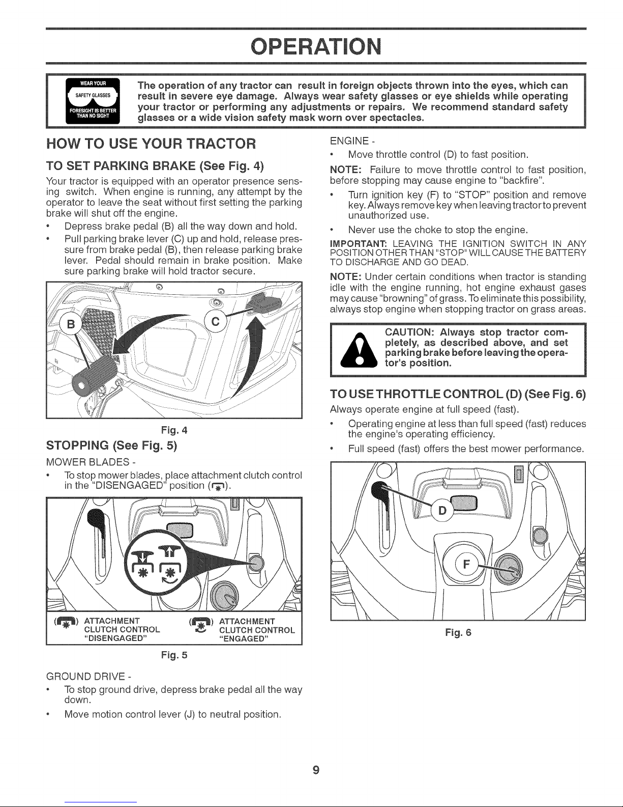
TO SET PARKING BRAKE (See Fig. 4}
Your tractor is equipped with an operator presence sens-
ing switch. When engine is running, any attempt by the
operator to leave the seat without first setting the parking
brake will shut off the engine.
. Depress brake pedal (B) all the way down and hold.
o Pull parking brake lever (C) up and hold, release pres-
sure from brake pedal (B), then release parking brake
lever. Pedal should remain in brake position. Make
sure parking brake will hold tractor secure.
Fig. 4
STOPPING (See Fig. 5}
MOWER BLADES =
. To stop mower blades, place attachment clutch control
in the "DISENGAGED" position (r_).
ENGINE =
. Move throttle control (D) to fast position.
NOTE: Failure to move throttle control to fast position,
before stopping may cause engine to "backfire".
. Turn ignition key (F) to "STOP" position and remove
key.Always remove key when leaving tractor to prevent
unauthorized use.
. Never use the choke to stop the engine.
iMPORTANT: LEAVING THE IGNITION SWITCH iN ANY
POSITION OTHER THAN "STOP" WILL CAUSE THE BATTERY
TO DISCHARGE AND GO DEAD.
NOTE: Under certain conditions when tractor is standing
idle with the engine running, hot engine exhaust gases
may cause "browning" of grass. Toeliminate this possibility,
always stop engine when stopping tractor on grass areas.
pletely, as described above, and eet
parking brake before leaving the opera°
CAUTION: Always stop tractor com-
tor'a position.
TO USE THROTTLE CONTROL (D} (See Fig. 6}
Always operate engine at fuji speed (fast).
. Operating engine at less than full speed (fast) reduces
the engine's operating efficiency.
. Full speed (fast) offers the best mower performance.
(|) ATTACHMENT
CLUTCH CONTROL
"DISENGAGED"
(_) ATTACHMENT
Fig. 5
GROUND DRIVE =
. To stop ground drive, depress brake pedal all the way
down.
. Move motion control lever (J) to neutral position.
CLUTCH CONTROL
"ENGAGED"
Fig. 6
9
OPERATION
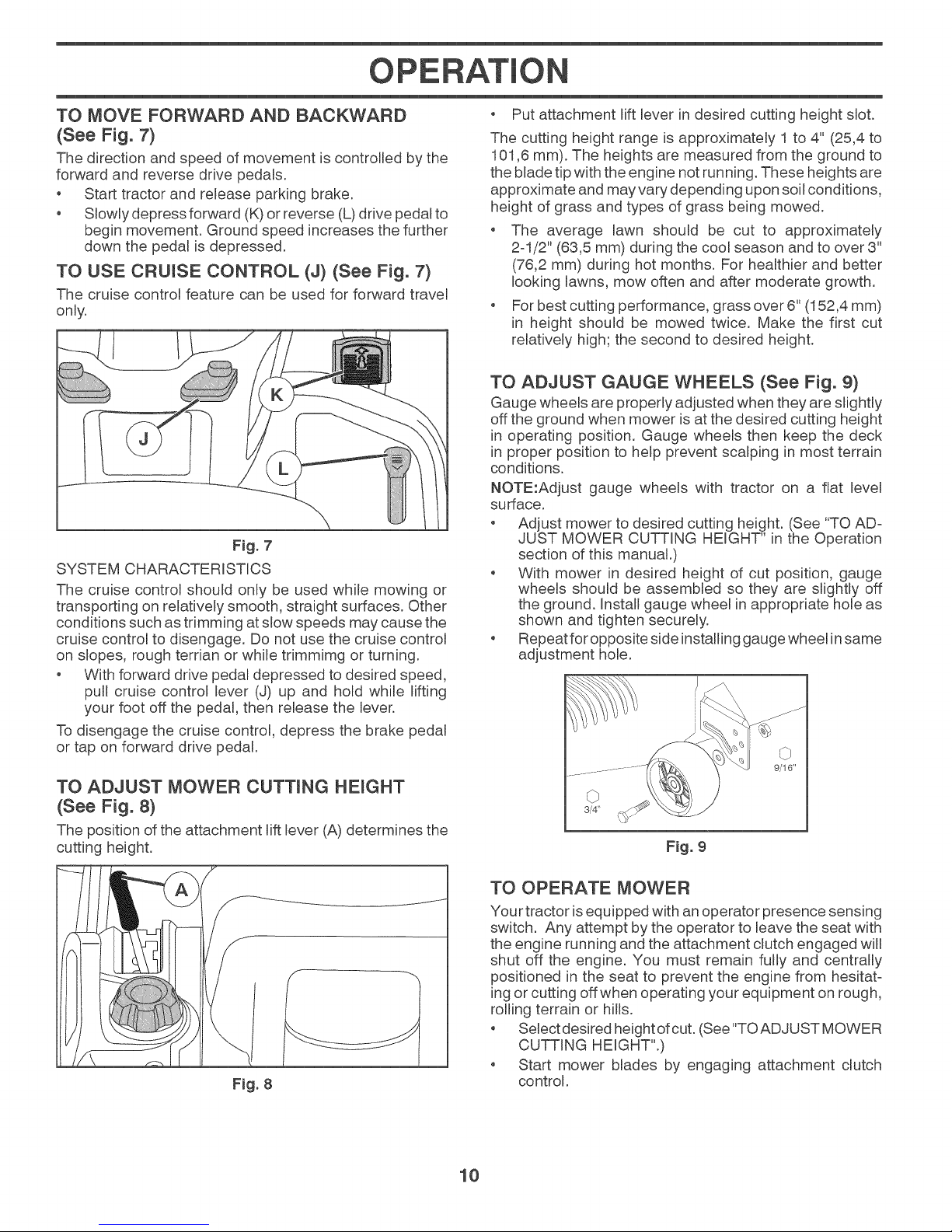
TO MOVE FORWARD AND BACKWARD
(See Fig. 7)
The direction and speed of movement is controlJed by the
forward and reverse drive pedals.
Start tractor and release parking brake.
o Slowly depress forward (K) or reverse (L) drive pedal to
begin movement. Ground speed increases the further
down the pedal is depressed.
TO USE CRUISE CONTROL (J) (See Fig. 7)
The cruise control feature can be used for forward travel
only.
F_g. 7
SYSTEM CHARACTERISTICS
The cruise control should only be used wMle mowing or
transporting on relatively smooth, straight surfaces. Other
conditions such as trimming at slow speeds may cause the
cruise control to disengage. Do not use the cruise control
on slopes, rough tertian or while trimmimg or turning.
With forward drive pedal depressed to desired speed,
pull cruise control lever (J) up and hold while lifting
your foot off the pedal, then release the lever.
To disengage the cruise control, depress the brake pedal
or tap on forward drive pedal.
Put attachment lift lever in desired cutting height slot.
The cutting height range is approximately 1 to 4" (25,4 to
101,6 mm). The heights are measured from the ground to
the blade tip with the engine not running. These heights are
approximate and may vary depending upon soil conditions,
height of grass and types of grass being mowed.
The average lawn should be cut to approximately
2-1/2" (63,5 mm) during the cool season and to over 3"
(76,2 mm) during hot months. For healthier and better
looking lawns, mow often and after moderate growth.
For best cutting performance, grass over 6" (152,4 mm)
in height should be mowed twice. Make the first cut
relatively high; the second to desired height.
TO ADJUST GAUGE WHEELS (See Fig. 9)
Gauge wheeJs are properly adjusted when they are slightly
off the ground when mower is at the desired cutting height
in operating position. Gauge wheels then keep the deck
in proper position to help prevent scalping in most terrain
conditions.
NOTE:Adjust gauge wheels with tractor on a flat level
surface.
Adjust mower to desired cutting height. (See "TO AD-
JUST MOWER CUTTING HEIGHT" in the Operation
section of this manual.)
With mower in desired height of cut position, gauge
wheels should be assembled so they are slightly off
the ground. Install gauge wheel in appropriate hole as
shown and tighten securely.
Repeat for opposite side installing gauge wheel insame
adjustment hole.
TO ADJUST MOWER CUTTING HEIGHT
(See Fig. 8)
The position of the attachment lift lever (A) determines the
cutting height.
Fig. 8
3/4"
Fig. 9
TO OPERATE MOWER
Your tractor isequipped with an operator presence sensing
switch. Any attempt by the operator to leave the seat with
the engine running and the attachment clutch engaged will
shut off the engine. You must remain fully and centrally
positioned in the seat to prevent the engine from hesitat-
ing or cutting off when operating your equipment on rough,
rolling terrain or hills.
, Select desired height ofcut. (See "TOAD JUST MOWER
CUTTING HEIGHT".)
, Start mower blades by engaging attachment clutch
control.
10
OPERATION
TO STOP MOWER BLADES
Disengage attachment clutch control.
Fig. 10
REVERSE OPERATION SYSTEM (ROS)
Your tractor is equipped with a Reverse Operation System
(ROS). Any attempt by the operator to traveminthe reverse
direction with the attachment clutch engaged will shut off
the engine unless ignition key is placed in the ROS "ON"
position.
AI_WARN_NG: Backing up with the attachment clutch en-
gaged while mowing is strongly discouraged. Turning the
ROS "ON", to allow reverse operation with the attachment
clutch engaged, should only be done when the operator
decides it is necessary to reposition the machine with the
attachment engaged. Do not mow in reverse unless
absolutely necessary.
USING THE REVERSE OPERATION SYSTEM -
Only use ifyou are certain no children or other bystanders
will enter the mowing area.
• Depress brake pedal all the way down.
• With engine running, turn ignition key counterclockwise
to ROS "ON" position.
• Look down and behind before and while backing.
• Slowly depress reverse drive pedal to start movement.
• When use of the ROS is no longer needed, turn the
ignition key clockwise to engine "ON" position.
TO OPERATE ON HILLS
1_ CAUTION: Do not drive up or down
Choose the slowest speed before starting up or down
hilJs.
o Avoid stopping or changing speed on hills.
If stopping is absolutemynecessary, push brake pedal
quickly to brake position and engage parking brake.
Torestart movement, slowly release parking brake and
brake pedal.
Slowly depress appropriate drive pedal to slowest set-
ting.
o Make all turns slowly.
hills with slopes greater than 15° and
do not drive across any slope.
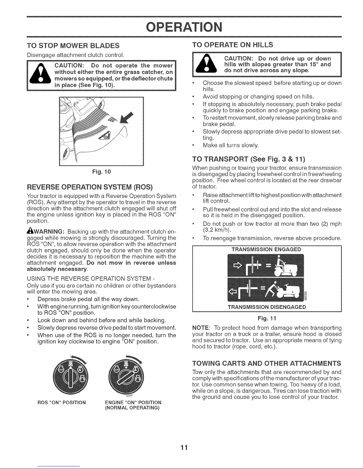
TO TRANSPORT (See Fig. 3 & 11)
When pushing or towing your tractor, ensure transmission
is disengaged by placing freewheemcontrol infreewheeming
position. Free wheel control is located at the rear drawbar
of tractor.
Raise attachment lift to highest position with attachment
lift control.
Pull freewheel control out and into the slot and release
so it is held in the disengaged position.
Do not push or tow tractor at more than two (2) mph
(3,2 kmih).
To reengage transmission, reverse above procedure.
TRANSMISSION ENGAGED
Fig. 11
NOTE: To protect hood from damage when transporting
your tractor on a truck or a trailer, ensure hood is closed
and secured to tractor. Use an appropriate means of tying
hood to tractor (rope, cord, etc.).
ROS "ON" POSITtON ENGINE "ON" POSITION
(NORMAL OPERATING)
TOWING CARTS AND OTHER ATTACHMENTS
Tow only the attachments that are recommended by and
comply with specifications of the manufacturer of your trac-
tor. Use common sense when towing. Too heavy of a load,
while on aslope, is dangerous. Tires can lose traction with
the ground and cause you to lose control of your tractor.
11
OPERAT+ON
BEFORE STARTING THE ENGINE
CHECK ENGINE OiL LEVEL
The engine in your tractor has been shipped from the fac-
tory already filled with summer weight oil.
+ Check engine oil with tractor on level ground.
+ Remove oil fill cap/dipstick and wipe clean, reinsert the
dipstick and screw cap tight, wait for a few seconds,
remove and read oil level If necessary, add oil until
"FULL' mark on dipstick is reached. Do not overfill.
+ For cold weather operation you should change oil for
easier starting. (See "OIL VISCOSITY CHART" in the
Maintenance section of this manual.)
+ To change engine oil, see the Maintenance section in
this manual.
ADD GASOLINE
+ Fill fuel tank to bottom of filler neck. Do not overfill.
Use fresh, clean, regular gasoline with a minimum of
87 octane. Do not mix oil with gasoline. Purchase fuel
in quantities that can be used within 30 days to ensure
fuel freshness.
fuel Do not store, spill or use gasoline
CAUTION: Wipe off any spilled oil or
near an open flame,
iMPORTANT: WHEN OPERATING IN TEMPERATURES
BELOW32 °F (0°C), USE FRESH, CLEAN WINTER GRADE
GASOLINE TO HELP ENSURE GOOD COLD WEATHER
STARTING.
TO START ENGINE (See Fig. 3)
The Briggs & Stratton Endurance engine equipped with
your tractor features a Ready-Start automatic choke system
to provide simplified starting in normal conditions. Please
read the following starting instruction carefully.
When starting the engine for the first time or if the engine
has run out of fuel, it will take extra cranking time to move
fuel from the tank to the engine.
, Ensure freewheel control is inthe transmission engaged
position.
, Sit on seat in operating position, depress brake pedal,
and set parking brake.
, Move attachment clutch control to "DISENGAGED"
position.
NORMAL STARTING (32°F/0°C and above)
, Move throttle control to fast position (_) and click into
place.
+ Insert key into ignition and turn key clockwise (_) to
"START" position and release key as soon as engine
starts.
+ When engine starts, the attachments and ground drive
can now be used. If the engine does not accept the
load and shuts off, restart the engine and allow it to
warm up for one minute.
+ Leave throttle control infast position (_) while mowing.
COLD WEATHER STARTING (32°F/0°C and below)
+ Move throttle control beyond fast position into the cold
weather starting position (@).
CAUTION: AIcohom blended fuels (called gasoho_
or us+rig ethano_ or methano0 can attract moisture
wh+eh _eads to separation and formation of acids
dur+ng storage. Acid+c gas can damage the fue_
system of an eng+ne while +n storage. To avoid
engine probmems,the fue_system should be emptied
before storage of 30 days or monger, Dra+n the gas
tank, start the engine and met+trun until the fue_
Hnes and carburetor are empty, Use fresh fue_ next
season, See Storage instructions for add+tionam
informat+on. Never use engine or carburetor c_eaner
products in the fue_tank or permanent damage may
occur, Fue_stabilizer +san acceptable alternat+ve
in re+him+zing the formation of fue_ gum deposits
during storage. Add stab+_izer to gasoline +nfue_
tank or storage conta+ner. A_ways fo+_ow the m+x
ratio found on stabilizer container, Run engine at
_east 10 m+nutes after add+rig stabH+zer to allow the
stab+Hzer to reach the carburetor, Do not empty
the gas tank and carburetor if us+rig fue_ stabilizer.
CAUTION: Do not run starter continuousmyfor more
than fifteen seconds per minute, ffthe engine does
not start after severa_ attempts, wa+ta few minutes
and try aga+n.
+ Insert key into ignition and turn key clockwise to"START"
position and release key as soon as engine starts.
+ When the engine starts, move the throttle control back
to the fast position (,_) to warm-up. The time required
for warm-up will vary from a few seconds to a minute
depending upon conditions and temperature.
+ Leave throttle control infast position (,_) while mowing.
AUTOMATIC TRANSMISSION WARM UP
+ Before driving the unit in cold weather, the transmission
should be warmed up as follows:
+ Ensure the tractor is on level ground.
+ Remeasethe parking brake and let the brake slowly
return to operating position.
+ Allow one minute for transmission to warm up. This
can be done during the engine warm up period.
+ The attachments can also be used during the engine
warm-up period after the transmission has been warmed
up.
12
OPERATION
PURGE TRANSMISSION
iAo o oooovooo0o0ooo,oo0o0o,oo1
To ensure proper operation and performance, it is recom-
mended that the transmission be purged before operating
tractor for the first time. This procedure will remove any
trapped air inside the transmission which may have devel-
oped during shipping of your tractor.
iMPORTANT: SHOULD YOUR TRANSMISSION REQUIRE
REMOVAL FOR SERVICE OR REPLACEMENT, iT SHOULD
BE PURGEDAFTER REINSTALLATIONBEFOREOPERATING
THE TRACTOR.
1. Place tractor safely on a level surface - that is clear
2. Disengage transmission by placing freewheel control
3. Sitting in the tractor seat, start engine. After the en-
i CAUTmON: At any time, during step 4, there
jill) may be movement of the drive wheels.
whee_ _ever whi_e the engine is running.
and open - with engine off and parking brake set.
in disengaged position. (See "TO TRANSPORT" in
this section of manual.)
gine is running, move throttle control to slow position.
Disengage parking brake
MOWING TiPS
* DO NOT use tire chains when the mower housing is
attached to tractor.
o Mower should be properly leveled for best mowing
performance. See "TO LEVEL MOWER HOUSING"
in the Service and Adjustments section of this manual.
* The left hand side of mower should be used for trimming.
* Drive so that clippings are discharged onto the area
that has been cut. Have the cut area to the right of
the tractor. This will result in a more even distribution
of clippings and more uniform cutting.
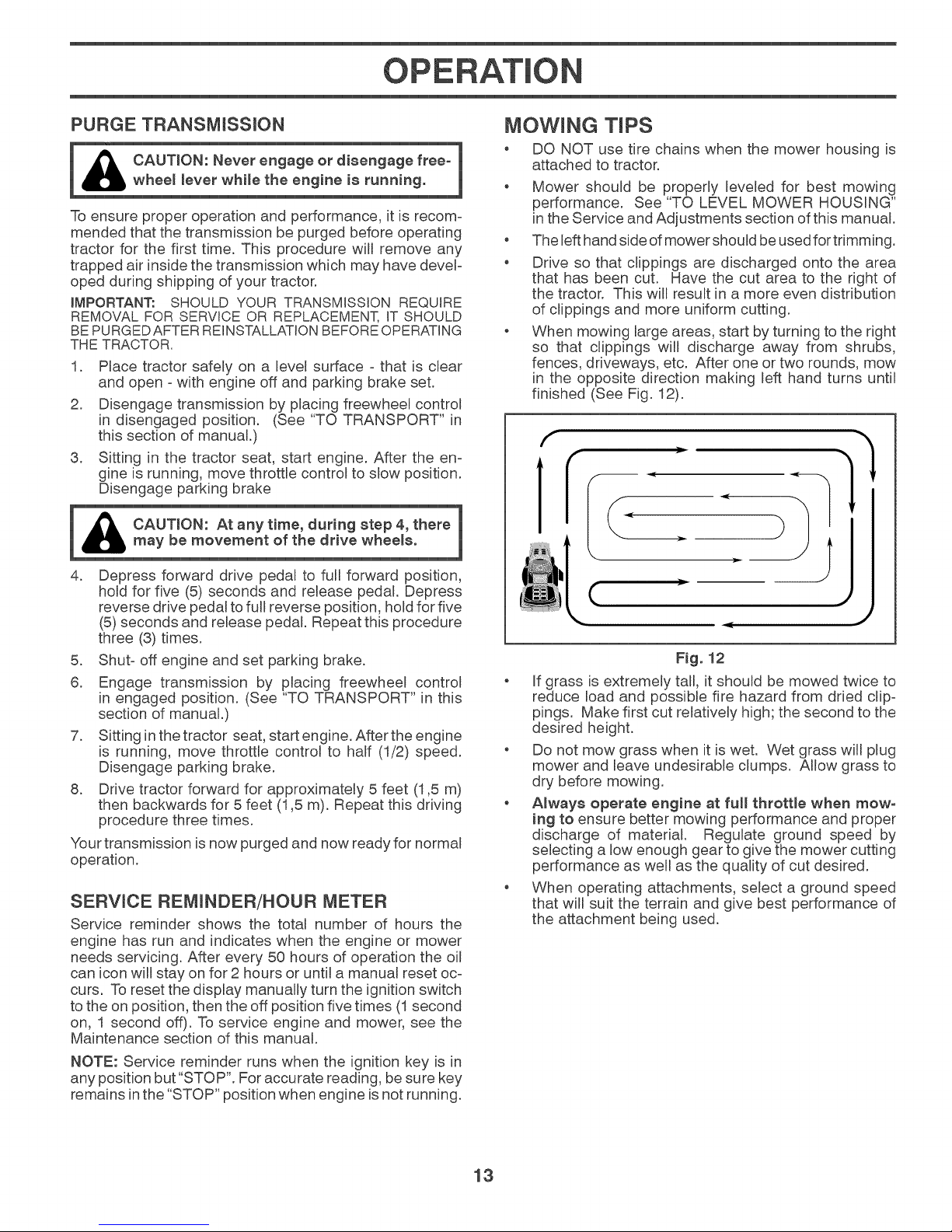
* When mowing large areas, start by turning to the right
so that clippings will discharge away from shrubs,
fences, driveways, etc. After one or two rounds, mow
in the opposite direction making left hand turns until
finished (See Fig. 12).
}1
4. Depress forward drive pedal to full forward position,
hold for five (5) seconds and release pedal. Depress
reverse drive pedal to full reverse position, hold for five
(5) seconds and release pedal. Repeat this procedure
three (3) times.
5. Shut- off engine and set parking brake.
6. Engage transmission by placing freewheel control
in engaged position. (See "TO TRANSPORT" in this
section of manual.)
7. Sitting inthe tractor seat, start engine. After the engine
is running, move throttle control to half (1/2) speed.
Disengage parking brake.
8. Drive tractor forward for approximately 5 feet (1,5 m)
then backwards for 5 feet (1,5 m). Repeat this driving
procedure three times.
Your transmission is now purged and now ready for normal
operation.
SERVICE REMiNDER/HOUR METER
Service reminder shows the total number of hours the
engine has run and indicates when the engine or mower
needs servicing. After every 50 hours of operation the oil
can icon will stay on for 2 hours or until a manual reset oc-
curs. To reset the display manually turn the ignition switch
to the on position, then the off position five times (1second
on, 1 second off). To service engine and mower, see the
Maintenance section of this manual.
NOTE: Service reminder runs when the ignition key is in
any position but "STOP". For accurate reading, besure key
remains inthe "STOP" position when engine is not running.
(
.c ,J
Fig. 12
* If grass is extremely tall, it should be mowed twice to
reduce load and possible fire hazard from dried clip-
pings. Make first cut relatively high; the second to the
desired height.
* Do not mow grass when it is wet. Wet grass will plug
mower and leave undesirable clumps. Allow grass to
dry before mowing.
* Always operate engine at full throttle when mow°
ing to ensure better mowing performance and proper
discharge of material. Regulate ground speed by
selecting a low enough gear to give the mower cutting
performance as well as the quality of cut desired.
* When operating attachments, select a ground speed
that will suit the terrain and give best performance of
the attachment being used.
13
MAINTENANCE
l
Check Brake Operation
Check Tire Pressure
Check Operator Presence & ROS Systems
A Check for Loose Fasteners
C Check/Replace Mower Blades
T Lubrication Chart
0 Check Battery Level
R Clean Battery and Terminals
Clean Debris Off Steering Plate
Check Transaxle Cooling
Check Mower Levelness
Check VoBelts
Check Engine Oil Level
Change Engine Oil (models with oil filter)
Change Engine Oil Imodels without oil filter)
Clean Air RIter
G Clean Air Screen
inspect Muffler/Spark Arrester
N Replace Oil RIter (if equipped)
E Clean Engine Cooling Fins
Replace Spark Plug
Replace Air Filter Paper Cartridge
Replace Fuel Rlter
- Change more often when operating under a heavy load or in high ambient temperatures
2 - Service more often when operating in dirly or dusty conditions
BEFORE
EACH
USE
v'
J
EVERY
8
HOURS
EVERY EVERY EVERY EVERY BEFORE
25 50 100 SEASON STORAGE
HOURS HOURS HOURS
J
J3
J
J
J
v"
_1,2
_1,2
j2
J
3 - Replace blades more often when mowing in sandy soil.
4 - Not required if equipped with maintenance-free ba#ery
v"
J
v'
J
J
v'
v'
J
5 - See Cleaning in Maintenance Section
GENERAL RECOMMENDATIONS
The warranty on this tractor does not cover items that have
been subjected to operator abuse or negligence. Toreceive
fu[[value from the warranty, operator must maintain tractor
as instructed in this manual.
Some adjustments will need to be made periodically to
properly maintain your tractor.
At least once a season, check to see if you should make
any of the adjustments described in the Service and
Adjustments section of this manual.
At least once a year you should replace the spark plug,
clean or replace air filter, and check blades and belts
for wear. A new spark plug and clean air filter assure
proper air-fuel mixture and help your engine run better
and last longer.
BEFORE EACH USE
Check engine oil level.
o Check brake operation.
o Check tire pressure.
o Check operator presence and ROS systems for proper
operation.
Check for loose fasteners.
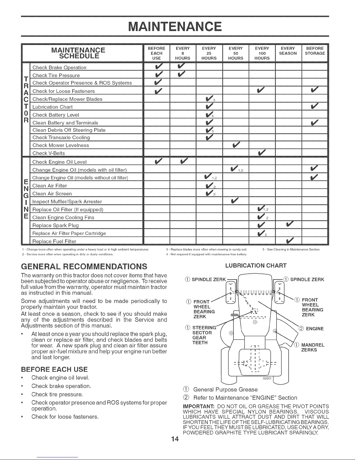
LUBRmCATLON CHART
_-_ SPINDLE ZERK o
_._ FRONT
WHEEL
BEARING
ZERK
SECTOR
GEAR
TEETH
02501
SPINDLE ZERK
(_ General Purpose Grease
Refer to Maintenance "ENGINE" Section
iMPORTANT: DO NOT OiL OR GREASE THE PIVOT POINTS
WHICH HAVE SPECIAL NYLON BEARINGS. VISCOUS
LUBRICANTS WiLL ATTRACT DUST AND DIRT THAT WiLL
SHORTEN THE LiFE OFTHE SELF-LUBRiCATING BEARINGS.
IF YOU FEELTHEY MUST BE LUBRICATED, USE ONLYA DRY,
POWDERED GRAPHITE TYPE LUBRICANT SPARINGLY.
14
FRONT
WHEEL
BEARING
ZERK
ENGINE
MANDREL
ZERKS
M NTENANCE
Always observe safety rules when performing any
maintenance.
BRAKE OPERATION
If tractor requires more than five (5) feet (1,5 m) to stop at
highest speed in highest gear on a level, dry concrete or
paved surface, then brake must be checked and adjusted.
(See "TO CHECK BRAKE" inthe Service and Adjustments
section of this manual.)
T_RES
* Maintain proper air pressure in all tires. (See the sides
of tires for proper PSI.)
* Keep tires free of gasoline, oil, or insect control
chemicals which can harm rubber.
o Avoid stumps, stones, deep ruts, sharp objects and
other hazards that may cause tire damage.
NOTE: To seal tire punctures and prevent flat tires due
to slow leaks, tire sealant may be purchased from your
local parts dealer. Tire sealant also prevents tire dry rot
and corrosion.
OPERATOR PRESENCE SYSTEM AND REVERSE
OPERATION SYSTEM (ROS) (See Fig. 13)
Be sure operator presence and reverse operation systems
are working properly. If your tractor does not function as
described, repair the problem immediately.
* The engine should not start unless the brake pedal is
fully depressed, and the attachment clutch control is
in the disengaged position.
CHECK OPERATOR PRESENCE SYSTEM
* When the engine isrunning, any attempt by the operator
to leave the seat without first setting the parking brake
should shut off the engine.
* When the engine is running and the attachment clutch
is engaged, any attempt by the operator to leave the
seat should shut off the engine.
* The attachment clutch should never operate unless
the operator is in the seat.
CHECK REVERSE OPERATION (ROS) SYSTEM
* When the engine is running with the ignition switch in
the engine "ON" position and the attachment clutch
engaged, any attempt by the operator to shift into
reverse should shut off the engine.
* When the engine is running with the ignition switch
in the ROS "ON" position and the attachment clutch
engaged, any attempt by the operator to shift into
reverse should NOT shut off the engine.
ROS "ON"
POSITION
ENGINE "ON" POSJT_ON
(NORMAL OPERATING}
Fig. 13
BLADE CARE
For best results mower blades must be kept sharp. Replace
bent or damaged blades.
& AUTION: Use onlya replacement blade ap-
proved bythe manufacturer of your tractor.
Using a blade not approved by the manu-
facturer of your tractor kshazardous, could
damage your tractor and void your warranty.
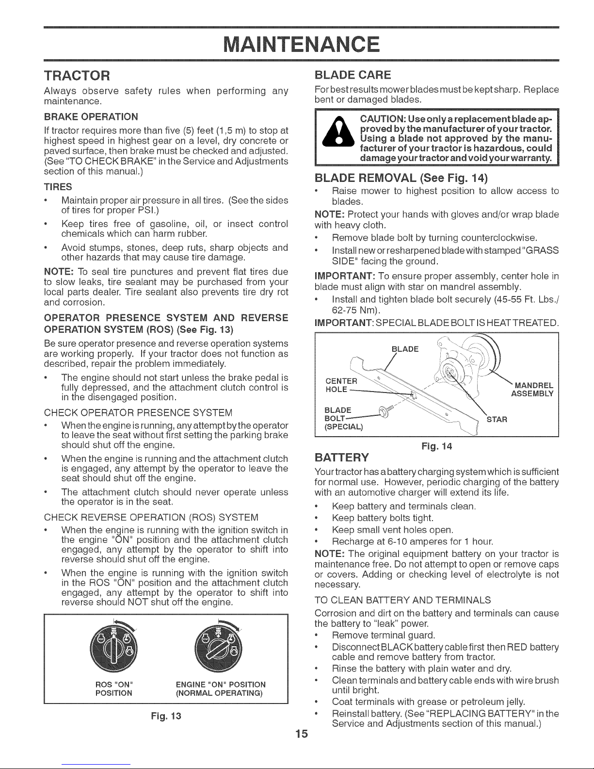
BLADE REMOVAL (See Fig. 14)
o Raise mower to highest position to allow access to
blades.
NOTE: Protect your hands with gloves and/or wrap blade
with heavy cloth.
o Remove blade bolt by turning counterclockwise.
o Install new or resharpened blade withstamped "GRASS
SIDE" facing the ground.
LMPORTANT: To ensure proper assembly, center hole in
blade must align with star on mandrel assembly.
o Install and tighten blade bolt securely (45%5 Ft. Lbs./
62-75 Nm).
LMPORTANT: SPECIAL BLADE BOLT ISHEATTREATED.
BLADE
CENTER
ASSEMBLY
(SPECIAL)
F_g. 14
Your tractor has a battery charging system which issufficient
for normal use. However, periodic charging of the battery
with an automotive charger will extend its life.
* Keep battery and terminals clean.
* Keep battery bolts tight.
* Keep small vent holes open.
* Recharge at 6-10 amperes for 1 hour.
NOTE: The original equipment battery on your tractor is
maintenance free. Do not attempt to open or remove caps
or covers. Adding or checking level of electrolyte is not
necessary.
TO CLEAN BATTERY AND TERMINALS
Corrosion and dirt on the battery and terminals can cause
the battery to "leak" power.
* Remove terminal guard.
* DisconnectBLACKbatterycablefirst then RED battery
cable and remove battery from tractor.
* Rinse the battery with plain water and dry.
* Clean terminals and battery cable ends with wire brush
until bright.
* Coat terminals with grease or petroleum jelly.
* Reinstall battery. (See "REPLACING BATTERY" in the
Service and Adjustments section of this manual.)
15
STAR
MAINTENANCE
TRANSAXLE MAINTENANCE
The transmission fan and cooling fins should be kept clean
to ensure proper cooling.
Do not attempt to clean fan or transmission while engine
is running or while the transmission is hot. To prevent pos-
sible damage to seals, do not use high pressure water or
steam to clean transmission.
Inspect cooling fan to be sure fan blades are intact and
clean.
o Inspect cooling fins for dirt, grass clippings and other
materials. To prevent damage to seals, do not use com-
pressed airor high pressure sprayer to clean cooling fins.
TRANSAXLE PUMP FLUID
The transaxle was sealed at the factory and fluid mainte-
nance is not required for the life of the transaxle. Should
the transaxle ever leak or require servicing, contact your
nearest authorized service center/department.
Check V-belts for deterioration and wear after 100 hours
of operation and replace if necessary. The belts are not
adjustable. Replace belts if they begin to slip from wear.
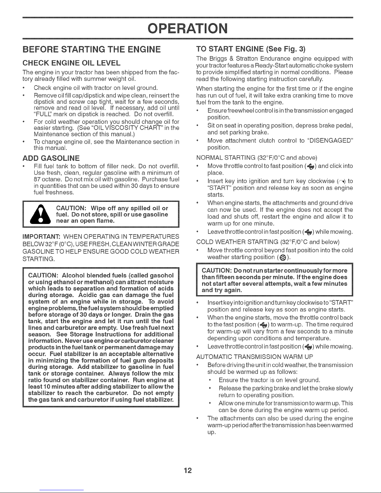
Only use high quality detergent oil rated with API service
classification SG-SL. Select the oil's SAE viscosity grade
according to your expected operating temperature.
SAE VISCOSITY GRADES
F -20 0 30 32 40 60 80 100
C "dO "2'0 -1; ; 1'0 ;0 dO
TEMPERATURE RANGE ANTiCiPATED BEFORE NEXT OIL CHANGE
Fig. 15
NOTE: Although multi-viscosity oils (5W30, 10W30 etc.)
improve starting in cold weather, they will result in increased
oil consumption when used above 32°F/0°C. Check your
engine oil level more frequently to avoid possible engine
damage from running low on oil.
Change the oil after every 50 hours of operation or at least
once a year ifthe tractor is not used for 50 hours in one year.
Check the crankcase oil level before starting the engine
and after each eight (8) hours of operation. Tighten oil fill
cap/dipstick securely each time you check the oil level.
TO CHANGE ENGINE OiL (See Fig. 15 - 17)
Determine temperature range expected before oil change.
All oil must meet APi service classification SG-SL
Be sure tractor is on level surface.
o Oil will drain more freely when warm.
Catch oil in a suitable container.
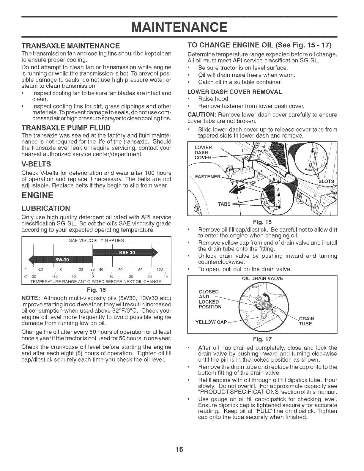
LOWER DASH COVER REMOVAL
Raise hood.
Remove fastener from lower dash cover.
CAUTION: Remove lower dash cover carefully to ensure
cover tabs are not broken.
Slide lower dash cover up to release cover tabs from
tapered slots in lower dash and remove.
LOWER
DASH
COVER
TABS
F_g. 15
Remove oil fill cap/dipstick. Be careful not to allow dirt
to enter the engine when changing oil.
Remove yellow cap from end of drain valve and install
the drain tube onto the fitting.
Unlock drain valve by pushing inward and turning
counterclockwise.
To open, pull out on the drain valve.
OIL DRAIN VALVE
LOCKE
Fig. 17
, After oil has drained completely, close and lock the
drain valve by pushing inward and turning clockwise
until the pin is in the locked position as shown.
Remove the drain tube and replace the cap onto to the
bottom fitting of the drain valve.
Refill engine with oil through oil fill dipstick tube. Pour
slowly. Do not overfill. For approximate capacity see
"PRODUCT SPECiFICATiONS" section of this manual.
Use gauge on oil fiil cap/dipstick for checking level.
Ensure dipstick cap is tightened securely for accurate
reading. Keep oil at "FULL' line on dipstick. Tighten
cap onto the tube securely when finished.
16
MA+NTENANCE
ENGINE OIL FILTER
Replace the engine oil filter every season or every other oil
change ifthetractor is used more than 100 hours inone year.
NOTE: If needed, remove lower dash covers using steps
from "Lower dash cover removal" section of this manual.
AiR FILTER
Your engine will not run properly using a dirty air filter. Ser-
vice air cleaner more often under dusty conditions.
CLEAN AIR SCREEN
The air screen is over the air intake blower located on top
of engine. The air screen must be kept free of dirt and
chaff to prevent engine damage from overheating. Clean
with a wire brush or compressed air to remove dirt and
stubborn dried gum fibers.
ENGINE COOLING SYSTEM
To ensure proper cooling, make sure the grass screen,
cooling fins, and other external surfaces of the engine are
kept clean at all times.
Every 100 hours of operation (more often under extremely
dusty, dirtyconditions), remove the blower housing and other
cooling shrouds. Clean the cooling fins and external surfaces
as necessary. Ensure the cooling shrouds are reinstalled.
NOTE: Operating the engine with a blocked grass screen,
dirty orplugged cooling fins, and/or cooling shrouds removed
will cause engine damage due to overheating.
Inspect and replace corroded muffler and spark arrester (if
equipped) as it could create a fire hazard and/or damage.
SPARK PLUGS
Replace spark plugs at the beginning of each mowing
season or after every 100 hours of operation, whichever
occurs first. Spark plug type and gap setting are shown
in "PRODUCT SPECIFICATIONS" section of this manual.
CLEANING (See Fig. 19)
+ Clean engine, battery, seat, finish, etc. of all foreign
matter.
+ Clean debris from steering plate. Debris can restrict
clutch/brake pedal shaft movement, causing belt slip
and loss of drive.
,_ CAUTION: Avoid all pinch points and
movable parts.
+_CLUTCH/BRAKE PEDAL0
CLEAN
/
TOP SIDE
//
STEERING SYSTEM, DASH, FENDER AND MOWER NOT SHOWN
Fig. 19
+ Keep finished surfaces and wheels free of all gasoline,
oil, etc.
+ Protect painted surfaces with automotive type wax.
Except for the washout port (if equipped), we do not
recommend using a garden hose or pressure washer to
clean the outside of your tractor unless the engine and
transmission are covered to keep water out. Water in
engine or transmission will shorten the useful life of your
tractor. Use compressed air or a leaf blower to remove
grass, leaves and trash from outside tractor and mower.
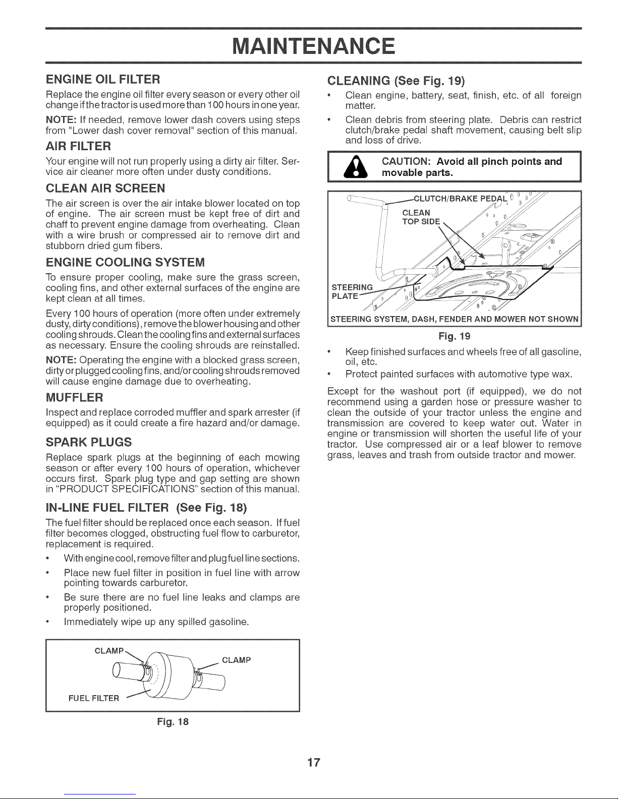
IN-LINE FUEL FILTER (See Fig. 18)
The fuel filter should be replaced once each season. Iffuem
filter becomes clogged, obstructing fuel flow to carburetor,
replacement is required.
+ With engine cool, remove filter and plug fuet linesections.
+ Place new fuel filter in position in fuel line with arrow
pointing towards carburetor.
+ Be sure there are no fuel line leaks and clamps are
properly positioned.
+ Immediately wipe up any spilled gasoline.
OLA
FUEL FILTER
Fig. 18
CLAMP
17
M NTENANCE
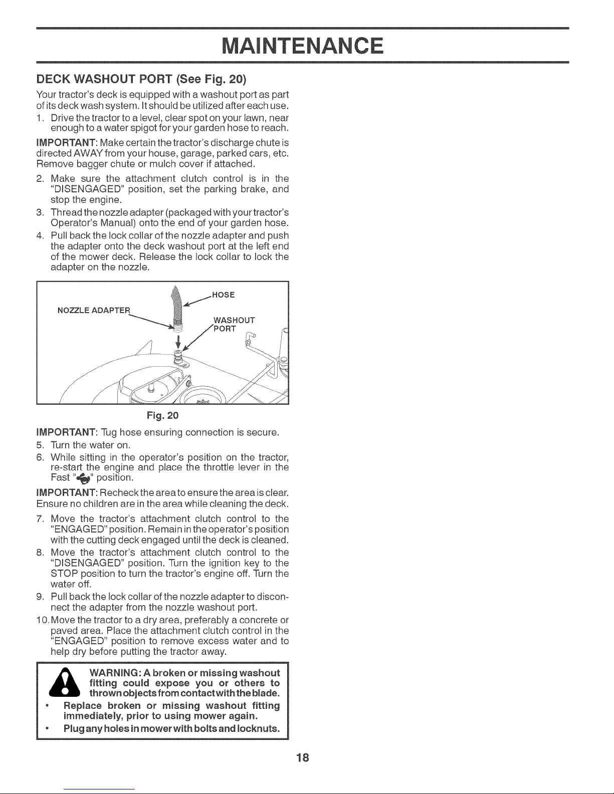
DECK WASHOUT PORT (See Fig. 20)
Your tractor's deck is equipped with a washout port as part
of its deck wash system. It should be utilized after each use.
1. Drive the tractor to alevel, clear spot onyour lawn, near
enough to awater spigot for your garden hose to reach.
LMPORTANT: Make certain the tractor's discharge chute is
directed AWAY from your house, garage, parked cars, etc.
Remove bagger chute or mulch cover if attached.
2. Make sure the attachment clutch control is in the
"DISENGAGED" position, set the parking brake, and
stop the engine.
3. Thread the nozzle adapter (packaged with your tractor's
Operator's Manual) onto the end of your garden hose.
4. Pull back the lock collar of the nozzle adapter and push
the adapter onto the deck washout port at the left end
of the mower deck. Release the lock collar to lock the
adapter on the nozzle.
Fig. 20
LMPORTANT: q%ghose ensuring connection is secure.
5. Turn the water on.
6. While sitting in the operator's position on the tractor,
re-start the engine and place the throttle lever in the
Fast "_" position.
LMPORTANT: Recheck the area to ensure the area isclear.
Ensure no children are inthe area while cleaning the deck.
7. Move the tractor's attachment clutch control to the
"ENGAGED" position. Remain inthe operator's position
with the cutting deck engaged until the deck is cleaned.
8. Move the tractor's attachment clutch control to the
"DISENGAGED" position. Turn the ignition key to the
STOP position to turn the tractor's engine off. Turn the
water off.
9. Pull back the lock collar of the nozzle adapter to discon-
nect the adapter from the nozzle washout port.
10. Move the tractor to a dry area, preferably a concrete or
paved area. Place the attachment clutch control in the
"ENGAGED" position to remove excess water and to
help dry before putting the tractor away.
fitting toured expose you or others to
WARNING: A broken or missing washout
thrown objects from contact with the blade.
, Replace broken or missing washout fitting
immediately, prior to using mower again.
o Plug any homesin mower with borersand Iocknuts.
18
I A J
° Depress brake pedal fully and set parking brake.
WARNING: TO AVOmD SERIOUS iNJURY, BEFORE PERFORMING ANY SERVICE OR ADJUSTMENTS:
° P_aee attachment clutch in "DmSENGAGED" position.
° Turn ignition key to "STOP" and remove key.
" Make sure the blades and all moving parts have completely stopped.
" Disconnect spark plug wire from spark plug and place wire where it cannot come incontact with plug.
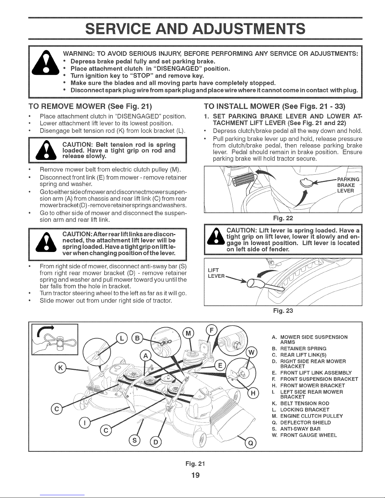
TO REMOVE MOWER (See Fig. 21)
Place attachment clutch in "DISENGAGED" position.
Lower attachment lift lever to its lowest position.
Disengage berettension rod (K) from lock bracket (L).
1 _ CAUT,ON: Belt tensionrodisspring 1
U re_ease s_ow_y.
o Remove mower beretfrom electric clutch pulley (M).
Disconnect front link (E)from mower =remove retainer
spring and washer.
Goto eitherside ofmower anddisconnectmowersuspen=
sion arm (A) from chassis and rear lift link (0) from rear
mower bracket (D)=remove retainersprings andwashers.
Go to other side of mower and disconnect the suspen=
sion arm and rear lift link.
&
From right side of mower, disconnect anti-sway bar (S)
from right rear mower bracket (D) = remove retainer
spring and washer and pull mower toward you until the
bar falls from the hole in bracket.
Turn tractor steering wheel to the left as far as itwill go.
Slide mower out from under right side of tractor.
loaded. Have a tight grip on rodand |
CAUTNON:After rear lift _inksare discon-
nected, the attachment lift _ever will be
spring _oaded. Have aright grip on Hft _e-
vet when changing position of the lever.
TO iNSTALL MOWER (See Figs. 21 - 33)
1. SET PARKING BRAKE LEVER AND LOWER ATo
TACHMENT LiFT LEVER (See Fig. 21 and 22)
o Depress clutch/brake pedal all the way down and hold.
o Pull parking brake lever up and hold, release pressure
from clutch/brake pedal, then remease parking brake
lever. Pedal should remain in brake position. Ensure
parking brake will hold tractor secure.
Fig. 22
on meftside of fender.
UFT
Fig. 23
Ao MOWER SiDE SUSPENSION
ARMS
Bo RETAINER SPRING
C. REAR LiFT LINK(S)
D° RIGHT SiDE REAR MOWER
BRACKET
E. FRONT LiFT LiNK ASSEMBLY
E FRONT SUSPENSION BRACKET
Ho FRONT MOWER BRACKET
L LEFTSIDE REAR MOWER
BRACKET
K° BELT TENSION ROD
L° LOCKaNG BRACKET
M° ENGINE CLUTCH PULLEY
Q° DEFLECTOR SHIELD
S. ANTra-SWAY BAR
Wo FRONT GAUGE WHEEL
[
Fig. 21
19
EA A
2_
ASSEMBLE FRONT GAUGE WHEEL (W) TO FRONT
OF MOWER (See Fig. 24)
H. FRONT MOWER
BRACKET
Wo FRONT GAUGE
WHEEL
X. SHOULDER
BOLT
Y. 1-1/4 CoD.
WASHER
Z° 3/8-16 LOCKNUT
Fig. 24
3_
TURN STEERING WHEEL
LEFT AND POSLTmON
MOWER (See Fig. 25)
Turn steering wheel to the left as far as it will go and
position mower on right side of tractor with deflector
shield (Q) to the right.
FRONT
TRANSAXLE
Qo DEFLECTOR
SHIELD
5_
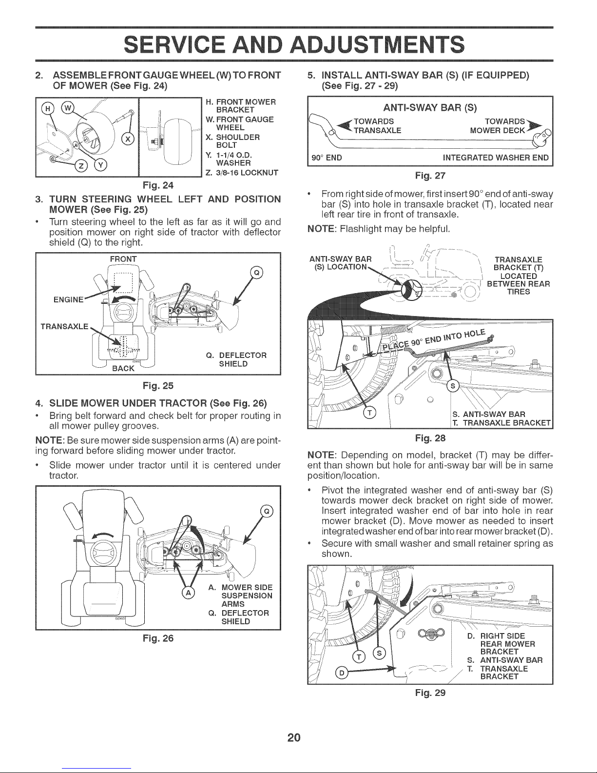
iNSTALL ANTI-SWAY BAR (S) OF EQUIPPED)
(See Fig. 27 - 29)
i
TOWARDS TOWARDS b.
90° END INTEGRATED WASHER END
ANTbSWAY BAR (S)
TRANSAXLE MOWER DECK p'-
F_g.27
From right side of mower, first insert 90 °end of anti-sway
bar (S) into hole in transaxle bracket (T), located near
left rear tire in front of transaxle.
NOTE: Flashlight may be helpful.
ANTI-SWAY BAR /'Y
(S) ...........................................................; LOCATED
,_,,,,_,,-, TRANSAXLE
_/r> ..............................
BRACKET (1")
..................:> ....... BETWEEN REAR
/'-','i TIRES
F_g. 25
4. SUDE MOWER UNDER TRACTOR (See Fig. 26)
o Bring belt forward and check belt for proper routing in
all mower pulley grooves.
NOTE: Be sure mower side suspension arms (A) are point-
ing forward before sliding mower under tractor.
o Slide mower under tractor until it is centered under
tractor.
Ao MOWER SIDE
SUSPENSION
ARMS
Q. DEFLECTOR
SHIELD
Fig. 26
B. ANTI-SWAY BAR
T. TRANSAXLE BRACKET
Fig. 28
NOTE: Depending on model, bracket (T) may be differ-
ent than shown but hole for anti-sway bar will be in same
position/location.
Pivot the integrated washer end of anti-sway bar (S)
towards mower deck bracket on right side of mower.
Insert integrated washer end of bar into hole in rear
mower bracket (D). Move mower as needed to insert
integrated washer end of bar into rear mower bracket (D).
Secure with small washer and small retainer spring as
shown.
Fig. 29
20
I A J
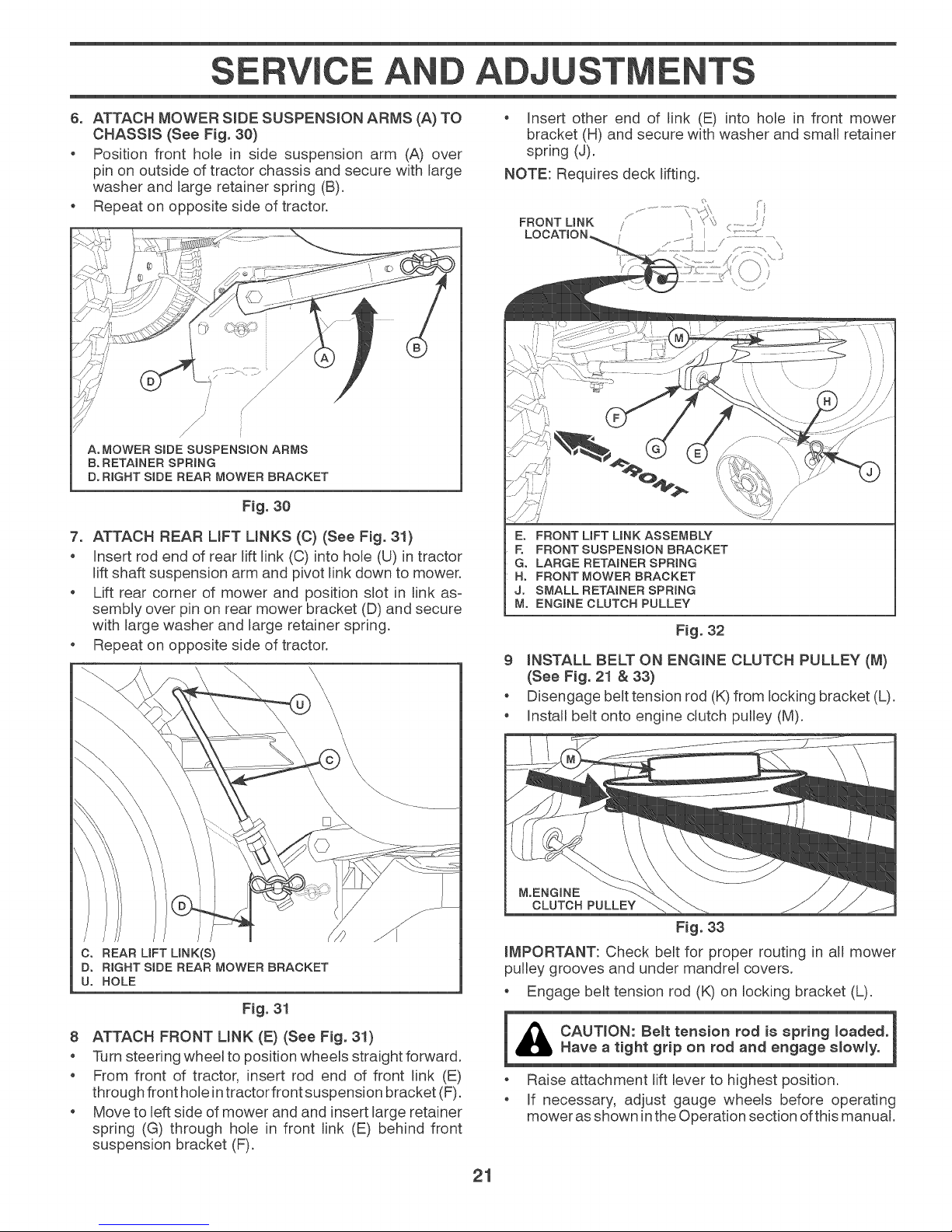
6. ATTACH MOWER SIDE SUSPENSION ARMS (A) TO
CHASSIS (See Fig. 30)
o Position front hole in side suspension arm (A) over
pin on outside of tractor chassis and secure with large
washer and large retainer spring (B).
Repeat on opposite side of tractor.
; /
/ /
/
/
A. MOWER SiDE SUSPENSION ARMS
B. RETAINER SPRING
D° RIGHT SiDE REAR MOWER BRACKET
/
;/
Fig. 30
7. ATTACH REAR LIFT LINKS (C) (See Fig. 31)
Insert rod end of rear lift link (C) into hole (U) in tractor
lift shaft suspension arm and pivot link down to mower.
Lift rear corner of mower and position slot in link as-
sembly over pin on rear mower bracket (D) and secure
with large washer and large retainer spring.
Repeat on opposite side of tractor.
Insert other end of link (E) into hole in front mower
bracket (H) and secure with washer and small retainer
spring (J).
NOTE: Requires deck lifting.
E° FRONT UFT UNK ASSEMBLY
E FRONT SUSPENSION BRACKET
G. LARGE RETAINER SPRING
H° FRONT MOWER BRACKET
J° SMALL RETAINER SPRING
M° ENGINE CLUTCH PULLEY
Fig. 32
9 LNSTALL BELT ON ENGmNECLUTCH PULLEY (M)
(See Fig. 21 & 33}
o Disengage belt tension rod (K)from locking bracket (L).
o InstalJbelt onto engine clutch pulley (M).
C. REAR LIFT LINK(S)
Do RIGHT SiDE REAR MOWER BRACKET
U° HOLE
Fig. 31
8 ATTACH FRONT MNK (E) (See Fig. 31)
Turn steering wheeJ to position wheels straight forward.
o From front of tractor, insert rod end of front link (E)
through front hole in tractor front suspension bracket (F).
Move to left side of mower and and insert large retainer
spring (G) through hole in front link (E) behind front
suspension bracket (F).
M.ENGINE
CLUTCH PULLEY
Fig. 33
iMPORTANT: Check belt for proper routing in alJmower
pulley grooves and under mandrel covers.
Engage belt tension rod (K) on locking bracket (L).
i CAUTmON: Be_t tension rod is spring loaded. 1
_IL Have a tight grip on rod and engage slowly.
Raise attachment lift lever to highest position.
If necessary, adjust gauge wheels before operating
mower asshown inthe Operation section of this manual.
21
 Loading...