

Page 1
WaterWorks TM
Undersink Reverse Osmosis
HOME DRINKING WATER SYSTEM
Model RO 2000
Installation
Operation
Maintenance
Repair Parts
IF YOU HAVE QUESTIONS WHEN
INSTALLING, OPERATING
AND MAINTAINING YOUR REVERSE
OSMOSIS SYSTEM...
CALL TOLL FREE
1-800-86 WATER
System Tested and Certified to
ANSI/NSF Standard 58. See
performance data sheet for details,
Manufactured by EcoWater Systems, Inc, PO BOX 64420, ST. PAUL, MN 55164 Part No. 721 4105 (10/99)
Page 2
- TABLE OF CONTENTS -
Safety Guides ................................................ 2-3
What Your Home Drinking Water System Will Do ..................... 3
Things To Check Before You Start To Install ....................... 4-5
How To Install Your Home Drinking Water System ................. 5-11
How Your Home Drinking Water System Works .................. 11-12
Care Of Your Home Drinking Water System ..................... 13-16
Dimensions And Specifications ................................... 17
Repair Parts ............................................... 18-19
Remote Locations For The RO ..................................... 20
-WARRANTY-
FULL WARRANTY ON DELUXE REVERSE OSMOSIS DRINKING WATER SYSTEM
(except battery, filter, filter cartridge or membrane)
For one year from the date of purchase, when this deluxe reverse osmosis drinking water system
is installed and maintained in accordance with our instructions, Sears will repair, free of charge, de-
fects in material and workmanship, except for disposable battery, filters, cartridges and membranes.
TO OBTAIN WARRANTY SERVICE, SIMPLY CONTACT THE NEAREST SEARS SERVICE
CENTER THROUGHOUT THE UNITED STATES. This warranty applies only while this product
is in use in the United States.
This warranty gives you specific legal rights, and you may have other rights which vary from state
to state.
Sears, Roebuck and Co., D/817 WA, Hoffman Estates, IL 60179
SEARS INSTALLATION POLICY
All installation labor arranged by Sears shall be
performed in a neat, workmanlike manner in
accordance with generally accepted trade prac-
tices. Further, all installations shall comply with all
local laws, codes, regulations, and ordinances.
Customer shall also be protected, during installa-
tion, by insurance relating to Property Damage,
Workman's Compensation and Public Liability.
SEARS INSTALLATION WARRANTY
In addition to any warranty extended to you on
the WaterWorks merchandise involved, which
warranty becomes effective the date the mer-
chandise is installed, should the workmanship of
any Sears arranged installation prove faulty
within one year, Sears will, upon notice from you,
cause such faults to be corrected at no additional
cost to you.
- SAFETY GUIDES -
_' Read all steps, guides and rules carefully
before installing and using your Home Drink-
ing Water System. Follow all steps exactly to
correctly install. Reading this book will also
help you to get all the benefits from your Home
Drinking Water System.
DO NOT ATTEMPT TO USE THIS PROD-
UCT TO MAKE SAFE DRINKING WATER
FROM NON-POTABLE WATER SOURCES.
2
Page 3
- SAFETY GUIDES -
DO NOT USE THE SYSTEM ON
MICROBIOLOGICALLY UNSAFE WATER,
OR WATER OF UNKNOWN QUALITY
WITHOUT ADEQUATE DISINFECTION
BEFORE OR AFTER THE SYSTEM.
Systems certified for cyst reduction may
be used on disinfected water that may
contain filterable cysts.
CHECK WITH YOUR LOCAL PUBLIC
WORKS DEPARTMENT FOR PLUMBING
AND SANITATION CODES. YOU MUST
FOLLOW THEIR GUIDES AS YOU INSTALL
THE SYSTEM. FOLLOW YOUR LOCAL
CODES IF THEY DIFFER WITH GUIDES IN
THIS MANUAL.
house water pressure is over the maximum,
install a pressure reducing valve in the water
supply to the Home Drinking Water System.
Do not install the Home Drinking Water System
outside, or in extreme hot or cold temp-
eratures. Temperature of the water supply to
the Home Drinking Water System must be be-
tween 40OF (minimum) and 100OF (maximum).
See the specification table on page 17. DO
NOT INSTALL ON HOT WATER.
Read the other limits (pH, hardness, etc.) on
page 17 and be sure your water supply con-
forms. Please read WATER SUPPLY, page 4.
The Home Drinking Water System works on
water pressure of 40 psi (minimum) to 125 psi
(maximum). See the table on page 17. If your
- WHAT YOUR HOME DRINKING WATER SYSTEM WILL DO -
Your Home Drinking Water System is a REVERSE
OSMOSIS (RO) water treating unit. It uses
household water pressure to reverse a natural
physical process called osmosis. Water, under
pressure, is forced through a semi-permeable mem-
brane where minerals and impurities are screen-
ed out and sent down the drain with the waste
water. These minerals and impurities are measured
as total dissolved solids (TDS).
The system includes replaceable pre and postfilter
sediment-carbon cartridges. The prefilter removes
sand, dirt, rust particles and other sediments. It also
takes chlorine out of the feed water. The postfilter
removes any remaining tastes and/or odors just
before water is taken from the system faucet. The
storage area holds almost 1 gallon of RO product
water for your needs.
The undersink system connects to a house COLD
water pipe for a water supply. An automatic shutoff
valve prevents water waste when the storage area
is full and the faucet is closed.
The drinking water system gives you a continuous
supply of sparkling clear, delicious water for drink-
ing and cooking. Foods will look better and taste
better too. The system eliminates the need to buy
bottled water. Instead, it puts high quality water right
at your fingertips.
NOTE: A product data sheet is included, and also
available from Sears. The data sheet lists what this
RO system will remove (or reduce) from the water.
ELECTRONIC MONITOR
The electronic model has 2 water quality sensors,
located in the electronic box. Indicator lights on the
faucet base work with the sensors, or probes, to
show you when water quality is good, and when the
system needs servicing.
As you take water from the RO faucet, a flashing
green light means the system is giving you high
quality RO water. Over a period of time, the RO
membrane, prefilter cartridge and postfilter begin
to lose efficiency. Flashing amber lights (see pages
12, 13 and 14) tell you when to service the RO mem-
brane and filters.
3
Page 4
- THINGS TO CHECK BEFORE YOU START TO INSTALL -
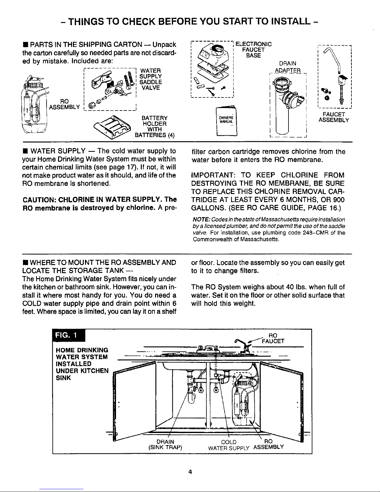
• PARTS IN THE SHIPPING CARTON -- Unpack
the carton carefully so needed parts are not discard-
ed by mistake. Included are:
_ _ WATER
(_ _ _ t SUPPLY
_,/_1 _b')_tl SADDLE
VALVE
_,,_ --.
RO
, I ASSEMBLY _ .t
_ BATTERY
HOLDER
_ WITH
BATTERIES (4)
I
ELECTRONIC
FAUCET
BASE
DRAIN
ADAPTER
£
FAUCET
ASSEMBLY
• WATER SUPPLY -- The cold water supply to
your Home Drinking Water System must be within
certain chemical limits (see page 17). If not, it will
not make product water as it should, and life of the
RO membrane is shortened.
CAUTION: CHLORINE IN WATER SUPPLY. The
RO membrane is destroyed by chlorine. A pre-
filter carbon cartridge removes chlorine from the
water before it enters the RO membrane.
IMPORTANT: TO KEEP CHLORINE FROM
DESTROYING THE RO MEMBRANE, BE SURE
TO REPLACE THIS CHLORINE REMOVAL CAR-
TRIDGE AT LEAST EVERY 6 MONTHS, OR 900
GALLONS. (SEE RO CARE GUIDE, PAGE 16.)
NOTE: Codes in thestate of Massachusetts require installation
by a licensed plumber, and do not permit the use of the saddle
valve. For installation, use plumbing code 248-CMR of the
Commonwea]th of Massachusetts.
• WHERE TO MOUNT THE RO ASSEMBLY AND
LOCATE THE STORAGE TANK --
The Home Drinking Water System fits nicely under
the kitchen or bathroom sink. However, you can in-
stall it where most handy for you. You do need a
COLD water supply pipe and drain point within 6
feet. Where space is limited, you can lay iton a shelf
or floor. Locate the assembly so you can easily get
to it to change filters.
The RO System weighs about 40 Ibs. when full of
water. Set it on the floor or other solid surface that
will hold this weight.
RO
/FAUCET
HOME DRINKING
WATER SYSTEM
INSTALLED
UNDER KITCHEN
SINK
DRAIN COLD RO
(SINK TRAP) WATER SUPPLY ASSEMBLY
Page 5
- THINGS TO CHECK BEFORE YOU START TO INSTALL -
REMOTE LOCATION -- You can install the RO
assembly or water supply saddle valve in another
place away from the RO faucet (please see page
2O).
• REPLACING ANOTHER RO SYSTEM -- We
suggest you remove all parts of another RO system,
and use everything included with your new RO
system.
- TOOLS AND MATERIALS YOU WILL NEED -
==9/16" open end, or adjustable wrench
• standard pliers, and larger adjustable jaw pliers
or pipe wrench
• slotted and Phillips head screwdrivers
• plumbers putty
• pipe joint compound (thread seal) or Teflon
tape, approved for use on potable water sup-
plies
• hand or battery powered drill with 1/8" bit (if
needed for the cold water supply valve, page 6)
• electric drill and bits, if hole is needed for the
RO faucet, page 7
CAUTION: TO AVOID DAMAGING A SINK
BEYOND REPAIR, CONSULT A QUALIFIED
PLUMBER OR INSTALLER FOR GUIDES
BEFORE DRILLING HOLES IN PORCELAIN OR
STAINLESS STEEL
- 5 STEPS TO INSTALL THE SYSTEM -
STEP 1 - INSTALL THE COLD WATER SUPPLY SADDLE VALVE, PAGE 6.
STEP 2 - INSTALL THE DRAIN ADAPTER, PAGES 6 AND 7.
Note: Running the drain tubing directly to a floor drain, sump, standpipe, laundry tub, etc., as shown on page
20, is preferred. However, ifthat is not possible or practical, the included drain adapter installs in the sink drain
pipe, always above or ahead of the p-trap. Be sure to comply with your local plumbing codes. Other drain
pipe fittings, in addition to the adapter, may be needed.
STEP 3 - INSTALL THE FAUCET, PAGES 7-9,
A - PREPARE MOUNTING HOLE
B - ASSEMBLE FAUCET
C - FASTEN FAUCET IN PLACE
STEP 4 - MAKE ELECTRICAL, AND REMAINING TUBING CONNECTIONS.
STEP 5 - SANITIZING, PRESSURE TESTING, PLACING IN "SERVICE".
5
Page 6
- HOW TO INSTALL YOUR HOME DRINKING WATER SYSTEM -
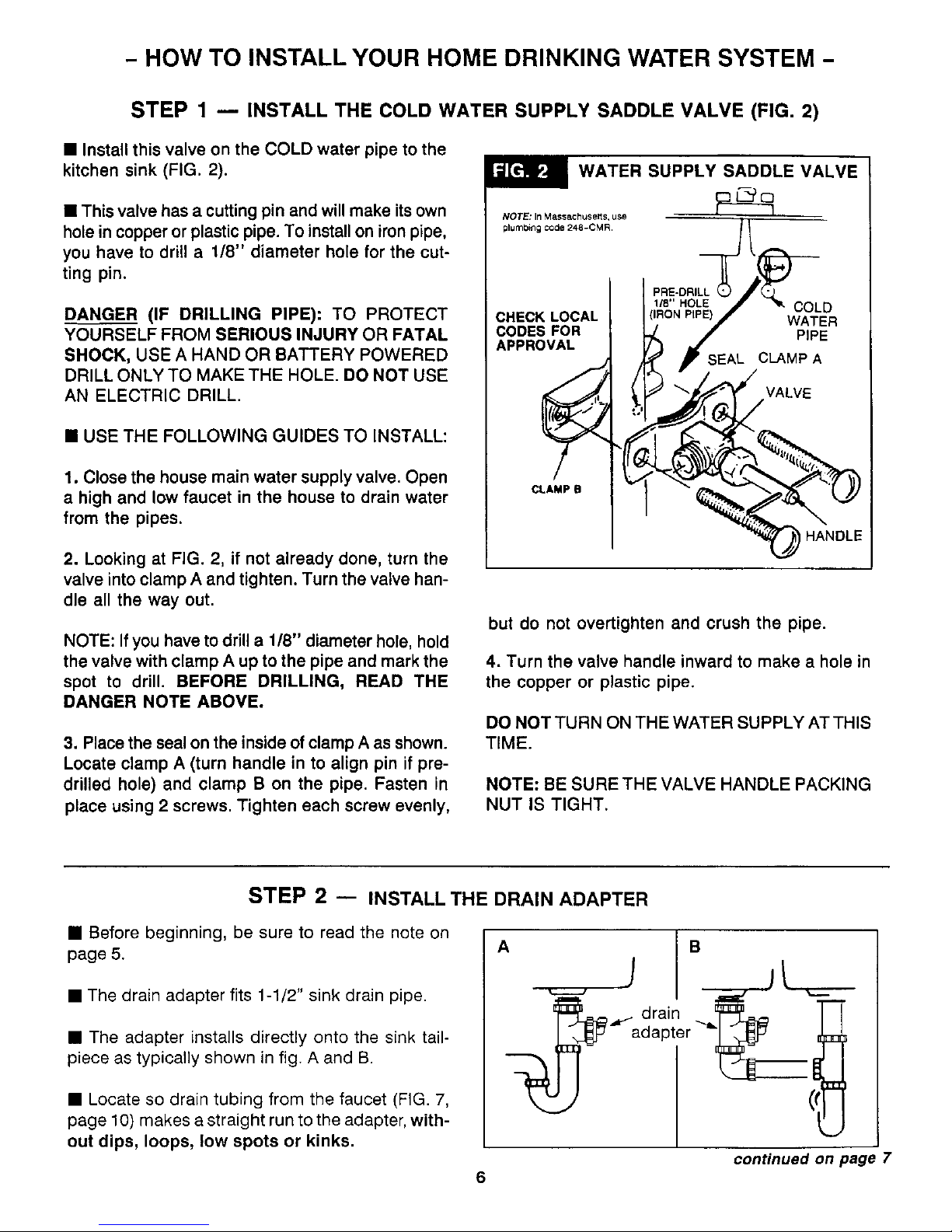
STEP 1 -- INSTALL THE COLD WATER SUPPLY SADDLE VALVE (FIG. 2)
• Install this valve on the COLD water pipe to the
kitchen sink (FIG. 2).
• This valve has a cutting pin and will make its own
hole in copper or plastic pipe. To install on iron pipe,
you have to drill a 1/8" diameter hole for the cut-
ting pin.
DANGER (IF DRILLING PIPE): TO PROTECT
YOURSELF FROM SERIOUS INJURY OR FATAL
SHOCK, USE A HAND OR BATTERY POWERED
DRILL ONLY TO MAKE THE HOLE. DO NOT USE
AN ELECTRIC DRILL.
• USE THE FOLLOWING GUIDES TO INSTALL:
1. Close the house main water supply valve. Open
a high and low faucet in the house to drain water
from the pipes.
2. Looking at FIG. 2, if not already done, turn the
valve into clamp A and tighten. Turn the valve han-
dle all the way out.
NOTE: If you have to drill a 1/8" diameter hole, hold
the valve with clamp A up to the pipe and mark the
spot to drill. BEFORE DRILLING, READ THE
DANGER NOTE ABOVE.
3. Place the seal on the inside of clamp A as shown.
Locate clamp A (turn handle in to align pin if pre-
drilled hole) and clamp B on the pipe. Fasten in
place using 2 screws. Tighten each screw evenly,
WATER SUPPLY SADDLE VALVE
NOTE: In Massachusetts, use
plumb4ng code 248-0MR.
COLD
CHECK LOCAL WATER
CODES FOR PIPE
APPROVAL
CLAMP A
VALVE
CLAMP B
HANDLE
but do not overtighten and crush the pipe.
4. Turn the valve handle inward to make a hole in
the copper or plastic pipe.
DO NOT TURN ON THE WATER SUPPLY AT THIS
TIME.
NOTE: BE SURE THE VALVE HANDLE PACKING
NUT IS TIGHT.
STEP 2 -- INSTALL THE DRAIN ADAPTER
• Before beginning, be sure to read the note on
page 5.
• The drain adapter fits 1-1/2" sink drain pipe.
• The adapter installs directly onto the s(nk tail-
piece as typically shown in fig. A and B.
• Locate so drain tubing from the faucet (FIG. 7,
page 10) makes a straight run to the adapter, with-
out dips, loops, low spots or kinks.
A B
drain
continued on page 7
6
Page 7

- HOW TO INSTALL YOUR HOME DRINKING WATER SYSTEM -
INSTALL THE DRAIN ADAPTER
• Use FIG. 3 and the following guides.
Note: Consult a plumber if you are not familiar with
plumbing procedures•
1. Use a ferrule and nut to assemble the drain
tubing connector to the drain adapter. Turn the
connector to about 45 ° from the 12:00 position,
as shown (to 10:00 or 2:00 position). Tighten the
nut securely.
2. Carefully disassemble the sink drain pipe and
clean the tailpiece to assure a leak-tight fit•
3. Install the drain adapter onto the sink tailpiece,
using a ferrule and nut. Snug the nut, but do not
tighten.
Note: If needed, to make fit, you can cut to shorten
the unthreaded end of the adapter. Do not cut too
short so the adapter will make a leak-tight seal
with the connecting fitting.
4. Assemble the p-trap to the drain adapter, and
other drain pipe fittings as required (check
codes) to complete the drain run.
5. Tighten all connections.
ferrule O
drain adapter
ferrule
cut, if2 t _
needed drain tubing
connector
nut
I
_ o
45 //
STEP 3 u PREPARE MOUNTING HOLE, ASSEMBLE FAUCET AND INSTALL
A. PREPARE MOUNTING HOLE.
1. Pick 1 of the following places for the faucet where
it will fit flat against the surface. Be sure you have
room underneath for the tubing connections (FIG.
7, page 10).
•..in a hole already in the sink (enlarge to 1-1/4"
diameter if needed) to use for an extra faucet
or spray.
...drill a hole (1-1/4" diameter) in the sink top.
BEYOND REPAIR, CONSULT A QUALIFIED
PLUMBER OR INSTALLER FOR GUIDES
BEFORE DRILLING HOLES IN PORCELAIN OR
STAINLESS STEEL.
•.. drill a hole (1-1/4" diameter) in the countertop
next to the sink.
2. Drill the mounting hole.
3. Place plumbers putty around the edge of the hole
to prevent water leakage around the faucet base.
CAUTION: TO AVOID DAMAGING A SINK
7
Page 8

- HOW TO INSTALL YOUR HOME DRINKING WATER SYSTEM -
ASSEMBLE FAUCET AND INSTALL - continued
B. ASSEMBLE FAUCET (FIG. 4)
1. Remove the hex nut, and all other parts shown
in the dotted line box, FIG. 4.
2. Insert the faucet stud through the top gasket and
faucet base. Then, replace the hex nut and tighten.
DO NOT OVERTIGHTEN AND BREAK THE
FAUCET BASE.
NOTE: The faucet may include some small parts
that are not used.
3. Wet the o-rings (2) on the faucet spout. Push the
spout into the faucet body until it bottoms in the
cavity.
C. FASTEN FAUCET IN PLACE
1. Looking at FIG. 5A, locate the faucet support and
gasket over the sink or countertop mounting hole.
NOTE: First, breakout small button and save for use
in step 10.
2. Turn the special nuts (FIG. 5B) a few turns onto
the 1-3/8" long screws.
3. Place a screw into a notch in the faucet support,
with the nut on the underside of the mounting hole
(FIG. 5C). Use a finger to hold the nut and tighten
the screw until snug. In the same manner, install
the second screw and nut. BE SURE THE SUP-
PORT IS POSITIONED CORRECTLY, THEN
TIGHTEN BOTH SCREWS EVENLY UNTIL THE
SUPPORT IS HELD FIRMLY IN PLACE.
4. As shown in FIG. 6, insert the washer into the
tubing adaptor. Turn the adaptor onto the faucet
stud, and tighten.
5. Move the RO assembly into installation position
under the sink, or other desired location. Route the
2 lengths of tubing, marked "FAUCET", and "1/4"
BARB ON FAUCET", from the bottom, upward
through the mounting hole and faucet support (FIG.
6).
6. Using the brass tubing nut, fasten the 3/8"tub-
ing (marked "FAUCET") to the tubing adaptor and
faucet
body
A
gasket
/
plumbers
putty
8
FAUCET AND BASE
ASSEMBLED
faucet
suppod
button
(use in step 10)
screw(2)
nut (2)_,._
mounting
hole
C
TOP VIEW screw (2)
N_1/ mounting
_ hole
_) " nut (underside
"of mounting hole)
faucet support
Page 9

- HOW TO INSTALL YOUR HOME DRINKING WATER SYSTEM -
tighten the nut. NOTE: Cut tubing as needed for
neat appearance, but keep long enough to alllow
easy service of the RO system.
7. If needed, cut the 1/4" tubing (marked "1/4"
BARB ON FAUCET") to length. Then, push the end
all the way onto the 1/4" barb fiting on the faucet.
8. Take the 27" long separate piece of 3/8" tubing
and pass 1 end down through the faucet support.
Push the other end all the way onto the 3/8"barb
fitting on the faucet.
9. Feed the faucet base leadwire down through the
faucet support.
10. Lower the faucet and base down onto the faucet
support, carefully working the tubing and leadwire
through the support. Use the 5/8" long screw to
fasten base and support together. Insert the but-
ton, removed from the support in step 1, into the
hole to cover the screw.
faucet base -_
1/4" barb
fitting
3/8" barb
fitting
washer
tubing
3/8"
faucet su
NOTE:FOREASE
OFSERVIC_AND
MAINTENANCE,KEEP
TUBINGLENGTHSLONG
ENOUGHSOREMOVALOF
THEROSYSTEMFROM
UNDERTNt5SINHIS
POSSIBLE.
1/4" tubing
(1/4" BARB
318" tubing,
27" long
button
faucet base
leadwire
STEP 4 -- MAKE ELECTRICAL, AND REMAINING TUBING CONNECTIONS
A. INSTALL BATTERY PACK iN ELECTRONIC
BOX.
nectors together. Place the battery pack inside the
electronic box and install the back cover.
1. Looking at FiG. 7, page 10, remove the rubber
retainer holding the electronic box and postfilter in
the holder.
2. Pull the electronic box from the holder and
remove the back cover.
4. Reinsert the electronic box and postfilter into the
holder bracket.
5. Replace the rubber retainer around the holder.
3. Fasten the battery pack (BE SURE BATTERIES
ARE INSTALLED CORRECTLY, AS SHOWN ON
THE BATTERY HOLDER) and electronic box con-
continued on next page
9
Page 10

- HOW TO INSTALL YOUR HOME DRINKING WATER SYSTEM -
MAKE REMAINING RO CONNECTIONS - continued
B. CONNECT TUBING, FAUCET TO DRAIN TUB-
ING CONNECTOR
Looking at FIG. 7 and page 16, run the 3/8" x 27"
tubing from the RO faucet, to the connector at the
adapter you installed in the sink drain pipe. Cut this
tubing as needed to route in as straight of a run as
possible without dips, loops, low spots or kinks.
Be sure the end of the tubing is cut square, then
push the end into the connector until itstops (about
11/16"). Pull on the tubing to be sure it is held se-
curely.
C. CONNECT TUBING TO WATER SUPPLY
Use the tubing insert, ferrule and nut, at the water
supply saddle valve, to fasten the remaining 1/4"
tubing (marked "WATER SUPPLY"). Tighten the
nut with a wrench.
D. Fasten the faucet base and electronic box lead-
wire connectors together, routing where dry, and
out of the way.
STEP 5 -- SANITIZING, PRESSURE TESTING, PLACING IN "SERVICE"
A. DO THE SANITIZING PROCEDURES, PAGE
15. THEN, CONTINUE WITH STEP B.
B, Double check all tubing connections to be sure
they are tightened.
C. Open the house main water supply valve and
the supply saddle valve (turn handle fully out). Open
the tank shutoff valve...see below.
D. In about 4 hours, pressure will start to build in
continued on next Daae
FAUCET
3/8" tubing,
27" long (cut to
length needed)
,-faucet base
DRAIN ADAPTER--._
2
HOT WATER
SUPPLY SADDLE VALVE
COLD WATER
1/4" tubing
(WATER SUPPLY)
i
(1/4" see steps 6 & 7,
pages 8 & 9, and
3/8" tubir FIG. 6 to
connect
OPEN
TANK
SHUTOFF VALVE
posffilter
CLOSED
ferrule
nut
NOTE: Codes in tile state of Massaei_usetbs raqutre mstah
/at,on Oy a licensed plumt_er, and do not permit the use of
the saddle valve¸ For insla_lation, use plumbing code
248-CMR of the CommonweaJth of Massachusetts¸
box
RO
ASSEMBLY
leadwire connection
batte_
pack
10
Page 11

- HOW TO INSTALL YOUR HOME DRINKING WATER SYSTEM -
the RO system. At that time, carefully check all fit-
tings and tubing connections for any water leaks.
Correct leaks if any are found.
E. IMPORTANT PURGING INSTRUCTIONS:
The RO cartridge contains a food grade preser-
vative that you should clean from it before using
the system. The preservativewillgive product water
an unpleasant taste and odor.
1. After the storage bladder has filled (takes about
4 hours), open the system faucet until the bladder
is empty.
2. Allow the bladder to fill again for about 4 hours,
then open the faucet and empty. After 4 purgings,
the system is ready to make product water for your
use,
- HOW YOUR HOME DRINKING WATER SYSTEM WORKS -
Water from the cold supply pipe saddle valve is
directed through 1/4" tubing, to the electronic box.
Here, the total dissolved solids (TDS) content, of
the supply water, is measured. Water flow continues
to the RO prefilter.
automati
shutoff
PREFILTER - The prefilter is a replaceable tank
sediment-activated carbon cartridge. It removes shutoff
sand, silt, dirt, other sediments, and up to 2 parts RO water
per million (ppm) chlorine from the supply water, to
CHLORINE WILL DESTROY THE RO MEM- postfilter
and
BRANE... SEE PAGES 4 AND 13. Filtered, clean, faucet
chlorine-free water flows from the prefilter and to
the RO membrane.
RO MEMBRANE CARTRIDGE - The RO car-
tridge, located inside of the prefilter, is a tightly-
wound, semi-permeable membrane. Semi-
permeable means water will work through the mem-
brane, but first, dissolved solids and organic mat-
ter are screened out and flushed to the drain. The
screened, high quality product water goes to the
storage area, or to the postfilter if the RO faucet
is open.
POSTFILTER - After leaving the storage area, but
before going to the faucet, product water goes
through the postfilter. The postfilter is also a
sediment-carbon type filter. It removes any remain-
ing tastes, odors or sediments from the product
continued on next page
supplywater
IN
prefilter
cartridge
RO
membrane
cartridge
RO
housing
check
valve
bladder
11
Page 12

- HOW YOUR HOME DRINKING WATER SYSTEM WORKS -
POSTFILTER - continued
water. High quality drinking water flows from the
postfilter and to the faucet.
NOTE: Before going to the faucet, product water
passes through the electronic box and remaining
TDS is measured by a sensor.
FAUCET - The sinktop or countertop faucet
dispenses the drinking water. It has a hand
operated, spring loaded lever to keep the faucet
closed and to prevent waste. You can keep the
faucet open by pushing upward on the lever and
locking it against the spout. To meet plumbing
codes, an air-gap is built into the faucet drain water
tubes. The air-gap prevents a back siphon of drain
water.
MONITOR - When the faucet is opened, lights on
the faucet base show how the RO system is
working.
• FLASHING GREEN - The RO system is giving you
high quality product water.
NOTE: The green light may stop flashing when the
supply of RO water is nearly gone, and flow from
the faucet decreases. This is a normal condition.
• FLASHING AMBER "FILT" - The prefilter car-
tridge and postfilter need replacing. Also replace
the control box batteries...see page 14. This
light comes on after 6 months, or after 900 gallons
of product water use.
FLASHING AMBER "RO" - The RO membrane
cartridge needs replacing. (BE SURE TO
REPLACE BA-I-FERIES...SEE ABOVE, TO
ASSURE PROPER "RO" LIGHT OPERATION.)
The RO light comes on when the RO membrane
no longer removes at least 75% of the TDS from
the water supply.
NOTE: Disregard the "RO" light when it flashes
for a few seconds at a time.
AUTOMATIC SHUTOFF - When the storage
area has filled with product water, and the RO
faucet is closed, the automatic shutoff is forced clos-
ed. Water flow through the system is stopped before
it can enter the RO module, preventing continued
flow to the drain. The shutoff remains closed, and
water is saved, until the faucet is opened again.
CHECK VALVE - A check valve (FIG. 8) is built
into the product water outlet of the RO housing. The
check valve prevents a backward flow of product
water, from the storage area, to the membrane. A
backward flow could rupture the RO membrane.
FLOW CONTROL - The flow control (FIG. 9)
keeps flow through the RO cartridge at the need-
ed rate for high quality product water. A cone
shaped screen fits over the flow control to help pre-
vent plugging with drain water sediments.
- CARE OF YOUR HOME DRINKING WATER SYSTEM -
To keep your Home Drinking Water System work-
ing and making high quality water, you must make
sure supply water is always within the limits shown
on page 17. This gives you the longest life from the
PREFILTER CARTRIDGE, RO MEMBRANE CAR-
TRIDGE, and POSTFILTER. Each of these will wear
out in time and need replacing.
CAUTION: BEFORE WORKING ON THE
SYSTEM, DO THE FOLLOWING TO
RELIEVE WATER PRESSURE IN THE RO
TANK.
la. Turn off the water supply to the RO (turn the
supply saddle valve all the way inward...FIG. 7).
b. Open the product water faucet and keep open
until water flow stops.
the water, disconnect the posffilter and empty
the storage bladder.
,
Looking at FIG. 9, or page 18, remove the pro-
tective cap and depress the relief valve stem,
allowing air to ENTER the tank (do not block
valve passage). Release the valve stem
AFTER flow from the shutoff valve slows to a
slight drip. Replace the protective cap.
CAUTION: This valve is for vacuum relief only. DO
NOT attempt to pressurize the tank.
3. Reconnect the postfilter.
c. Using a 2 gallon (minimum) container to catch
12
Page 13

- CARE OF YOUR HOME DRINKING WATER SYSTEM -
PREFILTER CARTRIDGE - You must replace
the prefilter cartridge often to protect the RO mem-
brane from being destroyed bychlorine, and/or from
plugging with sediments from the water supply. If
you have chlorine in the water, replace the cartridge
at least every 6 months. If the prefilter cartridge
plugswith sediments, waterflow intothe RO system
drops, slowing the making of qualityRO water. The
RO membrane may also begin to plug with
sediments. If this happens, you maynot get enough
RO water for your needs.
NOTE: The amber "FILT" light on the faucet base
will begin to flash after 6 months or 900 gallons of
product water use to tell you the filter cartridge
needs replacing.
cone screen
RO Cap __
control
_riu:;w_ L_dbg_n e
protective
cap _ o-ring end down
vacuum
relief
prefilter
BOTTOM
END
(2)
--..clamp
section (2)
electronic
box
POSTFILTER - Always replace the postfilter at the
same time you replace the prefilter cartridge. The
postfilter gives the product water a final filtering of
any tastes and/or odors that may remain.
TO REPLACE THE POSTFILTER
CAUTION: BE SURE TO RELIEVE PRESSURE,
STEPS 1, 2 AND 3, Bo'n'OM OF PAGE 12.
1. Disconnect tubing at both ends (Fig. 9).
2. Pull the filter from the holder and remove fittings
from both ends.
3. Observing the flow arrow, on new filter, turn the
fittings (use Teflon tape) into both ends. The
elbow fitting installs at the bottom end, or outlet.
4. Replace filter into the holder and reconnect the
tubing at both ends.
TO REPLACE THE PREFILTER CARTRIDGE
CAUTION: BE SURETO RELIEVE PRESSURE,
STEPS 1, 2 AND 3, BOTTOM OF PAGE 12.
IMPORTANT: BE SURE YOUR HANDS ARE
CLEAN BEFORE WORKING ON RO SYSTEM IN-
TERNAL PARTS.
1. Remove the clamp retainers and clamp sections
(Fig. 9).
2. Separate the cap from the RO housing (no need
to disconnect tubing) and set aside.
NOTE: If the cap o-ring seal remained in the
RO housing, replace it on the cap.
3. Lift the RO cartridge and prefilter cartridge from
the housing, then separate and dispose of the
prefilter cartridge.
4. Dump water remaining in the RO housing.
5. Slide the RO cartridge INTO THE TOP END of
the new prefilter cartridge, as shown in FIG. 9,
then place into the RO housing.
NOTE: Be sure the bottom end of the prefilter is
at the bottom, and the up arrow ( -_ ) on the RO
cartridge points upward (o-ring seal end down-
ward).
6. Be sure the cap o-ring has lubrication (silicone
grease). Then, push into position and install
clamp sections and retainers,
7. Replace the electronic box batteries.., see page
14.
13
Page 14

- CARE OF YOUR HOME DRINKING WATER SYSTEM -
RO MEMBRANE CARTRIDGE - The useful life
of the membrane cartridge depends mostly on the
pH (see page 17) of your supply water. The lower
the pH, the longer the membrane will last. For ex-
ample, if the feed water has a pH of about 7.0, the
cartridge may last for over 1 year; but if the pH is
high, cartridge life may be shortened. The high pH
weakens the membrane and makes pin hole leaks.
NOTE: The amber "RO" light on the faucet base
will begin to flash when RO water quality drops so
less than 75% of the TDS are removed from the
supply water.
This reverse osmosis system contains a
replaceable treatment component critical for
effective removal of total dissolved solids. The
water should be tested periodically to verify
that the system is performing satisfactorily.
TO REPLACE THE RO CARTRIDGE
1. Refer to page 13 and follow instructions under
"To Replace the Prefilter Cartridge".
2. Remove and replace the flow control and screen
(see steps on this page).
3. Turn on the water supply and PURGE THE RO
CARTRIDGE... SEE PAGE 11.
BATTERIES IN ELECTRONIC BOX - Always
replace the batteries (4, "AA" alkaline) in the elec-
tronic control box after installing a new prefilter car-
tridge and postfilter. Good batteries assure proper
operation of the indicator lights. Removing the bat-
teries also resets the 6 month or 900 gallon period
for monitoring the filter cartridges. See FIG. 7 on
page 10.
FLOW CONTROL - A clean flow control is a must
for the RO membrane to make high quality product
water. The flow control keeps water flow through
the membrane at the right rate to get the best quality
product water. If the control becomes plugged, so
water can't get through, it will only take a short time
for the RO membrane to become useless. A small,
cone-shaped screen is positioned over the flow con-
trol (FIG. 9) to help keep the flow control clean.
Every time you work on the RO system, check the
flow control and screen to make sure they are clean.
TO REPLACE FLOW CONTROL AND SCREEN
CAUTIONS: To install the screen, place the cone
end into the RO cap. Then carefully push it in us-
ing 1/4" tubing as a tool. Do not force in farther after
you feel resistance. Visually check to be sure it is
properly positioned.
When installing the flow control, tighten the nut by
hand, then another 1/4 to 1/2 turn with a pliers. DO
NOT OVERTIGHTEN AND DISTORT OR CRUSH
THE TUBING AND FLOW CONTROL.
SERVICING THE BLADDER
If the bladder should require inspection and replace-
ment, use the following guides. Refer to the parts
illustration on page 18.
CAUTION: BE SURE TO RELIEVE PRESSURE,
STEPS 1,2 AND 3, Bo'n'OM OF PAGE 12.
1. Remove the vacuum relief valve (use 7/16"
socket).
2. Rotate the tank shutoff valve 90o and pull from
the RO housing.
3. Apply downward pressure on the RO cap while
rotating counterclockwise 90 o.
NOTE: If the cap turns in the RO housing, first do
steps 1 and 2 under "To Replace the Prefilter Car-
tridge", page 13.
4. Lift the RO housing out of the liner assembly and
PLACE WHERE CLEAN AND SANITARY.
5. Remove the bladder.
NOTE: BE SURE THE INNER SURFACE OF THE
REPLACEMENT BLADDER, AND THE OUTER
SURFACE OF THE RO HOUSING ARE CLEAN.
USE DISH SOAP AND HOT WATER TO CLEAN
AND RINSE.
6. Install the bladder into the liner assembly. Wet
the top bead of the bladder with water, or apply
a light coating of silicone grease.
14
Page 15

- CARE OF YOUR HOME DRINKING WATER SYSTEM -
7. Install the RO housing, push downward and
rotate 900 clockwise to lock in place.
8. Replace the tank shutoff valve and rotate 900 to
lock.
9. Using the o-ring seal, replace the vacuum relief
valve.
10. DO THE SANITIZING AND PURGING PRO-
CEDURES, PAGE 10.
AUTOMATIC SHUTOFF SERVICE
If the shutoff assembly, on the RO cap, requires ser-
vice, reassemble parts exactly as shown in FIG. 10.
Be sure to align indicated marks to properly torque
cap to RO cap.
arrow
align
holes
RO cad
phragm
plunger
support
- plunger
Lphragm
mark
p support
o-ring
WHEN INSTALLING CAP,
TIGHTEN BY HAND.
THEN, USE A PLIERS
TO TIGHTEN AND ALIGN
MARK ON CAP WITH
ARROW ON RO CAP
SANITIZING THE RO SYSTEM
Sanitizing is recommended upon installation of the
RO system, and after servicing inner parts of the
RO housing, and cap. IT IS IMPORTANT FOR THE
SERVICE PERSON TO HAVE CLEAN HANDS
WHILE HANDLING INNER PARTS OF THE
SYSTEM.
1. BE SURE WATER SUPPLY TO THE RO IS
TURNED OFF, AND THE RO FAUCET IS OPEN.
2. Remove the clamp retainers and clamp sections,
Fig, 9, page 13.
3. Lift the cap from the RO housing (no need to
disconnect tubing) and move aside.
NOTE: IF THE CAP O-RING SEAL REMAINED IN
THE RO HOUSING, REPLACE IT ON THE CAP.
4. Remove the RO cartridge and prefilter car-
tridge from the RO housing. If needed, flush hous-
ing with fresh, clean water.
5. Fill the RO housing, with fresh water, to about
1 inch from the top. Add 1.0 oz. of chlorine (ordinary
5,25% household bleach... Hilex, Clerox, etc.) and
mix in the water. DO NOT ADD CHLORINE FIRST.
Concentrated, it will attack plastics,
6. Replace the cap, with o-ring, and install the re-
taining clamps.
7. Connect the RO faucet product water tubing
directly to the tank shutoff valve, isolatinq the car-
bon postfilter.
8. Open the tank shutoff valve, and the water supply
to the RO. Open the RO faucet, locking the lever
upward, against the spout.
9. Allow water to circulate through the system un-
til the bleach odor is gone.
10. Turn off the water supply to the RO. Close the
RO faucet after water flow stops.
11. Reconnect the postfilter (replace used filter) to
the RO system, Fig. 9, page 13.
12a. Do steps 2 and 3.
b. Replace the RO cartridge and prefilter car-
tridge (BE SURE YOUR HANDS ARE
CLEAN).
c. Do step 6.
d. Turn to page 10 and do the pressure testing
and purging steps B through E.
15
Page 16

- CARE OF YOUR HOME DRINKING WATER SYSTEM -
RO CARE GUIDE
MODEL RO 2000 WITH MONITOR
IMPORTANT: BEFORE DOING THE FOLLOWING MAINTENANCE, BE SURETO RELIEVE
PRESSURE AND ALLOW AIR TO ENTER THE TANK, STEPS 1, 2 AND 3, PAGE 12.
t. Replace the prefilter cartridge and postfilter when the amber "FILT" light begins to flash
while taking product water from the RO faucet. Clean or replace the flow control and screen.
and replace the batteries in the electronic control box.
2. Replace the RO membrane cartridge when the amber"RO" light begins to flash while tak-
ing product water from the RO faucet. Clean or replace the flow control and screen.
NOTES: a. If slow making of product water occurs before an amber light begins to flash,
replace the prefilter cartridge. If production rate does not improve, then replace the postfil-
ter and RO membrane, b. If product water flow from the RO faucet is slow, do the steps
referred to in the IMPORTANT note above.
OTHER TROUBLESHOOTING
PROBLEM
Chorine taste and/or odor in
the RO product water
Other taste and/or odor
CAUSE
The ppm of chlorine in your water supply
exceeds maximum limits, and has de-
stroyed the RO membrane.
The prefilter is no longer removing chlo-
rine from the water supply.
Postfilter expended.
RO membrane cartridge expended.
! Contamination in product water storage.
Water supplytothe RO system not within
specifications.
RO membrane cartridge expended.
Indicator lights, on faucet
! base, not working
CORRECTION
Ifthewater supplycontains morethan 2.0 ppmof chlorine, addi-
tional filtering of the water supply to the RO is needed. Correcl
this condition before doing maintenance on the RO system.
Replace the RO membrane cartridge, flow control, screen, pre-
filter, postfilter, and batteries in the electronic box.
Replace the postfilter. Iftaste and odor persists, replace the pre-
filter, RO membrane cartridge, flow control, screen, and batter-
ies in the electronic box.
Use sanitizing procedures. Then replace the postfilter.
High total dissolved solids Increasewaterpressure, preconditionthewater, etc.,aeneeded
(TDS) in product water to conform before doing maintenance on the RO system.
Replace the RO membrane cartridge, flow control, screen, pre-
filter, postfilter, and batteries in the electronic box.
Slow product water flow from Vacuumcreated in storageareeforprod- Open the vacuum relief valve and allow the tank to fill with air.
the RO faucet uct water. See page 12.
Waterleaking from faucet air- Drain side of faucet airgap (3/8" tubing) Inspect and eliminate restriction or plug. Refer to installation
gap hole plugged, restricted, or incorrectly con- instructions for proper drain connection,
nected to drain point.
Faucet base leadwire not connected to
electronic box leadwire.
Batterypacknotconnected to electronic
box.
Connect
Batteries installed incorrectly, or ex- Observeorientationmarkingsontheholderandinstallcorrectly.
_ended. Replace batteries ifold.
Leadwires or connectors damaged. Inspect and repair or replace as needed.
Tubing Connection at Drain Adapter: Cut the end of
the tubing square and push into the fitting as far as
possible (11/16"), Pull on the tubing to be sure it is
held firmly in place.
To Disconnect Tubing: Push the tubing inward to de-
press the fitting collet. Hold the collet in while pulling
the tubing out.
tubing
collet
I
I
I
16
Page 17

- DIMENSIONS / SPECIFICATIONS -
•=-- 8_ 1/8,,--.-_
21"
Supply water pressure limits ...................................... 40-125 PSI
Supply water temperature limits ..................................... 40-100OF
Maximum total dissolved solids (TDS) ............................... 2000 PPM
Maximum water hardness @ 6.9 pH .................................. 10 GPG
Maximum iron, manganese, hyd. sulfide .................................... 0
Chlorine in supply water
(SEE PAGE 4) ......................................... Max. 2.0 PPM 1
Supply water pH limits ................... •.......................... 4-10 pH
Product (quality) water, 24 hrs.* ..................................... 11 gals.
Waste water per gal. product water, 24 hrs.* ............................ 3 gals.
Percent rejection of TDS, minimum (new membrane)*. ..................... 90o/0
Storage capacity .................................................... 1 gal.
Product water vending flow ......................................... 1/2 GPM
METRIC
280-860 kPa
5-40oc
41.6 liters
11.4 liters
3.8 liters
1.9 liters/min.
*Supply water at 55 psi and 770F with 750 parts per million sodium chloride. Quality water production, amount
of waste water and percent rejection all vary with changes in pressure, temperature and total dissolved
solids. See the charts below for additional production and rejection rates.
1 Up to 2,0 ppm removedby the RO prefiltercartridge.
NOTE: This productis testedand complieswith Water QualityAssociation Standards.
You canusethe following chartsto determine ROperformance for your specificwaterpressure and total dissolved
solidscontent. Theresultsarefromtestsconducted onthe ROmembraneusing e9"longflow control ata25%product
water recovery rate.
PRODUCT WATER GALLONS PER DAY PERCENT REJECTION OF TDS
(PRODUCT WATER OUTLET OPEN) (PRODUCT WATER OUTLET CLOSED)
120 39.5 36 33 29
110 36.5 33 30 26
100 33.5 30 27 23
FEED 90 30 27 24 20
WATER 80 27 24 21 17
P_,_URE
23.5 21 18 14
TO R0 --
(PSI) 60 20.5 17.5 15 11
50 16.5 14.5 11.5 8.5
40 13 11 8.5 5.5
24 19
21.5 17
19 14.5
16 12
13,5 9.5
10.5 7
/
/PRESSURES/
/ TOO LO_//,_
/i,)THISDs
120 98.3 97.8
110 98.3 97.7
100 98.2 97.6
90 98.2 97.5
80 98.1 97.4
70 98 97.3
60 97.8 97
50 97.5 97
40 96.7 95.5
97.2 96.4
97.1 96.3
97 96.1
96.8 95.8
96.6 95.5
96.4 95
96 94.3
95.2 93
93.9 90.5
94.8 93,5
94.5 92.8
94.2 92.1
93.8 91.2
93.1 90
92.1 87.9
WATER _"
PRESSURES
TOO LOW/
TOTAL DISSOLVED SOLIDS (TDS)
TOTAL DISSOLVED SOLIDS (TDS)
17
Page 18

- REPAIR PARTS -
WaterWorks _
I 1
I
O I
I
HOME DRINKING WATER SYSTEM Undersink Reverse Osmosis MODEL RO 2000
]
I 36 -----_(_
DRAIN I
ADAPTER I 35 ---'-'-"_(_;J[
I"'---,_ 5 34 "'"""_ _
33 .-.----.-_ "_ 37
32 --"--'-_,_
27
i
TO
7 AIRGAR
i • 1/4" BARB
24 _ 26
\
Z 3 "'\ I / 19
..... _ ....... ""-L I 18 ...,..,_
L_ SADDLE VALVE
NOTE: Codes in the state of Massachu-
setts require installation by _ licensed
plumber, and do not permit the use of the
saddle valve, For installation, use pFumbfng
code 248-CMR of the Commonwealth of
Massachusetts.
38
/
18
46
43
44
Page 19

- REPAIR PARTS -
WaterWorks TM HOME DRINKING WATER SYSTEM Undersink Reverse Osmosis MODEL RO 2000
KEY
NO.
1
2
3
4
5
6
7
8
9
10
11
12
13
14
15
16
17
18
19
20
21
22
23
24
25
26
PART
NUMBER
7205465
1260600
7207734
9043201
7192230
9003204
7131331
7124986
7114509
7116763
7131349
9003203
7011272
7087485
42-34709
9004502
7128702
7118414
0900044
7140869
7109910
7121954
7155018
7176292
7088033
42-34706
DESCRIPTION OF PART
Faucet
Washer
Adaptor (Includes key nos. 2 & 4)
Nut, 3/8" Tubing
Drain Adapter
Nut, 1/4" Tubing (6)
Tubing Insert, 1/4" (5)
Elbow, 1/4" NPTx 1/4" Tubing
Tank Shutoff Valve
O-ring Seal, 7/16" x 5/8" O.D.
Tubing Insert, 3/8" (5)
Nut, 3/8" Tubing (5)
Saddle Valve (water supply)
Connector, 1/4" NPT x 3/8" Tubing
(a) Post Carbon Filter][ replacement
(b) Pre Carbon Filter .jr package1of eachhaS
Elbow, 1/4" NPT x 3/8" Tubing
Filter Holder
Liner Assembly
O-ring Seal, 5/16" x 7/16" O.D.
Vacuum Relief Valve
Bladder
Bali-Check Kit
RO Housing
Clamp Section (2)
Clamp Retainer (2)
RO Membrane Cartridge (Includes
key nos. 27 & 28)
KEY
NO.
27
28
29
3O
31
32
33
34
35
36
37
38
39
4O
41
42
43
44
45
46
47
PART
NUMBER
7167764
709503O
7115610
7110466
7113846
7113838
7124677
7116755
7131721
7125932
42-34704
0900156
7214032
0900713
7115262
7115725
7115822
7170880
7090771
7051206
7126506
7157280
7161823
7214105
DESCRIPTION OF PART
Flow Control
Cone Screen
O-ring Seal, 3-1/8" x 3-3/8" O.D.
RO Cap
Support, Plunger
Plunger
Top Support
O-ring Seal, 1-3/16" x 1-3/8" O.D.
Cap
Diaphragm Kit []
RO Electronics Assembly
Screw, #6-32 x 5/8"
Faucet Base (Includes key nos. 39,
41,42, 43, 46 and 47)
Screw, #6-32 x 1-3/8" (2)
Faucet Support []
Nut (2)
Battery Holder []
Electronic Box
Gasket
Gasket
Cable Extender, 15' - optional (ex-
tends connection between faucet
base and electronic box)
Tubing, 3/8" x 20'
Tubing, 1/4" x 20'
Owner's Manual
[] Place the diaphragm with the small hole into the RO cap first.
Locate the small hole over the vent hole in the cap, at the 12:00
position (see page 13).
[] Includes the button that covers screw, key no, 39.
,_ Purchase batteries locally (4 req'd., "AA" alkaline)
19
Page 20

- REMOTE INSTALLATION LOCATION -
INSTALLING RO ASSEMBLY, AND/OR SUPPLY SADDLE VALVE IN REMOTE LOCATION
Longer lengths of tubing are available from Sears
(see page 19) for installingthe RO assembly, and/or
water supply saddle valve away from the RO faucet.
Examples: In the basement, under the kitchen or
bathroom sink. In a closet or room nearby the kit-
chen or bathroom.
You can run the RO assembly drain tubing direct-
ly to an open drain and bypass the faucet. Suitable
open drains include a laundry tub, floor, sump and
stand pipe drains. It is very important to keep the
end of the RO drain tubing at least 1-1/2" above
the drain point. This provides an air gap to prevent
a back-siphon of sewer water.
Omit the following steps:
- all of step 2, pages 6 and 7.
- steps C7 and C8, page 9.
- step 4B, page 10.
RO WATER
FAUCET
COLD WATER
SOURCE
_airgap
STANDPIPE
RO drain
tubing
OPTIONAL DRAIN
TUBING RUNS
SUMP
airgap
FLOOR DRAIN LAUNDRY TUB
When ordering parts, always provide the following information:
• Product Type: WaterWorks TM Undersink Reverse
Osmosis Drinking Water System
• Model: RO 2000
• Part Number: from page 19
• Part Description: from page 19
For the repair or replacement parts you need
Call 7 am - 7 pm, 7 days a week
1 - 800 - 366 - PART
(1 - 800 - 366 - 7278)
 Loading...