

Page 1

SEARS
INSTALLATION
MANUAL
for softeners with
standard flow valve
Caution: Read All
Safety Guides Before
You Start To Install
Your Softener.
If you have questions when
installing, operating or main-
taining your softener, and
when setting the timer, call
this toll-free number...
1-800-426-9345
SAVE THIS MANUAL
Water Softeners
• Safety Guides
• Unpacking
• Where To Install
• How To Install
• Pressure Testing
Use plastic bag and tie provided, to hang manuals nearby
the softener for future reference.
Sears, Roebuck and Co., Hoffman Estates, IL 60179 USA
PRINTED IN U.S.A.
Page 2

INTRODUCTION
I I
This manual gives you the steps needed to install
your new Sears Water Softener. To better under-
stand how the water softener is installed, and to
know what you will need, please read this entire
manual before beginning.
After you have installed the water softener, the
included Owners Manual tells you how to start,
program, operate and maintain it. The owners
manual also has the product warranty, and a
listing of repair parts available from Sears.
Your Sears Water Softener will remove hardness
minerals (measured in grains per gallon...gpg)
and some clear water iron (measured in parts per
million...ppm) from water. See the specifica-
tions, in your owners manual, for the maximum
limits of hardness and iron removal. A water
softener will not improve other water problems
such as acidity, tastes and odors, or iron other
than clear water iron. It will not purify contami-
nated water, or make other unsafe water safe to
drink.
Sears sells a complete line of water treating
equipment to correct various water problems. To
be sure you have the proper type and size
equipment, you must have your water tested.
Your Sears store can give you water test results
for hardness, iron and acidit3_ and tell you what
equipment you need. Simply take at least a 4 oz.
sample of your water to Sears, and they will test
it while you wait. If.you need help to get your
water tested, or if you have other questions
about your water, ask at your Sears store, or call
sears Water Line ...1-800-426-9345.
2
Page 3
TABLE OF CONTENTS
I. i
SECTION 1 BEFORE INSTALLING CHECKS AND TESTS
A. SAFETY GUIDES
B. UNPACKING THE WATER SOFTENER
C. WATER SYSTEM TESTS
PAGE
NO.
4
5
6
SECTION 2
PLAN YOUR INSTALLATION
A. WHERE TO INSTALL THE SOFTENER
B. TOOLS, PIPE AND FITTINGS, OTHER MATERIALS NEEDED
C. TYPICAL SOLDERED COPPER (OR CPVC) IN AND OUT PIPES
D. TYPICAL THREADED IN AND OUT PIPES TO SOFTENER
7
8-9
10
11
SECTION 3
STEP BY STEP GUIDES TO INSTALL
A. ASSEMBLE INLET-OUTLET ADAPTORS, OR PLASTIC BYPASS VALVE 12-13
B. INSTALLING 3-VALVE BYPASS, OR SINGLE BRASS VALVE 14
C. LOCATE AND CONNECT WATER SOFTENER 15
D. CONNECT VALVE AND SALT TANK DRAIN HOSES 16-17
E. PRESSURE TEST--CHECK FOR LEAKS 18
F. GROUNDING_ONNECT TO ELECTRICAL POWER 19-20
RESTART THE WATER HEATER
20
3
Page 4
SECTION 1 BEFORE INSTALLING CHECKS AND TESTS
!
1A. SAFETY GUIDES
• Read all steps, guides and rules carefully be-
fore installing and using your new water softener.
Follow all steps exactly to correctly install. Fail-
ure to follow them could cause personal injury or
property damage. Reading this book will also
help you to get all of the benefits from your water
softener.
• Your water softener will remove hardness min-
erals and "clear water" iron from water, up to the
limits shown on the specifications page of your
owners manual. It will not remove other types of
iron, acids, tastes and odors, etc. It will not purify
polluted water or make it safe to drink.
• Check with your local public works department
for plumbing, electric and sanitation codes. You
must follow their guides as you install your soft-
ener.
• Use only LEAD-FREE SOLDER AND FLUX, as
required by Federal and State codes, when instal-
ling soldered copper plumbing.
• Protect the softener and piping from freezing.
Damage from freezing voids the softener warran-
ty. See how to protect from freezing in your own-
ers manual.
CAUTIONS
PLEASE READ AND COMPLY WITH THE FOL-
LOWING GUIDES TO PREVENT DAMAGE TO
THE SOFTENER OR OTHER PROPERTY,
PERSONAL INJURY, OR POSSIBLE FATAL
SHOCK.
• This softener works on 24 volts only. Be
sure to use the transformer included, and
plug it into a 120V outlet.
• Unplug the transformer right away if the
power cable should become damaged or
frayed. Make repairs before plugging back
into the power outlet.
• Always unplug the softener from electrical
power before removing outer valve covers.
4
Page 5
SECTION 1 BEFORE INSTALLING CHECKS AND TESTS
I
lB. UNPACKING THE WATER SOFTENER
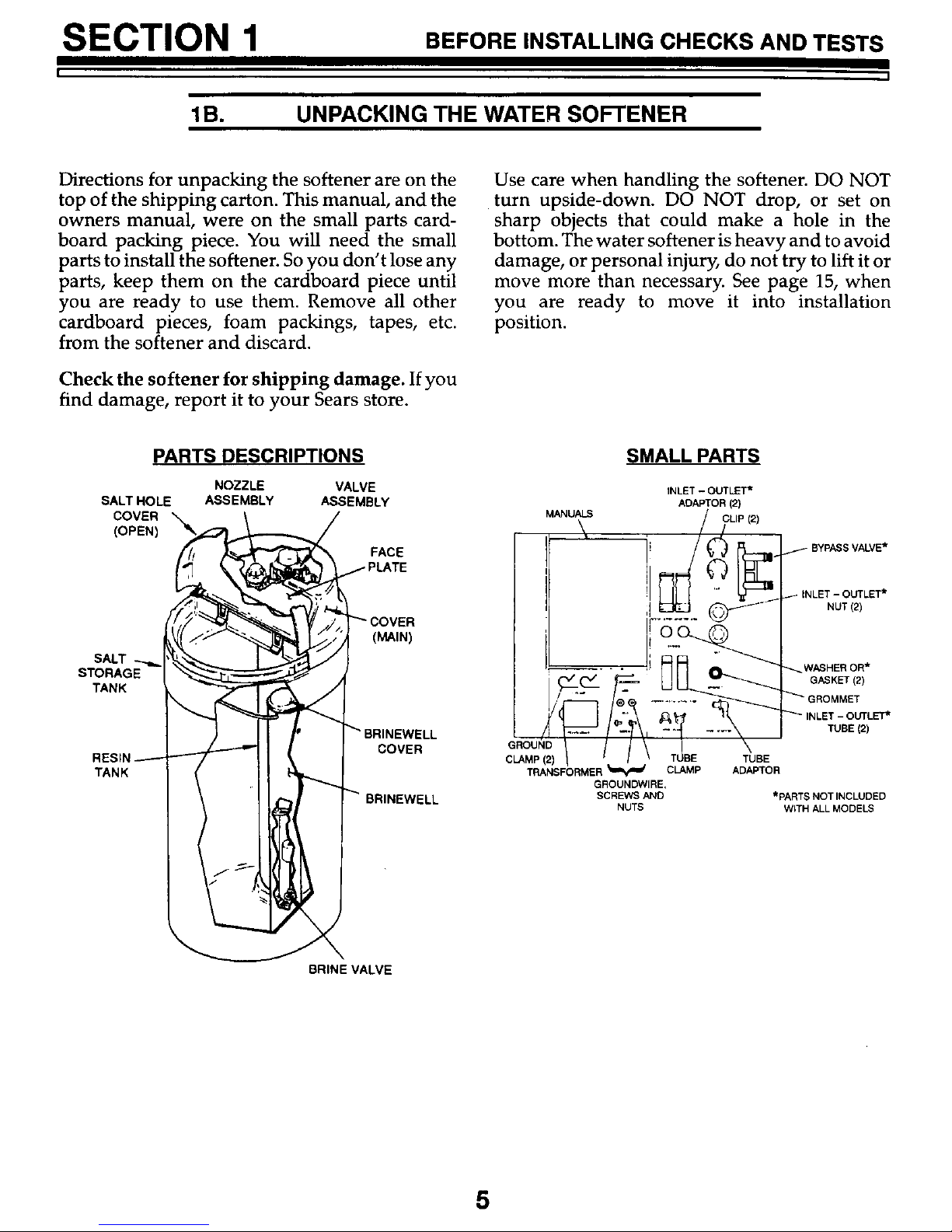
Directions for unpacking the softener are on the
top of the shipping carton. This manual, and the
owners manual, were on the small parts card-
board packing piece. You will need the small
parts to install the softener. So you don't lose any
parts, keep them on the cardboard piece until
you are ready to use them. Remove all other
cardboard pieces, foam packings, tapes, etc.
from the softener and discard•
Check the softener for shipping damage. If you
find damage, report it to your Sears store.
Use care when handling the softener. DO NOT
turn upside-down. DO NOT drop, or set on
sharp objects that could make a hole in the
bottom. The water softener is heavy and to avoid
damage, or personal injury, do not try to lift it or
move more than necessary. See page 15, when
you are ready to move it into installation
position.
PARTS DESCRIPTIONS
SALT HOLE
COVER _
(OPEN)
SALT
STORAGE
TANK
TANK
NOZZLE VALVE
ASSEMBLY ASSEMBLY
FACE
(MAIN)
COVER
BRINEWELL
SMALL PARTS
INLET - OUTLET*
ADAPTOR (2)
MANUALS / CLIP (2)
\ . /
/ o P SV LVE.
;!_" _- I NUT(E)
• . WASHER OR*
GASKET (2)
3ROMMET
i_- OUTLET*
TUBE (2)
GROUND
CLAMP(2)
TRANSFbRMER_ CLAMP
GROUNDWIRE,
SCREWS ANO
NUTS
TUBE
ADAPTOR
*PARTS NOT INCLUDED
WITH ALL MODELS
BRINE VALVE
5
Page 6
SECTION 1 BEFORE INSTALLING CHECKS AND TESTS
lC. WATER SYSTEM TESTS
Has your water supply had a chemical analy-
sis? Please see page 2.
CHECK YOUR WATER PRESSURE -- For your
softener to work right, a water pressure of no
lower than 20 pounds per square inch (psi) is
needed in the house water pipes. The highest
pressure allowed in the water pipes is 120 psi. If
pressure is over 120 psi, buy and install a pressure
reducing valve in the water inlet pipe to the
softelaer.
NOTE:
If water pressure during the day is 100 psi or more,
pressure during the night may go over 120 psi.
Adding a pressure reducing valve may reduce the
flow.
If you have a well water system, look at the
pressure gauge to find the water pressure. Call
your local water department if you have city
water. They will tell you what the water pressure is
where you live.
CHECK YOUR WATER FLOW RATE -- A water
flow of at least 3 gallons per minute is needed. A
lower flow will keep your softener from working
as well as it should. To make an easy check of your
flow rate, do the following. You will need a 1
gallon container (can, jar, pail, etc.).
1. Fully open 2 cold water faucets close to the
point water enters the house.
2. With both faucets open, fill the gallon
container at I faucet while looking at a watch
or clock to see how many seconds it takes.
o
Empty the container and go to the second
faucet (be sure BOTH faucets are still on). Fill
the gallon container at the second faucet and
see how many seconds it takes.
4. Turn off both faucets. Now add the number of
seconds it took to fill the container at both
faucets.
5. Atotal of 90 seconds, or less, means the system
flow rate is good.
FOR FUTURE REFERENCE, ENTER RESULTS OF YOUR WATER SYSTEM TESTS IN THE
"FACTS AND FIGURES TO KEEP" TABLE IN YOUR OWNERS MANUAL.
6
Page 7

SECTION 2 PLAN YOUR INSTALLATION
I I
2A. WHERE TO INSTALL THE SOFTENER
Think of the following points as you choose a
place to put your softener. (see FIG. 1).
* Place as close as possible to the pressure tank
(well water) or water meter (city water).
• Place as close as possible to a water drain such
as a floor drain, laundry tub, sump or
standpipe.
&* Connect to the house main water pipe
BEFORE THE WATER HEATER. Temperature
of water going through the softener must not
be more than 120°F (49°C).
• Keep outside faucets on hard water to save soft
water and salt.
&e DO NOT install in a place where the softener
could freeze. Freeze damage voids the warran-
ty by Sears, Roebuck and Co.
A• Put the softener in a place water damage is
least likely to occur if it develops a leak. Sears
Ake
AO
Ako
or the manufacturer will not repair or pay for
water damage.
A 120V electrical oudet, to plug the transform-
er into is needed within 10 feet of the softener
(the softener has a 10 foot power cable). Be
sure the outlet and transformer are in an
inside place, to protect from wet weather.
So the softener always has electrical power,
use a continuously "live" outlet, that cannot be
accidentally switched off.
When installing in an outside location, you
must take the steps necessary to assure the
softener, installation plumbing, and wiring, are
as well protected from the elements, contami-
nation, vandalism, etc., as when installed
indoors.
Keep the softener out of direct sunlight. The
sun's heat can melt plastic parts.
THE PROPER ORDER TO INSTALL WATER TREATING EQUIPMENT
(Shows sequence of equipment only -- selden, if ever, would all items be needed)
kitchen_ batb_m
COLDf_cet
Sediment or _
Tqste & Odor "'"--_._=_
Cartridge II
Filter LJ
cold-softwater_
*Always put the Iron Filter before the
softener, the Taste & Odor Filter after the
softener, the Neutralizer before an Iron
Filter, etc., as shown.
hardwaterto _ I,r--- citywatersepply
°utsidefaucets71 !
[] E!' 31_ I J ILwe,water*Wly
I I I I | (_ _ pressure or
Phosphate ====_ _ ===_ _ _ I I I {_ "1 captive air
Feeder I II I I L..L_]
I I I Sediment I,,i,llm_\ I I | "_
I ] [Cartridge Filter _.,^..%_.^ I _ I
: -- .---J, _ (optional _ olena_ng I #h '
Taste& Water Auto. Neutral- Auto. location) tank aJ1_I Well
Odor Softener Iron izer Clarifier _ water
Filter Filter Solution
Dispensing System
7
Page 8

SECTION 2 PLAN YOUR INSTALLATION
2B. TOOLS, PIPE AND FWTINGS, OTHER MATERIALS NEEDED
You must first decide how to run in and out pipes
to the softener. Look at your house main water
pipe at the point you will connect the softener. Is
the pipe soldered copper, glued plastic, or
threaded galvanized or brass? What is the pipe
size? What kind of pipe and fittings is it easiest
for you to work with, and what tools do you
have?
Now look at the common plans for in and out
piping on pages 10 (soldered copper) and 11
(threaded). Select the drawing best for you and
use it as a guide to plan what materials you will
need. As you plan your in and out piping, keep
in mind the following check list. Then get all the
materials you will need before you start.
NOTE:
Use page 9 to make a plan drawing for your
specific installation.
Some models may include a plastic bypass
valve, an installation kit and a length of drain
tubing.
,f In and out pipes to the softener must be at
least 3/4 in. size. Some local codes may tell
you to use no less than I in. pipe size (see Note
on pages 10 or 11). You should maintain the
same, or larger, pipe size as the water supply
pipe, up to the softener inlet and outlet.
_t Use copper, brass, or galvanized pipe and fit-
tings. Some codes may also allow CPVC plas-
tic pipe.
Copper and galvanized pipe corrode fast
when connected together. Use pipe and fit-
tings of the same material.
_f You can buy adaptors to go from a copper or
threaded main water pipe to CPVC in and out
pipe.
4
,f
Sears has kits and bypass valves you can buy
to help make installing your softener easier.
See pages 10 and 11.
ALWAYS install a bypass valve or valves. Ei-
ther use 3 shut-off valves, or I of Sears special
valves. Bypass valves let you turn off water to
the softener, but still have water in the house
pipes.
Drain tubing (3/8 in. inside diameter) is
needed for valve and salt tank drains. See
steps I and 2 on pages 16 and 17. Some mod-
els include a length of drain tubing, or you
can buy it at most Sears stores.
Ifa rigid valve drain is needed to comply with
plumbing codes, you can buy the parts need-
ed (see page 16) to change the softener to a 1/2
in. copper tubing drain.
TOOLS NEEDED:---Common and cross
point (Phillips) screw drivers, slip joint pliers
and a tape measure or rule. ALSO...
...for SOLDERED COPPER -- tubing cutter,
propane torch, solid-core LEAD-FREE solder,
paste flux, emery cloth, sandpaper or steel
wool.
...for THREADED PIPE -- hacksaw or pipe
cutter, pipe wrenches, pipe threading tool
pipe joint compound approved for use on po-
table water.
...for CPVC PLASTIC -- hacksaw, adjustable
wrench, solvent cement approved for use on
potable water, primer.
8
Page 9

SECTION 2 PLAN YOUR INSTALLATION
I I
2B. PIPE AND FITTINGS, PLAN DRAWING
YOUR HOUSE MAIN WATER PIPE*
RIGHT
*IN WHAT DIRECTION DOES
THE WATERFLOW? BE SURE
TO PLAN IN AND OUT PIPING
SO WATERFLOW IS TO THE
SOFTENER INLET. PLAN A
CROSSOVER IF FLOW IS
FROM LEFT TO RIGHT.
120V-60Hz
ELEC. I1,',11
OUTLET
DRAW THE PLANS FOR YOUR IN AND
OUT PIPING HERE. BESURE TO FOLLOW
GUIDES LISTED ,PAGE 8. INCLUDE ALL
PIPE, FrI-FINGS AND ACCESSORIES
YOU WILL USE. MAKE A LIST OF ALL
MATERIALS YOU NEED AND BUY THEM
BEFORE YOU BEGIN TO INSTALL THE
SOFTENER.
VALVE
SIDE
VALVE
INLET
SIDE
CROSS-OVER
er Pipe
Outlet_
Inlet
SOFTENER
9
Page 10

SECTION 2 PLAN YOUR INSTALLATION
! !
2C. TYPICAL SOLDERED COPPER (OR CPVC) IN AND OUT PIPES TO SOFTENER
(_ IN AND OUT PLUMBING USING
A 3 VALVE BYPASS
Shut-off
Valves
FITTINGSREQUIREDNOT
IDENTIFIED
90"Elbow(4)
Tee (2)
Pipe(as reg.)
1" NPT X
I
_" Sweat OU'r
Reducer(2) iN
Outlet
SOFTENERf ._ Adaptor-l" NPT
IN AND OUT PLUMBING
(_ USING SEARS SPECIAL PLASTIC
BYPASS VALVE
'F_aw W er pip e
ater In)
*NOTE:
For 1 In. p|umblng connection, buy 2 sweat
adaptors (1 in.female thread x 1 in. sweat) and
plumb direcUytotheinlet -outlet adaptors or by-
passvalve.Threads ontheinlet -outlet adaptors
and bypass valve are 1 in. pipe thread. Do not
usatheinstallation kit,SearsStock No.42-3441,
or the flexible connectors, Sears Stock No.
42-34401.
CAUTION:
DO ALL SOLDERING BEFORE CONNECT-
ING SWEAT ADAPTOR TO INLET-OUTLET
ADAPTORS OR BYPASS VALVE.
OUT
• 1"NPTX
3/4"Sweat
!
Reducer(2)
Outsr_e
Fa[iCef
FITTINGS
REQUIREDNOT
DENTF ED
90' Elbow(2)
Pipe(asreg.)
IN
OuIlet
.I"NPT
VALVE
Outlet
.. Adaptor
SOFTENE
IN AND OUT PLUMBING
') USING SEARS SPECIAL BRASS
BYPASS VALVE
OUT
(Raw
In)
FITTINGS I
REQUIRED NOT
DENT F ED
90" Elbow (2)
Pipe (as reg.)
VALVE
OUT
IN
KIT
Adaptor.l" NPT
J
SEARS KITS AND VALVES TO MAKE
INSTALLING YOUR SOFTENER EASIER
[] YPASS VALVE (Plastic) r-_ BYPASS VALVE (Brass)
Sears Stock No. 42-3437 _ Sears Stock No. 42-3436
(included with some models)
One, easy working valve takes the place of 3 separate valves.
[] INSTALLATION KIT USE AS SHOWN I_,
Sears Stock No. 42-3441 OR TO REPLACE THE
(included with some models) 1" X 3/4" SWEAT
ADAPTORS IN (_)ANB(_.
FLEXIBLE CONNECTORS
Sears Stock No. 42-34401
Allows easy hook up even
ifpipes are note exactly
aligned.
(CHECK LOCAL PLUMBING CODES)
CONNECT FROM IN-OUT
PIPES, AT DOTTED LINE,
DIRECTLY TO THE INLET
AND OUTLET ADAPTORS
OR TO BYPASS VALVE FT].
SEE (_, (_ ,(:_) ANDS.
10
Page 11

SECTION 2 PLAN YOUR INSTALLATION
I I
2D. TYPICAL THREADED IN AND OUT PIPES TO SOFTENER
IN AND OUT PLUMBING USING SEARS
PLASTIC BYPASS VALVE
_rr_i e
FITTINGS
_REQUIREDNOT
9o.Elbow(2)
Union(2)
pipe (as reg.)
OUT
...Outlet 1 I _ 1"x 3/4" reducer*
NOTE:
If you are planning a threaded plumbing installa-
tion, with a 3-valve bypass, use Fig. 2_as a guide.
Use union fittings, as needed, to connect the
plumbing.
For 1 In. plumbing connec-
tion, use a 1 in. threaded
straightconnector.
11
Page 12

SECTION 3 STEP BY STEP GUIDES TO INSTALL
3A. ASSEMBLE INLET-OUTLET ADAPTORS, OR PLASTIC BYPASS VALVE
1. Close the shut-off valve on the house main
water pipe, near the water meter or pressure
tank, to turn off the water.
2. Shut off the gas or electric supply to the water
heater.
3. Open the highest and lowest water faucets in
your house to let water drain from the pipes.
Close faucets after water has drained.
4. If not already done, remove all cardboard or
plastic packing pieces from inside the softener.
Set the cardboard liner (with parts for installing
fastened to i0 where you can easily see it, and
get to parts as you need them.
Remove the salt hole
cover...lift straight up
ward, and the main
cover...pull outward
on 2 tabs to release.
Set both covers aside
so they will not get
scratched or broken.
Salt Hole
Cover
Cover
(Main
5. REMOVE THE INLET AND OUTLET ADAP-
TOllS OR SEARS BYPASS VALVE. STOCK
NO. 42-3437 (FIG. 4, 5 AND 6).
NOTE:
If you will install the bypass valve (use following
steps a and c), the adaptors are not used. If you do
not install the bypass valve, you must use the
adaptors (use following steps a and b).
a° Visually check and remove any foreign materi-
als from the valve inlet and outlet ports (FIG.
4).
Shutoff _ Shutoff ,_-_ Pressure
Meter Pump
Electrical
Panel
bo
Co
INLET AND OUTLET ADAPTORS (Adaptors
and clips are on the cardboard liner). Push the
adaptors into the valve inlet and outlet ports as
far as they will go. Both adaptors are the same
and fit either valve port. Snap the 2 large
holding clips into place, from the top
down as shown._L_ON...BE SURE THE
CLIPS SNAP FIRMLY INTO PLACE SO THE
ADAPTORS WILL NOT PULL OUT...GO TO
PAGE 14.
BYPASS VALVE STOCK NO. 42-3437
-- If not already done, put a light coating of
silicone grease or Vaseline on the bypass valve
o-rings.
Push the bypass valve into the softener valve
as far as it will go. Snap the 2 large holding
clips into place, from the top down as
shown. _UTION...BE SURE THE CLIPS
SNAP FIRMLY INTO PLACE SO THE BYPASS
VALVE WILL NOT PULL OUT...GO TO PAGE
15.
12
Page 13

SECTION 3 STEP BY STEP GUIDES TO INSTALL
I I
3A. ASSEMBLE INLET-OUTLET ADAPTORS, OR PLASTIC BYPASS VALVE
INSTALLING HOLDING CLIP
SIDE VIEW END VIEW
O-ring seal f_--CLIP
Valve Ou_et(See below)
Valve inlet
/
or
f
3YPASS VALVE
Stock NO. 42-3,,437
Pnstallation Adaptor
Valve Body or
Inlet or Outlet Bypass Valve
(Push all the way in)
BYPASS VALVE TURNED
DOWNWARD
NOTE:
The softener includes either the adaptors, or the
bypass valve, depending on the model.
ELECTRONIC DEMAND MODELS ONLY
Be sure the turbine and support are firmly in
placein the valve outlet.
Turbine
'-L_ VALVE OUTLET
IP"_IIb _ (,e_vep_w=
u_/.,_ I I I shipplng plugand
_7_7_ wire)
TurbineSupport
IN
TURN BYPASS VALVE
UPSIDE DOWN TO
CONNECT TO FLOOR
LEVEL PLUMBING
13
Page 14

SECTION 3 STEP BY STEP GUIDES TO INSTALL
I I
3B. INSTALL 3-VALVE BYPASS, OR SINGLE BRASS BYPASS VALVE
1. INSTALLING 3 VALVE BYPASS, OR SEARS
BYPASS VALVE, STOCK NO. 42-3436, AND
PIPES (FIG. 7)
a. Cut the house main water pipe where you will
connect the softener. Loosely put together
pipe, fittings, and the 3 valves or Sears special
bypass valve. Place valve(s) within easy reach.
IMPORTANT:
When looking at the front of the softener, the
inlet is on the right side. If water in your house
main water pipe runs from left to right, be sure to
use a "cross-over" as shown on page 9.
b. When all pipe, fittings and valves make a good
fit together, tighten all threaded joints (use
pipe dope on outside threads), or solder.
BYPASS VALVES
SINGLE VALVE BYPASS 3-VALVE BYPASS
Inlet _'TO
Softener
fnlet
14
Page 15

SECTION 3 STEPBYSTEPQUIOESTOINSTALL
I I
3C. LOCATE SOFTENER AND CONNECT PIPES
1. MOVE THE SOFTENER INTO PLACE
Move the softener into place. Be sure the
surface it sits on is level and smooth. If needed,
put a piece of 3/4" plywood, at least 17" x 20",
under the tank. Then put a spacer under the
plywood to level the softener. Do not put
shims or spacers directly under the tank,
without the plywood. The weight of the
softener, when full of salt and water, may
cause the tank to puncture or break at the
shim or spacer.
To move the softener, grip under the ridge on the
salt tank sidewall and carefully rock back and
forth, into position.
GripUnder
Ridgeto
Move
i
=n ,.9
Plywood Shims
2. CONNECT THE SOFTENER (Refer to your
plan drawing on page 9, and to page 10 or 11.
Read the IMPORTANT note on page 14. Then,
measure, cut (thread if needed) and put all
pipe and fittings together up to the main water
pipe, or to the bypass valve(s) you installed on
page 14.
NOTE:
a. Include adaptors, reducers, union fittings,
*flexible connectors, installation kit, etc., as
needed.
b. Cut pipe lengths exact for correct aligning, and
to prevent stress on the softener valve.
c. Use pipe joint compound or Teflon tape on
outside pipe threads.
d. When all piping fits together...
...solder all sweat fittings.
...prime and cement all CPVC joints.
...tighten all threaded joints.
CAUTIONS:
TYPICAL SOLDERING CONNEC-
TION
4. Solder
NOTE: To be certain heat
will not travel down the pipe
and into the bypass valve
(or installation adaptors),
wrap the bottom of the pipe
and the bypass valve in a
wet rag.
Cut pipe to
correct length.
Solder (WHEN
COOL, do Step
3).
) _""3. CAREFULLY,
turn onto bypass
valve and
tighten (use pipe
ioint compound
or Teflon tape).
• Never solder fittings while connected to
non.metallic parts. Wait until soldered pipe has
cooled before connection (see fig. 8).
• Be very careful when putting pipe fittings
onto the plastic threads of the softener
adaptors, or the bypass valve. Do not cross
thread, and do not overtighten.
*Flexible connectors are not allowed in all areas. CHECK YOUR LOCAL CODES.
15
Page 16

SECTION 3 STEPBYSTEPGUIDESTOINSTALL
3D. CONNECT VALVE AND SALT TANK DRAINS
1. CONNECT THE VALVE DRAIN TUBING
Take a length of 3/8" inside diameter (I.D.)
drain tubing and attach 1 end to the drain
fitting (FIG. 9). Use a tube clamp to hold it in
place. Put the other end of the tubing over a
floor drain, into a laundry tub, standpipe, or
other suitable drain. Check your local codes.
IMPORTANT: (see FIG. 9)
• Leave an air gap of about 1-1/2" between the
end of the tubing and the drain. This gap is
needed so you don't get a back-flow of sewer
water into the softener. Do not put the end of the
tubing into the drain or connect without the air
gap.
• Place and support the tubing so it does not
kink or have sharp bends. So water pressure
does not cause the tubing to "whip", tie or wire it
in place. Do not pinch the tubing shut. The
softener will not work if this drain tubing is
pinched, plugged, closed or restricted in any
way.
DRAIN TUBING
• Keep the tubing lower than the drain fitting.
(In some homes, to get to a drain you must raise
the tubing and run it over-head. If you need an
overhead drain, do not raise the tubing more
than 8' above the floor. A copper drain tube is
best to use.)
COPPER DRAIN TUBE: The plumbing codes
where you live may say that you must use a
copper valve drain tube. A copper tube is also
best to use for an over-head drain. Use a copper
drain tube if the softener is installed outside, or
in the sunlight. Heat from the sun makes many
kinds of rubber or plastic hose to soften, flatten
and close up.
To adapt a copper drain tube to the softener, use a
hacksaw to cut the barbed end from the drain
fitting as Fig. 10 shows. Buy a compression
fitting (1/4 in. female pipe threads x 1/2 in. O.D.
tube) and tube from your local hardware store.
COPPER DRAIN TUBE
1/4 NPT Threads
• barbs
"/ I/2"Outside
o,,I,,
a_p iJ ....I/_ff_ com_Tu_
(pull dip and mmove _ ",_,Li /. "_ /
Comp Firing, 1/4 NPT _'- L._
x 1/2 in. O.D. Tube _'_
(not_n_h_)
grommet tube
Jr, adaptor
NOTE: Overflow
drain tubing is
available lrom
Sears, Item No.
42-3433 (20 ft) overflow drain
tubing (see step2,
top of page 17)
%%
%'-,
%',
\\
%%
%%
\%
\\
%'%
.._. To drain point
other than
valve drain hose floor drain.
(see step 1. above) Support tubing
in placeas
needed.
t.V_"
tie or wire air gap
tubing in place 1
STANDPIPE
rgap
='="==-_ _ap
\ LAUNDRY
16
Page 17

SECTION 3 STEP BY STEP GUIDES TO INSTALL
3D. CONNECT VALVE AND SALT TANK DRAINS
2. CONNECT SALT TANK OVERFLOW
TUBING
a. Take the rubber grommet, tube adaptor and
tube clamp (FIG. 9) that are on the small parts
cardboard liner.
b. Push the grommet into the hole in the salt
tank wall so half is inside and half is outside.
C. Push the bigger end of the tube adaptor into
the grommet.
d. Push one end of a length of 3/8" I.D. tubing
onto the tube adaptor, using the tube clamp
to hold it in place. Put the other end of the
tubing over the floor drain.
IMPORTANT:
• The salt tank overflow is for safety only. If the
salt tank should overfill with water, the
overflow tubing carries it to the drain.
• Over-fill water must run downward through
the tubing. Do not raise the tubing higher
than the grommet and tube adaptor (FIG. 9).
• Do not connect to the valve drain tubing you
installed in step 1. Both drains must have a
separate length of tubing.
17
Page 18

SECTION 3 STEP BY STEP GUIDES TO INSTALL
I
3E. PRESSURE TEST m CHECK FOR LEAKS
TESTING YOUR PLUMBING WORK FOR
WATER LEAKS.
CAUTION:
To avoid water or air pressure damage to
softener inner parts, and to flush pipe chips
or other residue from the water pipes, be sure
to do the following steps exactly as
instructed.
Look at the picture in FIG. 12 showing your kind
of bypass valve(s).
1. Fully open 2 cold, soft water faucets nearby the
softener.
2. Place bypass valve(s) in "bypass" position. On
a single valve, slide the stem into BYPASS.On
a 3-valve system, close the inlet and outlet
valves and open the bypass valve.
3. Fully open the house main water pipe shutoff
valve. Observe steady water flow from both
open faucets.
4. Place bypass valve(s) in "SERVICE", EXAC_Y
as follows: Keep soft water faucets open.
a. SINGLE BYPASS VALVE: SLOWLY, slide the
valve stem toward SERVICE, pausing several
times to allow the softener to pressurize slow-
ly.
b. 3-VALVE BYPASS: Fully close the bypass valve
and open the outlet valve. SLOWLY, open the
inlet valve, pausing several times to allow the
softener to pressurize slowly.
5. After about 3 minutes, open a hot water
faucet for about 1 minute, or until all air is
expelled, then close.
6. Close both cold water faucets.
7. Check your plumbing work for leaks and fix
right away if any are found. Be sure to
observe previous caution notes.
HOUSE MAIN WATER SHUTOFF
VALVES
Shutoff Sr_utoff Pressure
Valve Val_e [ ._ Tank
We,,
Meter Pump
BYPASS VALVE(S) SOFT WATER
SERVICE/HARD WATER BYPASS
SINGLE-PLASTIC SINGLE-BRASS
r°
Bypass
3-VALVE
8ERVlC_
Close Bypass Valve
Open Inlet & Outlet Valves
BYPASS
Open Bypass Valve
Close Inlet & Outlet Valves
Bypass
Valve
Inlet
Valve
• .\ !
18
Page 19

SECTION 3 STEP BY STEP GUIDES TO INSTALL
I
3F. GROUNDING, CONNECT TO ELECTRICAL POWER
1. INSTALL GROUNDING WIRE BETWEEN
THE SOFTENER IN AND OUT PIPES
The house cold water pipe (iron or copper) is
often used to ground all electrical outlets in the
home. Outlets are grounded to protect you
from shock when you touch any electric
appliance plugged into the outlet. If you didn't
install a 3-valve bypass, or a brass single
bypass valve (FIG. 12), the cold water pipe
ground is broken.
COLD WATER PIPE GROUND
Clamp (2)..._
To
Valve
GrouNd Inlet
Wire
From
Valve
Outlet
To restore the ground, take the clamps (2), screws
(2), nuts (2) and ground wire that are on the
cardboard liner. Install across the iron or copper in
and out pipes as shown in FIG. 13. Be sure good
contact is made between the pipe and the clamps.
Fasten the ground wire tightly between the
clamps.
WATER METER JUMPER WIRE
#4 Groundwire
IMPORTANT:
Be sure the cold water pipe has direct metal to metal contact all the way to the ground. Plastic, rubber or
other electrically insulating parts such as hoses, fittings, washers or gaskets can break the direct metal to
metal contact. Also check the water meter (city water) or the well pump. Install #4 copper jumper wires,
clamped tightly on both ends, across insulated parts (FIG. 14).
2. ELECTRICAL POWER otrrLET FOR YOUR
SOFTENER
The softener works on 24 volt, 60 Hz electric
power. The included transformer changes
standard 120 volt AC house power to 24 volts.
You must plug the transformer into a 120 volt
outlet only. Be sure the outlet is always "live"
so someone cannot turn it off by mistake.
NOTE:
The included transformer is made for
on_.0__l.Be sure the electrical outlet you plug the
transformer into is inside, to protect from weather
(see page 7).
19
Page 20

SECTION 3 STEP BY STEP GUIDES TO INSTALL
3F, CONNECT TO ELECTRICAL POWER
3. FASTEN THE POWER CABLE AND PLUG
IN THE TRANSFORMER
Looking at FIG. 15, fasten the 2 power cable
lugs (1 under each screw) to the transformer
as shown. Tighten both screws. Then plug the
transformer into the electrical outlet.
CONNECTING TRANSFORMER
Transformer
Elec1_al
Ou_et
\
INSTALL COVERS
Salt Hole
Cover
(Main)
After installing your water softener, replace the
covers. First, position the main covers on the
softener. Then, set the salt hole cover into the
main cover, as shown, and lower closed.
RESTART THE WATER HEATER
TURN ON THE GAS (OR ELECTRIC) SUPPLY TO THE WATER HEATER AND LIGHT THE PILOT.
NOTE:
Your new Sears softener is now softening the
water for your household needs. However, your
WATER HEATER is filled with hard water. To
have fully soft water right away, you can drain
the water heater so it refills with soft water, if you
don't drain it, it will take a few days before you
have fully soft water.
To drain the water heater, open a hot water faucet
and let it run until the water runs cold. Then
close the faucet.
YOUR PLUMBING AND ELECTRICAL WORK IS COMPLETE. Now go to your owners manual and
do the softener start-up steps...setting the timer, filling the storage tank with salt, sanitizing, etc.
7159931 (Rev. 2/98)
20
 Loading...