

Page 1
Model
Language
Page
Size(W*H)
Designer
Designer
Confirm
Color(cover/body)
Description
Date
No. Date
Chage Record
Change content
ECO No.
1
2
3
4
5
6
7
8
9
Weight 100g
2007.07.30
VTCB423HTU.CLSESRS
English
26
3828FI9002W
1/1
150×220(mm)
Shi Pengfei
Service manual
Material
Part No.
Page 2

DIVISION 20
BASIC FIELD MANUAL
FOR
CANISTER VACUUM CLEANER
MODEL 721.24195S
MODEL 721.24195S
AUGUST, 2007
Page 3

2
FOREWORD
1. SAFETY PRECAUTIONS ................................................................................3
2. CAUTIONS.......................................................................................................3
3. DESCRIPTION/SPECIFICATIONS
3.1 MODEL 721.24195S...................................................................................4
4. DISASSEMBLY.............................................................................................5-8
5. TROUBLE SHOOTING...............................................................................9-11
6. BLOCK DIAGRAM/SCHEMATIC DIAGRAM/CIRCUIT DIAGRAM
6.1 MODEL 721.24195S.................................................................................12
7. POWER AND CONTROL CIRCUIT BOARD
7.1 MODEL 721.24195S.................................................................................13
8. EXPLODED VIEW/REPLACEMENT PARTS LIST
8.1 MODEL 721.24195S...........................................................................14~20
BEFORE SERVICING THE UNIT, READ THE "SAFETY PRECAUTIONS" IN
THIS MANUAL.
MECHANICAL SERVICE INFORMATION
TABLE OF CONTENTS
MODEL 721.24195S
MODEL 721.24195S
Page 4

3
1. SAFETY PRECAUTIONS
2. CAUTIONS
BEFORE OPERATING THIS VACUUM CLEANER, READ THIS SERVICE MANUAL THOROUGHLY, AND
OBSERVE EACH POINT CAREFULLY.
BEFORE ATTEMPTING TO SERVICE OR ADJUST ANY PART OF THE VACUUM CLEANER, DISCONNECT
THE ELECTRICAL POWER SUPPLY CORD FROM THE WALL OUT
1. Motor exchange
1) Separate the Body Cover and Body Base by
unfastening the screws.
2) Disconnect the lead wires.
3) Lift the old motor and replace it with a new one.
2. In case of exchanging other parts, refer to the
exploded view.
1. Change the paper bag in case the
indicatormoves toward red.
1) If the dust bag is full, intake power will be reduced.
2) When the dust bag is full of dust, pull out the dust bag
from the bag mount.
2. Filter
1) The filter is composed of a clean filter, a exhaust filter
and filter bag.
2) Never use the vacuum cleaner without filters.
It may harm to the motor.
NOTE : Re-use of the clean filter.
• Never wash the filter in a washing machine or in a
dishwasher.
• Never use hot water for washing the filter.
• Re-use the filter after drying it completely in the shade.
• Do not dry near fire or direct sun ray.
3. Dust indicator
Dust indicator shows you red color when the filter is full of
dust.
Then, change the bag with new one.
4. Avoid suction such materials as :
1) Liquid or wet dust :
Clog the ventilation holes and reduces the intake
power significantly and harms the motor.
2) Inflammable liquids such as benzene, alcohol or
solvents.
3) Burning objects such as cigarette butts.
4) Bulky objects such as vinyl, paper etc.
5) Sharp objects such as needles, pins, metal or glass
particles etc.
5. Attachments
• Nozzle : for cleaning wooden floor, the room floor and
carpet.
• Brush/Crevice Tool(without brush): for cleaning any
crevice, inside corners of window frames.(However, do
not use the crevice tool more than 20 minutes.)
Brush/Crevice Tool (with brush): for delicate vacuuming
of fabrics on the furniture, curtains, etc.
• Upholstery Nozzle : for vacuuming the dust on the
upholstery.
6. Close supervision is necessary when this
vacuum cleaner is used by or near children.
Children's carelessness may cause damage to
the cleaner or injure persons.
7. Air exhausted from the vacuum cleaner is
normally warm. But if extraordinarily hot air is
exhausted, check if the extension pipe, hose or
dust bag is clogged or not.
8. Electric shock could occur if used outdoors or
on wet surfaces.
MODEL 721.24195S
Page 5
MODEL 721.24195S
4
3. DESCRIPTION/SPECIFICATIONS
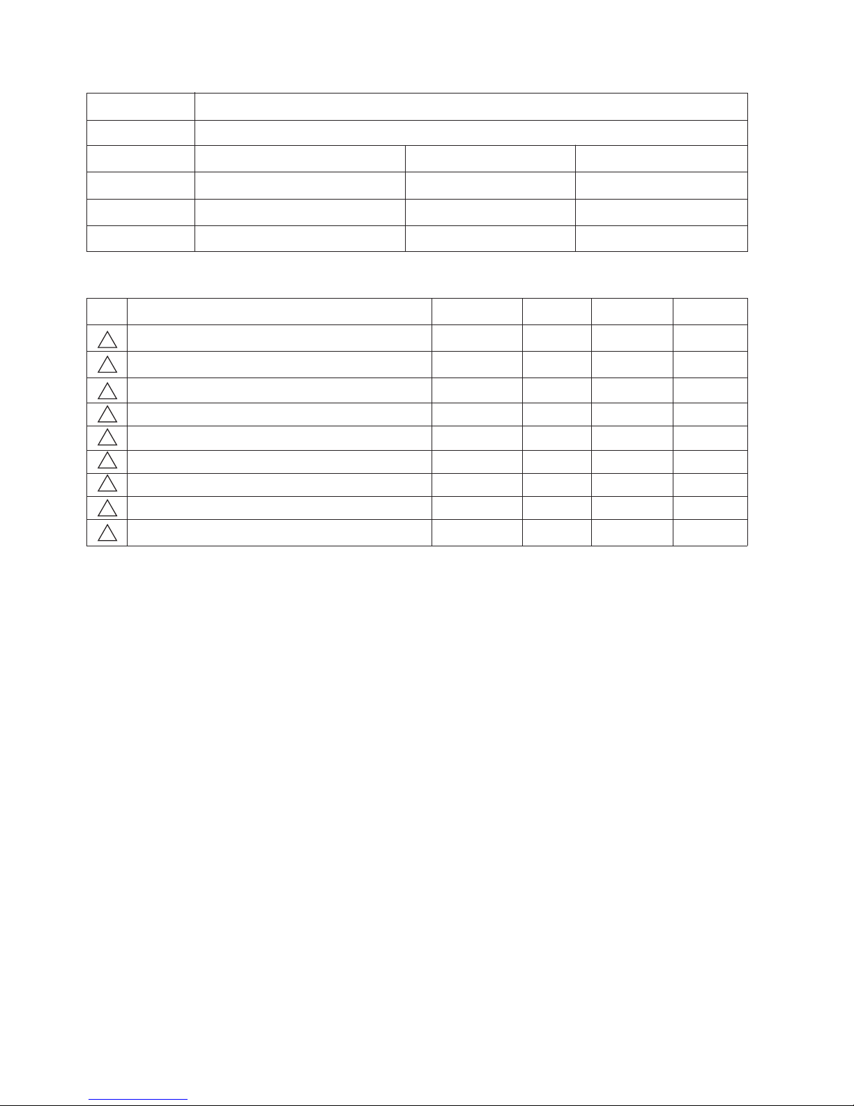
Slide Switch
Handle Button
Telescopic
Wand
Wand
Button
Hose
Fitting Hook
Power Cord
(Not Shown)
Cord Reel
Button
Suction Inlet
Latch
Performance Indicator
Crevice Tool
Dusting/Upholstery Tool
Air-Turbine
Brush Nozzle
Pile Adjustment
3.1 MODEL 721.24195S
DESCRIPTION
SPECIFICATIONS
• POWER SOURCE: ON RATING PLATE
• POWER CONTROL:
MAIN: SLIDE CONTROL ON HANDLE
• CAPACITY: 2.5
l
• CORD LENGTH: 5.3 m
• HOSE LENGTH: 1.5 m
• NET WEIGHT: 4.7 kg
• PACKING WEIGHT: 9.2 kg
• NET DIMENSION: 296 x 369 x 248 (W x D x H)mm
• PACKING DIMENSION: 330 x 579 x 330(W x D x H)mm
• ATTACHMENTS
FLEXIBLE HOSE ASSY ............................................1EA
TELESCOPIC WAND ................................................1EA
AIR-TURBINE BRUSH NOZZLE ...............................1EA
DUSTING/UPHOLSTERY TOOL ...............................1EA
CREVICE TOOL ........................................................1EA
A
TTACHMENTS
Page 6
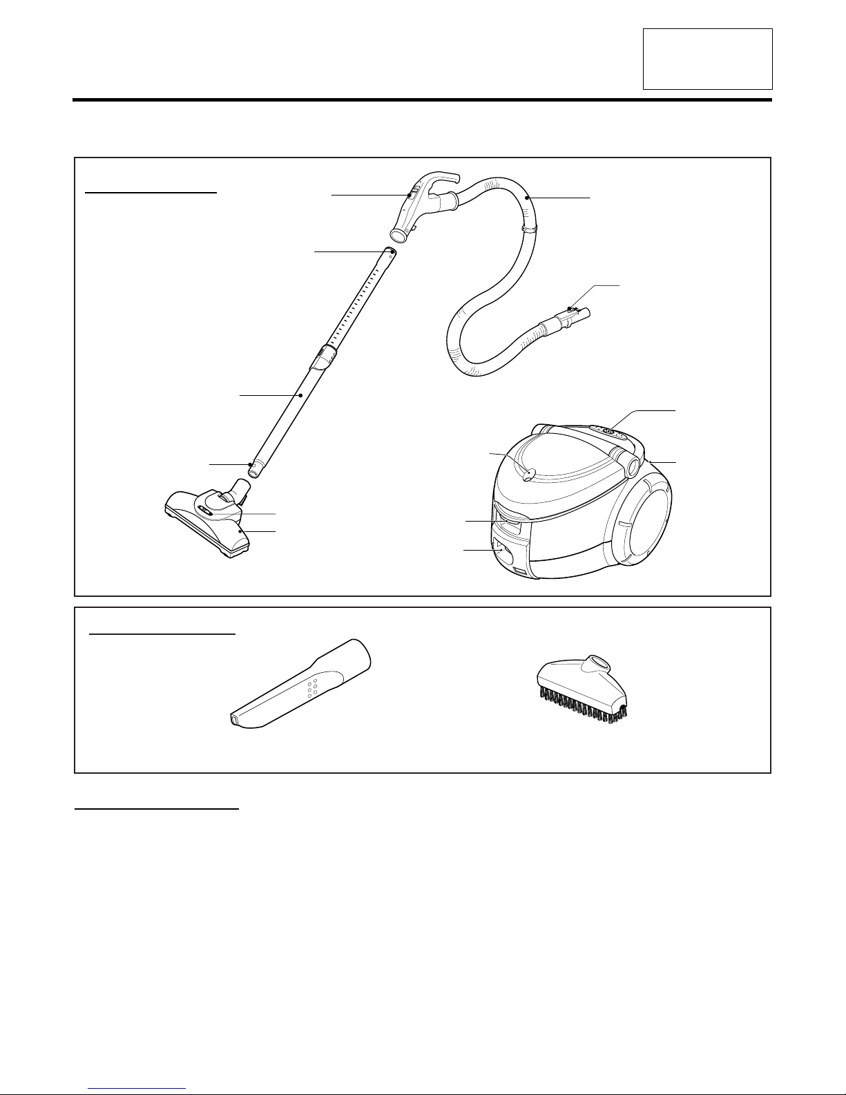
• Almost all the parts of this vacuum cleaner can be
assembled with a screw driver and each connecting
component easily fits each other.
Disassemble one by one referring to the exploded view.
• If possible, don’t disassemble except for the necessary
parts. It is not necessary to disassemble the parts that are
not detailed in the exploded view.
4.1 Filter Cover Assembly Replacement
1) Grasp body base and open filter cover.
4.2 Indicator Assembly Replacement
4.3 Body Cover Assembly Replacement
1) Open the filter cover and remove the two screws and
remove the four screws fastening the body base.
2) Lift body cover in the direction of the arrow.
4. DISASSEMBLY
NOTE: Before attempting to service or adjust any part of the vacuum cleaner, disconnect the electrical power supply cord from
the wall outlet.
5
MODEL 721.24195S
Page 7
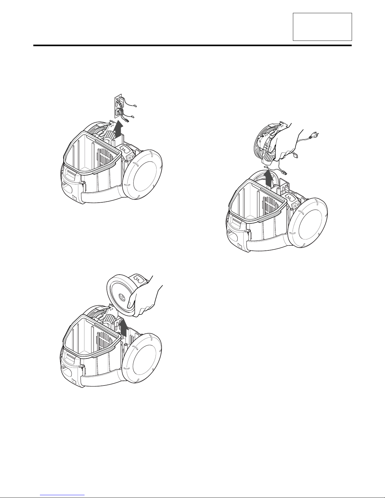
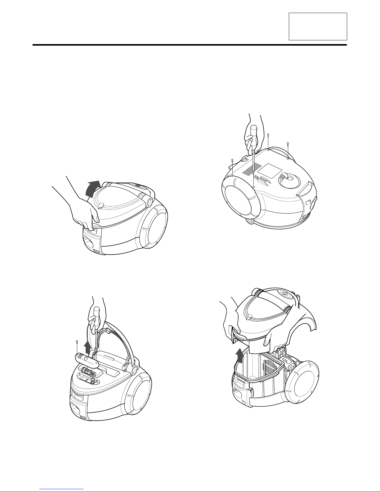
4.4 P.W.B ASS’Y Replacement.
1) Lift the P.W.B ASS’Y in the direction of the arrow.
4.5 Motor Assembly Replacement
• Lift the motor assembly in direction of the arrow after
stripping off the lead wires.
4.6 Cord reel assembly replacement
1) Lift the cord reel assembly from the body base in direction
of the arrow.
2) Strip off the lead wires.
MODEL 721.24195S
6
Page 8
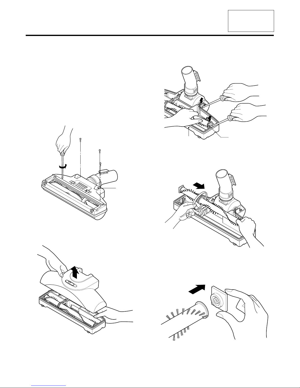
4.7 Belt Changing and Brush Cleaning
• Disconnect cleaner from electrical outlet. Check and
remove hair, string and lint build-up frequently in the AirTubine Brush Nozzle brush and brush support areas. If
build-up becomes emcessive, disconnect Air-Tubine
Brush Nozzle from Telescopic wand.
TO REMOVE BELT
1) Turn Air-Tubine Brush Nozzle upside down.
2) Unscrew the four Air-Tubine Brush Nozzle cover screws.
3) Turn Air-Tubine Brush Nozzle rear side up and tilt cover
forward from back until front snaps free.
4) Carefully insert and lift screwdriver at each brush support
to free brush from base.
5) Remove worn belt.
6) Slide brush supports off to check and clean brush support
areas. See PARTS LIST for picture of complete brush
assembly.
Wheel
Base
Brush Support
MODEL 721.24195S
MODEL 721.24195S
7
Page 9

TO REPLACE BELT:
1) Install brush supports onto brush.
2) Install new belt in belt groove on the brush, then over the
fan shaft. Be sure belt is between the belt guards.
3) Insert each support into its base slot.
4) Push cover and base together.
8
MODEL 721.24195S
Brush
Brush support
Belt
Guard
Belt Groove
Belt
Fan Shaft
Page 10

9
MODEL 721.24195S
5. TROUBLE SHOOTING
SOLUTIONCAUSE
Check the power source
CHECKING
Poor plug insertion
Power cord cut
Interior lead wire cut
Motor(stator armature) coil cut
or damaged
Poor contact carbon brush
defaced
Motor armature cut
Ball bearing defacement
Impeller hindrance
(Caused by foreign matters)
Insert again
Repair or exchange
Exchange the lead wire
Exchange the motor
Exchange or repair
Poor switch contact point Exchange the switch
Exchange the motor
Exchange the motor
Remove the foreign matters
Normal
1) SWITCH ON BUT MOTOR DOSE NOT RUN.
2) SWITCH ON, MOTOR DOES NOT RUN BUT BUZZES.
Page 11

10
MODEL 721.24195S
Poor connection
Poor switch
Carbon brush defaced
Motor armature cut
Foreign matters attached to
the impeller
Low voltage
Hose and extension wands are
clogged with foreign matters
Filter bag or cloth bag is filled
with inhaled foreign matters
Repair
Exchange the switch
Exchange the carbon brush
or the motor
Exchange the motor
Remove the foreign matters
Inquire to the power utility
company
Remove the foreign matters
in the hose or extension wands
Low rotation speed
Motor turns normally,
but suction power is weak
Rotating switch is on low
mode
Rotate it with clock-wise so
power is increasd
Remove the foreign matters
or exchange the filter bag or
clean the cloth bag
3) SWITCH OFF BUT MOTOR RUNS.
4) WEAK SUCTION POWER
Page 12

11
MODEL 721.24195S
Poor cord, lead wire
Poor carbon brush rectified
Poor electric connector
or receiver
Exchange cord, lead wire
Exchange the carbon brush
or the motor
Repair the electric connector
or receiver
Poor capacitor
Exchange the capacitor
Bent connection parts
Poor connection
(Caused by foreign matters)
Exchange the parts
Remove the foreign matters
and reconnect
Loose parts
Unbalanced motor assembly
Foreign matters are attached
to the impeller
Poor carbon brush rectification
Secure firmly
Exchange or repair the motor
Remove the foreign matters
Exchange the carbon brush
or the motor
Armature is cut or foreign
matters attached
Exchange motor
Remove foreign matters
5) VIBRATION NOISES
6) RADIO, TV RECEPTION DISTURBANCE
7) IMPROPER TUBE OR NOZZLE CONNECTION
Page 13

12
MODEL 721.24195S
6.BLOCK DIAGRAM/SCHEMATIC DIAGRAM/CIRCUIT DIAGRAM
6.1 MODEL 721.24195S
WIRING DIA
GRAM
SCHEMATIC DIAGRAM
WH
BL
BL
BK
BL
BR
TS
P.W.B. ASS'Y
MOTOR
C/REEL ASS'Y
BR
BL
SLIDE VOLUME S/W
FLEXIBLE HOSE ASS'Y
M
C5
0.47 F
100V
C1
0.1 F
630V
R2
220
1/2W
R1
100
1/2W
R4
470
1/2W
Transformer
T.S
R12
470K
R12-1
470K
R7
10K
R11
10K
R10
100
R6
22K
IC1
Opto-triac
TLP762
16
4
G
SS
_
+
T1
TRIAC
T2
2
VR1
VR1
20K
Q2
A1015
D5
1N4148
Q1
C3198
BD1
DF01M
R8
1K
R9
100
Page 14

13
7.POWER AND CONTROL CIRCUIT BOARD
7.1 MODEL 721.24195S
COMPONENT SIDE SOLDER SIDE
MODEL 721.24195S
Page 15

14
MODEL 721.24195S
8.EXPLODED VIEW/REPLACEMENT PARTS LIST
1
2
12
3
5
15
17
13
11
10
14
16
4
8
6
7
9
8.1 MODEL 721.24195S
EXPLODES VIEW
MODEL 721.24195S
Page 16

15
MODEL 721.24195S
34 39
40
26
18
31
32
27
29
33
21
30
19
20
22
23
28
25
24
MODEL 721.24195S
35
36
38
37
Page 17

16
MODEL 721.24195S
MODEL 721.24195S
41
Page 18

17
MODEL 721.24195S
MODEL 721.24195S
42
48
49
43
50
52
54
51
44
45
46
47
Page 19

18
MODEL 721.24195S
MODEL 721.24195S
77
60
61
62
63
66
78
65
64
59
56
58
70
75
76
73
74
68
57
67
71
72
69
Page 20

19
MODEL 721.24195S
LOCATION NO.
DESCRIPTIONPART NO. REMARKS
MODEL 721.24195S
REPLACEMENT PARTS LIST
1 3550FI1759K ACCESSORY COVER
2 3550FI1758H FILTER COVER
3 3550FI3868H INDICATOR COVER
4 3I23019L INDICATOR
5 1TPL0302418 SCREW 3*8
6 5203FI2071A DUST BRUSH ASS'Y
7 5058FI3593A CREVICE TOOL
8 4026FI3691G LATCH
9 4970FI4260A LATCH SPRING
10 3650FI2422A HANDLE
11 4370FI3678A HANDLE SHAFT
12 3550FI1757B BODY COVER
13 5020FI3806B CORD WINDING BUTTON
14 4I70024A CORD WINDING SPRING
15 4510FI2441A CORD WINDING LEVER
16 1TPL0402818 SCREW 4*12
17 5230FI3558B EXHAUST FILTER
18 3040FI1525A BODY BASE
19 3920FI1289A DUST SEAL PACKING
20 4661FI1008H WHEEL ASS'Y
21 *5231FI2390J DUST BAG
22 4480FI3752A FILTER SETTING HOOK
23 4I23017A FILTER SETTING HOOK SPRING
24 3550FI1756B FRONT COVER
25 3I23038G TERMINAL PLATE ASS'Y
26 3I23009L TERMINAL SUPPORTER
27 1TPL0402818 SCREW 4*12
28 4036FI3036A TERMINAL PACKING
29 5230FI3248F MOTOR SAFETY FILTER
30 4441FI3608D CASTER ASS'Y
31 4I22017A ROLLER
32 4I22094A ROLLER SHAFT
33 1TPL0403318 SCREW 4*20
34 6871FX2130G PWB ASS'Y
35 3920FI3766A MOTOR MOUNT PACKING
36 4681FI2373Y MOTOR
37 3940FI3646A ABSORBING SPONGE
38 3920FI3859A MOTOR SEAL PACKING
39 5230FI3557C EXHAUST FILTER
40 3940FI3311B EXHAUST SPONGE
Page 21

MODEL 721.24195S
MODEL 721.24195S
REPLACEMENT PARTS LIST
LOCATION NO.
DESCRIPTIONPART NO. REMARKS
41
42
43
44
45
46
47
48
49
50
51
52
53
55
58
57
59
60
61
62
63
64
65
66
67
68
69
70
71
72
73
74
75
76
77
78
4687FI1468H CORD WINDING ASS'Y
AEM30953708 HOSE ASS’Y
4940FI3431A SLIDE KNOB
3500FI3617B SWITCH BOARD
1TPL0302416 SCREW 3*8
3550FI1511D HANDLE COVER
3650FI1474F GRIP HANDLE
4930FI2360T HOSE
5200FI2357M FITTING PIPE
FITTING HOOK
4I23028A HOOK SPRING
3I23013J
3550FI2358J F/PIPE COVER
5201FI2485A TELESCOPIC WAND
3040FI1502B NOZZLE BASE
5249FI1414E NOZZLE ASSEMBLY, TURBINE
3550FI1637B NOZZLE COVER
4940FI3736A PILE ADJUSTMENT
5200FI2497B SUCTION PIPE
1KZZFI3001B KEY
4930FI2452B SUCTION PIPE HOLDER
5901FI2001A FAN ASSEMBLY
4280FI3003A BEARING BALL
4581FI3001A ROLLER ASSY
4370FI3669A SHAFT
4581FI3002A ROLLER ASSY
4370FI3670A SHAFT
3550FI2540B COVER FLOW
4820FI2399B NOZZLE BUMPER
5882FI2001A SWEEPER
4766FI3709A FELT
3740FI3712A PROTECTOR(MECH)BELT
3740FI3711A PROTECTOR(MECH)BELT
4280FI3004A BEARING BALL
5973FI2001A BRUSH
4400FI3349A BELT
1TPL0403116 SCREW 4*16
20
Page 22

21
MEMO
Page 23

22
MEMO
Page 24

23
MEMO
Page 25

P/No.: 3828FI9002W
 Loading...