

Page 1
INSTALLATION INSTRUCTIONS FOR YOUR NEW
FREE-STANDING
ELECTRIC RANGE
Before you begin - Read these instructions completely and carefully.
IMPORTANT - Save these instrucUons for local Inspector's use.
IMPORTANT - OBSERVE ALL GOVERNING CODES AND ORDINANCES.
Note to Installer. Be sure to leave these instructions with the Consumer.
Note to Consumer - Keep these Instructions with your Use and Care Book for future reference.
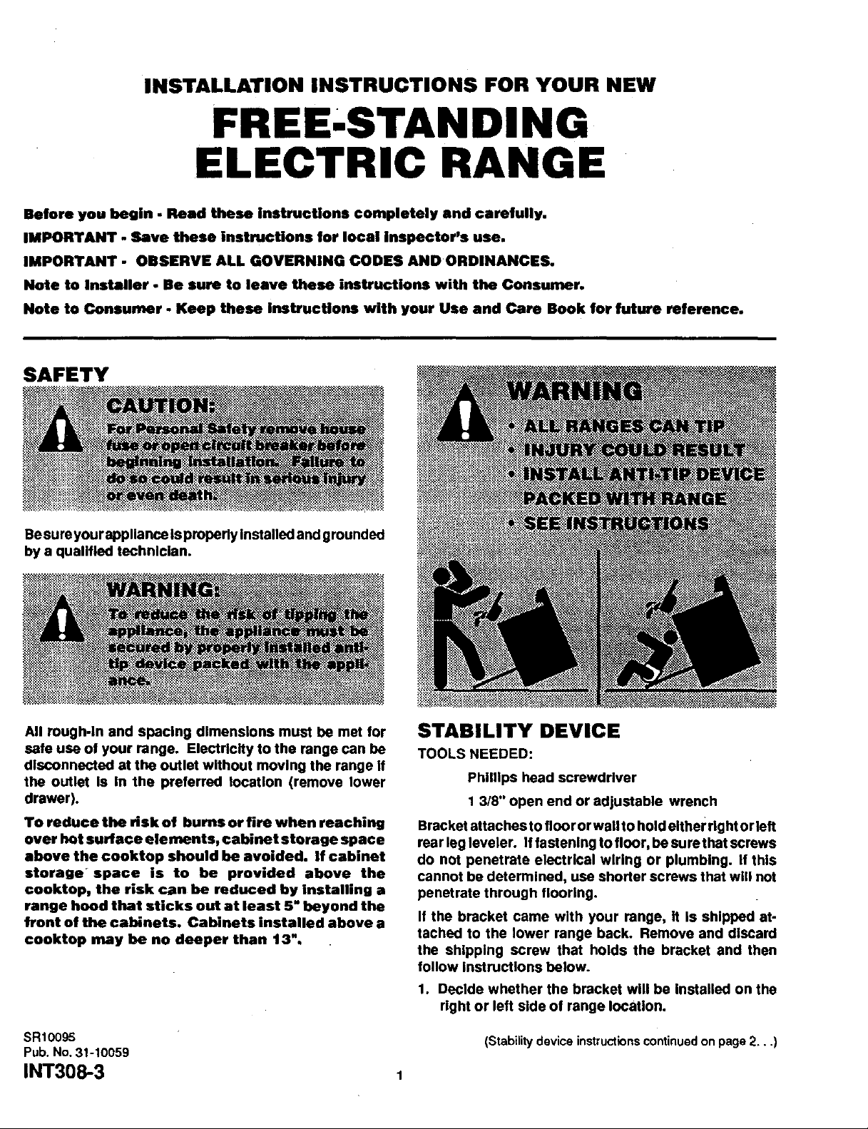
SAFETY
Besureyourappllance isproperly Installed and grounded
by a qualified technician.
All rough-In and spacing dimensions must be met for
safe use of your range. Electricity to the range can be
disconnected at the outlet without moving the range If
the outlet Is In the preferred tocatlon (remove lower
drawer).
To reduce the risk of bums or fire when reaching
over hot surface elements, cabinet storage space
above the €ooktop should be avoided. If cabinet
storage ° space is to be provided above the
€ooktop, the risk can be reduced by Installing a
range hood that sticks out at least 5" beyond the
front of the cabinets. Cabinets installed above a
cooktop may be no deeper than 13".
STABILITY DEVICE
TOOLS NEEDED:
Phillips head screwdriver
1 3/8" open end or adjustable wrench
Bracket attaches to floor or wall to hold either rightor left
rear leg leveler. Iffastening to floor, be surethat screws
do not penetrate electrical wiring or plumbing. If this
cannot be determined, use shorter screws that will not
penetrate through flooring.
If the bracket came with your range, It Is shipped at-
tached to the lower range back. Remove and discard
the shipping screw that holds the bracket and then
follow instructions below.
1. Decide whether the bracket will be Installed on the
right or left side of range location.
SR10095
Pub. No. 31-10059
INT308-3 1
(Stability device instructionscontinued on page 2,..)
Page 2
(Stability device instructionscontinued...)
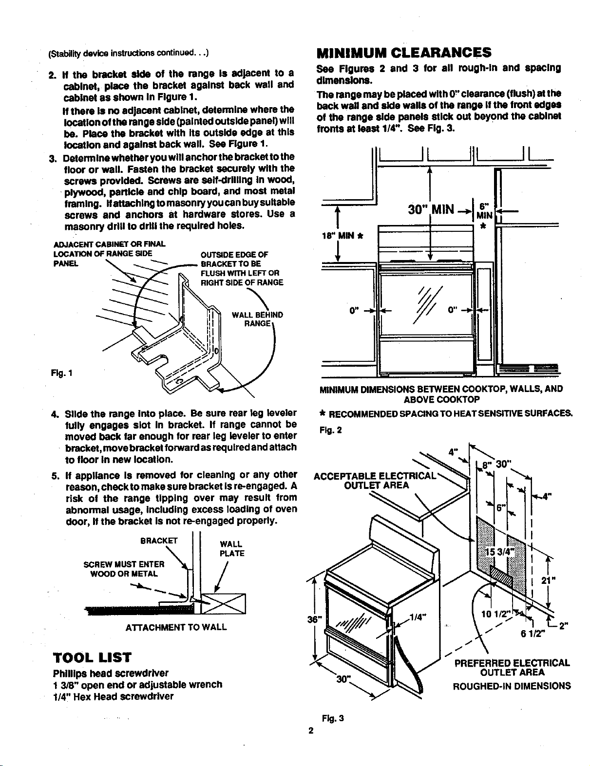
2. If the bracket side of the range Is adjacent to s
cabinet, place the bracket against beck wall and
cabinet as shown In Figure 1.
If there Is no adjacent cabinet, determine where the
location of the range side (painted outside panel) will
be. Plane the bracket with Its outside edge at this
location and agalnet back wall. See Figure 1.
3. Dstermlne whether you will anchor the bracket to the
floor or wall. Fasten the bracket securely with the
screws provided. Screws are self-drllllng In wood,
plywood, particle and chlp board, and most metal
tramlng. Ifattachlng to masonry you can buysultable
screws and anchors at hardware stores. Use a
masonry drill to drill the required holes.
ADJACENT CABINET OR FINAL
LOCATION OF RANGE SIDE
pANEL
__HTBRACKET TO BE
OUTSIDE EDGE OF
FLUSH_IIErr_ LEFT ORE
MINIMUM CLEARANCES
See Figures 2 end 3 for ell rough-In and spacing
dimensions.
The range may be placed with 0" clearance (flush) at the
back wall and side walls of the range if the front edges
of the range side panels stick out beyond the cabinet
fronts st isast 1/4". See Fig. 3.
11L
18" MIN *
1
m
_'---I.-_ _ \l, ti !i!l WALLBEHIND
Fig. 1
4. Slide the range Into place. Be sure rear leg leveler
gully engages slot In bracket. If range cannot be
moved back far enough for rear leg leveler to enter
bracket, move bracket forward as redulred and attach
to floor In new lOCation.
5. If appliance Is removed for cleaning or any other
reason, check to make sure bracket Is re-engaged. A
risk of the range tipping over may result from
abnormal usage, Including excess loading of oven
door, If the bracket Is not re-engaged properly.
BRACKET
SCREWMUSTENTER%'_
WOODOR METAL |
WALL
PLATE
/
O" ,-I _.-
i
MINIMUM DIMENSIONSBETWEENCOOKTOP,WALLS,AND
ABOVE COOKTOP
* RECOMMENDED SPACING TO HEAT SENSITIVE SURFACES.
Fig. 2
ACCEPTABLE ELECTRICAL_
OUTLET AREA
r---
ATrACHMENT TO WALL
TOOL LIST
Phillips head SCrewdriver
1 3/8" open end or adjustable wrench
1/4" Hex Head screwdriver
I" 2"
/ 61/2"
/"
PREFERRED ELECTRICAL
OUTLET AREA
ROUGHED-IN DIMENSIONS
Fig.3
2
Page 3

PREPARATION
Remove all tape and packaging. Remove clear plastic
film that covers some parts (around glass oven doors,
side trim) and any tape or packaging from inside the
oven,
Remove the accessory pack from the oven.
Check to see if any range parts have come loose during
shipping.
ELECTRICAL REQUIREMENTS
This appliance must be supplied with the proper voltage
and frequency, and connected to an Individual, properly
grounded branch circuit, protected bya circuit breaker or
time delay fuse, as noted on raUng plate.
Wiring must conform to National Electrical Cedes. If the
electric service provided does not meet the above
specitlcatlons, call a licensed electrician.
You can get a copy of the National Electrical Code, ANSI/
NFPA No. 70-Lstest Edition by writing:
National Fire Protection Association
Battery March Park
Quincy, MA 02269
Effective January 1, 1996, the National Electrical Code
requires that new or rewired construction utilize a four-
conductor connection toanelectric range. When installing
an electric range In a new construction, follow the
instructions In NEW CONSTRUCTION AND FOUR-
CONDUCTOR BRANCH CIRCUIT CONNECTION.
ifyou failto wire you rrange inaccordance withgoverning
codes, you may create a hazardous condition.
You must use a three-wire, single-phase AC 120/240 Volt
or 208Y/120 Volt, 60 Hertz electrical system to operate
your range.
Use #8 gauge wire and 40 Amp fuse or circuit breaker for
120/240 Volt and 208Y/120 Volt systems.
The range connector block Is approved for copper wire
connection only. If you are connecting to aluminum
house wiring, you must use special UL approved
connectors for joining copper to aluminum.
TO MAKE ELECTRICALCONNECTION:
Remove the junction block access cover (on
range back). See Fig. 4A or Fig. 4B. Some
models will have a one.piece wire cover as
shown in Fig. 4B. When reinstalling the one-
piece wire cover_ make sure that wire does not
become pinched between wire cover and
mainback.
Allnewconstmctions, mobile homes andInstallations
where local codes do not allow grounding through
neutral, require a four-wire flexible cord kit. If the
range is rated between 8,750 and 16,500 watts, the
cord kit must be rated for 40 amps-125/250 volts. If
the range Is rated between 16,501 and 22,500 watts
the cord kit must be rated for 50 amps-125/250 volts.
For existing construction, a thrse-wlre flexible cord
kit may be used, and the same ratings apply as
described above.
When using a cord kit rated 40 Amps, remove
the next to outermost knockout (1 3/8" diameter) In
the connection plate. Likewise, when using a
cord kit rated 50 Amps, remove the outermost
knockout (1 3/4" diameter) In the plate.
You must use a clamp or strain relief to hold thecord.
Terminations must beeit her closed loop terminals or
open end spade lugs.
FOUR-WIRE CORD
CONNECTION KIT
Remove the screws on the junction bloc k studs.
Remove the ground screw, then remove the ground
strap.
Install the tour-wire cord kit and strain rellet In the
hole In the connection plate.
Connect the red and black leads to the outside
terminals and white lead to the center terminal.
Attach the green lead below the junction block with
the ground screw that was removed earlier.
Push the cord upward (to relieve strain), while
tightening the strain rellet clamp.
SCREW
GROUND
SCREW
Fig. 4A Fig. 4B
CONNEC_ON
PLATE
3
STRAIN
RELIEF
CLAMP
Page 4

THREE-WIRE CORD
CONNECTION KIT
Remove the screws on the junction block studs.
Install the thrse-wlre cord and the strain relief In the hole
In the connection plate.
Connect the red and black leads to the outer terminals
and the white lead to the center terminal.
Push the cord upward (to relieve strain), while tightening
the strain relief clamp.
If local codes require an ungrounded neutral.
Remove ground strap.
Fasten the white wire to the center terminal
Use grounding terminal or lead to ground unit In
accordance with local codes.
GROUNDED
SCREW
TERMINAL
GROUND STRAP
GROUNDSCREW
LEVEL THE RANGE
Using the wrench, back out the four leg levelers st least
two turns. See your Installation guide for more levallng
Information before positioning range.
The range must be level for proper cooking and baking.
Install the oven racks (see Owner's Manual for
iestructlona).
CONNECTION
PLATE
OVEN DOOR REMOVAL
Before Installing the range, you may remove the oven
door to lessen the welg ht of the unit. DO NOT lift unit by
door handle.
To remove oven door.
1. Open the door to the stop posttion. See Fig. 5A.
2. Grasp the door at each side and lift up and off the
hinges. See Fig. 5B.
Fig. 5A
STOP POSITION HINGE
Fig. 5B
Use a 13/8" open end wrench or anadjustable wrench to
equally back out the four leg levelers two or three turns
each.
SR10095
Pub.No.31-10059
INT30_3
Recyc_Pa_
4
Printed in LaFayette, Georgia --
 Loading...