

N9MP1 & N9MP2
*9MPD
* Denotes Brands (C, H, T)
FAN ASSISTED, DIRECT
VENT GAS FURNACE
SAFETY REQUIREMENTS
Recognizesafetyinformation. Thisisthesafety--alertsymbol!. When yousee thissymbolon thefurnaceandininstructions manualsbealertto
the potential for personal injury.
Understand the signal words DANGER, WARNING, or CAUTION. Thesewords are used with the safety--alert symbol. DANGER identifies the
most serious hazards, those that will result in severe personal injury or death. WARNING signifies a hazard that could result inpersonalinjuryor
death. CAUTION is used to identify unsafe practices that could result in minor personal injury or product and property damage.
Installing and servicing heating equipment can be hazardous due to gas and electrical components. Only trained and qualified personnel should
install, repair, or service heating equipment.
Untrained service personnel can perform basic maintenance functions such as cleaning and replacing air filters. All other operations must be
performedbytrained servicepersonnel. Whenworkingon heatingequipment,observeprecautionsintheliterature,ontags, andon labelsattached
to or shipped with the unit and other safety precautions that may apply.
Follow all safety codes. In the United States, follow all safety codes including the current edition National Fuel Gas Code (NFGC) ANSI
Z223.1--2002/NFPANo. 54--2002. In Canada,refertothe current editionofthe National StandardofCanada NaturalGasand PropaneInstallation
Code (NSCNGPIC) CSA B149.1--00. Wear safety glasses and work gloves. Have fire extinguisher available during start--up and adjustment
procedures and service calls.
Theseinstructions coverminimumrequirementsandconformtoexistingnationalstandardsandsafetycodes. Insomeinstances,theseinstructions
exceedcertainlocalcodesandordinances,especiallythosethat maynothavekeptup withchangingresidential construction practices. Werequire
these instructions as a minimum for a safe installation.
International Comfort Products Corporation (USA)
Lewisburg, TN 37091 U.S.A.
1. Safe Installation Requirements 3.................
2. Installation 4................................
3. Combustion & Ventilation Air 7..................
4. Vent & Combustion Air Piping 10................
5. Gas Supply and Piping 26......................
6. Electrical Wiring 30...........................
Table of Contents
!
Electric Shock Hazard
Turn Off All Power Before Servicing.
Failure to do so can result in death,
personal injury and/or property
damage.
INSTALLER: Affix these instructions
on or adjacent to the furnace.
CONSUMER: Retain these
instructions for future reference.
7. Ductwork and Filter 30........................
8. Checks and Adjustments 33....................
9. Furnace Maintenance 35.......................
10. Sequence of Operation & Diagnostics 35..........
11.Concentric VentTermination 39.................
TechSupport and Parts 43........................
!
FIRE OR EXPLOSION HAZARD
This furnaceis not designed for use in mobile
homes, trailers or recreational vehicles.
Such use could result in death, bodily injury
and/or property damage.
PrintedinU.S.A. 4/28/2003 440 01 1020 (02)
START--UP CHECK SHEET
For 90+ Furnace
(Keep this page for future reference)
Dealer Name:
Address: Business Card Here
City, State(Province), Zip or Postal Code:
Phone:
Owner Name:
Address:
City, State(Province), Zip or Postal Code:
Model Number:
Serial Number:
Type of Gas: Natural: LP:
Which blower speed tap is used?
(Heating)
Temperature of Supply Air: (°F) or(°C)
(Cooling)
Manual Gas Shut--Off Upstream
of Furnace/Drip--Leg? YES
Condensate Drain Connected? YES NO
Condensate Drain Trapped? YES NO
Transition Pressure switch hose relocated for U/D/H
Application? YES
Blower Speed Checked? YES NO
All Electrical Connections Tight? YES NO
Gas Valve OK? YES NO
Measured Line Pressure When Firing Unit:
Calculated Firing Rate:(See Checks and Adjustments Sec-
tion).
NO
NO
Temperature of Return Air: (°F) or(°C)
Rise (Supply Temp.--Return Temp.): (°F) or(°C)
Filter Type and Size:
Fan “Time ON” Setting:
Fan “Time OFF” Setting:
Dealer Comments:
2
Temperature Rise (supply--return temperature):(°F)
Measured Manifold Gas Pressure:
Static Pressure (Ducts): Supply Air Return
Date of Start--Up:
CO ?
CO2 ?
440 01 1020 02

1. Safe Installation Requirements
!
DEATH, PERSONAL INJURY AND/OR PROPERTY
DAMAGE
Failure to carefully read and follow all instructions
in this manual can result in furnace malfunction,
death, personal injury and/or property damage.
Installation or repairs made by unqualified persons
can result in hazards to you and others. Installation
MUST conform with local codes or, in the absence
of local codes, with codes of all governmental
authorities having jurisdiction.
The information contained in this manual is
intended for use by a qualified service technician
who is experienced in such work, who is familiar
with all precautions and safety proceduresrequired
in such work, and is equipped with the proper tools
and test instruments.
NOTE: This furnace is design--certified by the CSA International
(formerly AGA and CGA) for installation in the United States and
Canada.Refertotheappropriatecodes,alongwiththismanual,for
proper installation.
· Use only the Type of gas approved for this furnace (see
RatingPlateonunit). Overfiringwillresultin failure ofheat
exchanger and cause dangerous operation. (Furnaces
can be converted to L.P. gas with approved kit.)
· Installthisfurnaceonlyinalocationandposition as speci-
fied in “2. Installation” of these instructions.
· Provideadequatecombustion andventilationairto thefur-
naceasspecifiedin“3. Combustion and VentilationAir” of
these instructions.
· Combustionproducts must be discharged outdoors. Con-
nectthisfurnacetoanapprovedventsystemonly, asspecified in “4. Vent and Combustion Air Piping” of these
instructions.
· Never test for gas leaks with an open flame. Use a com-
mercially available soap solution made specifically for the
detection of leaks to check all connections,as specified in
“6. Gas Supply and Piping, Final Check” of these instructions.
· Always install furnace to operate within the furnace’s in-
tended temperature--rise range with a duct system which
hasanexternalstaticpressurewithintheallowablerange,
asspecifiedin“TechnicalSupportManual”oftheseinstructions.
· When a furnace is installed so that supply ducts carry air
circulated by the furnace to areas outside the space containingthefurnace,thereturnairshallalsobehandledbya
duct(s) sealed to the furnace casing and terminating outside the space containing the furnace.
· A gas--fired furnace for installation in a residential garage
mustbe installedass pecified in“2.Installation” ofthesein structions.
· This furnace is not to be used for temporary heating of
buildings or structures under construction.
· Thisfurnaceis NOTapprovedfor installationinmobile
homes, trailers or recreation vehicles.
· Seal around supply and return air ducts.
· Install correct filter type and size.
· Unit MUST be installed so electrical components are pro-
tected from direct contact with water.
Safety Rules
Your unitisbuilttoprovidemanyyearsofsafeanddependableser vice providing it is properly installed and maintained. However,
abuse and/or improper use can shorten the life of the unit and
create hazards for you, the owner.
A. The U.S. Consumer Product Safety Commission recom-
mends that users of gas--burning appliances install carbon
monoxidedetectors. There can be various sources of carbon
monoxidei n abuildingor dwelling.Thesourcescouldbe gas-fired clothes dryers, gas cooking stoves, water heaters, furnaces, gas --fired fireplaces, wood fireplaces, and several
other items.
Carbon monoxide can cause serious bodily injury and/or
death. Carbon monoxide or “CO” is a colorless and odorless
gasproducedwhenfuelis not burned completely or whenthe
flame does not receive sufficient oxygen.
Therefore, to help alert people of potentially dangerous carbon monoxide levels, you should have c arbon monoxide detectors that are listed by a nationallyrecognized agency (e.g.
UnderwritersLaboratoriesorInternationalApprovalServices)
installed and maintained in the building ordwelling (see Note
below).
B. There can be numerous sources of fire or smoke in a building
or dwelling. Fire or smoke can cause serious bodily injury,
death, and/or property damage. Therefore, in order to alert
people of potentially dangerous fire or smoke, you should
have fire extinguisher and smoke detectors listed by UnderwritersLaboratoriesinstalledandmaintainedinthebuildingor
dwelling (see Note below).
Note: The manufacturer of your furnace does not test any detec-
tors and makes no representations regarding any brand or
type of detector.
C. To ensure safeandefficientoperationof your unit,youshould
do the following:
1. Thoroughly read this manual and labels on the unit. This
willhelp you understand how your unit operates and the hazards involved with gas and electricity.
2. Do not use this unit if any part has been under water. Immediatelycalla qualifiedservicetechniciantoinspect theunit
andtoreplace anypartofthecontrolsystemandanygascon trol which has been under water.
3. Never obstruct the vent grilles, or any ducts that provide
air to the unit. Air must be provided for proper combustion
and ventilation of flue gases.
Frozen Water Pipe Hazard
!
FROZEN AND BURST WATER PIPE HAZARD
FaiIure to do so may result in burst water pipes, serious
property damage and/or personal injury.
Furnace may shut down. Do not leave your home
unattended for long periods during freezing weather
without turningoffwater supplyanddraining waterpipes
or otherwise protecting against the risk of frozen pipes.
Your furnace is designed solely to provide a safe and comfortable
living environment. The furnace is NOT designed to ensure that
water pipes will not freeze. It is equipped with several safety devices that are designed to turn the furnace off and prevent it from
restarting in the event of various potentially unsafe conditions.
440 01 1020 02
3
If your furnace remains off for an extended time, the pipes in your
home could freeze and burst, resulting in serious water damage.
Watermaycreateaconditioninwhichmoldcangrowinyourhome.
Certain types of mold have been reported to cause respiratory
problemsorotherserioushealthrisks.Remedialactions,including
immediately drying all wet items, should be taken quickly to help
prevent the development of mold in your home.
If the structure will be unattended during cold weather you should
take these precautions.
1. Turnoff thewatersupplyto thestructureanddrain thewater
lines if possible and add an antifreeze for potable water to
drain traps and toilet tanks. Open faucets in appropriate
areas.
-- o r --
2. Have someone check the structure frequently during cold
weather to make sure it is warm enough to prevent pipes
from freezing. Instruct them on a service agency to call to
provide service, if required.
-- o r --
2. Installation
3. Installareliable remotesensingdevice thatwillnotify somebody of freezing conditions within the home.
Winter Shutdown
Ifyou go away during the winter months and do notleavetheheat
oninyour home,theplastictransition boxandthecondensatetrap
on the furnace must be protected from freeze damage.(See
Figure 8 trough Figure 17)
5
1. Disconnect the
tingthatislocateddownstreamofthecombustionblower.Insert a funnel into the hose and pour four(4) ounces of
sanitary type (RV) antifreeze into the condensate trap. Reconnectthe
fitting. Secure with the hose clamp.
2. Disconnect the
trap. Insert a funnel into the hose and and pour four(4)
ouncesofsanitarytype(RV)antifreezeintotheplastic Transition box. Squeeze the hose together near the end and
quicklyreconnectthe
condensate trap. Secure with the hose clamp.
When you return home, your furnace will be ready to start, as it is
not necessary to drain the antifreeze from the furnace.
/8² OD rubber hose from the vent drain fit-
5
/8² ODrubberhosetothestubonthe ventdrain
3
/4² OD rubber hose from the condensate
3
/4² ODrubber hose tothestubonthe
!
CARBON MONOXIDE POISONING HAZARD
Failure to properly vent this furnace or other appliances
can result in death, personal injury and/or property
damage.
ThisfurnacecanNOTbe common vented orconnectedto
any type B, BW or L vent or vent connector, nor to any
portion of a factory--built or masonry chimney. If this
furnace is replacing a previously common-vented
furnace, it may be necessary to resize the existing vent
andchimneytopreventoversizing problems for theother
remaining appliance(s). See Venting and Combustion Air
Checkin GasVentInstallation section.Thisfurnace MUST
be vented to the outside.
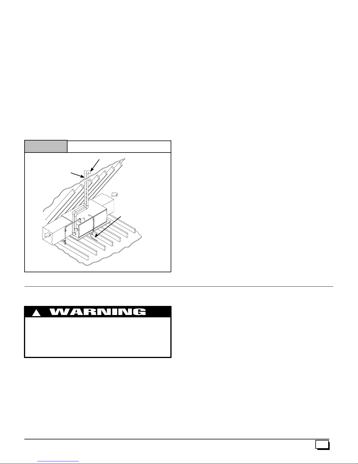
Location and Clearances
4. RefertoFigure 1 orFigure 2 fortypicalinstallationandbasic connecting parts required. Refer to Figure 4 for typical
horizontaldirect ventinstallationandbasicconnectingparts
required. Supply and return air p lenums and duct are also
required.
5. Iffurnaceisa replacement,itisusually besttoinstallthe furnace where the old one was. Choose the location or evaluatethe existinglocationbaseduponthe minimumclearance
and furnace dimensions (Figure 3).
CAUTION
Special precautions MUST be made if installing furnace in an
areawhichmaydropbelow freezing.Thiscancauseimproper
operation or damage to equipment. If furnace environment
hasthepotential of freezing, thedraintrapand drainline must
be protected. The use of electric heat tape or RV antifreeze is
recommendedforthese installations.(See“CondensateTrap
Freeze Protection Section”)
Do NOT operate furnace in a corrosive atmosphere
containing chlorine, fluorine or any other damaging
chemicals. Refer to Combustion & Ventilation Air section,
Contaminated Combustion Air.
Figure 1
*8² Min.
20¢ Max.
in same
atmospheric
zone
VentPipes MUST be
supportedHorizontally
and Vertically
T y pical Upflow Installation
Aluminum ornon-rusting shield recommended.(See
VentTermination Shielding fordimensions).
Couplingonendsof
exhaustpipe.Total
pipe &couplingoutside structure = 8²
*8² Min.
20¢ Max.
in sameatmospheric
zone
DISCHARGEAIR
Inlet Pipe(not
used onSingle
Pipe model)
4
* Increase minimumfrom8² to18² forcoldclimates (sustainedtemperatures below
0 ° F).
25--23--33
440 01 1020 02

Figure 2 T y pical Downflow Installation
preferred method is to use an angle iron frame bolted to the
rafters or joists.
See VentTermination
Shielding in VentSection.
*8² Min.
Inlet Pipe
(not usedon
Single Pipe
model)
VentPipes MUST be
supportedHorizontally
and Vertically
* Increase minimumfrom8² to 18² forcoldclimates (sustainedtemperatures
below0°F).
20¢ Max.
in same
atmospheric zone
Couplingoninside
and outsideofwall
to restrainvent pipe
8² Min.
*8² Min.
20¢ Max.
in same
atmosphericzone
25--23--33a
!
DEATH, PERSONAL INJURY AND/OR PROPERTY
DAMAGE HAZARD.
Failuretoproperlyinstall this furnacecanresultin death,
personal injury and/or property damage.
Do NOT operate furnace in a corrosive atmosphere
containing chlorine, fluorine or a ny other damaging
chemicals.
Refer to Combustion & Ventilation Air section,
Contaminated Combustion Air for combustion air
evaluation and remedy.
Installation Requirements
1. Install furnace level.
2. ThisfurnaceisNOTtobe usedfortemporaryheatofbuildings
or structures under construction.
3. Install the vent pipes as short as practical. (See Gas Vent
Installation section).
4. DoNOTinstall furnace directlyoncarpeting,tile or othercombustible material other than wood flooring.
5. Maintainclearance for fire safety and servicing. A front clearanceof30² is minimumforaccesstotheburner,controlsand
filter. See clearance requirements in Figure 3 or.
6. Use a raised base if the floor is damp or wet at times.
7. Residential garage installations require:
· Burnersandignitionsourcesinstalledat least 18² (457 mm)
above the floor.
· Furnace must be located or physically protected from pos-
sible damage by a vehicle.
8. Ifthefurnaceistobesuspendedfromthefloorjoistsinabasementora crawl space or the rafters in an attic, it is necessary
tousesteelpipestrapsoranangleiron frametoattachthefurnace. These straps should be attached to the furnace with
sheet metal screws and to the rafters or joists with bolts. The
This furnace may be used for construction heat provided that:
· Thefurnaceispermanentlyinstalledwithallelectricalwiring,
piping, venting and ducting installed according to these
installationinstructions. Areturnairduct isprovided,sealed
tothe furnacecasing,andterminatedoutsidethespace containingthefurnace. This prevents a negative pressure condition as created by the circulating air blower, causing a
flame rollout and/or drawing combustion products into the
structure.
· Thefurnaceiscontrolledbyathermostat. It may not be“hot
wired” to provide heat continuously to the structure without
thermostatic control.
· Cleanoutsideairis provided for combustion. Thisistomini-
mize the corrosive effects of adhesives, sealers and other
construction materials. It also prevents the entrainment of
drywall dust into combustion air, which can cause fouling
and plugging of furnace c omponents.
· The temperature of the return air to the furnace is no less
than55° F,withnoeveningsetback orshutdown. Theuseof
the furnace while the structure is under construction is
deemed to be intermittent operation per our installation instructions.
· Theairtemperatureriseiswithintherated riserange on the
furnace rating plate, and the firing rate has been set to the
rating plate value.
· The filters used to clean the circulating air during the
construction process must be either changed or thoroughly
cleaned prior to occupancy.
· The furnace, ductwork and filters are cleaned as necessary
to remove drywall dust and construction debris from all
HVAC system components after construction is completed.
Installation Positions
This furnace can be installed in an upflow, horizontal (either left or
right) or downflow airflow position. DO NOT install this furnace on
itsback.Fortheupflowposition,thereturnairductworkcanbeattached to either the left or right side panel and/or the bottom. For
horizontalanddownflow positions,thereturnair ductworkmustbe
attached to the bottom. The return air ductwork must never beattached to the back of the furnace.
Furnace Installation Considerations
Theinstallation ofthefurnacefora givenapplicationwilldictatethe
positionof thefurnace,theairflow,ductworkconnections,ventand
combustion air piping. Consideration must be given to the following:
CondensateTrapand Drain Lines
Thesupplied condensatetrapmustbeattachedtothefurnaceside
paneloneither theleftorrightside.Forhorizontal installations,the
draintrapisverticallyattachedto thesidepanel belowthefurnace.
A minimum clearance of 6² below the furnace is required for the
condensate trap. Downward slope of the condensate drain line
from the condensate trap to the drain location must be provided.
Adequatefreezeprotectionofthedraintrapand thedrainlinemust
be provided. See “Condensate Drain Trap” section for further de-
tails.
440 01 1020 02
5
Figure 3
Uni
t
Dimensions & Clearances
131/
F
AIR INTAKE
VENT (*9MPD)
TOP
H
Cabinet to Combustible Clearances
TOP BOT. RH LH BACK FRONT FLUE
1² 0² 0² 0² 0² 3² 0²
A
B
G
E
811/
LEFT SIDE
TRAP (COUNTERFLOW)
GAS
VENT
AIR INTAKE
(ALTERNATE)
TRAP
UPFLOW/HORIZONTAL
21/
4
4
17/
8
THERMOSTAT
215/
13
4
8
24
16
11/
4
ELECTRICAL
11/
16
1311/
16
3111/
297/
4
16
8
1913/
16
/
16
13/
8
7
11
1
/
7
4
/
8
283/
241/
16
175/
16
16
FRONT
1
1
/
4
D
C
Unit
Capacity
BOTTOM
231/
8
Cabinet Bottom Top
A B C D E F G H
37/
8
N9MP1050B12A 151/214 13/8125/8-- -- -- -- ---- -- -N9MP1075B12A 151/214 13/8125/8-- -- -- -- ---- -- --
N9MP1080F16A 191/8175/821/8143/4-- -- -- -- ---- -- -N9MP1100F14A 191/8175/821/8143/4-- -- -- -- ---- -- -N9MP1100J20A 223/4211/4115/16183/4-- -- -- -- ---- -- --
N9MP1125J20A 223/4211/4115/16183/4-- -- -- -- ---- -- -N9MP2050B12A 151/214 13/8125/8-- -- 41/2-- -- 73/
N9MP2075B12A 151/214 13/8125/8-- -- 41/2-- -- 73/
N9MP2080F16A 191/8175/821/8143/4-- -- 41/2-- -- 91/
N9MP2100F14A 191/8175/821/8143/4-- -- 41/2-- -- 91/
N9MP2100J20A 223/4211/4115/16183/4-- -- 41/2-- -- 113/
N9MP2125J20A 223/4211/4115/16183/4-- -- 41/2-- -- 113/
*9MPD050F12A 191/8175/821/8143/443/841/221/291/
*9MPD075F12A 191/8175/821/8143/443/841/221/291/
*9MPD080J16A 223/4211/4115/16183/443/841/225/8113/
*9MPD100J14A 223/4211/4115/16183/443/841/225/8113/
*9MPD100J20A 223/4211/4115/16183/443/841/225/8113/
*9MPD125L20A 241/2237/
23 43/841/221/4121/
16
27/
8
281/
11/
GAS
2
181/
5
/
4
23/
16
16
8
2
RIGHT SIDE
1
/
TYP.
2
TRAP (COUNTERFLOW)
ELECTRICAL
AIR INTAKE
(ALTERNATE)
8
273/
16
215/
8
175/
111/
413/
16
111/
16
16
7
16
47/
8
VENT
TRAP
UPFLOW/HORIZONTAL
21/
THERMOSTAT
215/
4
1
/
19
4
8
40
17/
8
24
25--23--36b
13/
16
297/
4
913/
4
2
2
8
8
2
2
8
8
8
4
16
3311/
16
6
440 01 1020 02
Leveling
Proper leveling of the furnace must be provided to insure proper
drainageofthe condensate fromthefurnace. The furnacemustbe
leveltowithin1/4² fromfronttobackandfromsidetosideforupflow
and downflow installations or top to bottom for horizontal installations.
Vent and Combustion Air Connections
On the Dual Certified furnace, the vent and combustion air pipes
attachtothefurnacethroughthetoppanelfor the upflow and horizontal installations. For the downflow installation, the vent and
Horizontal Furnace Installation
This furnace can be installed horizontally in an attic, basement,
crawlspace,alcove,orsuspended from a ceiling inabasementor
utility room . See Figure 4. Do not install furnace on its back or in
thereverseairflowpositions as safety control operation will be adversely affected.
Figure 4
T ypical Horizontal Installation
Inlet Pipe(not used on Single Pipemodel)
Vent
Pipe
combustion air pipes attach to the furnace through the alternate
locations on the furnace side panels.
Note:OntheDirectVent furnace, the vent pipe attaches to thefurnacethroughthesidepanels. The combustion airpipeattachesto
the top panel or to the alternate location on the side panel.
On the Single Pipe furnace, the vent pipe attaches to the furnace
through the furnace side panels.
Note: Repositioning of the combustion blower is required for the
ventpipe connection to the furnace through the “right side”panel.
See “Vent and Combustion Air Piping” section for further details.
If the furnace is to be suspended from the floor joists in a crawl
space or the rafters in an attic, it is necessary to use steel pipe
strapsoranangleironframetorigidly attachthefurnacetoprevent
movement. These straps should be attached to the furnace with
sheet metal screws and to the rafters or joists with bolts. The preferred method is to use an angle iron frame bolted to the rafters or
joists.(Takecautiontoallowdoor panelstoberemovedfor maintenance)
Ifthe furnaceistobeinstalledinacrawlspace,consultlocalcodes.
A suitable concrete pad or blocks are recommended for crawl
space installation on the ground.
NOTE: 6² bottom c learance required for condensate trap.
Thirty (30) inches between the front of the furnace and adjacent
construction or other appliances MUST be maintained for service
clearance.
Condensate
Trap
25--23--34
NOTE: 6²²²² bottomclearance required for condensatetrap.
3. Combustion & Ventilation Air
For Single Pipe Installation
!
CARBON MONOXIDE POISONING HAZARD
Failure to provide adequate combustion and ventilation
air can result in death and/or personal injury.
Use methods described here to provide combustion and
ventilation air.
Furnaces require ventilation openings to provide sufficient air for
proper combustion and ventilation of flue gases. All duct or openingsforsupplying combustionandventilationairmust complywith
National Fuel Gas Code, NFPA54/ANSIZ223.1, 2002 (or current
edition) and applicable provisions of local building codes.
Thisfurnace canNOTbecommonventedorconnectedtoanytype
B, BW or L vent or vent connector,norto any portion of a factory-built or masonry chimney. If this furnace is replacing a previously
common-ventedfurnace,itmaybenecessarytoresizetheexisting
vent and chimney to prevent oversizing problems for the other remainingappliance(s).See“VentingandCombustionAirCheck” in
this section. This furnace MUST be vented to the outside.
Keep all insulating materials clear from louvered door. Insulating
materials may be combustible.
The horizontal furnaces may be installed directly on combustible
wood flooring or supports as long as all required furnace clearances are met. See Figure 4.
Thisfurnace MUSTNOTbe installeddirectlyon carpetingortileor
other combustible material other than wood flooring or supports.
Forhorizontalinstallation overafinishedlivings pace. A fieldfabricatedauxiliary drainpanwithdrainpipeisrequiredtopreventdamage by overflow due to blocked condensate drain.
Air Openings and Connecting Ducts
1. TotalinputratingforallnondirectventgasappliancesMUST
be considered when determining free area of openings.
2. Connect ducts or openings directly to outside.
3. When screens are used to cover openings, they MUST be
no less than
4. The minimum dimension of rectangular air ducts MUST
NOT be less than 3².
5. When sizing grille or louver,use the free area of opening. If
free area is NOT stamped or marked on grill or louver, assume a 20% free area for wood and 60% for metal.
1
/4² mesh.
Confined Space Installation
NOTE: A confined space is defined as an area with less than 50
cubic feet per 1,000 BTUH input rating for all gas appliances
installed in the area.
Requirements
1. Provide confined space with sufficient air for proper combustionandventilationoffluegasesusing horizontalorvertical ducts or openings.
440 01 1020 02
7
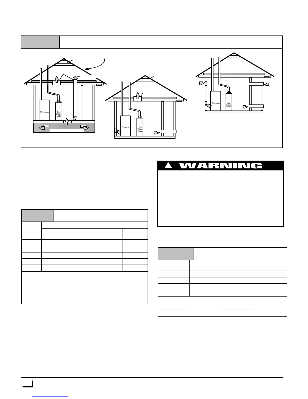
2. Figure 5 illustrate how to provide combustion and ventila-
BTU
H
tion air. A minimum of two permanent openings, one inlet
and one outlet, are required.
3. Oneopening MUSTbewithin12² of thefloorandthesecond
opening within 12 ² of the ceiling.
Figure 5
Outside Air (This is ONLY a guide. Subject to codes of country having jurisdiction.)
This installation NOT approved in Canada
Gable Vent
Gas Vent
VentilatedAttic
TopAbove Insulation
Outlet Air (1)
VentilatedCrawl Space
alternate Inlet Air (1)
alternate Inlet Air (1)
Soffit Vent
Inlet
Air (1)
Gas Vent
VentilatedAttic
TopAbove Insulation
OutletAir (1)
4. Size openings and ducts per Table 1.
5. Horizontal duct openings require 1 square inch of free area
per 2,000 BTUH of combined input for all gas appliances in
area (see Table 1).
6. Vertical duct openings or openings directly to outside require 1 square inch of free area per 4,000 BTUH for combined input of all gas appliances in area (see Table 1).
Table 1 Free Area
BTUH
Input
Rating
50,000 25 sq. in. 12.5 sq. in. 4²
75,000 37.5 sq. in. 18.75 sq. in. 5²
100,000 50 sq. in. 25 sq. in. 6²
125,000 62.5 sq. in. 31.25 sq. in. 7²
150,000 75 sq. in. 37.5 sq. in. 7²
Minimum FreeAreaRequiredfor Each Opening
HorizontalDuct
(2,000 BTUH)
VerticalDuct or openings
to outside(4,000BTUH)
Round Duct
(4,000 BTUH)
EXAMPLE: Determining Free Area
Appliance 1 Appliance 2 Total Input
100,000 + 30,000 = (130,000 ¸ 4,000) = 32.5 Sq. In. Vertical
Appliance 1 Appliance 2 Total Input
100,000 + 30,000 = (130,000 ¸ 2,000) = 65 Sq. In. Horizontal
One permanent opening, commencing within 12² of the top of the
enclosure,shall bepermittedwheretheequipmenthasclearances
of at least 1² from the sides and back and 6² from the front of the
appliance. The opening shall directly communicate with the outdoorsorshallcommunicatethrough a vertical orhorizontalductto
theoutdoors orspaces(crawlorattic)thatfreelycommunicatewith
the outdoors, and shall have a minimum free area of:
· 1 sq. in per 3000 Btu per hr. of the total input rating of all
equipment located in the enclosure, and
· Not less than the sum of the areasofallventconnectorsin
the confined space.
8
Gas Vent
Gable Vent
Soffit Vent
Inlet
Air (2)
Outlet
Air (1)
Inlet
Air (1)
Minimum OneInlet and One OutletAirSupply is Required
May bein any Combination Shown
Inlet Air OpeningMust be Within12² of floor
Outlet AirOpeningMust be Within12² of ceiling
(1) 1 Square Inchper 4000 BTUH
(2) 1 Square Inchper 2000 BTUH
Inlet
Air (2)
Outlet
Air (2)
Unconfined Space Installation
!
CARBON MONOXIDE POISONING HAZARD
Failure to supply additional air by means of ventilation
grilles or ducts could result in death and/or personal
injury.
An unconfined space or homes with tight construction
may not have adequate air infiltration for proper
combustion and ventilation of flue gases.
Most homes will require additional air.
Anunconfinedspaceisdefinedasanareahavingaminimumvolumeof50c ubic feet per 1,000 Btuhtotalinputratingforallgasappliances in area. Refer to Table 2 for minimum area required.
Table 2
BTUH Input
Rating
50,000 312
78,000 490
114,000 712
155,000 968
EXAMPLE: NOTE: Square feet is based on 8 foot ceilings.
28,000 BTUH
1,000 8¢ Ceiling Height
NOTE: Refer to definitions in section titled Unusually Tight
Construction. If any one of the conditions apply,the space MUST
be considered confined space regardless of size.
1. Adjoining rooms can be considered part of an unconfined
area if there are openings without doors between rooms.
2. An attic or crawl space may be considered an unconfined
space provided there are adequate ventilation openings directly to outdoors. Openings MUST remain open and NOT
haveanymeansofbeing closed off.Ventilationopenings to
outdoorsMUST be at least 1² square of free area per 4,000
BTUH of total input rating for all gas appliances in area.
Unconfined Space
Minimum Area in Square Feet
Minimum Area in Square Feet
X 50CubicFt. = 1,400 = 175 Sq. Ft.
440 01 1020 02
3. Install air intake a minimum of 12² above maximum snow
level and clear of any obstruction. Duct or ventilation openingrequiresonesquareinch of freeareaper4,000BTUH of
total input rating for all gas appliances in area.
1
4. Air inlet MUST be screened with not less than
screen.
/4² mesh
Unusually Tight Construction
In unconfined spaces, infiltration may be adequate to provide air
for combustion, ventilation and dilution of flue gases. However, in
buildingswithunusuallytightconstruction, additional air MUSTbe
provided using the methods described in section titled Confined
Space Installation:
Unusually tight construction is defined as: Construction with
1. Walls and ceilings exposed to the outside have a continuous,sealedvaporbarrier. Openings aregasketedorsealed
and
2. Doors and openable windows are weather stripped and
3. Otheropenings are caulked or sealed. These include joints
around window and door frames, between sole plates and
floors, between wall--ceiling joints, between wall panels, at
penetrations for plumbing, electrical and gas lines, etc.
VentilationAir
Someprovincial codes and local municipalities require ventilation
or make--up air be brought into the conditioned space as replacementair.Whichevermethodis used,themixedreturnair temperature across the heat exchanger MUST not fall below 60°Forflue
gaseswill condenseintheheatexchanger.Thiswillshortenthelife
of the heat exchanger and possibly void your warranty.
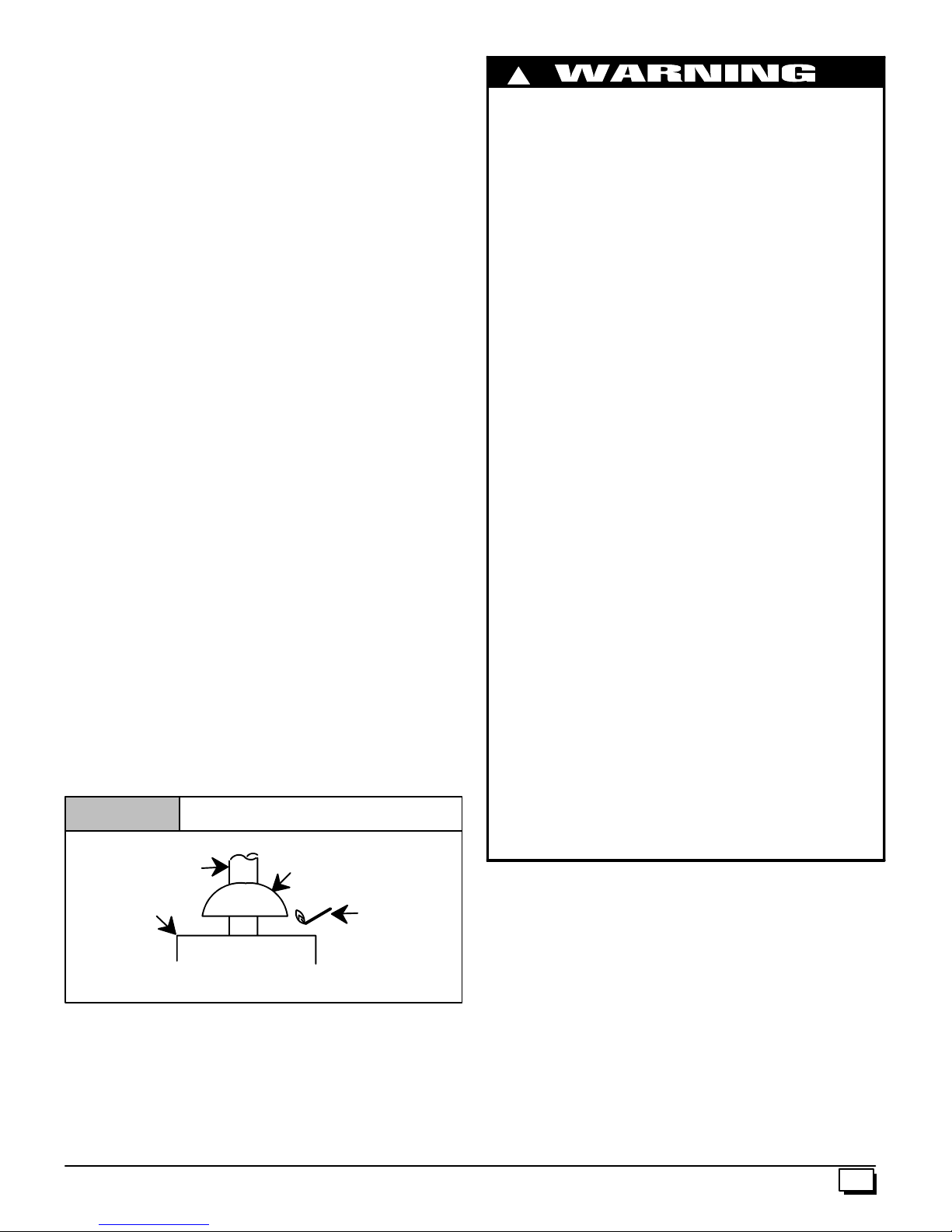
Venting and Combustion Air Check
NOTE: When an existing Category I furnace is removed or re placed,theoriginalventingsystemmaynolongerbesizedtoproperly vent the attached appliances, and to make sure there is
adequatecombustionairforallappliances,MAKETHEFOLLOW-
ING CHECK.
Figure 6
Typical Gas
Water Heater
Ifflamepullstowardsdraft hood, thisindicatessufficient
venting.
Vent Check
Draft HoodVent Pipe
Match
!
CARBON MONOXIDE POISONING HAZARD
Failure to follow the steps outlined below for each
applianceconnectedto theventingsystem beingplaced
into operation, while all other appliances connected to
the venting system are not in operation could result in
carbon monoxide poisoning or death.
Thefollowingstepsshallbe followed for each appliance
connected to the venting system being placed into
operation, while all other appliances connected to the
venting system are not in operation:
1. Seal any unused openings in the venting system.
2. Inspecttheventing systemfor propersize and horizontal
pitch, as required in the National Fuel Gas Code, ANSI
Z223.1/NFPA 54 or CSA B149.1, Natural Gas and Pro pane Installation Codes and these instructions. Deter-
minethatthereis no blockage or restriction,leakage,corrosion and other deficiencies which could cause an un safe condition.
3. As far as practical, close all building doors and windows
andalldoorsbetweenthespaceinwhichtheappliance(s)
connected to the venting system are located and other
spaces of the building.
4. Close fireplace dampers.
5. Turnonclothes dryers and any appliance not connected
to the venting system. Turnon any exhaust fans, such as
range hoods and bathroom exhausts, so they will operatingatmaximumspeed.Donotoperatea summerexhaust
fan.
6. Followthelightinginstructions.Placethe appliancebeing
inspected into operation. Adjust thermostat so appliance
is operating continuously.
7. Test for spillage from draft hood equipped appliances at
thedrafthoodreliefopeningafter5minutesofmainburner
operation.Usetheflameofamatchorcandle.(Figure 6)
8. If improper venting is observed, during any of the above
tests, the venting system must be corrected in accordance with the National Fuel Gas Code, ANSI
Z223.1/NFPA 54 and/or CSA B149.1, Natural Gas and
Propane Installation Codes.
9. After it has been determined that each appliance connected to the venting system properly vents when tested
as outlined above, return doors, windows, exhaust fans,
fireplace dampers and any other gas-- fired burning appliance to their previous conditions of use.
For Two Pipe Installation
Thisfurnace canNOTbecommonventedorconnectedtoanytype
B, BW or L vent or vent connector,norto any portion of a factory-built or masonry chimney. If this furnace is replacing a previously
common-ventedfurnace,itmaybenecessarytoresizetheexisting
vent and chimney to prevent oversizing problems for the other remainingappliance(s).See“VentingandCombustionAirCheck” in
this section. ThisfurnaceMUSTbeventedtotheoutside.
440 01 1020 02
9
4. Vent and Combustion Air Piping
!
CARBON MONOXIDE POISONING, FIRE AND EXPLOSION
HAZARD
Failure to properly vent this furnace can result in death,
personal injury and/or property damage.
Read and follow all instructions in this section.
SinglePipe(N9MP1Models)
This furnace is certified as a category IV appliance. This furnace
requires ventilation openings to provide air for proper combustion
and ventilation of flue gases. All duct or openings for supplying
combustion and ventilation air must comply with the gas codes or
in absence of local codes, the applicable national codes.
Whentheinstallation iscomplete,see the“Ventingand Combus-
tion Air Check” in this manual.
Direct Vent (N9MP2 Models)
This furnace is certified as a category IV appliance. This furnace
uses outside air for combustion ONLY, it MUST be taken from the
sameatmosphericpressure zoneastheventpipe. See Confined
SpaceInstallationintheCombustionand VentilationAir inthis
manual.
Dual Certified (*9MPD Models)
This furnace is certified as a category IV appliance. This furnace
can be installed as a direct vent furnaceusingoutsideair forcombustionorthefurnacecanuseairfrominsidethestructure forcombustion. The INLET air pipe is optional. If combustion air comes
frominsidethestructure,adequatemakeupair MUSTbeprovided
tocompensateforoxygen burned. See ConfinedSpaceInstalla-
tion in the Combustion and Ventilation Air chapter.If combustion air is drawn from outside the structure,it MUST be taken from
the same atmospheric pressure zone as the vent pipe.
Contaminated Combustion Air
Installationsincertain areasortypesof structureswillincrease the
exposure to chemicals or halogens that may harm the furnace.
Thefollowingareasortypesofstructuresmaycontainor have exposure to the substances listed below. The installation must be
evaluatedcarefullyasitmaybenecessarytoprovideoutsideairfor
combustion.
· Commercial buildings.
· Buildings with indoor pools.
· Furnaces installed in laundry rooms.
· Furnaces installed in hobby or craft rooms.
· Furnaces installed near chemical storage areas.
· Permanent wave solutions for hair.
· Chlorinated waxes and cleaners.
· Chlorine based swimming pool chemicals.
· Water softening chemicals.
· De--icing salts or chemicals.
· Carbon tetrachloride.
· Halogen type refrigerants.
· Cleaning solvents (such as perchloroethylene).
· Printing inks, paint removers, varnishes, etc.
· Hydrochloric acid.
10
· Sulfuric Acid.
· Solvent cements and glues.
Antistatic fabric softeners for clothes dryers.
·
· Masonry acid washing materials.
Vent and Combustion Air Piping Guidelines
ThisfurnaceisapprovedforventingwithSchedule40PVC,CPVC,
ABS, Cellular Core pipe fittings and SDR--26 PVC.
NOTE: All PVC, CPVC, ABS, and Cellular Core pipe fittings, solventcement,primers and procedures MUST conformtoAmerican
National Standard Institute and American Society for Testing and
Materials (ANSI/ASTM) standards.
· PipeandFittings -- ASTM D1785, D2241, D2466, D2661,
D2665, F--891, F--628
· PVC Primer and Solvent Cement -- ASTM D2564
· Procedure for Cementing Joints -- Ref ASTM D2855
NOTE: All vent piping MUST be installed in compliance with local
codesorordinances, theseinstructions,goodtradepractices,and
codes of country having jurisdiction.
1. Determinethebestroutingand termination fortheventpipe
and air inlet pipe by referring to all of the instructions and
guidelines in this Section.
2. Determine the size required for the vent pipe and air inlet
pipe.
3. Loosely assemble all venting parts without adhesive (pipe
joint cement) for correct fit before final assembly.
4. Use of vertical piping is preferred because there will be
some moisture in the flue gases that may condense as it
leavestheventpipe(See Special Instruction ForHorizontal
Vents).
5. Theverticalventpipe MUST besupportedsothatno weight
is allowed to rest on the combustion blower.
6. Exhaust vent piping or air inlet piping diameter MUST NOT
be reduced.
7. All exhaust vent piping from the furnace to termination
MUST slope upwards. A minimum of
required to properly return condensate to the furnace drain
system.
8. Use DWV type long radius elbows whenever possible, as
they provide for the minimum slope on horizontal runs and
they provide less resistance in the vent system. If DWV elbows cannot be used, use two, 45° elbows when possible.
On horizontal runs the elbows can be slightly misaligned to
provide the correct slope.
9. All horizontal pipe runs MUST be supported at least every
fivefeetwithgalvanizedstraporotherrustresistantmaterial. NO sags or dips are permitted.
10. All vertical pipe runs MUST be supported every six feet
where accessible.
11. The minimum pipe run length is 2¢.
12. The piping can beruninthesamechase or adjacent tosupply or vent pipe for water supply or waste plumbing. It can
also be run in the same chase with a vent from another 90+
furnace.
NOTE:InNO case can the piping be run in a chase where
temperatures can exceed 140° F. or where radiated heat
from adjacent surfaces would exceed 140° F.
13. The vent outlet MUST be installed to terminate in the same
atmospheric pressure zone as the combustion air inlet.
14. Theventsystemcanbeinstalledinanexistingunusedchimney provided that:
1
/4² per foot of run is
440 01 1020 02
· Both the exhaust vent and air intake run the length of the
chimney.
· No other gas fired appliance or fireplace (solid fuel) is
vented into the chimney.
· The top of the chimney MUST be sealed flush or crowned
uptosealagainstrainormeltingsnow so ONLYthepiping
protrudes.
· The termination clearances shown in Figure 7 are main-
tained.
15. Furnaceapplicationswithverticalventsrequiringventdiameter increaser fittings must have increaser fittings installed
in vertical portion of the vent. Condensate will be trapped in
the vent if the vent diameter is increased prior to having an
elbowturnedupward.This could cause nuisancetrippingof
the pressure switch.
Piping Insulation Guidelines
NOTE:Useclosedcell,neopreneinsulation orequivalent.If Fiberglass or equivalent insulation is used it must have a vaporbarrier.
UseRvalues of 7upto10¢,R--11if exposureexceeds10¢.IfFiberglassi nsulation isused,exteriortothestructure,thepipeMUSTbe
boxed in and sealed against moisture.
1. When the vent or combustion air pipe height above theroof
exceeds 30², or if an exterior vertical riser is used on a horizontal vent to get above snow levels, the exterior portion
MUST be insulated.
2. When combustion air inlet piping is installed above a suspended ceiling, the pipe MUST be insulated with moisture
resistant insulation such as Armaflex or other equivalent
type of insulation.
3. Insulatecombustionairinletpipingwhenruninwarm,humid
spaces such as basements.
Sizing Combustion Air and Vent Pipe
Consult Table 3 or Table 4 to s elect the proper diameter exhaust
and combustion air piping. Exhaust and combustion air piping is
sized for each furnace Btuh size based on total lineal vent length
(on inlet or outlet side), and number of 90° elbows required. Two
45° elbows can be substituted for one 90° elbow. The elbow or elbowsusedforventterminationoutsidethestructureAREcounted,
including elbows needed to bring termination above expected
snow levels. The elbow inside the furnace on the *9MPD IS NOT
included in the count.
Table 3
50,000, 75,000 & 80,000 Btuh Furnaces
40¢ & (5) 90° elbows with 2² PVC pipe or
70¢ & (5) 90° elbows with 3² PVC pipe
40¢ & (5) 90° elbows with 3² PVC pipe or
70¢ & (5) 90° elbows with 3² PVC pipe &
Long Vent Kit (See Tech. Manual)
40¢ & (5) 90° elbows with 3² PVC pipe
Elbows are DWV Long Radius Type for 2² and 3² vents.
If more than five elbows are required, reduce the length of
both the inlet and exhaust pipes 5¢ for each additional elbow
used.
Pipe Diameter Table
N9MP1 & *9MPD Models
100,000 Btuh Furnace
125,000 Btuh Furnace
NOTE: It is allowable to use larger diameter pipe and fitting than
shown in the tables but not smaller diameters than shown.
Table 4
50,000 & 80,000 Btuh Furnaces
40¢ & (5) 90° elbows with 2² PVC pipe or
70¢ & (5) 90° elbows with 3² PVC pipe
25¢ & (3) 90° elbows with 2² PVC pipe or
40¢ & (5) 90° elbows with 2² PVC pipe &
Long Vent Kit (See Tech. Manual) or
70¢ & (5) 90° elbows with 3² PVC pipe
40¢ & (5) 90° elbows with 3² PVC pipe or
70¢ & (5) 90° elbows with 3² PVC pipe &
Long Vent Kit (See Tech. Manual)
40¢ & (5) 90° elbows with 3² PVC pipe
Elbows are DWV Long Radius Type for 2² and 3² vents.
If more than five elbows are required, reduce the length of
both the inlet and exhaust pipes 5¢ for each additional elbow
used.
Pipe Diameter Table
N9MP2 Models
75,000 Btuh Furnaces
100,000 Btuh Furnace
125,000 Btuh Furnace
For “Concentric Termination Kit” Venting table, see
“Section 11” in this manual.
VentTerminationClearances
!
CARBON MONOXIDE POISONING, FIRE AND EXPLOSION
HAZARD
Failure to properly vent this furnace can result in death,
personal injury and/or property damage.
Inlet and outlet pipes may NOT be vented directly above
each other.
1. Determine termination locations based on clearances specified in following steps and as shown in Figure 7,
Figure 19, through Figure 27.
For “Concentric Termination Kit” clearances, see Figure 45,
Figure 46, Figure 47, Figure 48 and Figure 49 in “Section 10”
in this manual.
2. The vent termination must be located at least 12² above
ground or normally expected snow accumulation levels.
3. DoNOTterminateoverpublicwalkways.Avoidareaswhere
condensate may cause problems such as above planters,
patios,oradjacent towindowswheresteam maycausefogging.
4. The vent terminationshallbelocatedatleast4¢ horizontally
from any electric meter, gas meter,regulator,andanyrelief
equipment. These distances apply ONLY to U.S. installations.
5. The vent termination is to be located at least 3¢ above any
forced air inlet located within 10¢ ; and at least 10¢ from a
combustionairintake of another appliance, exceptanother
direct vent furnace intake.
6. InCanada,theCanadianFuel Gas Code takesprecedence
over the preceding termination instructions.
440 01 1020 02
11
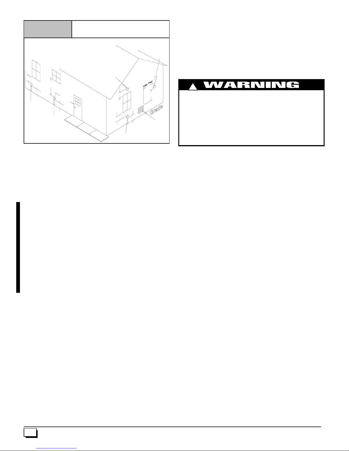
Figure 7
Vent Termination Clearances
(United States Only)
In Canada See Canadian Fuel Gas Code
Other Than
Direct Vent
Terminal
9²
Direct Vent
Terminal
50,000 Btuh
or less
12²
²
²²
Other Than
Direct Vent
Terminal
4¢
¢
¢¢
12²
²
²²
12²
²
²²
Direct VentTerminal
More Than 50,000 Btuh
12²
4¢
¢
¢¢
²
²²
12²
5
/8² may also be used, as allowed by local codes. Alternate drain
pipes and hoses may be used as allowed by local codes.
1
/4² perfootdownwardslopetoward
1
/4² per foot slope to the conden-
Other Than
Direct Vent
Terminal
Thedrainlinemustmaintain a
thedrain.
1
/4² perfootisrecommended.Installation of an overflow
line is recommended when the
sate drain cannot be maintained. See Figure 1 for proper routing
and installation of the overflow.
DONOTtrapthedrainline inanyotherlocationthanatthecondensate drain trap supplied with the furnace.
10¢
¢
¢¢
3¢
¢
¢¢
!
FROZEN AND BURST WATER PIPE HAZARD
Failure to do so may result in burst water pipes, serious
property damage and/or personal injury.
If a condensate pump is installed, a plugged condensate
Forced Air
²
²²
Inlet
10 -- 11 --3 6
drainorafailedpump maycausethe furnacetoshutdown.
Donotleavethehomeunattendedduringfreezing weather
without turning off water supply and draining water pipes
or otherwise protecting against the risk of frozen pipes.
CondensateDrain Trap
Thisfurnaceremovesbothsensible and latent heatfromtheproducts of combustion. Removal of the latent heat results in condensationofthe watervapor.The condensateisremovedfromthe
furnace through the drains in the plastic transition and the vent fitting. The drains connect to the externally mounted condensate
drain trap on the left or right side of the furnace.
The startup of a new furnace will involve a cycle or two of the furnace to properly prime the condensate trap with water. Until the
trap is fully primed, some condensate will be pulled into the combustionblower. Thefurnacemaycycleonthepressureswitch connected to the plastic transition box due to condensate buildup.
Afterthetrapisprimed,thecondensatewillstartdrainingfromthe
furnace. The combustion blower will clear out any remaining condensateintheblowerhousing through theventfittingdownstream
oftheblower.Notethatthe condensate trap can alsobeprimedby
pouring water into the1/2² drain hose. Remove the1/2² ID drain
hosefromeitherthe gutter orthewhitePVCTeeTrap.Usingafunnelpoureight(8)ounces of waterinto1/2² IDdrainhose.Waterwill
flow through the drain hose and into the condensate drain trap.
Thiswillprimeboththe ventandthe transitionsidesofthetrap.Reconnectthe1/2² IDdrain hosetotheoriginalcomponent, eitherthe
gutter or the PVC Tee Trap.
The condensate drain trap supplied with the furnace MUST be
used. The drain connection on the condensate drain trap is sized
3
for
/4² PVCorCPVCpipe,however alternate1/2² CPVC(nominal
5
/8² O.D.) or vinyl tubing with a minimum inner diameter (I.D.) of
If possible DO NOT route the drain line where it may freeze. The
drain line must terminate at an inside drain to prevent freezing of
the condensate and possible property damage.
1. AcondensatesumppumpMUSTbeusedifrequiredbylocal
codes, or if no indoor floor drain is available. The condensate pump must be approved for use with acidic condensate.
2. A plugged condensate drain line or a failed condensate
pumpwillallow condensatetospill.Ifthefurnaceis installed
where a condensate spill could cause damage, it is recommended that an auxiliary safety switch be installed to preventoperationoftheequipmentinthe event of pump failure
or plugged drain line. If used, an auxiliary safety switch
should be installed in the R circuit (low voltage) ONLY.
3. If the auxiliary switch in the condensate pump is used, the
furnacemayshutdowndue to a blocked condensate line or
failed pump. To prevent frozen water pipes see the “Frozen
Water Pipe Hazard” section on Page 4 of this manual.
Condensate Drain TrapFreeze Protection
SpecialprecautionsMUSTbemadeif installing furnaceinanarea
which may drop below freezing. This can cause improper operation or damage to the equipment. If the the furnace environment
has the potential of freezing, the drain trap and drain line must be
protected.Use3to 6 wattperfootat 115v olt, 40° Fself--regulating
shielded and waterproof heat tape. Wrap the drain trap and drain
linewiththeheattapeandsecurewiththeties.Followtheheattape
manufacturer’s recommendations.
12
440 01 1020 02
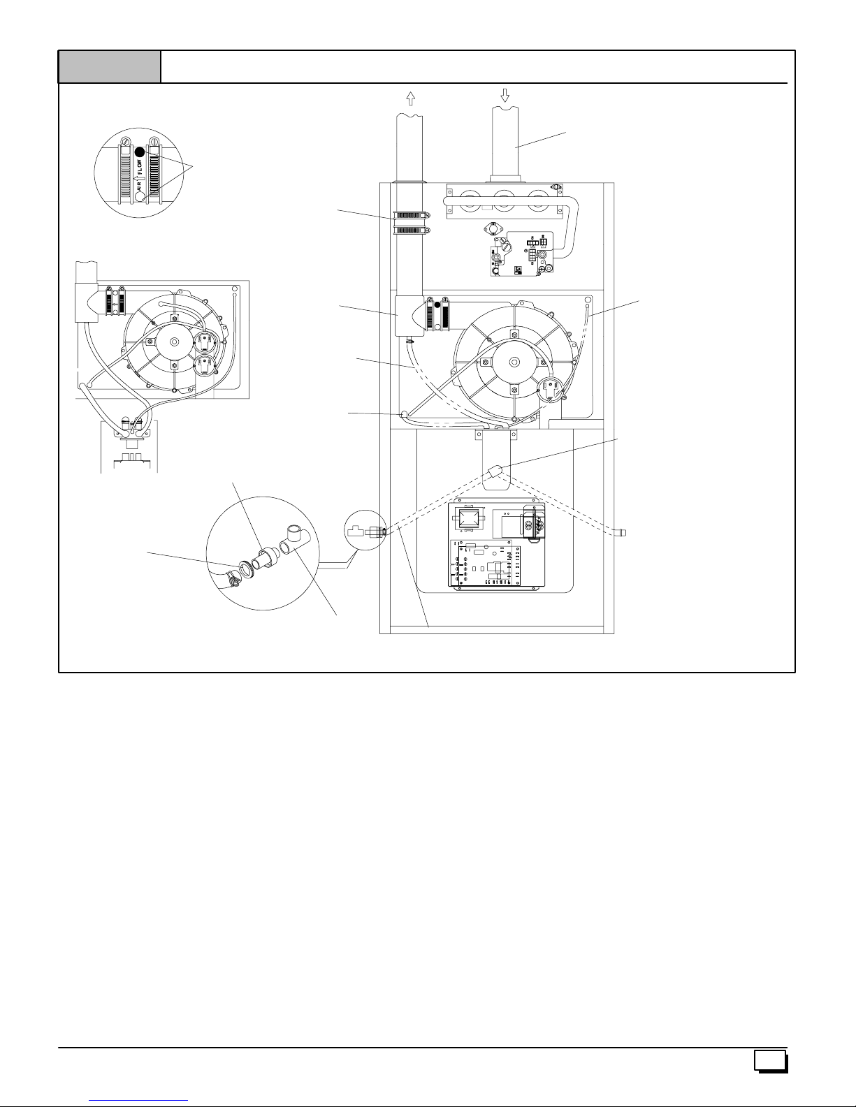
Figure 8
Upflow Installations Top Vent
Vent Drain
&Clamps
Dual Pressure Switch Detail
FLOW
AIR
Casing Grommet
Black Rubber
5
/
²
² ID
²²
8
(Loose partsbag)
Yellowor black Plastic
Caps (2)
Coupling & Clamps
(Optional)
DrainTee
1
/
²
² ID Drain
²²
2
Hose & Clamps
5
/
²
² ID Hose & Clamps
²²
8
Drain ConnectorBlackPVC
3
/
²
² PVC X1/
²²
4
(Loose partsbag)
²
² CPVC
²²
2
EXHAUST
Single Pressure Switch
INLET
On Some Models
ONLY
StreetElbow
1
/
2
(Loose partsbag)
3
/
²
² ID Rubber Tube
²²
16
²
² CPVC
²²
3
/
²
Drain LineVent Tee
1
/
²
² CPVC (Field supplied)
²²
2
² PVC or
²²
4
Upflow Installations Top Vent (See Figure 8)
Removeplug fromtheside ofthefurnacecasingwhereDrainTube
will exit.
5
Install casing grommet (black rubber
parts bag)
1
Install the
/2² CPVC street elbow on discharge of Trap
Install the black PVC tube connector (
loose parts bag) as shown in the illustration above.
5
Cut the black Drain Tube(
/8² ID -- in loose parts bag) to length to
fit between Trap and tube connector through grommet.
Clamp both ends of the Drain Tube using clamps provided.
/8² ID grommet -- in loose
3
/4² PVC x1/2² CPVC from
Drain Tube(& Clamps) Black Rubber5/
Cut lengthtofit(Loose parts bag)
8
²
² ID,
²²
25--24--42
GluetheCPVCstreetelbowtotheTrapusing appropriate cleaner
and solvent cement.
Connect the Tee trap and the main drain line exiting the casing as
shown Figure 17.
Note: It is recommended that all PVC piping and fitting connectionsbefitupand inspected before finalcementing.Trap must be
primed before operation. Verify all condensate drain connections are securely clamped. A coupling and clamps (in loose part
bag)maybe installedasshownfor futureservicingofthevent system.
440 01 1020 02
13
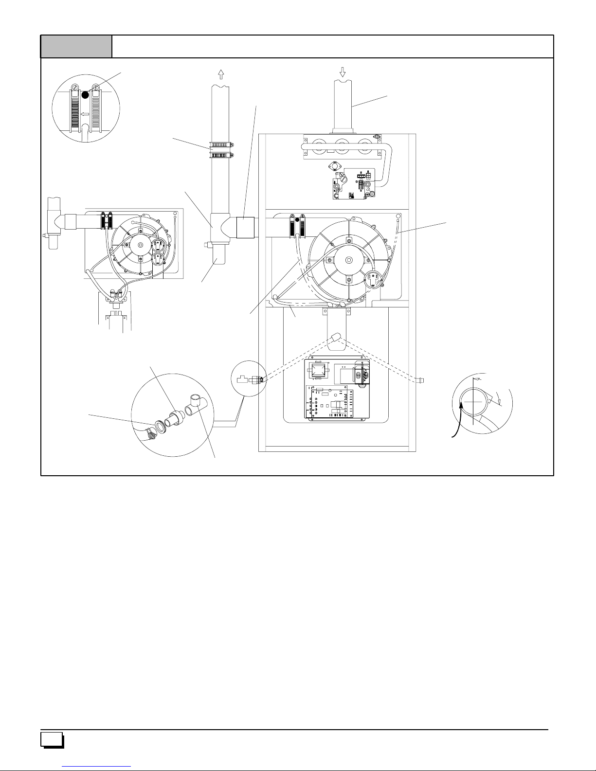
Figure 9
Upflow Installations Vent thru Left Side
Yellowor black Plastic
Cap
2²²²² PVC Coupling
INLET
On Some Models
ONLY
Vent Drain
&Clamps
Dual Pressure Switch Detail
AIR FLOWAIR FLOW
Drain ConnectorBlackPVC
3
/
²
² PVC X1/
²²
4
(Loose partsbag)
Casing Grommet
Black Rubber
5
/
²
² ID
²²
8
(Loose partsbag)
Coupling & Clamps
(Optional)
Either:ThePVC
Drain Teeor a field
supplied 2²²²² PVC Tee
²
² CPVC
²²
2
EXHAUST
TeeTrap White PVC
(loose partsbag)
1
/
²
² ID Drain Tube
²²
2
Black (Move from
bottom of drain tee
if installed)
Single Pressure Switch
5
/
²
² ID Hose
²²
8
&Clamps
3
/
²
² ID Rubber Tube
²²
16
SIDE VIEW
Rotate downward
5°°°° to 10°
NOTE: Built--in channel will
be angled5° to 10° also.
°
°°
Drain LineVentTee
² PVC or1/
²²
4
²
² CPVC (Fieldsupplied)
²²
2
3
/
²
Upflow Installations Vent thru Left Side (See Figure 9)
RemoveDrainTeefrominducerdischargeandremoveblackDrain
Tube (1/2² ID) from bottom of Drain Tee.(*9MPD models only)
Install Vent Pipe grommet in side of casing.
Cut an appropriate length of 2² PVC pipe long enough to exit the
cabinet and connect the vent drain to either:
· A standard field supplied 2² PVC tee (N9MP1 and 2 models),
or
· A2² PVC coupling fastened onto the Drain Tee(*9MPDmod-
els)
Install Tee trap into bottom of tee.
Install the
Install the black PVC drain connector (
1
/2² CPVC street elbow on discharge of Trap
3
/4² PVC x1/2² CPVC from
loose parts bag) as shown in the illustration above.
Cut the black Drain Tube(
fit between Trap and tube connector through grommet.
Clamp both ends of the Drain Tube using clamps provided.
GluetheCPVCstreetelbowtotheTrapusing appropriate cleaner
and solvent cement.
Connect the Tee trap and the main drain line exiting the casing as
shown in Figure 1 7.
Note: It is recommended that all PVC piping and fitting connec-
tions be fit up and inspected before final cementing. Both the in-
ternal Trap and the external Tee Trap must be primed before
operation. Verify all condensate drain connections are securely
clamped. A coupling and clamps (in loose part bag) may be
installed as shown for future servicing of the vent system.
14
25--24--43
5
/8² ID -- in loose parts bag) to length to
440 01 1020 02
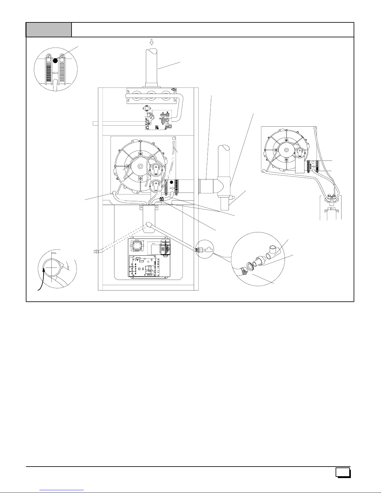
Figure 10
All Models Vent thru Right Side
Yellowor black Plastic
Cap
INLET
On Some Models
ONLY
Vent Drain
&Clamps
5
/
8
&Clamps
SIDE VIEW
Rotate downward
5°°°° to 10°
²
² ID Hose
²²
°
°°
Dual Pressure Switch
AIR FLOW
3
/
²
² ID
²²
16
Rubber
Tube
2²²²² PVC Coupling
Barbed Coupling,1/
(loose partsbag)
Either:ThePVC
Drain Teeor a field
supplied 2²²²² PVC Tee
Single Pressure Switch Detain
TeeTrap White PVC
(loose partsbag)
Elbows Tubes(2) & Clamps Black,
1
/
²
² ID (loose partsbag)
²²
2
²
² OD
²²
2
Drain LineVentTee
1
/
or
2
Drain ConnectorBlackPVC
3
/
4
(Loose partsbag)
3
/
²
² PVC
²²
²
² CPVC
²²
2
4
²
² CPVC (Field supplied)
²²
²
² PVC X1/
²²
NOTE: Built--in channel will
be angled5° to 10° also.
All Models Vent thru Right Side (See Figure 10)
Disconnect the black Drain Tube between the drain vent and the
Trap.
Rotate the inducer 180° for a right side vent after loosening the 4
inducer attachment screws. Reinstall and retighten the inducer
screws to 20² pounds torque.
1
Using the
togetherwiththe2 short
dischargeportoftheventdraintotheTrap. Secureallconnections
with clamps.
Install the vent pipe grommet into the casing
Cut an appropriate length of 2² PVC pipe long enough to exit the
cabinet and connect the vent drain to either:
· A standard field supplied 2² PVC tee (N9MP1 and 2 mod-
· A2² PVC coupling fastened onto the Drain Tee (*9MPD
Install Tee Trap into bottom section of Tee.
Removeplug fromtheside ofthefurnacecasingwhereDrainTube
will exit.
/2² OD barbed coupling in the loose parts bag connect
1
/2² IDelbowtubes andconnectthelower
els), or
models)
Casing Grommet
Black Rubber
(Loose partsbag)
Install casing grommet (black rubber
5
/
²
² CPVC
²²
8
5
/8² ID grommet -- in loose
25--24--44
parts bag)
Install the
Install the black PVC tube connector (
1
/2² CPVC street elbow on discharge of Trap
3
/4² PVC x1/2² CPVC from
loose parts bag) as shown in the illustration above
5
Cut the black Drain Tube(
/8² ID -- in loose parts bag) to length to
fit between Trap and tube connector through grommet.
Clamp both ends of the Drain Tube using clamps provided.
GluetheCPVCstreetelbowtotheTrapusing appropriate cleaner
and solvent cement.
Connect the Tee trap and the main drain line exiting the casing as
shown in Figure 1 7.
Note: It is recommended that all PVC piping and fitting connec-
tions be fit up and inspected before final cementing. Both the in-
ternal Trap and the external Tee Trap must be primed before
operation. Verify all condensate drain connections are securely
clamped. A coupling and clamps (in loose part bag) may be
installed as shown for future servicing of the vent system.
440 01 1020 02
15
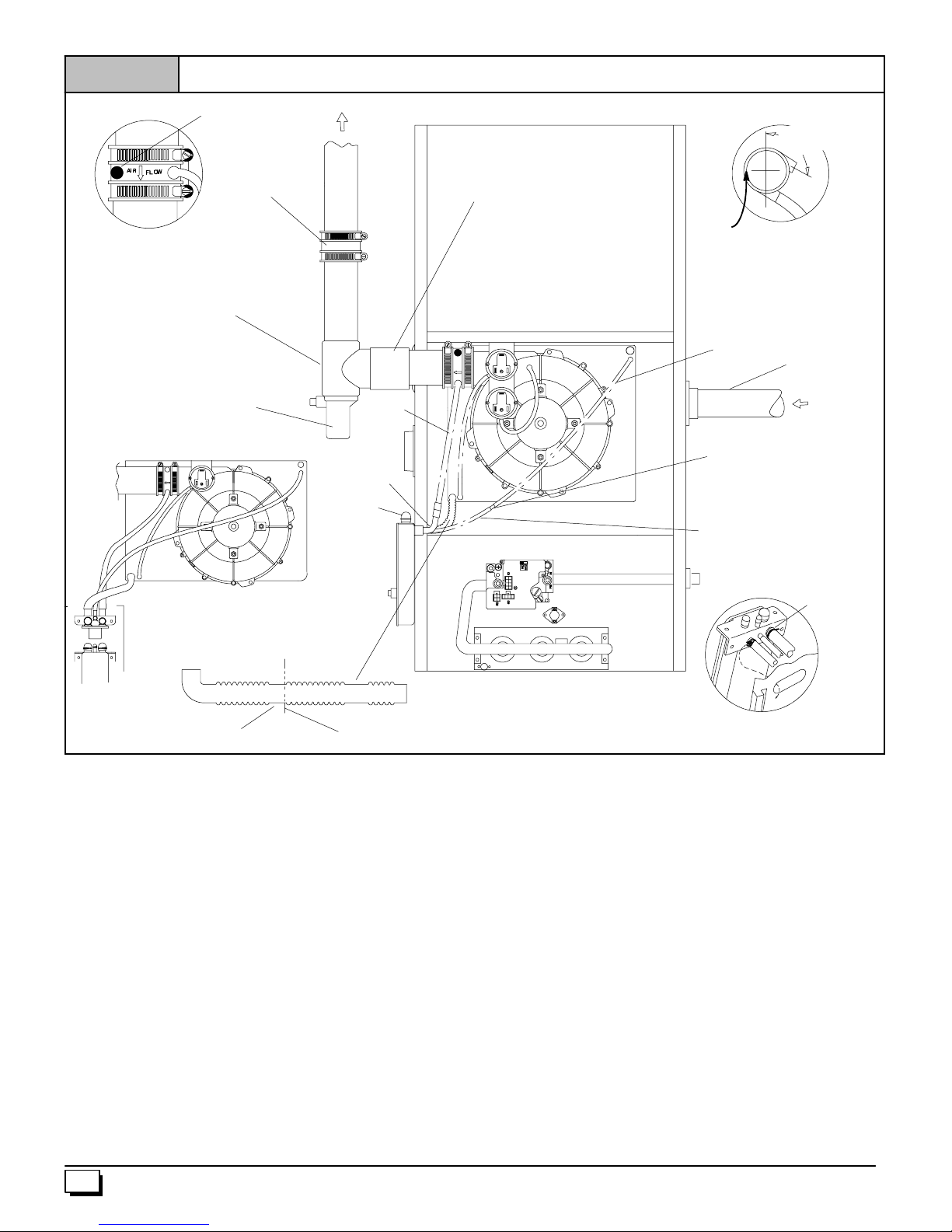
Figure 11
Downflow Left Side Vent and Trap
Yellowor black Plastic
Cap
Coupling & Clamps
(Optional)
Vent Drain
&Clamps
Either:ThePVC
Drain Teeor a field
supplied 2²²²² PVC Tee
TeeTrap White PVC
(loose partsbag)
Single Pressure Switch Detail
FLOW
AIR
EXHAUST
Drain
Elbow (1)
WARNING
Move Caps
to top of
trap
1
/
²
² ID
²²
2
Drain
Hose
2²²²² PVC Coupling
Dual Pressure Switch
FLOW
AIR
SIDE VIEW
Rotate downward
5°°°° to 10°
NOTE: Built--in channel will
be angled5° to 10° also.
3
/
²
² ID
²²
16
Rubber Tube
On Some Models
ONLY
INLET
FlexibleTubing Connector,
3
/
²
² OD (loose partsbag)
²²
16
ReliefTube,
Extension Black,
3
/
²
² ID Cut to fit
²²
16
(loose partsbag)
°
°°
5
/
²
Drain TubeBlack,
Cut at straightsection
Leave room forclamp
² ID Corrugated
²²
8
Cut Here
Downflow Left Side Vent and Trap (See Figure 11)
Removetheinducermountingscrews,rotatetheinducer180° and
retighten the inducer screws to 20² pounds torque.
Disconnect the hoses from the Trap assembly, and remove Trap
and Trap mounting bracket from the blower compartment. Using
cover plate and gasket provided in the loose parts bag, cover the
holefromtheburner compartment to the blowercompartmentand
secure with screws.
Movethecapstothe top of theTrapandmount the Trapexternally
to the left side of the unit using the 2 screws provided.
5
Cutthe
bend end to the Trap and fasten the straight end to the transition
drain. Secure both connections with clamps.
Reconnect the
andsecurewithaclamp.. In somecases, additional length will be
required for this hose. Use the Black plastic
plinganda suitablesectionof1/2² IDhose tomakethe connection.
Secure all connections with clamps
Connect the
thetop portofthetransitionasshowninthepicture. Insomecases,
/8² IDcorrugatedhoseasshownaboveandfastenthe90°
1
/2² ID drain hose from the vent drain to the Trap
1
/2² OD barbed cou-
3
/16² ID relief tube from the small port on the Trap to
Trap Connection
Preassemble&
insertinto furnace
additional hose length will be needed. Use the clear plastic
“Clamp ears”
PointedOUT
25--24--45
3
/
16
ODflexibletubingconnectorandasuitablelengthofextra3/16² ID
hose to make this connection.
Install the vent pipe grommet into the casing
Cut an appropriate length of 2² PVC pipe long , enough to exitthe
cabinet and connect the vent drain to either:
· A standard field supplied 2² PVC tee (N9MP1 and 2 models), or
· A2² PVC coupling fastened onto the Drain Tee (*9MPD
models)
Install Tee Trap into bottom section of Tee.
Connect the Tee trap and the main drain line exiting the casing as
shown in Figure 1 7.
Note: It is recommended that all PVC piping and fitting connec-
tions be fit up and inspected before final cementing. Both the ex-
ternal Trap and the external Tee Trap must be primed before
operation. Verify all condensate drain connections are securely
clamped. A coupling and clamps (in loose part bag) may be
installed as shown for future servicing of the vent system.
²
16
440 01 1020 02
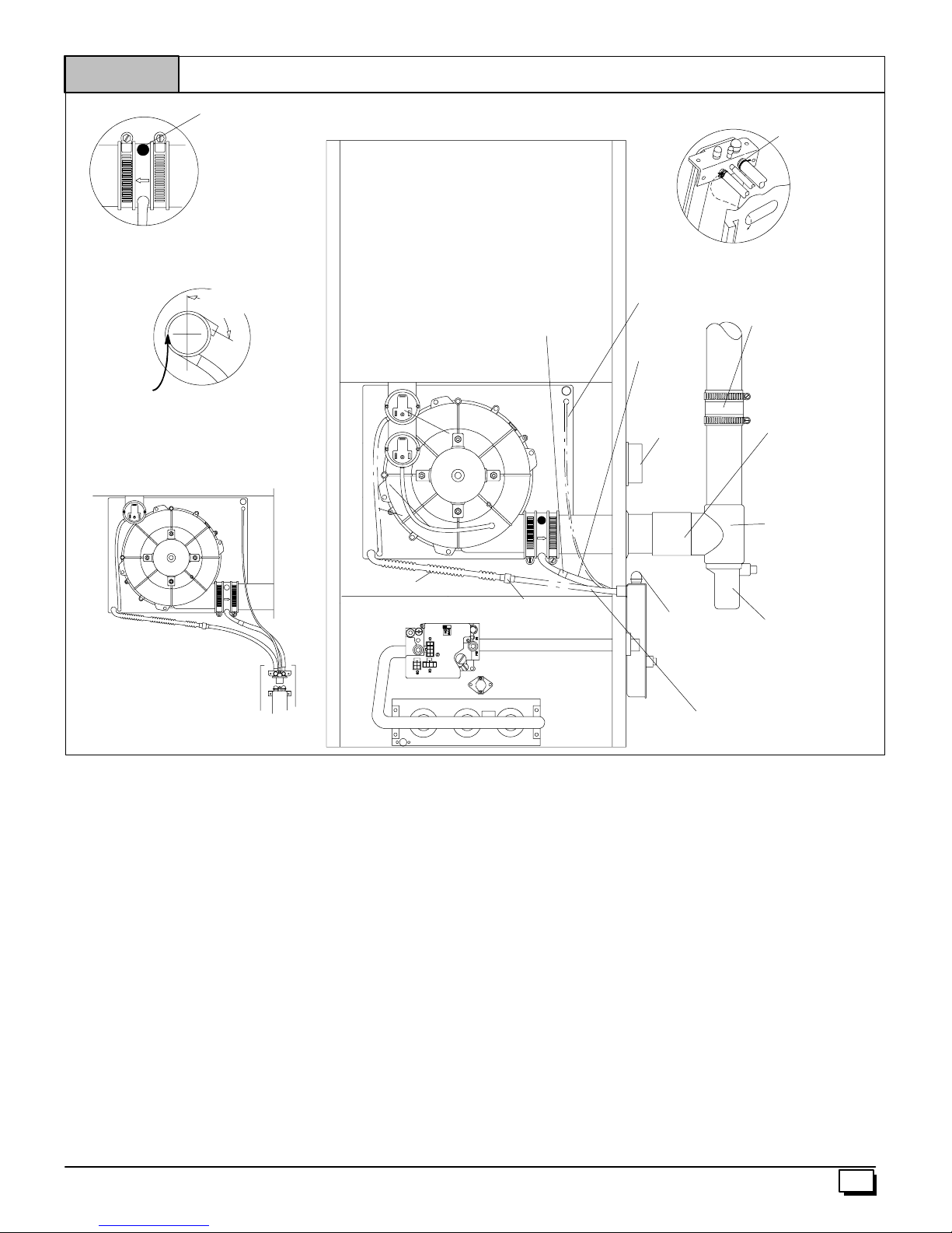
Figure 12
Downflow Right Side Vent and Trap
Yellowor black Plastic
Cap
Vent Drain
&Clamps
SIDE VIEW
Rotate downward
5°°°° to 10°
°
°°
NOTE: Built--in channel will
be angled5° to 10° also.
Single Pressure Switch Detail
Dual Pressure Switch
Splice Connector
Barbed
AIR
FLOW
3
/
²
² ID
²²
16
Rubber Tube
1
/
²
² ID
²²
2
DrainHose&
Clamps
On Some
Models ONLY
INLET
Trap Connection
Preassemble&
insertinto furnace
Coupling & Clamps
(Optional)
“Clampears”
PointedOUT
2²²²² PVC Coupling
Either:ThePVC
Drain Teeor a field
supplied 2²²²² PVC Tee
AIR FLOW
Drain TubeBlack,5/
ID Corrugated
²²²²
8
Downflow Right Side Vent and Trap (See Figure 12)
Remove the Drain Tee if installed.
Disconnect the hoses from the Trap assembly, and remove Trap
and Trap mounting bracket from the blower compartment. Using
cover plate and gasket provided in the loose parts bag, cover the
holefromtheburner compartment to the blowercompartmentand
secure with screws.
Movethecapstothe top of theTrapandmount the Trapexternally
to the right side of the unit using the 2 screws provided.
Connect the corrugated Drain Tube from the transition box to the
Trapasshown. Ifanextensionis required,usethe blackPVCtube
connectorandtheblack
Cut tube to length. Secure all connections with clamps.
ConnectthedrainhosefromtheVentDraintothe Trap. If anextension is required, use the black
ablack
1
/2² ID elbow tube and a suitable section of a1/2² ID drain
tubetomakeconnectionfromtheventdraintothetrap.Secureall
connections with clamps.
5
/8² ID Drain Tubeinthelooseparts bag.
1
/2² OD barbed coupling, connect
Drain ConnectorBlack
3
/
²
² PVC X1/
PVC
²²
4
(Loose partsbag)
²
² CPVC
²²
2
WARNING
Move Caps
TeeTrap White PVC
(loose partsbag)
to top of
trap
Drain Tube,(& Clamps)
5
/
²
² ID Cut to fit
Black,
²²
8
(loose partsbag)
25--24--46
Install the vent pipe grommet into the casing
Cut an appropriate length of 2² PVC pipe long , enough to exitthe
cabinet and connect the vent drain to either:
· A standard field supplied 2² PVC tee (N9MP1 and 2 models), or
· A2² PVC coupling fastened onto the Drain Tee (*9MPD
models)
Install Tee Trap into bottom section of Tee.
Connect the Tee trap and the main drain line exiting the casing as
shown in Figure 1 7.
Note: It is recommended that all PVC piping and fitting connec-
tions be fit up and inspected before final cementing. Both the ex-
ternal Trap and the external Tee Trap must be primed before
operation. Verify all condensate drain connections are securely
clamped. A coupling and clamps (in loose part bag) may be
installed as shown for future servicing of the vent system.
440 01 1020 02
17
 Loading...