

Sears LXI series 934.55156690,LXI series 934.55156690 Owner's Manual
SWAINS
OWNER'S
MANUAL
MODEL NO.
934.55156690
i I i i
VIDEO
CASSETTE
RECORDER
Record the Model Number and Serial Num-
ber of your VCR. The Model Number and
the Serial number are on the rear panel.
Model No.
Serial No.
Keep these numbers for future use.
i
WARNING:
TO REDUCE THE RISK OF FIRE OR ELECTRIC SHOCK, DO NOT EXPOSE THIS APPLIANCE TO RAIN OR
MOISTURE.
CAUTION
A
CAUTION: TO REDUCE THE RISK OF ELECTRIC
SHOCK, DO NOT REMOVE COVER (OR BACK). NO
USER SERVICEABLE PARTS INSIDE. REFER
SERVICING TO QUALIFIED SERVICE PERSON-
NEL.
The caution marking is located on the rear of the cabinet.
A
THIS SYMBOL INDICATES THAT DAN-
GEROUS VOLTAGE CONSTITUTING A
RISK OF ELECTRIC SHOCK IS PRESENT
WITHIN THIS UNIT.
THIS SYMBOL iNDICATES THAT
THERE ARE IMPORTANT OPERATING
AND MAINTENANCE INSTRUCTIONS
IN THE LITERATURE ACCOMPANYING
THE APPLIANCE. ..,
IMPORTANT SAFEGUARDS
1. Read instructions-All the safety and operating instruc-
tions should be read before the appliance is operated.
2. Retain Instructions-The safety and operating instruc-
tions should be retained for future reference.
3. Heed Warnings-All warnings on the appliance and inthe
operating instructions should be adhered to.
4. Follow Instructions-All operating and use instructions
should be followed.
5. Cleaning-Unplug this video product from the wall outlet
before cleaning. Do not use liquid cleaners or aerosol
cleaners. Use a damp cloth for cleaning.
EXCEPTION: A product that is meant for uninter-
rupted service and, that for some specific reason, such as
the possibility of the loss of an authorization code for a
CATV converter, is not intended to be unplugged by the
user for cleaning or any other purpose, may exclude the
reference to unplugging the appliance in the cleaning
description otherwise required in item 5.
6. Attachments-Do not use attachments not recommended by
the video product manufacturer as they may cause hazards.
7. Water and Moisture-Do not use this video product near
water, for example, near a bath tub, wash bowl, kitchen
sink, or laundry tub, in a wet basement, or near a swim-
ming pool, and the like.
8. Accessories-Do not place this video product on an unsta-
ble cart, stand, tripod, bracket, or table. The video product
may fall, causing serious injury to a child or adult, and
serious damage to the appliance. Use only with a cart,
stand, tripod, bracket, or table recommended by the manu-
facturer, or sold with the video PORTASLECARTWARNING
product. Any mounting of the ap-
pliance should follow the manu-
facturer's instructions and should
use amounting accessory recom-
mended by the manufacturer. An
appliance and cart combination
should be moved with care.
Quick stops, excessive force, and
(Symbol provided by RETAC)
uneven surfaces may cause the $3125A
9.
appliafice and cart combination to overturn.
Ventilation-Slots and openings in the cabinet are pro-
vided for ventilation and to ensure reliable operation of
the video product and to protect it from overheating, and
these openings must not be blocked or covered. The
openings should never be blocked by placing the video
product on a bed, sofa, rug, or other similar surface. This
video product should not be placed in a built-in installation
such as a bookcase or rack unless proper ventilation is
provided or the manufacturer's instructions have been
adhered to.
10.
Power Sources-This video product should be operated
only from the type of power source indicated on the
marking label. If you are not sure of the type of power
supply to your home, consult your appliance dealer or
local power company. For products intended to operate
from battery power, or other sources, refer to the operating
instructions.
ll. Grounding or Polarization-This video product is
equipped with a polarized alternating-current line plug (a
plug having one blade wider than the other). This plug will
fit into the power outlet only one way. This is a safety feature.
If you are unable to insert the plug fully into the outlet, try
reversing the plug. If the plug should still fail to fit, contact
your electrician to replace your obsolete outlet. Do not defeat
the safety purpose of the polarized plug.
12. Power Cord Protection-Power supply cords should be
routed so that they are not likely to be walked on or
pinched by items placed upon or against them, paying
particular attention to cords at plugs, convenience recep-
tacles, and the point where they exit from the appliance.
13. Outdoor Antenna Groundlng-lf an outside antenna or
cable system is connected to the video product, be sure the
antenna or cable system is grounded so as to provide some
protection against voltage surges and built-up static
charges. Article 810 of the National Electrical Code,
ANSI/NFPA No. 70, provides information with regard to
proper grounding of the mast and supporting structure,
grounding of the lead-in wire to an antenna discharge unit,
size of grounding conductors, location of antenna-dis-
- 2 - EN
6B01
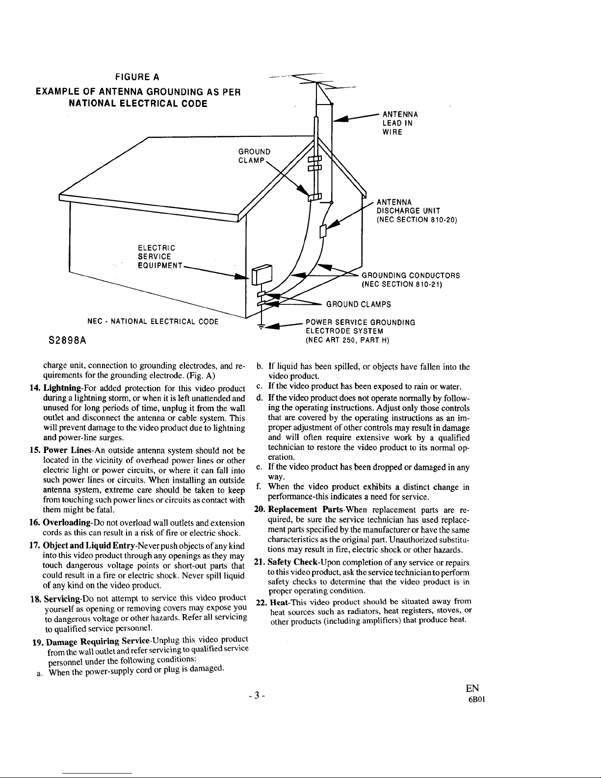
FIGURE A
EXAMPLE OF ANTENNA GROUNDING AS PER
NATIONAL ELECTRICAL CODE
GROUND
CLAMP.
ANTENNA
LEAD IN
WIRE
$2898A
ELECTRIC
SERVICE
EQ
NEC - NATIONAL ELECTRICAL CODE
DISCHARGE UNIT
(NEC SECTION 810-20)
GROUNDING CONDUCTORS
(NEC SECTION 810-21)
GROUND CLAMPS
POWER SERVICE GROUNDING
ELECTRODE SYSTEM
(NEC ART 250, PART H)
charge unit, connection to grounding electrodes, and re-
quirements for the grounding electrode. (Fig. A)
14. Lightning-For added protection for this video product
during a lightning storm, or when it is left unattended and
unused for long periods of time, unplug it from the wall
outlet and disconnect the antenna or cable system. This
will prevent damage to the video product due to lightning
and power-line surges.
15. Power Lines-An outside antenna system should not be
located in the vicinity of overhead power lines or other
electric light or power circuits, or where it can fall into
such power lines or circuits. When installing an outside
antenna system, extreme care should be taken to keep
from touching such power lines or circuits as contact with
them might be fatal.
16. Overloading-Do not overload wall outlets and extension
cords as this can result in a risk of fire or electric shock.
17. Object and Liquid Entry-Never push objects of any kind
into this video product through any openings as they may
touch dangerous voltage points or short-out parts that
could result in a fire or electric shock. Never spill liquid
of any kind on the video product.
18. Servicing-Do not attempt to service this video product
yourself as opening or removing covers may expose you
to dangerous voltage or other hazards. Refer all servicing
to qualified service personnel.
19. Damage Requiring Service-Unplug this video product
from the wall outlet and refer servicing to qualified service
personnel under the following conditions:
a. When the power-supply cord or plug is damaged.
b. If liquid has been spilled, or objects have fallen into the
video product.
c. If the video product has been exposed to rain or water.
d. If the videoproduct does not operate normally by follow-
ing the operating instructions. Adjust only those controls
that are covered by the operating instructions as an im-
proper adjustment of other controls may result in damage
and will often require extensive work by a qualified
technician to restore the video product to its normal op-
eration.
e. If the video product has been dropped or damaged in any
way.
f. When the video product exhibits a distinct change in
performance-this indicates a need for service.
20. Replacement Parts-When replacement parts are re-
quired, be sure the service technician has used replace-
ment parts specified by the manufactureror have the same
characteristics as the original part. Unauthorized substitu-
tions may result in fire, electric shock or other hazards.
21. Safety Check-Upon completion of any service or repairs
tothis video product, ask the service technician toperform
safety checks to determine that the video product is in
proper operating condition.
22. Heat-This video product should be situated away from
heat sources such as radiators, heat registers, stoves, or
other products (including amplifiers) that produce heat.
- 3 - EN
6B01
t:orsale operation and satisfactory perfonnance of your
VCR, keep the following in mind when selecting aplace
for its installation:
• Shield it from direct sunlight and keep it away from
sources of intense heat.
• Avoid dusty or humid places.
• Avoid places with insufficient ventilafion_for proper
heat dissipation. Do not block the ventilation holes
at the top and bottom of the VCR. Do not place the
unit on a carpet because this will block the ventilation
holes.
• Install unit in a horizontal position.
• Avoid locations subject to strong vibration.
• Do not place the VCR near strong magnetic fields.
• Do not move the unit from a cold to a hot place or
vice versa.
• Do not place the VCR directly on top of the TV.
• Do not handle the power cord with wet hands.
• Do not pull on the power cord when disconnecting it
from AC wall outlet. Grasp it by the plug.
• If, by accident, water is spilled on your VCR, unplug
the power cord immediately and take the unit to a
Sears Authorized Service Center for servicing.
• Do not put your fingers or objects into the VCR cas-
sette holder.
• Do not place anything directly on top of the VCR.
Moisture condensation may occur inside the unit when
it is moved from a cold place to a warm place, or after
heating a cold room or under conditions of high humid-
ity. Do not use the VCR at least for 2hours until its inside
is dry.
FCC WARNING- This equipment may generate or use radio frequency energy. Changes or modifications
to this equipment may cause harmful interference unless the modifications are expressly approved in the
instruction manual. The user could lose the authority to operate this equipment if an unauthorized change
or modification is made.
IMPORTANT COPYRIGHT INFORMATION
Unauthorized recording or use of broadcast television programming, video tape, film or other copyrighted
material may violate applicable copyright laws. We assume no responsibility for the unauthorized duplication,
use or otheracts which infringe upon the rights of copyright owners.
The serial number of this product may be found on the back of the VCR. No others have the same serial number
as yours. You should record the number and other vital information here and retain this book as a permanent record
of your purchase to aid identification in case of theft.
Date of Purchase
Dealer Purchase from
Dealer Address
Dealer Phone No.
Model No.
Serial No.
- 4 - EN
6A12
i Ai_iA_ Oi_ L_Ji_ i i_i_ i
• IMPORtaNT _SA_GUARDS ............................ 2
• PRECAUTIONS ................................................... 4
LOCATION .......................................................... 4
AVOID THE HAZARDS OF ELECTRICAL
SHOCK AND FIRE ............................................. 4
WARNING ........................................................... 4
• FEATURES .......................................................... 6
• SUPPLIED ACCESSORIES ............................... 6
• VIDEO CASSETTE TAPE .................................. 7
• OPERATING CONTROLS AND FUNCTIONS.. 8
• PREPARATION FOR USE ............................... I0
CABLE CONNECTIONS .................................. 10
SETlqNG A VIDEO CHANNEL ...................... 11
CONNECTING TO INPUT JACKS .................. 11
A/V TERMINALS .............................................. 11
INSTALLING THE BATTERIES ..................... 11
• MTS (Mu_-C_mnd Te&_n _u_) SYS_M.. 12
CHECKING THE SELECTED MTS MODE .... 12
MTS RECORDING/MONITOR MODE ........... 12
SELECTING THE MTS SYSTEM .................... 13
• PRESET FOR USE ............................................ 14
AUTOMATIC CHANNEL PRESET
(Without a Cable Box) ........................................ 14
TO DELETE PRESET CHANNEL ................... 15
CHANNEL PRESET AGAIN ............................ 15
SEqTING THE CLOCK ................................... 16
SELECTING THE LANGUAGE ...................... 17
• ON SCREENDISPLAY ..................................... 17
I PLAYBACK ........................................................ 18
NORMAL PLAYBACK .................................... 18
• SPECIAL PLAY BACK ...................................... 19
AUTO REPEAT PLAYBACK .......................... 19
RENTAL PLAY ................................................. 19
• SEARCH ............................................................. 20
COUNTER MEMORY ...................................... 20
TIME SEARCH .................................................. 20
INDEX SEARCH .............................................. 21
BLANK SEARCH .............................................. 21
• RECORDING ..................................................... 22
VIEWING AND RECORDING THE SAME
PROGRAM ......................................................... 22
SKIPPING SOME MATERIALS DURING
RECORDING ..................................................... 22
RECORDING ONE PROGRAM WHILE
VIEWING ANOTHER ....................................... 23
TO MONITOR THE PROGRESS OF YOUR
RECORDING ..................................................... 23
OTR (One Touch Recording) ............................. 23
• TIMER RECORDING ....................................... 24
AUTOMATIC TIMER RECORDING ............... 24
QUICK SET PROGRAM ................................... 26
HINTS FOR TIMER RECORDING
(AUTOMATIC TIMER &
QUICK SET PROGRAM) ................................. 27
AUTO RETURN ................................................ 27
JUST-IN TIME RECORDING ........................... 28
• SETTING THE REMAINING TIME ............... 29
• COPYING A VIDEO TAPE ............................... 30
• TROUBLESHOOTING GUIDE ....................... 31
• MAINTENANCE ............................................... 32
• SPECIFICATIONS ............................................ 32
EN
- 5 - 6A12
lti-Ft 5),swm
Rotary 4-head Record/l'layback System
Bilingual on-screen menu display select-
able in English or Spanish
Infrared renwtc control
Real time counter-This shows the elapsed record-
ing or playback time in hours, minutes, and seconds.
The "-" indication will appear when the tape is re-
wound further than the tape counter position
"0:00:00".
181 channel capability PLL frequency syn-
thesizer tuner with direct station call- (A con-
verter may be necessary to view scrambled cable
channels.)
Auto operation features
• Auto power on system when inserting a tape
• Auto counter reset when inserting a tape
• Auto rewind when the end of a tape is reached (not
in the case of timer recording).
l'layback,teatures
• Direct button operation
• 2 step picture search operation ; at a high speed / at a
super high speed
• Still picture
• Digital auto tracking (DTR)
• Auto repeat playback
• Rental play mode
• Time search
• Blank search
• Index search
• Slow motion
• Tape remainder
Recording features
• Three different tape speeds : SP/LP/SLP
• OTR (One Touch Recording)
• Automatic timer recording including Daily &
Weekly
• Quick Set Program
• Auto return
• Just-In-Time Recording
• Edit Search
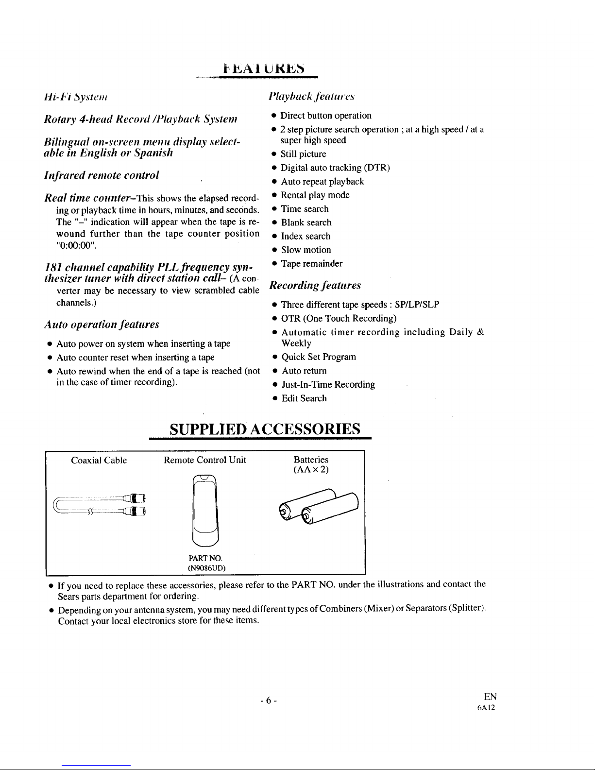
SUPPLIED ACCESSORIES
Coaxial Cable Batteries
(AA × 2)
Remote Control Unit
PART NO.
(N9086UD)
• If you need to replace these accessories, please refer to the PART NO. under the illustrations and contact the
Sears parts department for ordering.
• Depending on your antenna system, you may need different types of Combiners (Mixer) or Separators (Splitter).
Contact your local electronics store for these items.
- 6 - EN
6A12
V liD. O I'AIPE
i
This VCR will operate with any cassette that has the VHS mark. For best results, we recommend the use of
high-quality tapes. Do not use poor quality or damaged tapes.
I'RECA U770NS
• Avoid moisture. Moisture condensation may occur
on the tape if it is moved from a cold place to a warm
place. Before using a tape with these conditions, to
avoid a damage of the tapeand your VCR, wait until
the tape has warmed to room temperature and the
moisture has evaporated.
• Avoid extreme heat, high humidity and magnetic
fields.
• Do not tamper with the cassette mechanism.
• Do not touch the tape with your fingers.
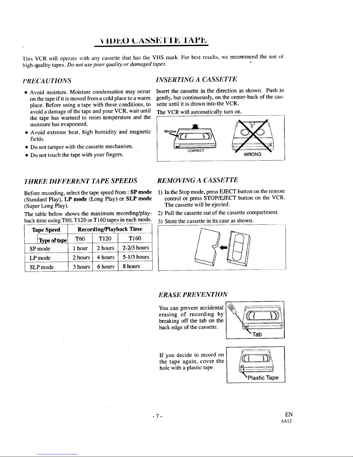
INSERTING A CASSETTE
Insert the cassette in the direction as shown. Push in
gently, but continuously, on the center-back of the cas-
sette until it is drawn into the VCR.
The VCR will automatically turn on.
[ I11 CORRECT --!] _T , "_"
WRONG
THREE I)IFFERENT TAPE SPEEDS
Before recording, select the tape speed from : SP mode
(Standard Play), LP mode (Long Play) or SLP mode
(Super Long Play).
The table below shows the maximum recording/play-
back time using T60, T 120 or T160 tapes in each mode.
Tape Speed
Type of tape
SP mode
LP mode
SLP mode
Recording/Playback Time
T60 T120 T160
1hour 2 hours 2-2/3 hours
2 hours 4 hours 5-1/3 hours
3 hours 6 hours 8 hours
REMOVING A CASSETTE
1) In the Stop mode, press EJECT button on the remote
control or press STOP/EJECT button on the VCR.
The cassette will be ejected.
2) Pull the cassette out of the cassette compartment.
3) Store the cassette in its case as shown.
ERASE PREVENTION
You can prevent accidental
erasing of recording by
breaking off the tab on the
back edge of the cassette.
'Tab
If you decide to record on
the tape again, cover the
hole with a plastic tape.
Plastic Tape
-7- EN
6A12
--FRONT VIEW-- 2 3 4 5
ao 27 7 8 9 10 11 12 13 14 15
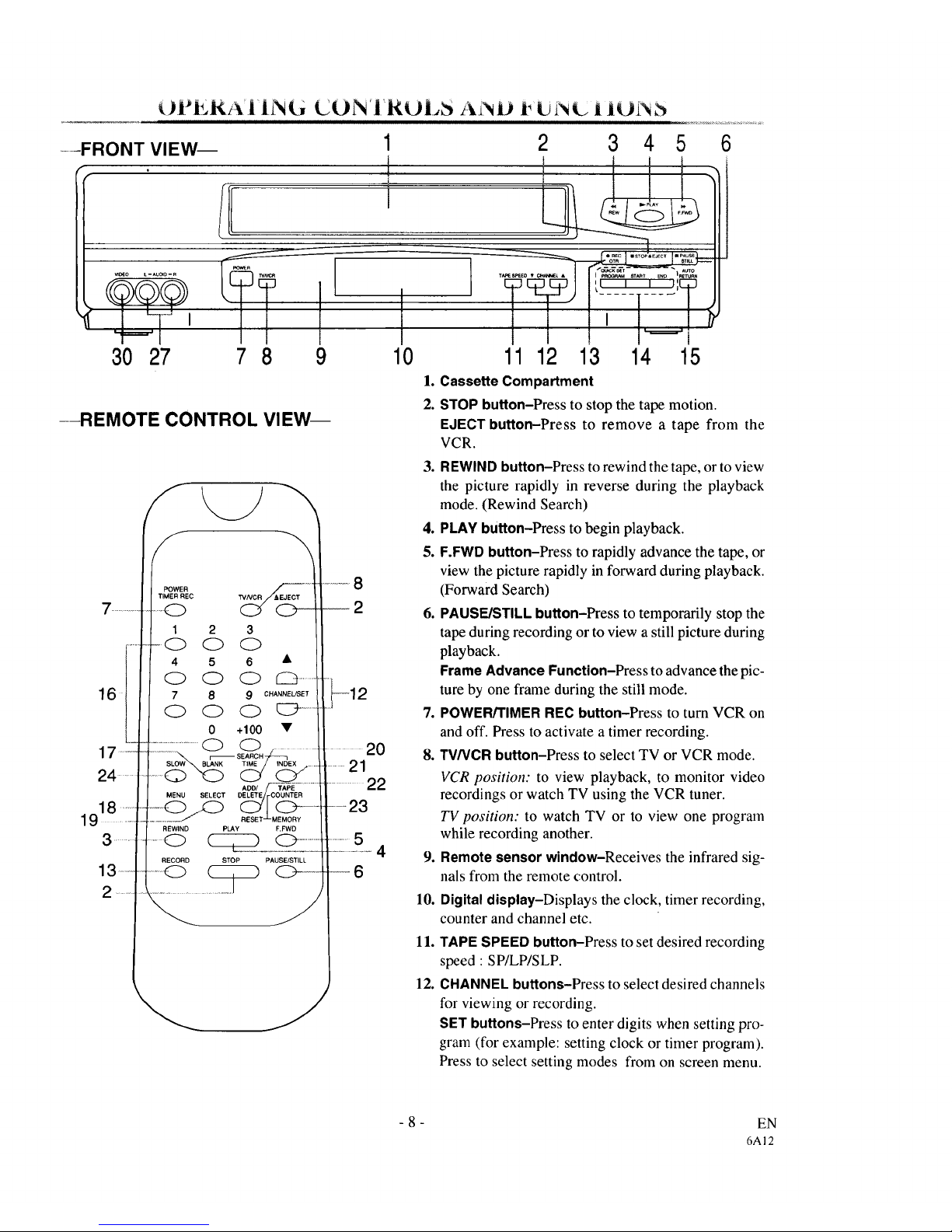
1. Cassette Compartment
2. STOP button-Press to stop the tape motion.
6
--REMOTE CONTROL VIEW--
EJECT button-Press to remove a tape from the
VCR.
..................
6fI
17 ....
24
....
13 ....
....
S
POWER
TIMER RE(;;
1 2 3
-0 0 0
4 5 6 •
7 8 9 CHANNEL/SET
0 0 0 C_ ......
0 +100 •
...................................C_ CD .....
ADD/ -'-TAPE....................
DELETE COUNTER
MENU SELECT _MEM(_ORY. -
REWIND PLAY F.FWD
....o _o ................
RECORD STOP PAUSE/STILL
....O _ _..-..
Y
J
........ 20
......21
.........22
.....23
--6
,
10.
11.
12.
3. REWIND button-Press to rewind the tape, or to view
the picture rapidly in reverse during the playback
mode. (Rewind Search)
4. PLAY button-Press to begin playback.
5. F.FWD button-Press to rapidly advance the tape, or
view the picture rapidly in forward during playback.
(Forward Search)
6. PAUSE/STILL button-Press to temporarily stop the
tape during recording or to view a still picture during
playback.
Frame Advance Function-Press to advance the pic-
ture by one frame during the still mode.
7. POWER/TIMER REC button-Press to turn VCR on
and off. Press to activate a timer recording.
8. TV/VCR button-Press to select TV or VCR mode.
VCR position: to view playback, to monitor video
recordings or watch TV using the VCR tuner.
TV position: to watch TV or to view one program
while recording another.
Remote sensor window-Receives the infrared sig-
nals from the remote control.
Digital display-Displays the clock, timer recording,
counter and channel etc.
TAPE SPEED button-Press to set desired recording
speed : SP/LP/SLP.
CHANNEL buttons-Press to select desired channels
for viewing or recording.
SET buttons-Press to enter digits when setting pro-
gram (for example: setting clock or timer program).
Press to select setting modes from on screen menu.
-8-
EN
6A12
-REAR VIEW-
25 26 27 28
I]I] O DI]DOI]rll]I ]I]
i
i
L
-,ooo-
VIDEO I_
29 30 31 32
"t
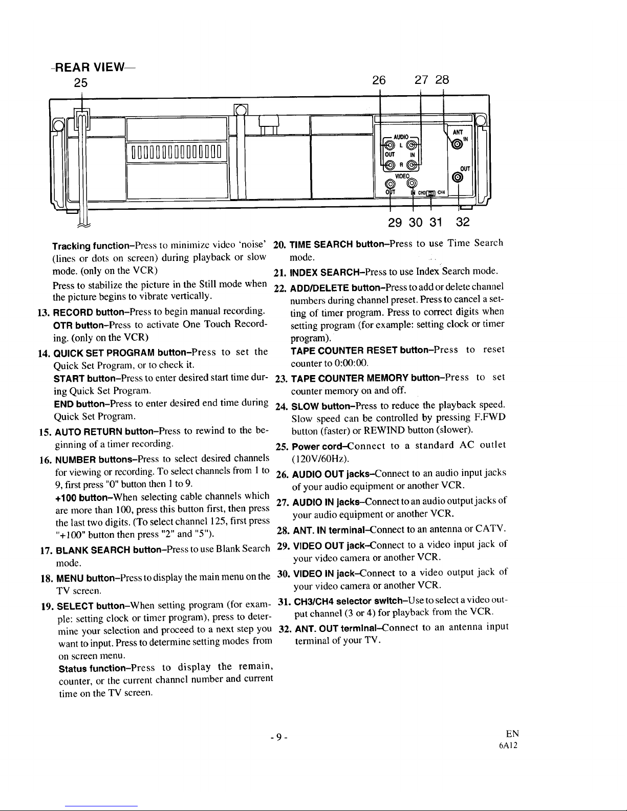
Tracking function-Press to minimize video 'noise' 20.
(lines or dots on screen) during playback or slow
mode. (only on the VCR) 21.
Press to stabilize the picture in the Still mode when
22.
the picture begins to vibrate vertically.
13. RECORD button-Press to begin manual recording.
OTR button-Press to activate One Touch Record-
ing. (only on the VCR)
14. QUICK SETPROGRAM button-Press to set the
Quick Set Program, or to check it.
START button-Press to enter desired start time dur- 23.
ing Quick Set Program.
END button-Press to enter desired end time during 24.
Quick Set Program.
15. AUTO RETURN button-Press to rewind to the be-
ginning of a timer recording. 25.
16. NUMBER buttons-Press to select desired channels
for viewing or recording. To select channels from 1 to 26.
9, first press "0" button then 1 to 9.
÷100 button-When selecting cable channels which
27.
are more than 100, press this button first, then press
the last two digits. (To select channel 125, first press
"+100" button then press "2" and "5"). 28.
17. BLANK SEARCH button-Press to use Blank Search 29.
mode.
30.
31.
18. MENU button-Press to display the main menu on the
TV screen.
19. SELECT button-When setting program (for exam-
ple: setting clock or timer program), press to deter-
mine your selection and proceed to a next step you 32.
want to input. Press to determine setting modes from
on screen menu.
Status function-Press to display the remain,
counter, or the current channel number and current
time on the TV screen.
TIME SEARCH button-Press to use Time Search
mode. .
INDEX SEARCH-Press to use Index'Search mode.
ADD/DELETE button-Press to add or delete channel
numbers during channel preset. Press to cancel a set-
ting of timer program. Press to correct digits when
setting program (for example: setting clock or timer
program).
TAPE COUNTER RESET button-Press to reset
counter to 0:00:00.
TAPE COUNTER MEMORY button-Press to set
counter memory on and off.
SLOW button-Press to reduce the playback speed.
Slow speed can be controlled by pressing F.FWD
button (faster) or REWIND button (slower).
Power cord-Connect to a standard AC outlet
(120VI60Hz).
AUDIO OUT jacks-Connect to an audio input jacks
of your audio equipment or another VCR.
AUDIOINjacks--Connect to an audio output jacks of
your audio equipment or another VCR.
ANT. IN terminal--Connect to an antenna or CATV.
VIDEOOUT jack-Connect to a video input jack of
your video camera or another VCR.
VIDEOINjack-Connect to a video output jack of
your video camera or another VCR.
CH3/CH4 selector switch-Use to select a video out-
put channel (3 or 4) for playback from the VCR.
ANT. OUT terminal--Connect to an antenna input
terminal of your TV.
- 9 - EN
6A12
i_.RLI_ARAI I¢0N I_O.R U_E
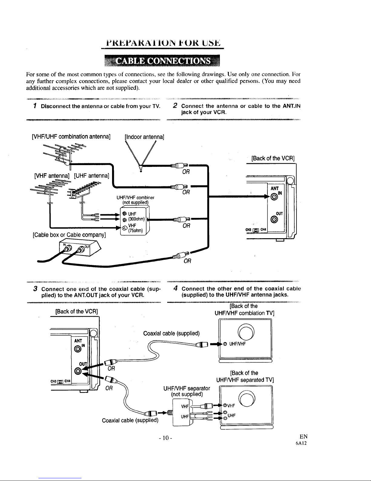
For some of the most common types of connections, see the following drawings. Use only one connection. For
any further complex connections, please contact your local dealer or other qualified persons. (You may need
additional accessories which are not supplied).
1 Disconnectthe antenna or cable fromyour TV. 2 Connect the antenna or cable to the ANT.IN
jack ofyour VCR.
[VHF/UHFcombinationantenna] [Indoor antenna]
[Cable boxor Cablecompany]
_m
OR
m
OR
m
OR
• I
[Backof theVCR
ANT
' = _}IN
OUT
0
013 _ CH4 __
3
Connect one end of the coaxial cable (sup-
plied) to the ANT.OUTjack of your VCR.
[Backof theVCR
ANT "_
OUT
oclc
4 Connect the other end of the coaxial cable
(supplied) to the UHF/VHFantenna jacks.
[Backofthe
UHFNHF combiationTV
Coaxialcable(supplied)
©
_O UHFNHF
"= OR
=, : [Backofthe
cmr_cm _ _ JHF/VHFseparatedTV:
-- _ -/ OR _'_ UHFNHF separator [ = _ ]
(J(J (n°tsupplied) ! LI
Coaxial cable(supplied) _ "__ !.
- 10- EN
6AI2
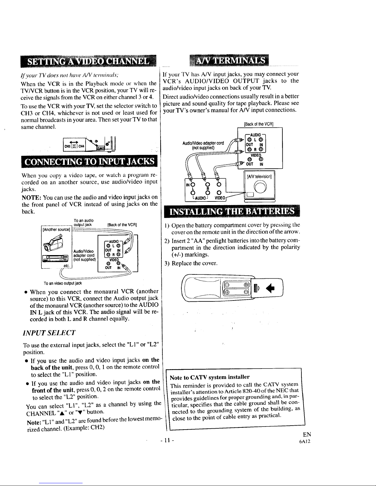
If your TV does not have A/V terminals;
When the VCR is in the Playback mode or when the
TV/VCR button is in the VCR position, your TV will re-
ceive the signals from the VCR on either channel 3 or 4.
To use the VCR with your TV, set the selector switch to
CH3 or CH4, whichever is not used or least used for
normal broadcasts in your area. Then set your TV to that
same channel.
When you copy a video tape, or watch a prograln re-
corded on an another source, use audio/video input
jacks.
NOTE: You can use the audio and video input jacks on
the front panel of VCR instead of using jacks on the
back.
TOan audio
adaptercord _0 R_] l
I_ (notsupplied) VlDE_ |
L- _1
To an videooutputJack
• When you connect the monaural VCR (another
source) to this VCR, connect the Audio output jack
of the monaural VCR (another source) to the AUDIO
IN L jack of this VCR. The audio signal will be re-
corded in both L and R channel equally.
INPUT SELECT
To use the external input jacks, select the "LI" or "L2"
position.
• If you use the audio and video input jacks on the
back of the unit, press 0, 0, 1 on the remote control
to select the "LI" position.
• If you use the audio and video input jacks on the
front of the unit, press 0, 0, 2 on the remote control
to select the "L2" position.
You can select "LI", "L2" as a channel by using the
CHANNEL "A" or "V" button.
Note: "LI" and "L2" are found before the lowest memo-
rized channel. (Example: CH2)
If your TV has A/V input jacks, you may connect your
VCR's AUDIO/VIDEO OUTPUT jacks to the
audio/video input jacks on back of your TV.
Direct audio/video connections usually result in a better
picture and sound quality for tape playback. Please see
yourTV's owner's manual for A/V input connections.
[BackoftheVCR]
Au::lioNideo__ adaptercord n_'-n=oI;ULDIOI@M_
1) Open the battery compartment cover by pressing the
cover on the remote unit in the direction of the arrow.
2) Insert 2 "AA" penlight batteries into the battery com-
partment in the direction indicated by the polarity
(+/-) markings.
3) Replace the cover.
Note to CATV system installer
This reminder is provided to call the CATV system
installer's attention to Article 820-40 of the NEC that
provides guidelines for proper grounding and, in par-
ticular, specifies that the cable ground shall be con-
nected to the grounding system of the building, as
close to the point of cable entry as practical.
EN
-11- 6A12
 Loading...