

Sears LXI series 580.55154490,LXI series 580.55154490 Owner's Manual
$ I It i _ $
OWNERS
MANUAL
MODEL NO.
580.55154490
KNOW YOUR UNIT
Read this booklet so you will be
able toenjoyall the features inyour
video cassette recorder.
Record in space provided below
the Model No. andthe Serial No.
as found on the rear of your video
cassette recorder.
Model No.
Serial No.
Retain this information for future
reference.
[vgs]
VIDEO CASSETTE
RECORDER
Operation
Sears, Roebuck and Co., Hoffman Estates, IL 60179. U.S.A.
WARNING:
TO PREVENT FIRE OR SHOCK HAZARD, DO NOT
EXPOSE THIS APPLIANCE TO RAIN OR MOISTURE.
[,o,I:_lljnlll[o]_
RISK OF ELECTRIC SHOCK
DO NOT OPEN
CAUTION: TO REDUCE THE RISK OF ELECTRIC SHOCK.
DO NOT REMOVE COVER (OR BACK).
NO USER-SERVICEABLE PARTS INSIDE.
REFER SERVICING TO QUALIFIED SERVICE
PERSONNEL.
The exclamation point within an equilateral triangle
is intended to alert the user to the presence of
important operating and maintenance (servicing)
instructions in the literature accompanying the
product.
The lightning flash with arrowhead symbol, within
an equilateral triangle, is intended to alert the user
to the presence of uninsulated "dangerous
voltage" within the product's enclosure that may be
of sufficient magnitude to constitute a risk of
electric shock to persons.
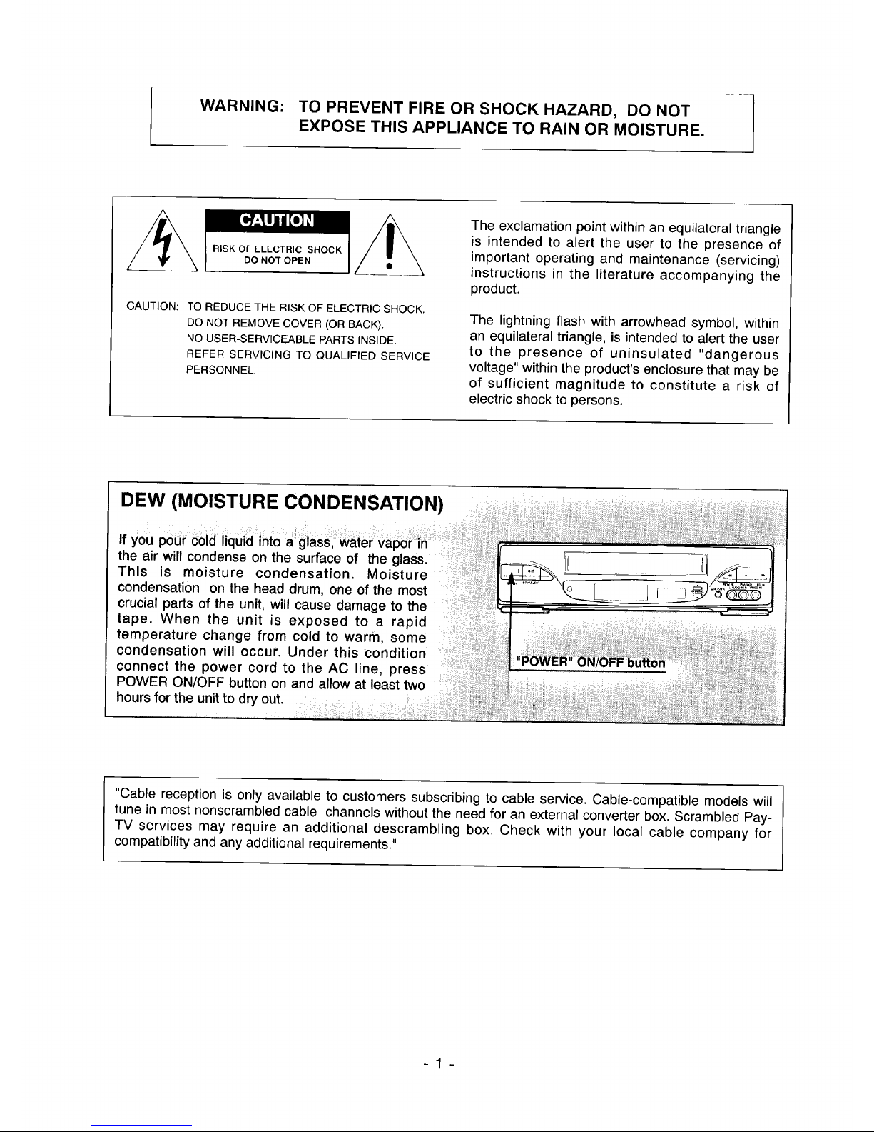
DEW (MOISTURE CONDENSATION)
If you pour cold liquid into a glass, water vapor _in
the air will condense on the surface of the glass.
This is moisture condensation. Moisture
condensation on the head drum, one of the most
crucial parts of the unit, will cause damage to the
tape. When the unit is exposed to a rapid
temperature change from cold to warm, some
condensation will occur. Under this condition
connect the power cord to the AC line, press
POWER ON/OFF button on and allow at least two
hours for the unit to out.
©
"Cable reception is only available to customers subscribing to cable service. Cable-compatible models will
tune in most nonscrambled cable channels without the need for an external converter box. Scrambled Pay-
TV services may require an additional descrambling box. Check with your local cable company for
compatibility and any additional requirements."
-1-
Congratulations on buying the _ Video Cassette Recorder (VCR). For your convenience, please read
these simple instructions before operating your VCR.
NOTES:, This Video Cassette Recorder is compatible with any video cassette bearing the _ mark.
. I_ is designed to expand your opportunities for in-home TV viewing and not for any usage
which might violate the copyright laws.
, _ The Video Cassette Recorder (VCR) with this marking incorporates _ high-quality
picture technology and is compatible with any Video Cassette Recorders bearing
the I_/_ mark.
Check to make sure you have the following acces-
sories before disposing of the packing material.
1. 75-ohm Coaxial Cable with Antenna Adaptor
(75/300-ohm)
2. Remote Control
3. Audio connection cable
4. Video connection cable
TABLE OF CONTENTS
Important Safety Instructions .............. 3
Installation ............................. 5
Wiring diagram .......................... 5
Antenna/VCR connections ................. 6
VCR/'rv connections ..................... 7
Cable antenna (CATV) connections .......... 8
On screen display ....................... 9
Identification and operation of controls ..... 10
MBR (Multi Brand Remote) remote control • • •14
Set your television to the VCR channel ...... 20
On Screen Menu features ................. 21
Channel presetting
(By using the remote control) ............. 24
Viewing TV only ........................ 26
Video Cassette Tapes .................... 27
Cassette Loading and Unloading ........... 27
Clock setting (By using the remote control) • •28
Calendar .............................. 30
Normal Playback ....................... 31
Visual search (F-Search and R-Search) ...... 32
Pause/Still ............................. 33
Frame advance ......................... 33
Double speed playback .................. 33
Slow ................................. 34
Auto playback function .................. 34
VISS (VHS Index search system)/
TIME Search ........................... 35
Making a sample recording ............... 36
Recording while you are away ............. 37
Program timer setting
(You must use the remote control) ......... 38
VCR PlusTM+Programming/Recording ....... 43
Instant Timer Recording (ITR) ............. 50
Recording one program while viewing
Another ............................... 51
Editing a recording ...................... 51
Using the counter memory feature ......... 52
Hi-Fi audio sound system ................ 53
Stereo recording/Playback connections
and operation .......................... 54
SAP (Second audio program)
record ingNiewing ...................... 55
Multi-channel TV sound (MTS) ............. 56
Auto-rewind ........................... 58
Auto memory power shut-off .............. 58
Playback with "rv equipped with VIR ........ 58
Video head Cleaning .................... 58
Operating hints ......................... 59
VCR to VCR dubbing .................... 59
Troubleshooting ........................ 60
Routine maintenance .................... 62
Sears service .......................... 62
How to order repair parts ................. 62
Specifications .......................... 63
Features .............................. 63
Warranty....................... RearCover
-2-
IMPORTANT SAFETY INSTRUCTIONS
1. Read Instructions-All the safety and
operating instructions should be read before
the product is operated.
2. Retain Instructions-The safety and operating
instructions should be retained for future
reference.
3. Heed Warnings-A_l warnings on the product
and in the operating instructions should be
adhered to.
4. Follow Instructions-All operating and use
instructions should be followed.
5. Cleaning-Unplug this product from the wall
outlet before cleaning. Do not use liquid
cleaners or aerosol cleaners. Use a damp
cloth for cleaning.
Exception: A product that is meant for
uninterrupted service and that for some
specific reason, such as the possibility of the
loss of an authorization code for a CATV
converter, is not intended to be unplugged by
the user for cleaning or any other purpose,
may exclude the reference to unplugging the
product in the cleaning description otherwise
required in item 5.
6. Attachments-Do not use attachments not
recommended by the product manufacturer as
they may cause hazards.
7. Water and Moisture-Do not use this product
near water- for example, near a bath tub,
wash bowl, kitchen sink, or laundry tub; in a
wet basement; or near a swimming pool; and
the like.
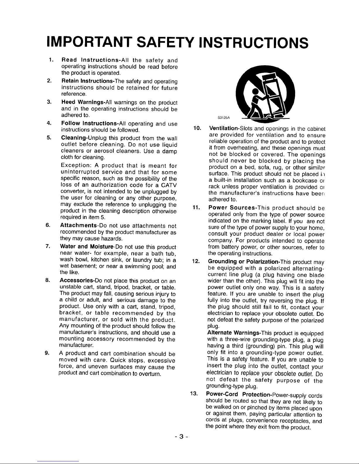
8. Accessories-Do not place this product on an
unstable cart, stand, tripod, bracket, or table.
The product may fall, causing serious injury to
a child or adult, and serious damage to the
product. Use only with a cart, stand, tripod,
bracket, or table recommended by the
manufacturer, or sold with the product.
Any mounting of the product should follow the
manufacturer's instructions, and should use a
mounting accessory recommended by the
manufacturer.
9. A product and cart combination should be
moved with care. Quick stops, excessive
force, and uneven surfaces may cause the
product and cart combination to overturn.
-3-
S3125A
10. Ventilation-Slots and openings in the cabinet
are provided for ventilation and to ensure
reliable operation of the product and to protect
it from overheating, and these openings must
not be blocked or covered. The openings
should never be blocked by placing the
product on a bed, sofa, rug, or other similsr
surface. This product should not be placed i,-=
a built-in installation such as a bookcase o_
rack unless proper ventilation is provided or
the manufacturer's instructions have beer_
adhered to.
11. Power Sources-This product should be
operated only from the type of power source
indicated on the marking label. If you are not
sure of the type of power supply to your home,
consult your product dealer or local power
company. For products intended to operate
from battery power, or other sources, refer to
the operating instructions.
12. Grounding or Polarization-This product may
be equipped with a polarized alternating-
current line plug (a plug having one blade
wider than the other). This plug will fit into the
power outlet only one way. This is a safety
feature. If you are unable to insert the plug
fully into the outlet, try reversing the plug. If
the plug should still fail to fit, contact your
electrician to replace your obsolete outlet. Do
not defeat the safety purpose of the polarized
plug.
Alternate Warnings-This product is equipped
with a three-wire grounding-type plug, a plug
having a third (grounding) pin. This plug will
only fit into a grounding-type power outlet.
This is a safety feature. If you are unable to
insert the plug into the outlet, contact your
electrician to replace your obsolete outlet. Do
not defeat the safety purpose of the
grounding-type plug.
13. Power-Cord Protection-Power-supply cords
should be routed so that they are not likely to
be walked on or pinched by items placed upon
or against them, paying particular attention to
cords at plugs, convenience receptacles, and
the point where they exit from the product.
14.
15.
Protective Attachment Plug-The product is
equipped with an attachment plug having
overload protection. This is a safety feature.
See Instruction Manual for replacement or
resetting of protective device. If replacement
of the plug is required, be sure the service
technician has used a replacement plug
specified by the manufacturer that has the
same overload protection as the original plug.
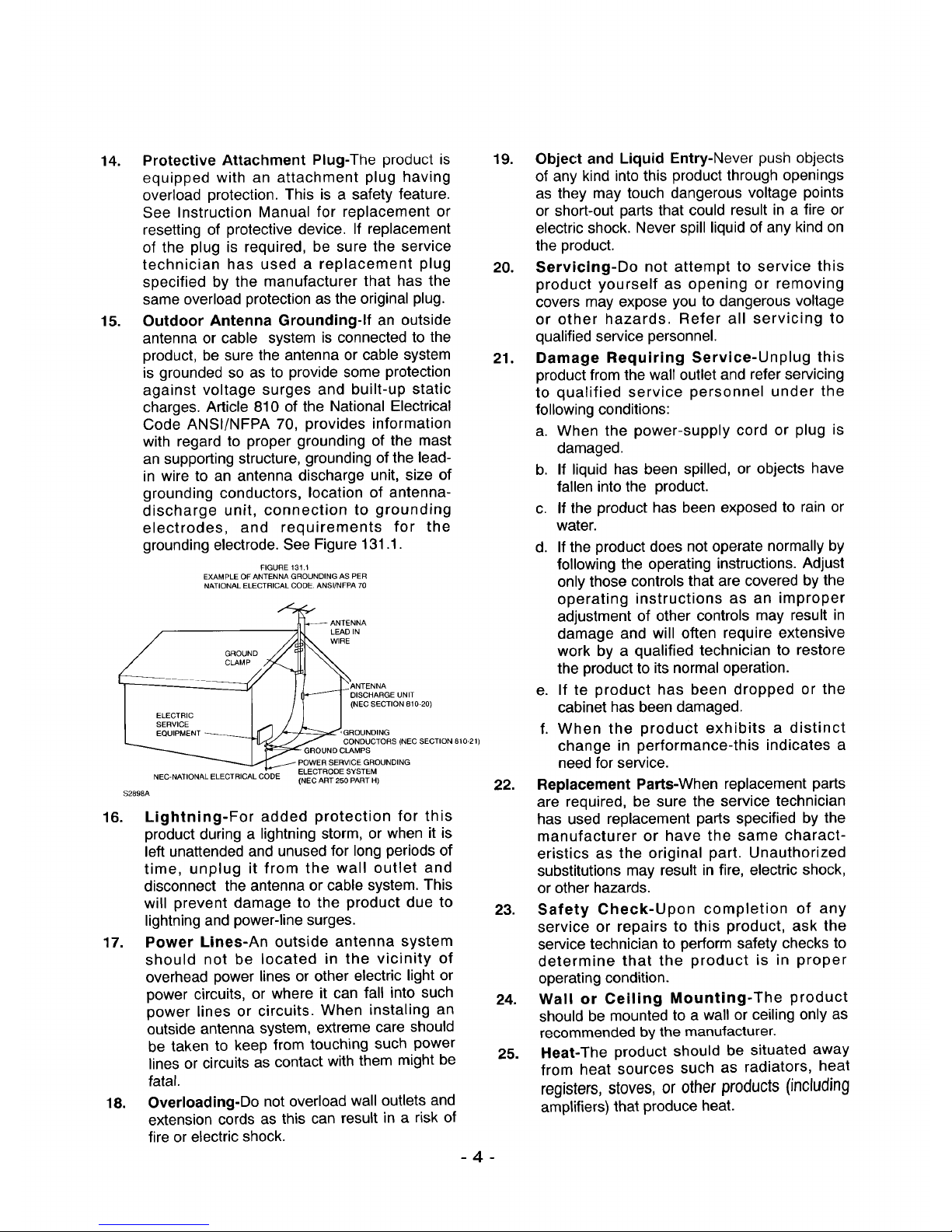
Outdoor Antenna Grounding-If an outside
antenna or cable system is connected to the
product, be sure the antenna or cable system
is grounded so as to provide some protection
against voltage surges and built-up static
charges. Article 810 of the National Electrical
Code ANSI/NFPA 70, provides information
with regard to proper grounding of the mast
an supporting structure, grounding of the lead-
in wire to an antenna discharge unit, size of
grounding conductors, location of antenna-
discharge unit, connection to grounding
electrodes, and requirements for the
grounding electrode. See Figure 131.1.
FIGURE 131.1
EXAMPLE OF ANTENNA GROUNDING AS PER
NATIONAL ELECTRICAL CODE. ANSI/NFPA 70
ANTENNA
LEAD IN
WIRE
c_F- .5
DISCHARGE UNIT
I = oto.cI- / / <"'°s'c''°"°'"°>
L EQUrf_4_ENT _ _ _'_"_'CG_NODUN([_/NGs(NEcSECTION810.21)
I '¢ G.OUNOc .PS
PowerSERV,OEGRDU.O,NG
ELECTRODE SYSTEM
NEC-NATIONAL ELECTRICAL CODE (NEC ART 250 PART H)
$2898A
16. Lightning-For added protection for this
product during a lightning storm, or when it is
left unattended and unused for long periods of
time, unplug it from the wall outlet and
disconnect the antenna or cable system. This
will prevent damage to the product due to
lightning and power-line surges.
17. Power Lines-An outside antenna system
should not be located in the vicinity of
overhead power lines or other electric light or
power circuits, or where it can fall into such
power lines or circuits. When instaling an
outside antenna system, extreme care should
be taken to keep from touching such power
lines or circuits as contact with them might be
fatal.
18. Overloading-Do not overload wall outlets and
extension cords as this can result in a risk of
fire or electric shock.
19. Object and Liquid Entry-Never push objects
of any kind into this product through openings
as they may touch dangerous voltage points
or short-out parts that could result in a fire or
electric shock. Never spill liquid of any kind on
the product.
20. Servicing-Do not attempt to service this
product yourself as opening or removing
covers may expose you to dangerous voltage
or other hazards. Refer all servicing to
qualified service personnel.
21. Damage Requiring Service-Unplug this
product from the wall outlet and refer servicing
to qualified service personnel under the
following conditions:
a. When the power-supply cord or plug is
damaged.
b. If liquid has been spilled, or objects have
fallen into the product.
c. If the product has been exposed to rain or
water.
-4-
22.
d. If the product does not operate normally by
following the operating instructions. Adjust
only those controls that are covered by the
operating instructions as an improper
adjustment of other controls may result in
damage and will often require extensive
work by a qualified technician to restore
the product to its normal operation.
e. If te product has been dropped or the
cabinet has been damaged.
f. When the product exhibits a distinct
change in performance-this indicates a
need for service.
Replacement Parts-When replacement parts
are required, be sure the service technician
has used replacement parts specified by the
manufacturer or have the same charact-
eristics as the original part. Unauthorized
substitutions may result in fire, electric shock,
or other hazards.
23. Safety Check-Upon completion of any
service or repairs to this product, ask the
service technician to perform safety checks to
determine that the product is in proper
operating condition.
24. Wall or Ceiling Mounting-The product
should be mounted to a wall or ceiling only as
recommended by the manufacturer.
25. Heat-The product should be situated away
from heat sources such as radiators, heat
registers, stoves, or other products (including
amplifiers) that produce heat.
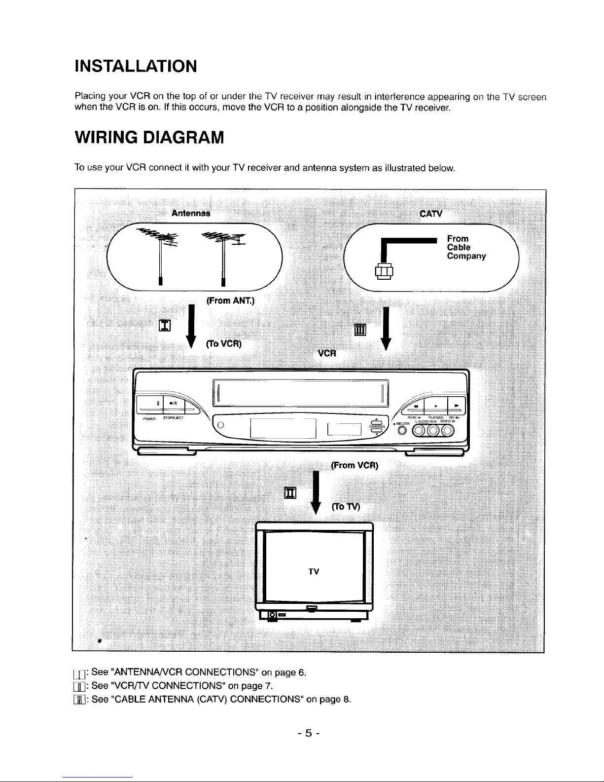
INSTALLATION
Placing your VCR on the top of or under the TV receiver may result in interference appearing on the TV screen
when the VCR is on. If this occurs, move the VCR to a position alongside the TV receiver.
WIRING DIAGRAM
To use your VCR connect it with your TV receiver and antenna system as illustrated below.
_. JJ
1_ From
Cable
Company
® )
°!
(From ANT.)
(ToVCR)
VCR
t"
ill
F
(FromVCR)
I_ _ (To_
TV
i,:
[j_: See "ANTENNA/VCR CONNECTIONS" on page 6.
[_q: See "VCR/TV CONNECTIONS" on page 7.
[j]_: See "CABLE ANTENNA (CATV) CONNECTIONS" on page 8.
-5-
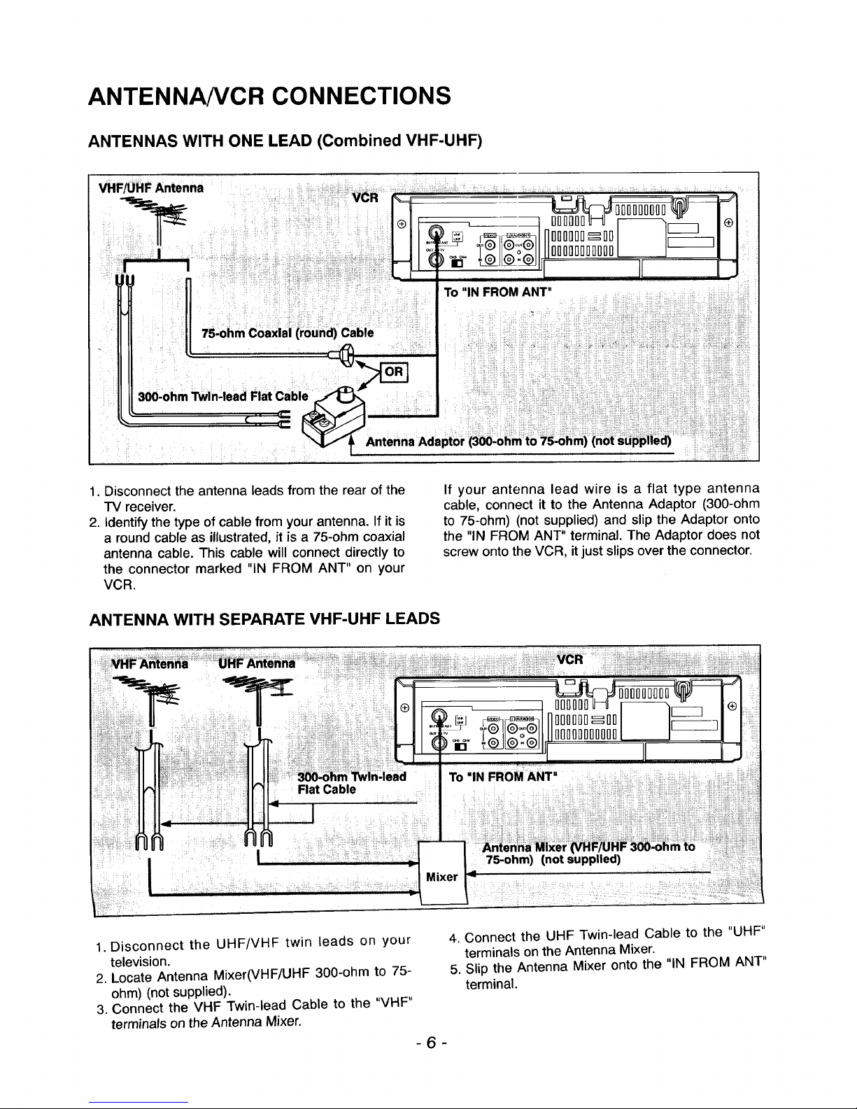
ANTENNA/VCR CONNECTIONS
ANTENNAS WITH ONE LEAD (Combined VHF-UHF)
VHF/UHF Antenna
.......
VCR
O000nDnDo00_ I I
®J hl, II IIJ
To "INFROM ANT"
1. Disconnect the antenna leads from the rear of the
TV receiver.
2. Identify the type of cable from your antenna. If it is
a round cable as illustrated, it is a 75-ohm coaxial
antenna cable. This cable will connect directly to
the connector marked "IN FROM ANT" on your
VCR.
ANTENNA WITH SEPARATE VHF-UHF LEADS
If your antenna lead wire is a flat type antenna
cable, connect it to the Antenna Adaptor (300-ohm
to 75-ohm) (not supplied) and slip the Adaptor onto
the "IN FROM ANT" terminal. The Adaptor does not
screw onto the VCR, it just slips over the connector.
1. Disconnect the UHF/VHF twin leads on your
television.
2. Locate Antenna Mixer(VHF/UHF 300-ohm to 75-
ohm) (not supplied).
3. Connect the VHF Twin-lead Cable to the "VHF"
terminals on the Antenna Mixer.
-6-
4. Connect the UHF Twin-lead Cable to the "UHF"
terminals on the Antenna Mixer.
5. Slip the Antenna Mixer onto the "IN FROM ANT"
terminal.
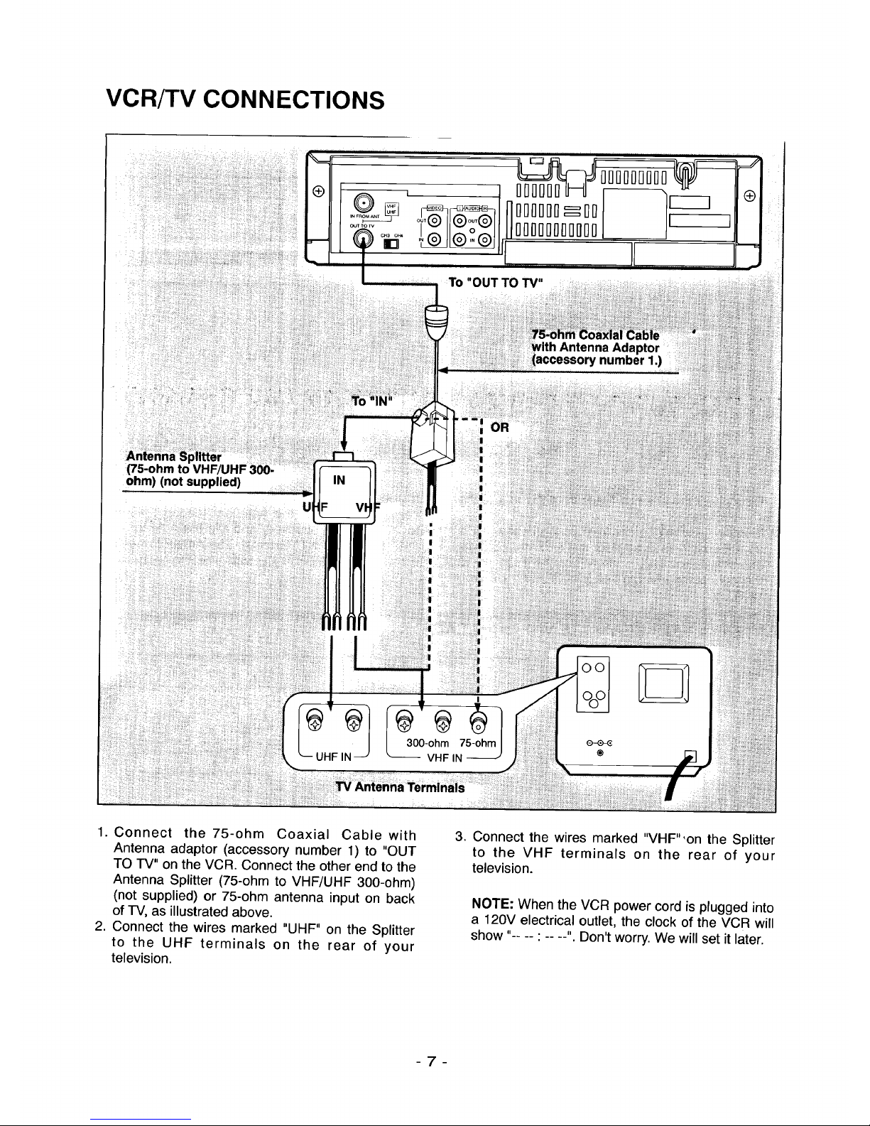
VCR/TV CONNECTIONS
:To "OUT TO TV"
Antenna Adaptor
accessory number 1.)
(75-ohm to
ohm) (not supplied)
UHF IN
300-ohm 75-ohm
VHF IN
®
1. Connect the 75-ohm Coaxial Cable with
Antenna adaptor (accessory number 1) to "OUT
TO TV" on the VCR. Connect the other end to the
Antenna Splitter (75-ohm to VHF/UHF 300-ohm)
(not supplied) or 75-ohm antenna input on back
of TV, as illustrated above.
2. Connect the wires marked "UHF" on the Splitter
to the UHF terminals on the rear of your
television.
3. Connect the wires marked "VHF"'on the Splitter
to the VHF terminals on the rear of your
television.
NOTE: When the VCR power cord is plugged into
a 120V electrical outlet, the clock of the VCR will
show ..... . Don't worry. We will set it later.
-7-
CABLE ANTENNA (CATV) CONNECTION5
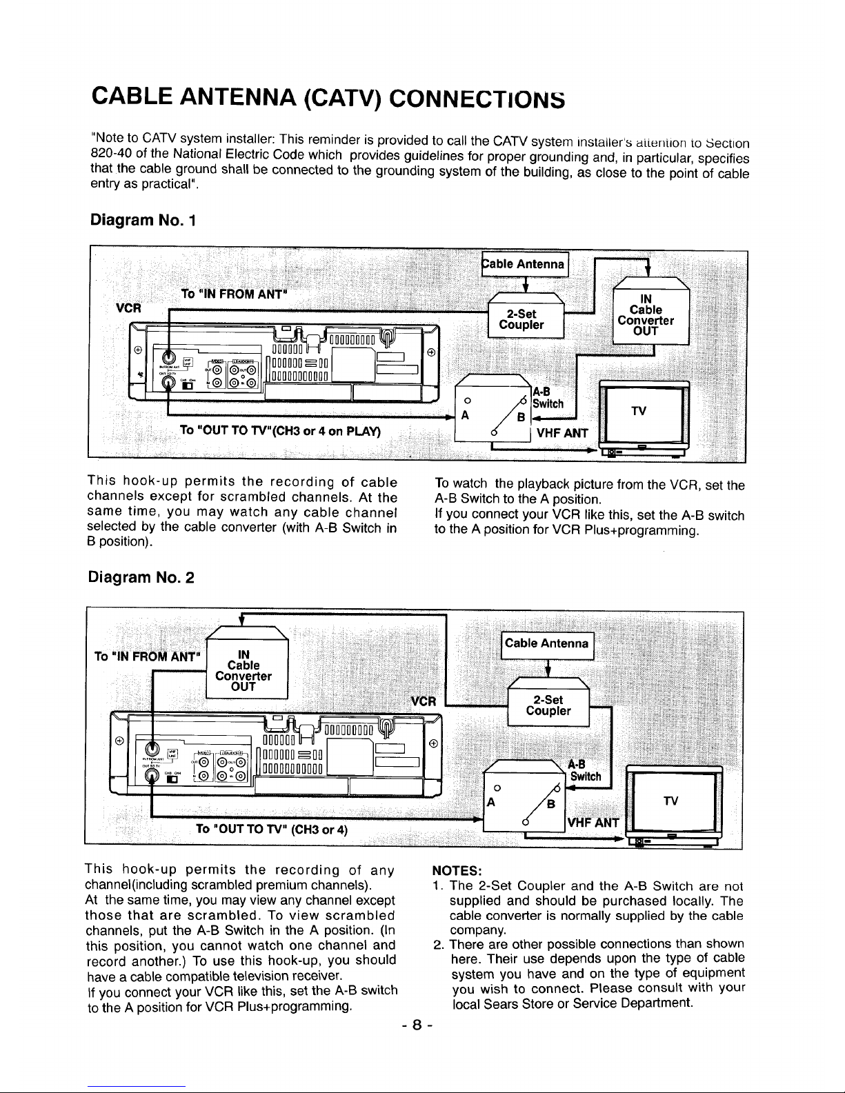
"Note to CATV system installer: This reminder is provided to call the CATV system instailer's atLention to _Sectlon
820-40 of the National Electric Code which provides guidelines for proper grounding and, in particular, specifies
that the cable ground shall be connected to the grounding system of the building, as close to the point of cable
entry as practical".
Diagram No. 1
This hook-up permits the recording of cable
channels except for scrambled channels. At the
same time, you may watch any cable channel
selected by the cable converter (with A-B Switch in
B position).
Diagram No. 2
To watch the playback picture from the VCR, set the
A-B Switch to the A position.
If you connect your VCR like this, set the A-B switch
to the A position for VCR Plus+programming.
This hook-up permits the recording of any
channel(including scrambled premium channels).
At the same time, you may view any channel except
those that are scrambled. To wew scrambled
channels, put the A-B Switch in the A position. (In
this position, you cannot watch one channel and
record another.) To use this hook-up, you should
have a cable compatible television receiver.
If you connect your VCR like this, set the A-B switch
to the A position for VCR Plus+programming.
NOTES:
1. The 2-Set Coupler and the A-B Switch are not
supplied and should be purchased locally. The
cable converter is normally supplied by the cable
company.
2. There are other possible connections than shown
here. Their use depends upon the type of cable
system you have and on the type of equipment
you wish to connect. Please consult with your
local Sears Store or Service Department.
-8-
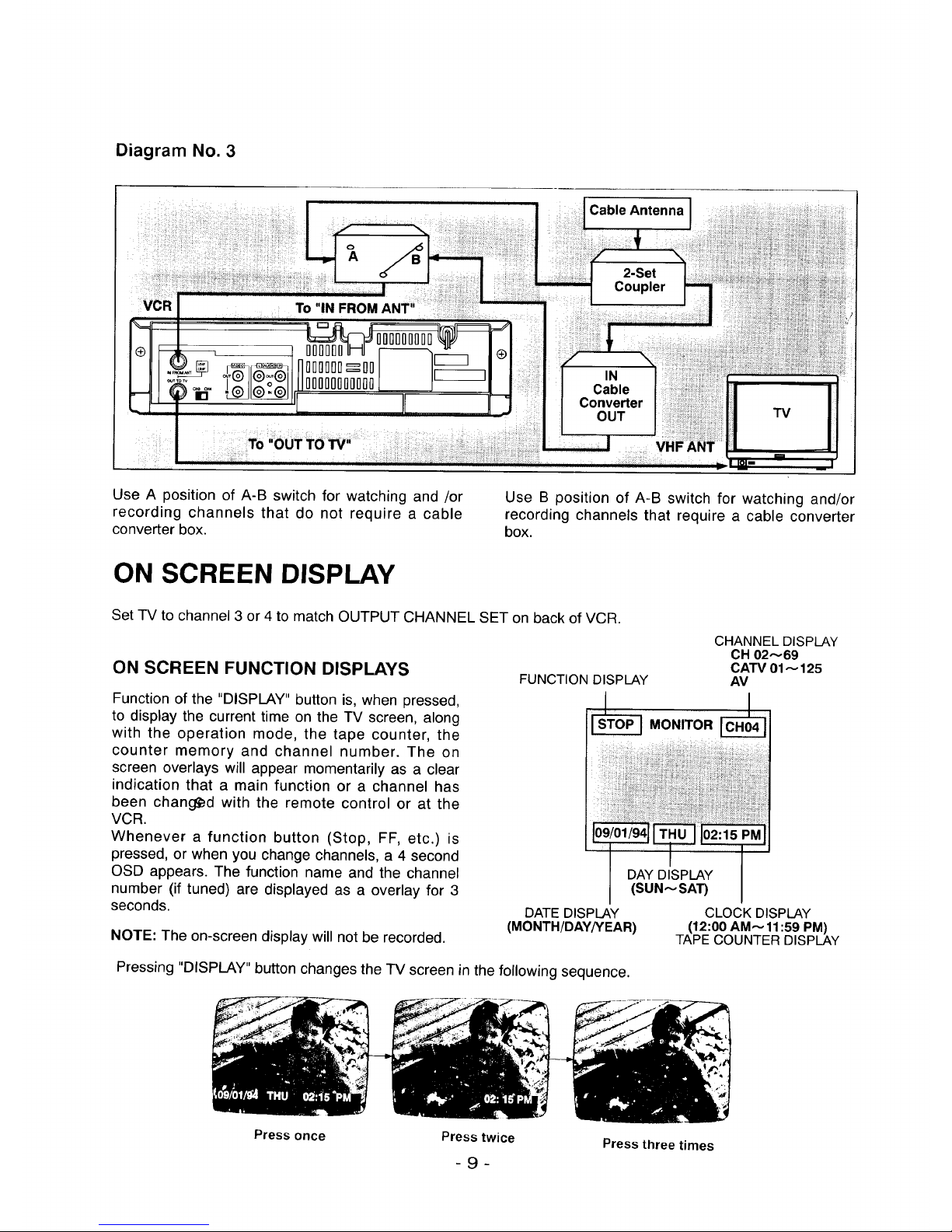
Diagram No. 3
Cable Antenna
To"IN FROM ANT"
IIIIIIIII
IIIII_II
"I
Cable
Converter
OUT
VHF ANT
Use A position of A-B switch for watching and /or
recording channels that do not require a cable
converter box.
Use B position of A-B switch for watching and/or
recording channels that require a cable converter
box.
ON SCREEN DISPLAY
Set TV to channel 3 or 4 to match OUTPUT CHANNEL SET on back of VCR.
ON SCREEN FUNCTION DISPLAYS
Function of the "DISPLAY" button is, when pressed,
to display the current time on the TV screen, along
with the operation mode, the tape counter, the
counter memory and channel number. The on
screen overlays will appear momentarily as a clear
indication that a main function or a channel has
been changed with the remote control or at the
VCR.
Whenever a function button (Stop, FF, etc.) is
pressed, or when you change channels, a 4 second
OSD appears. The function name and the channel
number (if tuned) are displayed as a overlay for 3
seconds.
NOTE: The on-screen display will not be recorded.
CHANNEL DISPLAY
CH 02_69
CATV01_ 125
FUNCTION DISPLAY AV
DAY DISPLAY
(SUN_SA'r)
DATE DISPLAY
(MONTH/DAY/YEAR)
CLOCK DISPLAY
(12:00 AM_11:59 PM)
TAPE COUNTER DISPLAY
Pressing "DISPLAY" button changes the TV screen in the following sequence.
Press once
Presstwice
- 9 -
Press three times
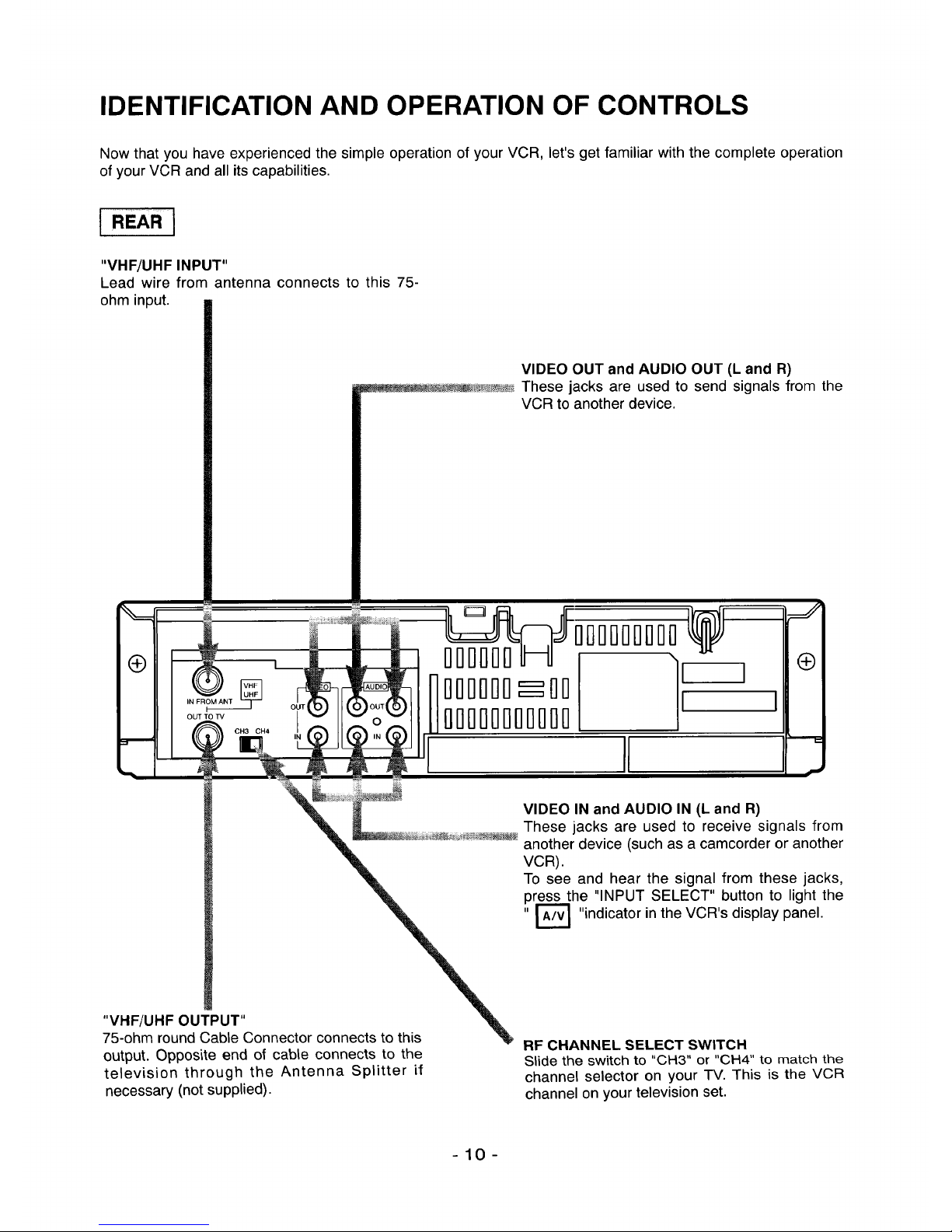
IDENTIFICATION AND OPERATION OF CONTROLS
Now that you have experienced the simple operation of your VCR, let's get familiar with the complete operation
of your VCR and all its capabilities.
I REAR ]
"VHF/UHF INPUT"
Lead wire from antenna connects to this 75-
ohm input.
®
VIDEO OUT and AUDIO OUT (L and R)
_ These jacks are used to send signals from the
VCR to another device.
IN FROM ANT T
=--
OUT TO IV
CH3 CH4
rlrlrlrlrll]
rlrlrlrlrlrl_rlrl
rlri0rlrlrlrlrl0rl0
i]i-trlllfli-ii]rl0
II
\
I I
J
®
€
VIDEO IN and AUDIO IN (L and R)
These jacks are used to receive signals from
another device (such as a camcorder or another
VCR).
To see and hear the signal from these jacks,
press the "INPUT SELECT" button to light the
"r'_ "indicator in the VCR's display panel.
"VHF/UHF OUTPUT"
75-ohm round Cable Connector connects to this
output. Opposite end of cable connects to the
television through the Antenna Splitter if
necessary (not supplied).
RF CHANNEL SELECT SWITCH
Slide the switch to "CH3" or "CH4" to match the
channel selector on your TV. This is the VCR
channel on your television set.
-10-
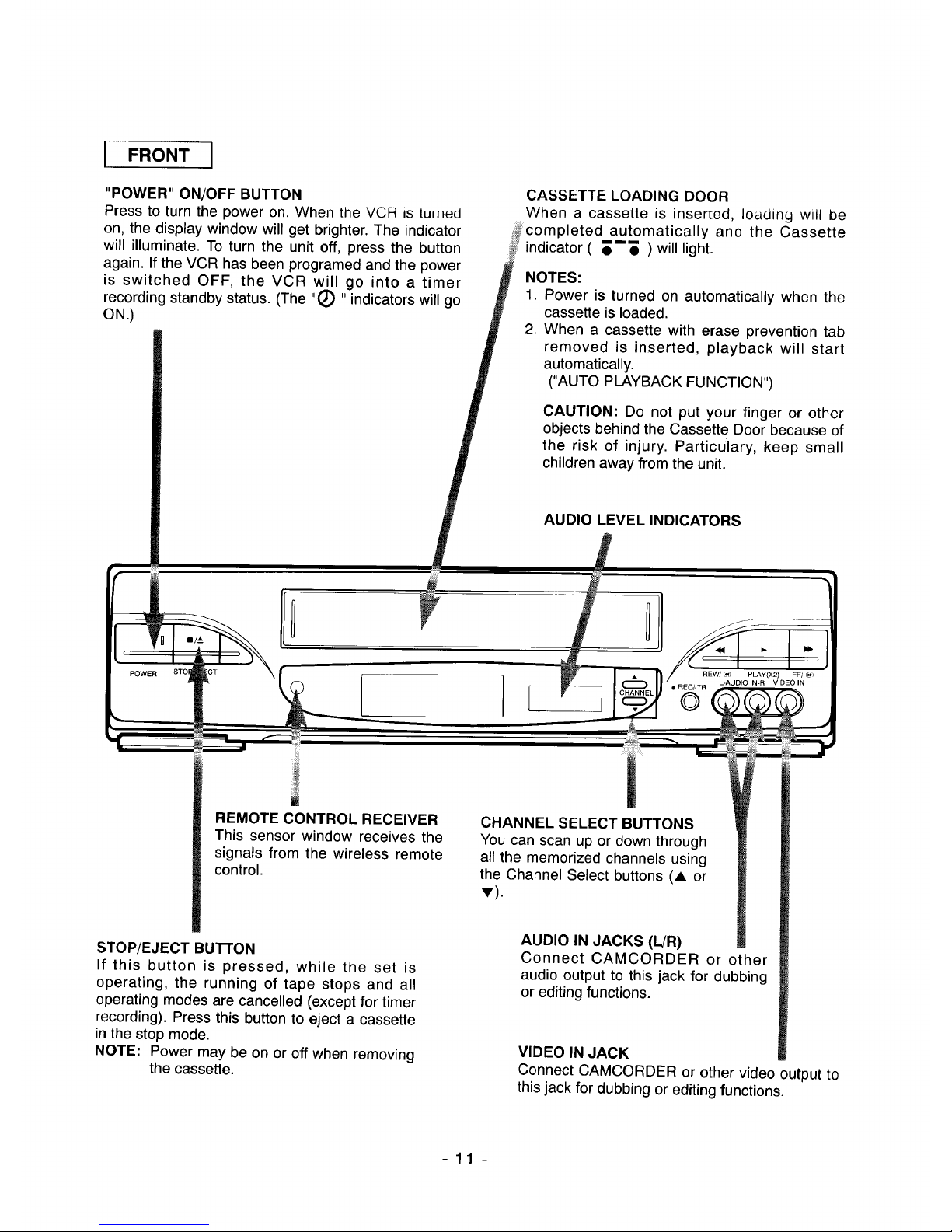
I FRONT 1
"POWER" ON/OFF BUTTON CASSETTE LOADING DOOR
Press to turn the power on. When the VCR is tun_ed When a cassette is inserted, loading will be
+_fcompleted automatically and the Cassette
'_+:_indicator ( _--_ ) will light.
on, the display window will get brighter. The indicator
will illuminate. To turn the unit off, press the button
again. If the VCR has been programed and the power
is switched OFF, the VCR will go into a timer
recording standby status. (The "(_ " indicators will go
ON.)
NOTES:
1. Power is turned on automatically when the
cassette is loaded.
2. When a cassette with erase prevention tab
removed is inserted, playback will start
automatically.
("AUTO PLAYBACK FUNCTION")
CAUTION: Do not put your finger or other
objects behind the Cassette Door because of
the risk of injury. Particulary, keep small
children away from the unit.
AUDIO LEVEL INDICATORS
POWER
REW/_J PLAY(X2) FF/ _,_
L-AUDIO IN-R VIDEO IN
REMOTE CONTROL RECEIVER
This sensor window receives the
signals from the wireless remote
control.
STOP/EJECT BUTTON
If this button is pressed, while the set is
operating, the running of tape stops and all
operating modes are cancelled (except for timer
recording). Press this button to eject a cassette
in the stop mode.
NOTE: Power may be on or off when removing
the cassette.
CHANNEL SELECT BUTTONS
You can scan up or down through
all the memorized channels using
the Channel Select buttons (A or
v).
AUDIO IN JACKS (L!R)
Connect CAMCORDER or other
audio output to this jack for dubbing
or editing functions.
VIDEO IN JACK
Connect CAMCORDER or other video output to
this jack for dubbing or editing functions.
-11 -
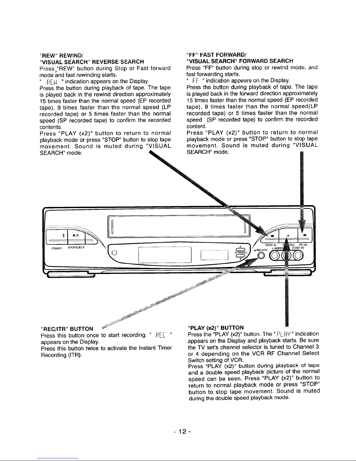
"REW" REWIND/
"VISUAL SEARCH" REVERSE SEARCH
Press_"REW" button during Stop or Fast forward
mode and fast rewinding starts.
li J I I II
_E-_ indication appears on the Display.
Press the button during playback of tape. The tape
is played back in the rewind direction approximately
15 times faster than the normal speed (EP recorded
tape), 9 times faster than the normal speed (LP
recorded tape) or 5 times faster than the normal
speed (SP recorded tape) to confirm the recorded
contents.
Press "PLAY (x2)" button to return to normal
playback mode or press "STOP" button to stop tape
movement. Sound is muted during "VISUAL
SEARCH" mode.
"FF" FAST FORWARD/
"VISUAL SEARCH" FORWARD SEARCH
Press "FF" button during stop or rewind mode, and
fast forwarding starts.
" F-F " indication appears on the Display.
Press the button during playback of tape. The tape
is played back in the forward direction approximately
15 times faster than the normal speed (EP recorded
tape), 9 times faster than the normal speed(LP
recorded tape) or 5 times faster than the normal
speed (SP recorded tape) to confirm the recorded
content.
Press "PLAY (x2)" button to return to normal
playback mode or press "STOP" button to stop tape
movement. Sound is muted during "VISUAL
SEARCH" mode.
POWER STOP/EJECT
...._ i_¸ •
"REC/ITR" BUTTON _#....
Press this button once to start recording. " PE_ "
appears on the Display.
Press this button twice to activate the Instant Timer
Recording (ITR).
"PLAY (x2)" BUTTON
Press the "PLAY (x2)" button. The "PL_£ _"indication
appears on the Display and playback starts. Be sure
the TV set's channel selector is tuned to Channel 3
or 4 depending on the VCR RF Channel Select
Switch setting of VCR.
Press "PLAY 0<2)" button during playback of tape
and a double speed playback picture of the normal
speed can be seen. Press "PLAY (x2)" button to
return to normal playback mode or press "STOP"
button to stop tape movement. Sound is muted
during the double speed playback mode.
-12-
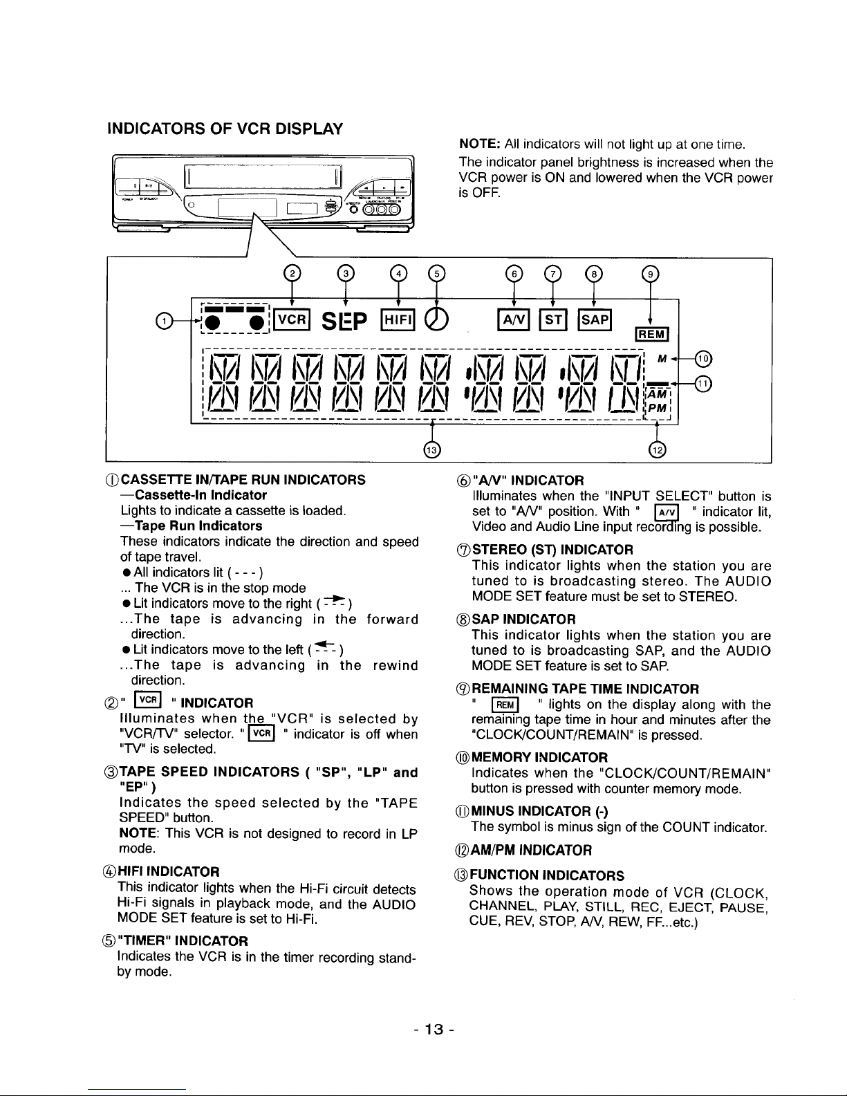
INDICATORS OF VCR DISPLAY
I il i-ii i
NOTE: All indicators will not light up at one time.
The indicator panel brightness is increased when the
VCR power is ON and lowered when the VCR power
is OFE
O- FNq
(_)CASSETTE IN/I'APE RUN INDICATORS
--Cassette-In Indicator
Lightsto indicate a cassette is loaded.
--Tape Run Indicators
These indicators indicate the direction and speed
of tape travel.
• All indicators lit ( - - - )
... The VCR is in the stop mode
• Lit indicators move to the right ( _ )
...The tape is advancing in the forward
direction.
• Lit indicators move to the left ( :'_---- )
...The tape is advancing in the rewind
direction.
®,, ,,INDICATOR
Illuminates when the "VCR" is selected by
"VCR/'I-V" selector. ,,r_ ,, indicator is off when
"IV" is selected.
(_TAPE SPEED INDICATORS ( "SP", "LP" and
"EP" )
Indicates the speed selected by the "TAPE
SPEED" button.
NOTE: This VCR is not designed to record in LP
mode.
(_)HIFI INDICATOR
This indicator lights when the Hi-Fi circuit detects
Hi-Fi signals in playback mode, and the AUDIO
MODE SET feature is set to Hi-Fi.
"TIMER" INDICATOR
Indicates the VCR is in the timer recording stand-
by mode.
@ "A/V" INDICATOR
Illuminates when the "INPUT SELECT" button is
set to "A/V" position. With " r_ " indicator lit,
Video and Audio Line input recor----'_ngis possible.
@STEREO (ST) INDICATOR
This indicator lights when the station you are
tuned to is broadcasting stereo. The AUDIO
MODE SET feature must be set to STEREO.
(_)SAP INDICATOR
This indicator lights when the station you are
tuned to is broadcasting SAP, and the AUDIO
MODE SET feature is set to SAP.
(_)REMAINING TAPE TIME INDICATOR
" _ " lights on the display along with the
remaining tape time in hour and minutes after the
"CLOCK/COUNT/REMAIN" is pressed.
_) MEMORY INDICATOR
Indicates when the "CLOCK/COUNT/REMAIN"
button ispressed with counter memory mode.
@ MINUS INDICATOR (-)
The symbol is minus sign of the COUNT indicator,
@AM/PM INDICATOR
(_)FUNCTION INDICATORS
Shows the operation mode of VCR (CLOCK,
CHANNEL, PLAY, STILL, REC, EJECT, PAUSE,
CUE, REV, STOP, AN, REW, FF...etc.)
-13-
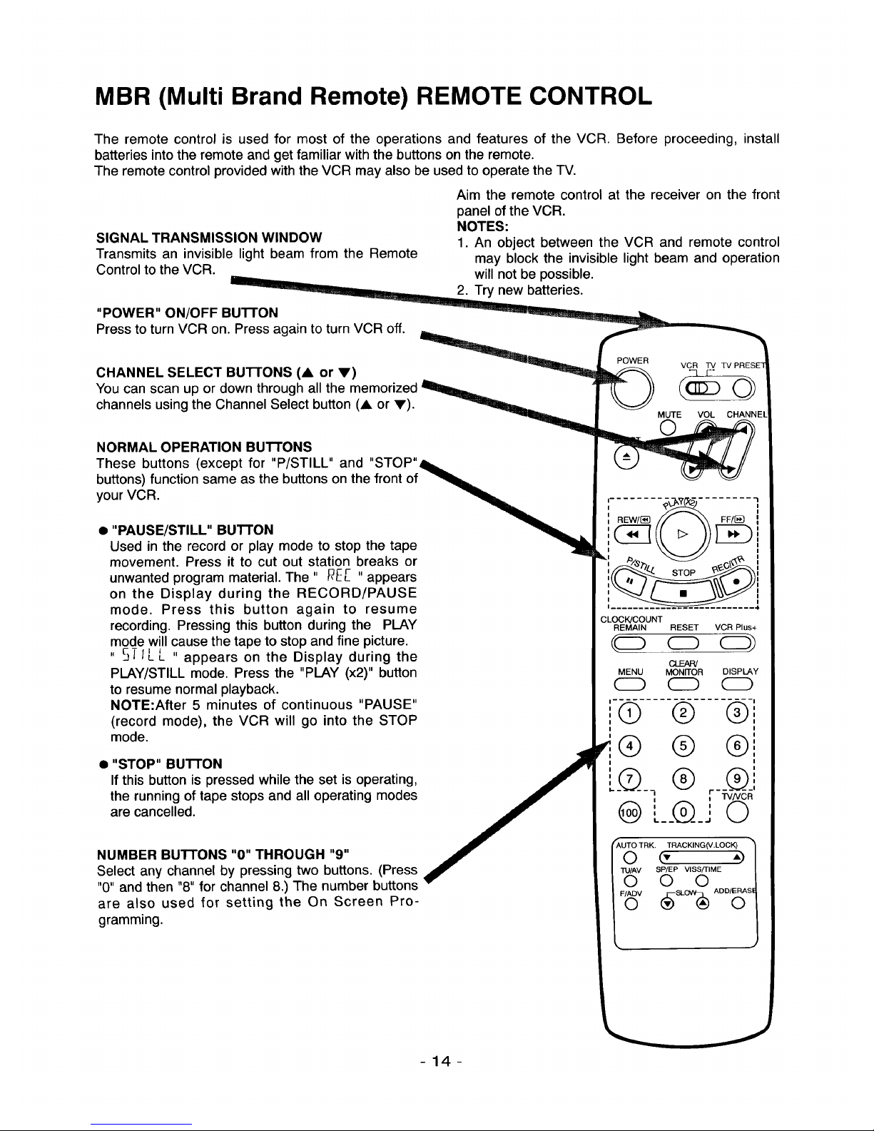
MBR (Multi Brand Remote) REMOTE CONTROL
The remote control is used for most of the operations and features of the VCR. Before proceeding, install
batteries into the remote and get familiar with the buttons on the remote.
The remote control provided with the VCR may also be used to operate the TV.
SIGNAL TRANSMISSION WINDOW
Transmits an invisible light beam from the Remote
Control to the VCR.
"POWER" ON/OFF Bu'n'ON
Press to turn VCR on. Press again to turn VCR off.
Aim the remote control at the receiver on the front
panel of the VCR.
NOTES:
1. An object between the VCR and remote control
may block the invisible light beam and operation
will not be possible.
2. Try new batteries.
CHANNEL SELECT BU'I-rONS (A or V)
You can scan up or down through all the
channels usingthe Channel Select button (A or V).
POWER
VCR TV TV PRESE
(aSo)
MUTE VOL CHANNEl
NORMAL OPERATION Bu'PrONS
These buttons (except for "P/STILL" and "STOP"_
buttons) function same as the buttons on the front of _=.=
your VCR. ,, _b_
• PAUSE/STILL BUTTON _,.
Used in the record or play mode to stop the tape _J_
movement. Press it to cut out station breaks or
unwanted program material. The " _E[ " appears
on the Display during the RECORD/PAUSE
mode. Press this button again to resume
recording. Pressing this button during the PLAY
mode will cause the tape to stop and fine picture.
" 5TIE L " appears on the Display during the
PLAY/STILL mode. Press the "PLAY (x2)" button
to resume normal playback.
NOTE:After 5 minutes of continuous "PAUSE"
(record mode), the VCR will go into the STOP
mode.
• "STOP" BUTTON
If this button is pressed while the set is operating,
the running of tape stops and all operating modes
are cancelled.
NUMBER Bu'n'ONS "0" THROUGH "9"
Select any channel by pressing two buttons. (Press
"0" and then "8" for channel 8.) The number buttons
are also used for setting the On Screen Pro-
gramming.
STOP
I. 4
CLOCK/COUNT
REMAIN RESET VCR Plus+
CD CD)
CLEAR/
MENU MONITOR DISPLAY
(_) CD (_)
C) (_-
I I
I
I I
@
TV/VCR
@ L__@0_.
(AUTO TRK, TRACKING(V.LOCK)
O (,' ")
"nJ/AV SP/EP VlSS/TIME
O O O
-14-
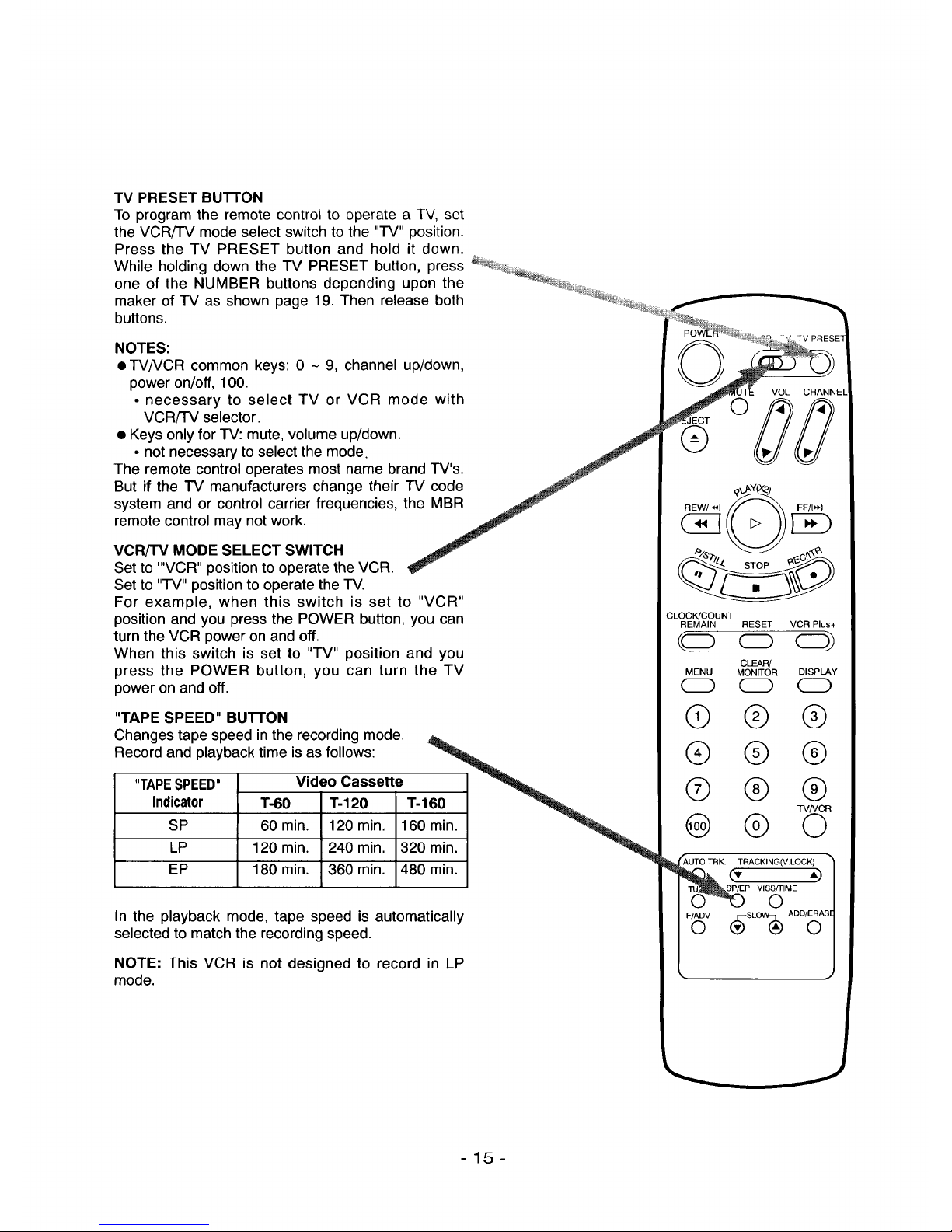
TVPRESETBUTTON
ToprogramtheremotecontroltooperateaTV,set
theVCR/TVmodeselectswitchtothe"TV"position.
Pressthe TV PRESETbuttonand holdit down.
WhileholdingdowntheTVPRESETbutton,press
oneof theNUMBERbuttonsdependinguponthe
makerofTVasshownpage19.Thenreleaseboth
buttons.
NOTES:
• TV/VCR common keys: 0 - 9, channel up/down,
power on/off, 100.
• necessary to select TV or VCR mode with
VCR/TV selector.
• Keys only for TV: mute, volume up/down.
• not necessary to select the mode.
The remote control operates most name brand TV's.
But if the TV manufacturers change their "FV code
system and or control carrier frequencies, the MBR
remote control may not work.
VCR/TV MODE SELECT SWITCH
Set to '"VCR" position to operate the VCR.
Set to "TV" position to operate the TV.
For example, when this switch is set to "VCR"
position and you press the POWER button, you can
turn the VCR power on and off.
When this switch is set to "TV" position and you
press the POWER button, you can turn the TV
power on and off.
"TAPE SPEED" BUTTON
Changes tape speed in the recording mode.
Record and playback time is as follows:
TAPESPEED Video Cassette _,,_
Indicator "1"-60 T-120 T-160 ""q_.
SP 60 min. 120 min. 160 min. _._,_
LP 120 min. 240 min. 320 rain. _"_ql!
EP 180 min. 360 min. 480 rain.
In the playback mode, tape speed is automatically
selected to match the recording speed.
NOTE: This VCR is not designed to record in LP
mode.
VOL CHANNEL
o00
®
CLOCK/COUNT
REMAIN RESET VCR Plus+
(o o CD)
MENU
CLEAR/
MONITOR DISPLAY
0 0
® ® ®
® ® ®
® @ @
TVNCR
@ ® O
_,UTO TRK. TRACKING(V.LOCK) •
-15-
CLOCK!COUNT
REMAIN RESET VCR Plus+
((:::3 (z)
MENU MONITOR DISPLAY
CD
@ @ @
® @ @
@ @
_,UTO TRK. TRACKING(V.LOCK)
0 (- ")
"ilJ/AV SP/EP VISS/TIME
0 0 0
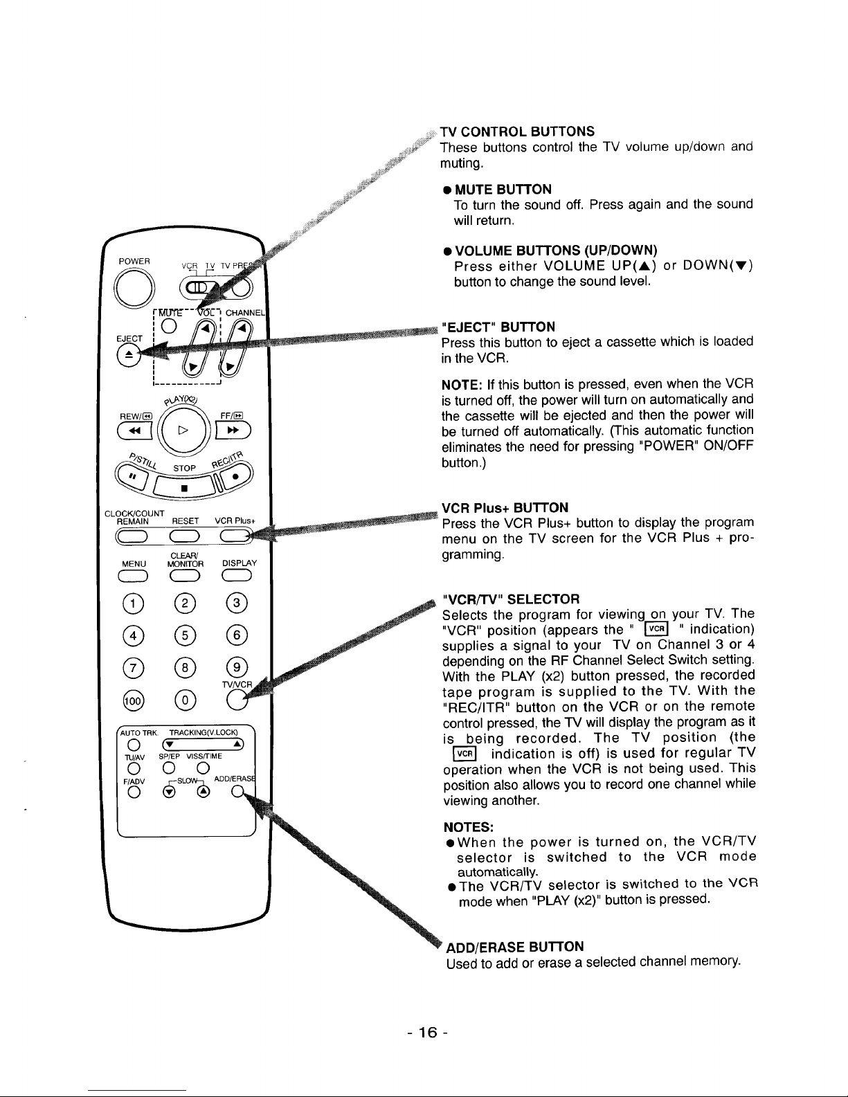
TV CONTROL BUTTONS
These buttons control the TV volume up/down and
......S__'¸
] ....
f,,
muting.
• MUTE BUTTON
To turn the sound off. Press again and the sound
will return.
• VOLUME BUTTONS (UP/DOWN)
Press either VOLUME UP(A) or DOWN(V)
button to change the sound level.
=_m___ "EJECT" BUTTON
Press this button to eject a cassette which is loaded
in the VCR.
NOTE: If this button is pressed, even when the VCR
is turned off, the power will turn on automatically and
the cassette will be ejected and then the power will
be turned off automatically. (This automatic function
eliminates the need for pressing "POWER" ON/OFF
button .)
VCR Plus+ BUTTON
Press the VCR Plus+ button to display the program
menu on the TV screen for the VCR Plus + pro-
gramming.
"VCRiTV" SELECTOR
Selects the program for viewing on your TV. The
"VCR" position (appears the " r_ ,, indication)
supplies a signal to your TV on Channel 3 or 4
depending on the RF Channel Select Switch setting.
With the PLAY (x2) button pressed, the recorded
tape program is supplied to the TV. With the
"REC/ITR" button on the VCR or on the remote
control pressed, the TV will display the program as it
is being recorded. The TV position (the
r_ indication is off) is used for regular TV
operation when the VCR is not being used. This
position also allows you to record one channel while
viewing another.
NOTES:
• When the power is turned on, the VCR/TV
selector is switched to the VCR mode
automatically.
• The VCR/TV selector is switched to the VCR
mode when "PLAY (x2)" button is pressed.
ADD/ERASE BUTTON
Used to add or erase a selected channel memory.
-16-
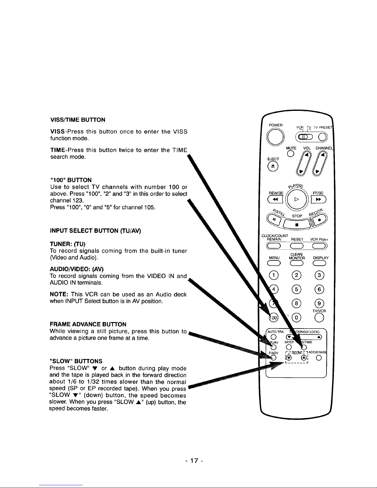
VISS/TIME BUTTON
VISS-Press this button once to enter the VISS
function mode.
TIME-Press this button twice to enter the TIME
search mode.
"100" BU'B'ON
Use to select TV channels with number 100 or
above. Press "100", "2" and "3" in this order to select
channel 123.
Press "100", "0" and "5" for channel 105.
INPUT SELECT BUTTON (TU/AV)
TUNER: (TU)
To record signals coming from the built-in tuner
(Video and Audio).
AUDIO/VIDEO: (AV)
To record signals coming from the VIDEO IN and
AUDIO IN terminals.
NOTE: This VCR can be used as an Audio deck
when INPUT Select button is inAV position.
FRAME ADVANCE BUTTON
While viewing a still picture, press this button to
advance a picture one frame at a time.
"SLOW" BUTTONS
Press "SLOW" • or • button during play mode
and the tape is played back in the forward direction
about 1/6 to 1/32 times slower than the normal
speed (SP or EP recorded tape). When you press
"SLOW •" (down) button, the speed becomes
slower. When you press "SLOW •" (up) button, the
speed becomes faster.
POWER
VCR TV TV PRESE
O
MUTE VOL CHANNEl
o00
®
CLOCK!COUNT
REMAIN RESET VCR Plus+
(c:> _)
CLEAR!
MENU MON_OR DISP_Y
CD
® ® ®
® ®
® ®
TV/VCR
® O
-17-
POWER
VCR TV TVPRESET
0
o)
MUTE VOL CHANNEt
©
EJECT
®
C!
CLEAR!
MENU MONITOR
CC) O
® ®
® ®
® ®
@ ®
DISPLAY ',
(ZD',
!
®
®
®
TVNCR
O
r_L_TO'TR_:- _W_-oc_ - -_
- -8_'- ¥18_r-tME- - - - J
© © ©
s,
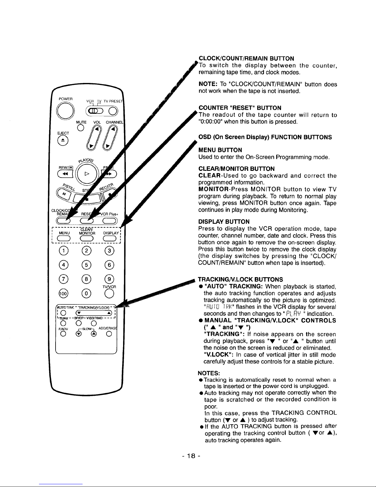
CLOCK!COUNT/REMAIN BUTTON
switch the display between the counter,
remaining tape time, and clock modes.
NOTE: To "CLOCK/COUNT/REMAIN" button does
not work when the tape is not inserted.
COUNTER "RESET" BU'B'ON
readout of the tape counter will return to
"0:00:00" when this button is pressed.
OSD (On Screen Display) FUNCTION BuTroNs
MENU BUTTON
Used to enter the On-Screen Programming mode.
CLEAR/MONITOR BU'B'ON
CLEAR-Used to go backward and correct the
programmed information.
MONITOR-Press MONITOR button to view TV
program during playback. To return to normal play
viewing, press MONITOR button once again. Tape
continues in play mode during Monitoring.
DISPLAY BU'PFON
Press to display the VCR operation mode, tape
counter, channel number, date and clock. Press this
button once again to remove the on-screen display.
Press this button twice to remove the clock display
(the display switches by pressing the "CLOCK/
COUNT/REMAIN" button when tape is inserted).
TRACKING/V.LOCK BUTTONS
• "AUTO" TRACKING: When playback is started,
the auto tracking function operates and adjusts
tracking automatically so the picture is optimized.
EuTu Tg_" flashes in the VCR display for several
seconds and then changes to "PL )qY" indication.
• MANUAL "TRACKING/V.LOCK" CONTROLS
(11 • II and liT, I1)
"TRACKING": If noise appears on the screen
during playback, press "V " or "A " button until
the noise on the screen is reduced or eliminated.
"V.LOCK": In case of vertical jitter in still mode
carefully adjust these controlsfor a stable picture.
NOTES:
• Tracking is automatically reset to normal when a
tape is inserted or the power cord is unplugged.
• Auto tracking may not operate correctly when the
tape is scratched or the recorded condition is
poor.
In this case, press the TRACKING CONTROL
button (V or • ) to adjust tracking.
• If the AUTO TRACKING button is pressed after
operating the tracking control button ( Vor •),
auto tracking operates again.
-18-
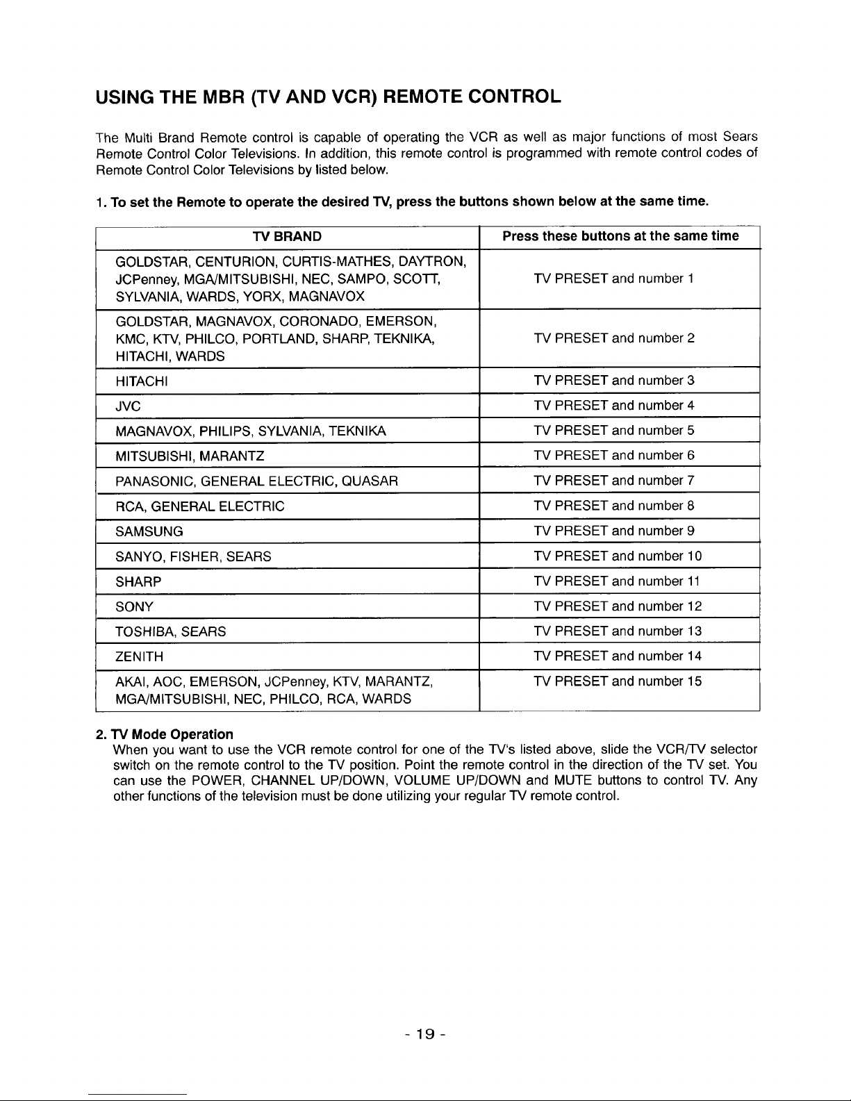
USING THE MBR (TV AND VCR) REMOTE CONTROL
The Multi Brand Remote control is capable of operating the VCR as well as major functions of most Sears
Remote Control Color Televisions. In addition, this remote control is programmed with remote control codes of
Remote Control Color Televisions by listed below.
1. To set the Remote to operate the desired "IV, press the buttons shown below at the same time.
TV BRAND Press these buttons at the same time
GOLDSTAR, CENTURION, CURTIS-MATHES, DAYTRON,
JCPenney, MGA/MITSUBISHI, NEC, SAMPO, SCOTT, IV PRESET and number 1
SYLVANIA, WARDS, YORX, MAGNAVOX
GOLDSTAR, MAGNAVOX, CORONADO, EMERSON,
KMC, KTV, PHILCO, PORTLAND, SHARP, TEKNIKA, IV PRESET and number 2
HITACHI, WARDS
HITACHI TV PRESET and number 3
JVC IV PRESET and number 4
MAGNAVOX, PHILIPS, SYLVANIA, TEKNIKA TV PRESET and number 5
MITSUBISHI, MARANTZ TV PRESET and number 6
PANASONIC, GENERAL ELECTRIC, QUASAR TV PRESET and number 7
RCA, GENERAL ELECTRIC TV PRESET and number 8
SAMSUNG TV PRESET and number 9
SANYO, FISHER, SEARS TV PRESET and number 10
SHARP TV PRESET and number 11
SONY TV PRESET and number 12
TOSHIBA, SEARS TV PRESET and number 13
ZENITH -IV PRESET and number 14
AKAI, AOC, EMERSON, JCPenney, KTV, MARANTZ, TV PRESET and number 15
MGA/MITSUBISHI, NEC, PHILCO, RCA, WARDS
2. TV Mode Operation
When you want to use the VCR remote control for one of the TV's listed above, slide the VCR/TV selector
switch on the remote control to the TV position. Point the remote control in the direction of the IV set. You
can use the POWER, CHANNEL UP/DOWN, VOLUME UP/DOWN and MUTE buttons to control TV. Any
other functions of the television must be done utilizing your regular TV remote control.
-19-
SET YOUR TELEVISION TO THE VCR CHANNEL
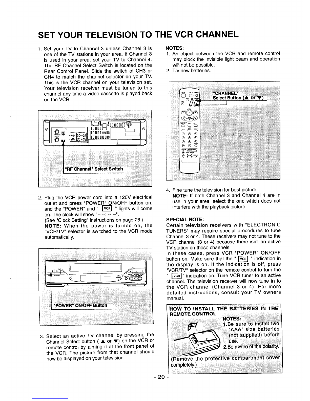
1. Set your TV to Channel 3 unless Channel 3 is
one of the TV stations in your area. If Channel 3
is used in your area, set your TV to Channel 4.
The RF Channel Select Switch is located on the
Rear Control Panel. Slide the switch of CH3 or
CH4 to match the channel selector on your TV.
This is the VCR channel on your television set.
Your television receiver must be tuned to this
channel any time a video cassette is played back
on the VCR.
NOTES:
1. An object between the VCR and remote control
may block the invisible light beam and operation
will not be possible.
2. Try new batteries.
_ i_i_i_ii_iiiiii_i_!_i_i_'i_i!_iii?_ili__!_!_iji __,_i,i_i_i_iii_i_Di_,,ii!_!_i_;_i_i:ii_,_i:_i_ii_,%:i_iii_i_i_i_ii_i_i!i_i!_i_!_!i_i_i_ii!i_iiii!_i,!iii_i!__i_!_i_i_i!_;iiI
iiiiiiiiiiiiliiiiiiiliiiiiiiiiiiiiiiiiiiiii!iiiiii i
"RF _hannei;i Seie¢_ itch
2. Plug the VCR power cord into a 120V electrical
outlet and press "POWER" ON/OFF button on,
and the "POWER" and " [_ " lights will come
on. The clock will show .....
(See "Clock Setting" Instructions on page 28.)
NOTE: When the power is turned on, the
"VCR/TV" selector is switched to the VCR mode
automatically.
4. Fine tune the television for best picture.
NOTE: If both Channel 3 and Channel 4 are in
use in your area, select the one which does not
interfere with the playback picture.
SPECIAL NOTE:
Certain television receivers with "ELECTRONIC
TUNERS" may require special procedures to tune
Channel 3 or 4. These receivers may not tune to the
VCR channel (3 or 4) because there isn't an active
-IV station on these channels.
In these cases, press VCR "POWER" ON/OFF
button on. Make sure that the " _ " indication in
the display is on. If the indication is off, press
"VCR/'I-V" selector on the remote control to turn the
" _" indication on. Tune VCR tuner to an active
channel. The television receiver will now tune in to
the VCR channel (Channel 3 or 4). For more
detailed instructions, consult your TV owners
manual.
3. Select an active TV channel by pressing the
Channel Select button ( • or V) on the VCR or
remote control by aiming it at the front panel of
the VCR. The picture from that channel should
now be displayed on your television.
REMOTE CONTROL
- 20 -
 Loading...