

Sears LXI series 580.53425390,LXI series 580.53425390 Owner's Manual
|IIII|
tl ll
OWNERS
MANUAL
MODEL NO.
580.53425390
KNOW YOUR UNIT
Read this booklet so you will be
able toenjoyall the features in your
video cassette recorder.
Record in space provided below
the Model No. and the Serial No.
as found on the rear of your video
cassette recorder.
Model No.
Serial No.
Retain this information for future
reference.
.o q_L6l
0®01
®o® I
: 0®® I
+ +6 I
I
E
IPtSTILL IbR£C'Im
--?@@
ID F'_
l P"
VIDEO CASSETTE
RECORDER
Operation
Sears, Roebuck and Co., Hoffman Estates, IL. 60179. U.S.A.
WARNING: TO PREVENT FIRE OR SHOCK HAZARD, DO NOT
EXPOSE THIS APPLIANCE TO RAIN OR MOISTURE.
RISK OF ELECTRIC SHOCK
DO NOT OPEN
CAUTION: TO REDUCE THE RISK OF ELECTRIC SHOCK.
DO NOT REMOVE COVER (OR BACK).
NO USER-SERVICEABLE PARTS INSIDE.
REFER SERVICING TO QUALIFIED SERVICE
PERSONNEL.
The exclamation point within an equilateral triangle
is intended to alert the user to the presence of
important operating and maintenance (servicing)
instructions in the literature accompanying the
product.
The lightning flash with arrowhead symbol, within
an equilateral triangle, is intended to alert the user
to the presence of uninsulated "dangerous
voltage" within the product's enclosure that may be
of sufficient magnitude to constitute a risk of
electric shock to persons.
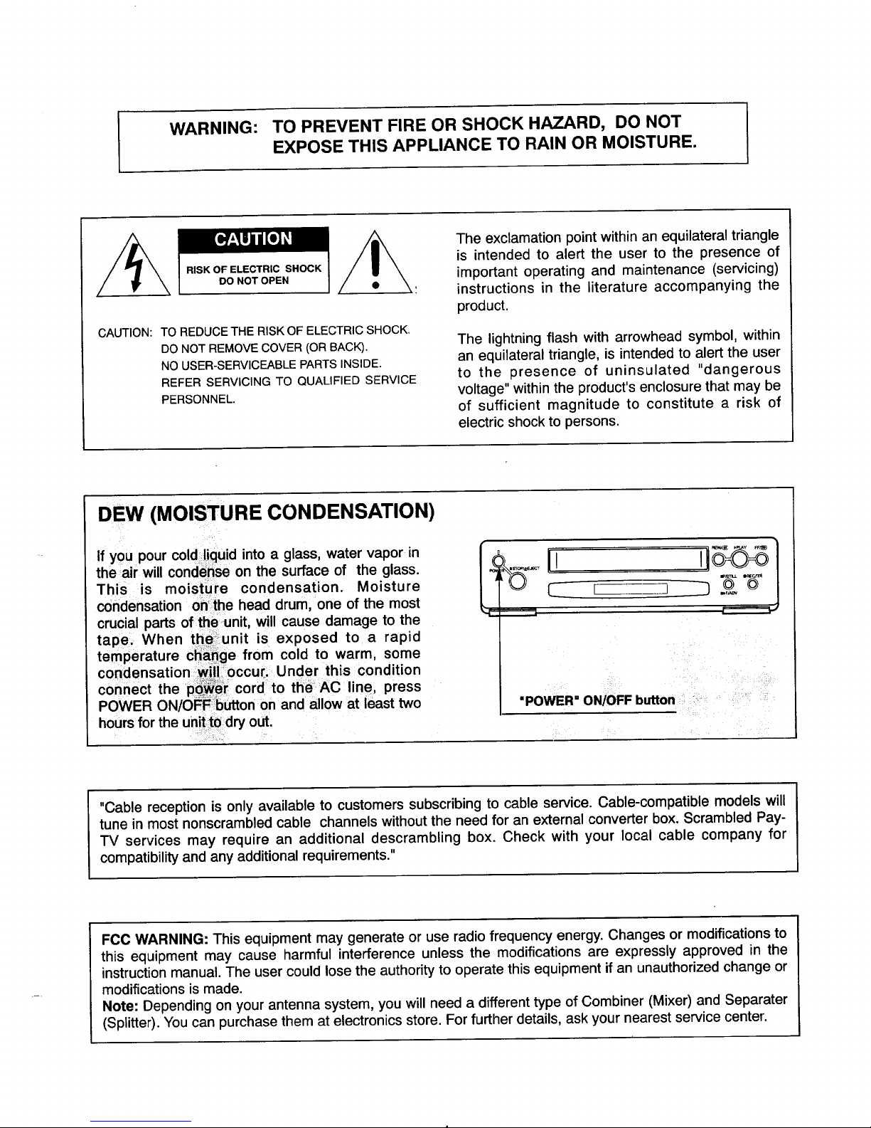
DEW (MOISTURE CONDENSATION)
If you pour cold liquid into a glass, water vapor in
the air will condense on the surface of the glass.
This is moisture condensation. Moisture
condensation onthe head drum, one of the most
crucial parts of the unit, will cause damage to the
tapei: When thai.unit is exposed to a rapid
temperature cha_ge from cold to warm, some
condensation wili occur; Under this condition
connect the p cord to th_ AC line, press
POWER ON/OFF button on and allow at least two
hours for the unit to dry out.
I MY
_LL O_rJl_
r=,=,,--=_
_i,: : _!i!i_!ii_ili!ilil
ii_ : • _i i
WER"ON/OFF button
"Cable reception is only available to customers subscribing to cable service. Cable-compatible models will
tune in most nonscrambled cable channels without the need for an external converter box. Scrambled Pay-
TV services may require an additional descrambling box. Check with your local cable company for
compatibility and any additional requirements."
FCC WARNING: This equipment may generate or use radio frequency energy. Changes or modifications to
this equipment may cause harmful interference unless the modifications are expressly approved in the
instruction manual. The user could lose the authority to operate this equipment if an unauthorized change or
modifications is made.
Note: Depending on your antenna system, you will need a different type of Combiner (Mixer) and Separater
(Splitter). You can purchase them at electronics store. For further details, ask your nearest service center.
Congratulationson buying the _ Video Cassette Recorder (VCR). For your convenience, please read
these simple instructions before operating your VCR.
NOTES: * This Video Cassette Recorder is compatibte with any video cassette bearing the _ mark.
• _ is designed to expand your opportunities for in-home TV viewing and not for any usage
which might violate the copyright laws.
. The Video Cassette Recorder (VCR) with this marking incorporates _ high-quality
picture technology and is compatible any
with
Video Cassette
Recorders
bearing
the _ mark.
Check to make sure you have the following
accessories before disposing of the packing
material.
1. 75-ohm Coaxial Cable with Antenna Adaptor
(75/300-ohm)
2. Remote Control
TABLE OF CONTENTS
Important Safety Instructions .............. 3
Installation ............................. 5
Wiring diagram .......................... 5
AntennaNCR connections ................. 6
VCR/'FV connections ..................... 7
Cable antenna (CATV) connections .......... 8
On Screen Display ....................... 9
On Screen Menu features ................. 10
Channel presetting
(By using the remote control) ............. 11
Set your television to the VCR channel ...... 13
Making a sample recording ............... 14
Identification and operation of controls ..... 15
Remote Control ........................ 19
Clock setting (By using the remote control)..22
Recording while you are away ............. 24
Program timer setting
(You must use the remote control) ......... 25
Instant Timer Recording (ITR) ............. 30
Recording one program while viewing
Another ................................ 31
Editing a recording ...................... 31
VHS Index search system (VlSS) ........... 32
Visual search (F-Search and R-Search) ...... 33
Pause/Still ............................. 34
Frame advance ......................... 34
Slow ................................. 34
Auto playback function .................. 35
Using the counter memory feature ......... 35
Auto-rewind ........................... 36
Auto memory power shut-off .............. 36
Playback with TV equipped with VIR ........ 36
Video Head Cleaning .................... 36
Operating hints ......................... 37
VCR to VCR dubbing .................... 37
Troubleshooting ........................ 38
Routine maintenance .................... 39
Sears Service .......................... 39
How to order repair parts ................. 39
Specifications .......................... 40
Features .............................. 40
Warranty ....................... Rear Cover
IMPORTANT SAFETY INSTRUCTIONS
=
.
=
.
5.
°
=
.
.
Read Instructions-All the safety and
operating instructions should be read before
the product is operated.
Retain Instructions-The safety and operating
instructions should be retained for future
reference.
Heed Warnings-All warnings on the product
and in the operating instructions should be
adhered to.
Follow Instructions-All operating and use
instructions should be followed.
Cleaning-Unplug this product from the wall
outlet before cleaning. Do not use liquid
cleaners or aerosol cleaners. Use a damp
cloth for cleaning.
Exception: A product that is meant for
uninterrupted service and that for some
specific reason, such as the possibility of the
loss of an authorization code for a CATV
converter, is not intended to be unplugged by
the user for cleaning or any other purpose,
may exclude the reference to unplugging the
product in the cleaning description otherwise
required in item 5.
Attachments-Do not use attachments not
recommended by the product manufacturer as
they may cause hazards.
Water and Moisture-Do not use this product
near water- for example, near a bath tub,
wash bowl, kitchen sink, or laundry tub; in a
wet basement; or near a swimming pool; and
the like.
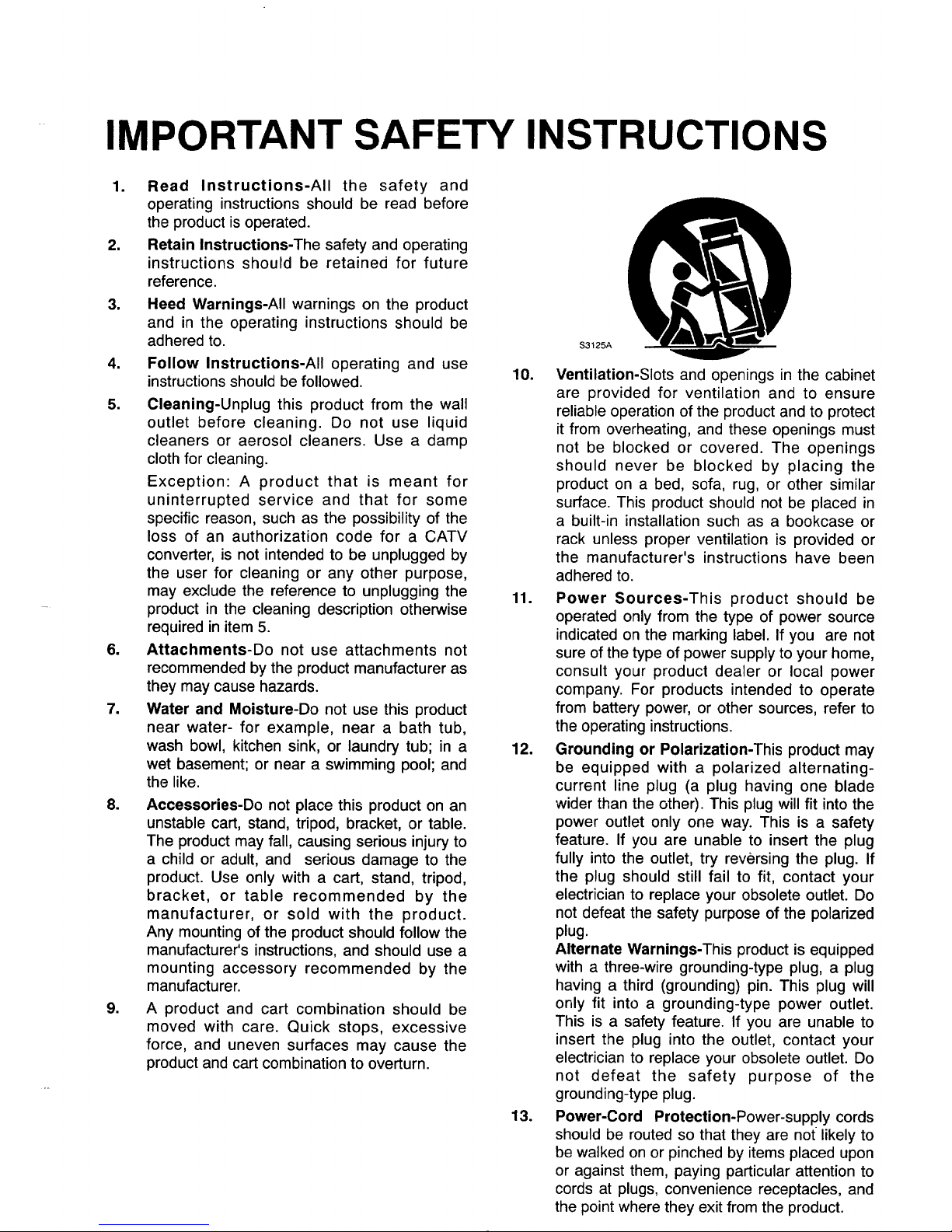
Accessories-Do not place this product on an
unstable cart, stand, tripod, bracket, or table.
The product may fall, causing serious injury to
a child or adult, and serious damage to the
product. Use only with a cart, stand, tripod,
bracket, or table recommended by the
manufacturer, or sold with the product.
Any mounting of the product should follow the
manufacturer's instructions, and should use a
mounting accessory recommended by the
manufacturer.
A product and cart combination should be
moved with care. Quick stops, excessive
force, and uneven surfaces may cause the
product and cart combination to overturn.
$3125A
10. Ventilation-Slots and openings in the cabinet
are provided for ventilation and to ensure
reliable operation of the product and to protect
it from overheating, and these openings must
not be blocked or covered. The openings
should never be blocked by placing the
product on a bed, sofa, rug, or other similar
surface. This product should not be placed in
a built-in installation such as a bookcase or
rack unless proper ventilation is provided or
the manufacturer's instructions have been
adhered to.
11. Power Sources-This product should be
operated only from the type of power source
indicated on the marking label. If you are not
sure of the type of power supply to your home,
consult your product dealer or local power
company. For products intended to operate
from battery power, or other sources, refer to
the operating instructions.
12. Grounding or Polarization-This product may
be equipped with a polarized alternating-
current line plug (a plug having one blade
wider than the other). This plug will fit into the
power outlet only one way. This is a safety
feature. If you are unable to insert the plug
fully into the outlet, try reversing the plug. If
the plug should still fail to fit, contact your
electrician to replace your obsolete outlet. Do
not defeat the safety purpose of the polarized
plug.
Alternate Warnings-This product is equipped
with a three-wire grounding-type plug, a plug
having a third (grounding) pin. This plug will
only fit into a grounding-type power outlet.
This is a safety feature. If you are unable to
insert the plug into the outlet, contact your
electrician to replace your obsolete outlet. Do
not defeat the safety purpose of the
grounding-type plug.
13. Power-Cord Protection-Power-supply cords
should be routed so that they are not likely to
be walked on or pinched by items placed upon
or against them, paying particular attention to
cords at plugs, convenience receptacles, and
the point where they exit from the product.
14.
15.
Protective Attachment Plug-The product is
equipped with an attachment plug having
overload protection. This is a safety feature.
See Instruction. Manual for replacement or
resetting of protective device. If replacement
of the plug is required, be sure the service
technician has used a replacement plug
specified by the manufacturer that has the
same overload protection as the original plug.
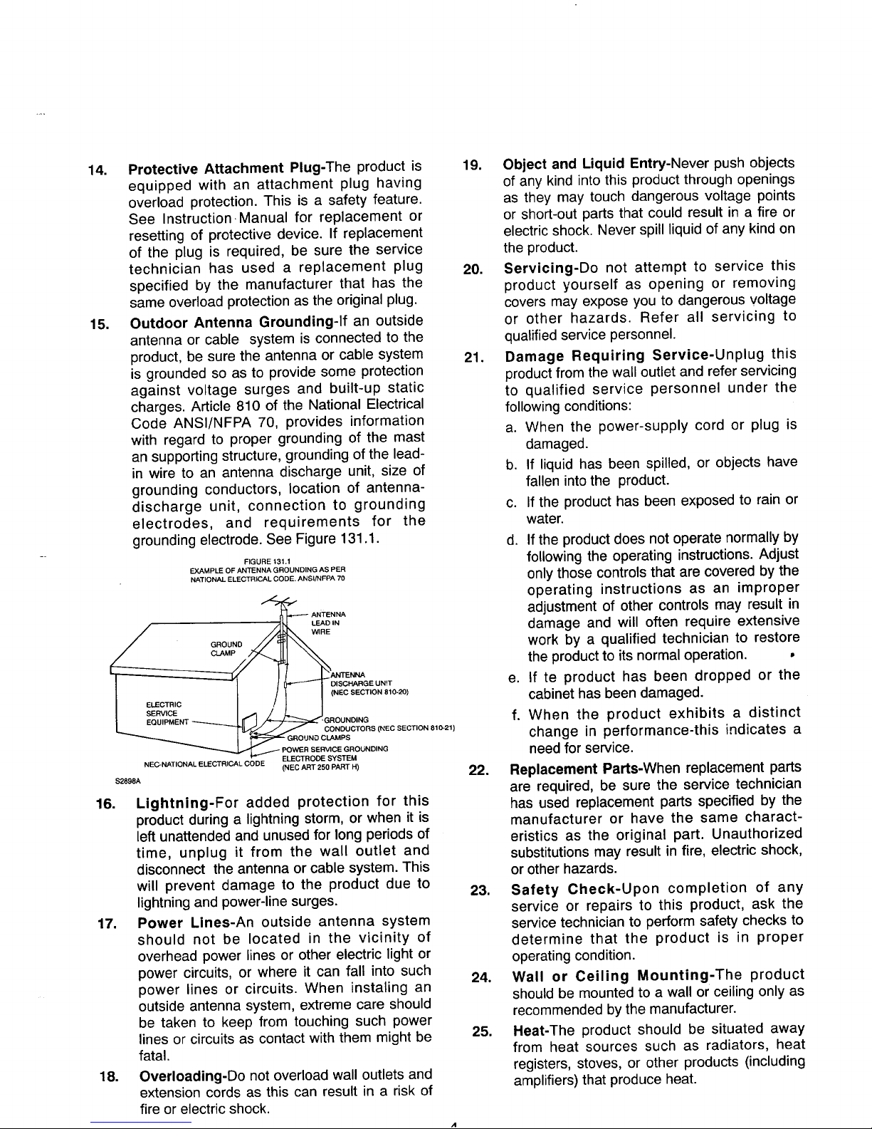
Outdoor Antenna Grounding-If an outside
antenna or cable system is connected to the
product, be sure the antenna or cable system
is grounded so as to provide some protection
against voltage surges and built-up static
charges. Article 810 of the National Electrical
Code ANSI/NFPA 70, provides information
with regard to proper grounding of the mast
an supportingstructure, grounding ofthe lead-
in wire to an antenna discharge unit, size of
grounding conductors, location of antenna-
discharge unit, connection to grounding
electrodes, and requirements for the
grounding electrode. See Figure 131.1.
FIGURE 131.1
EXAMPLE OF ANTENNA GROUNDING AS PER
NATIONAL ELECTRICAL CODE. AN SI/NFPA 70
GROUND
NEC-NATIGNAL ELECTRICAL CODE
$2898A
WIRE
ISCHARGE UN!T
_'GROUNDING
=_/ CONDUCTORS (NEC SECTION 810-21)
GROUND CLAMPS
POWER SERVICE GROUNDING
ELECTRODE SYSTEM
(NEC ART 250 PART H)
16. Lightning-For added protection for this
product during a lightning storm, or when it is
left unattended and unused for long periods of
time, unplug it from the wall outlet and
disconnect the antenna or cable system. This
will prevent damage to the product due to
lightningand power-line surges.
17. Power Lines-An outside antenna system
should not be located in the vicinity of
overhead power lines or other electric light or
power circuits, or where it can fall into such
power lines or circuits. When instaling an
outside antenna system, extreme care should
be taken to keep from touching such power
lines or circuits as contact with them might be
fatal.
18. Overloading-Do not overload wall outlets and
extension cords as this can result in a risk of
fire or electric shock.
19. Object and Liquid Entry-Never push objects
of any kind into this product through openings
as they may touch dangerous voltage points
or short-out parts that could result in a fire or
electric shock. Never spill liquid of any kind on
the product.
20. Servicing-Do not attempt to service this
product yourself as opening or removing
covers may expose you to dangerous voltage
or other hazards. Refer all servicing to
qualified service personnel.
21. Damage Requiring Service-Unplug this
product from the wall outlet and refer servicing
to qualified service personnel under the
following conditions:
a. When the power-supply cord or plug is
damaged.
b. If liquid has been spilled, or objects have
fallen into the product.
c. If the product has been exposed to rain or
water.
d. If the product does not operate normally by
following the operating instructions. Adjust
only those controls that are covered by the
operating instructions as an improper
adjustment of other controls may result in
damage and will often require extensive
work by a qualified technician to restore
the product to its normal operation. •
e. If te product has been dropped or the
cabinet has been damaged.
f. When the product exhibits a distinct
change in performance-this indicates a
need for service.
22. Replacement Parts-When replacement parts
are required, be sure the service technician
has used replacement parts specified by the
manufacturer or have the same charact-
eristics as the original part. Unauthorized
substitutions may result in fire, electric shock,
or other hazards.
23. Safety Check-Upon completion of any
service or repairs to this product, ask the
service technician to perform safety checks to
determine that the product is in proper
operating condition.
24. Wall or Ceiling Mounting-The product
should be mounted to a wall or ceiling only as
recommended by the manufacturer.
25. Heat-The product should be situated away
from heat sources such as radiators, heat
registers, stoves, or other products (including
amplifiers) that produce heat.
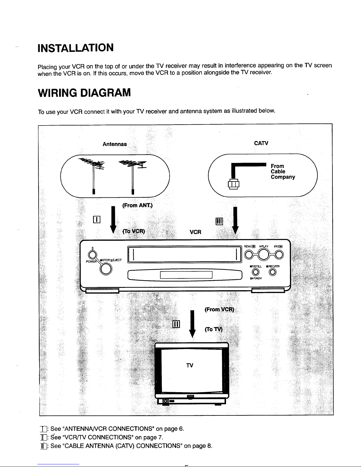
-- INSTALLATION
Placing your VCR on the top of or under the TV receiver may result in interference appearing on the TV screen
when the VCR is on. If this occurs, move the VCR to a position alongside the TV receiver.
WIRING DIAGRAM
To use your VCR connect it with your TV receiver and antenna system as illustrated below.
Antennas !i! i;!:
_ r I_ From
Cable
Company
=!
EJECT
(From ANT.)
-_1 ¸. > -
I
I i
VCR
lIp/STILL ORECATR
© ©
III, F/ADV
• -:)
(FromYCR):::,
-]_: See "ANTENNA/VCR CONNECTIONS" on page 6.
_: See "VCRiTV CONNECTIONS" on page 7.
]_: See "CABLE ANTENNA (CATV) CONNECTIONS" on page 8.
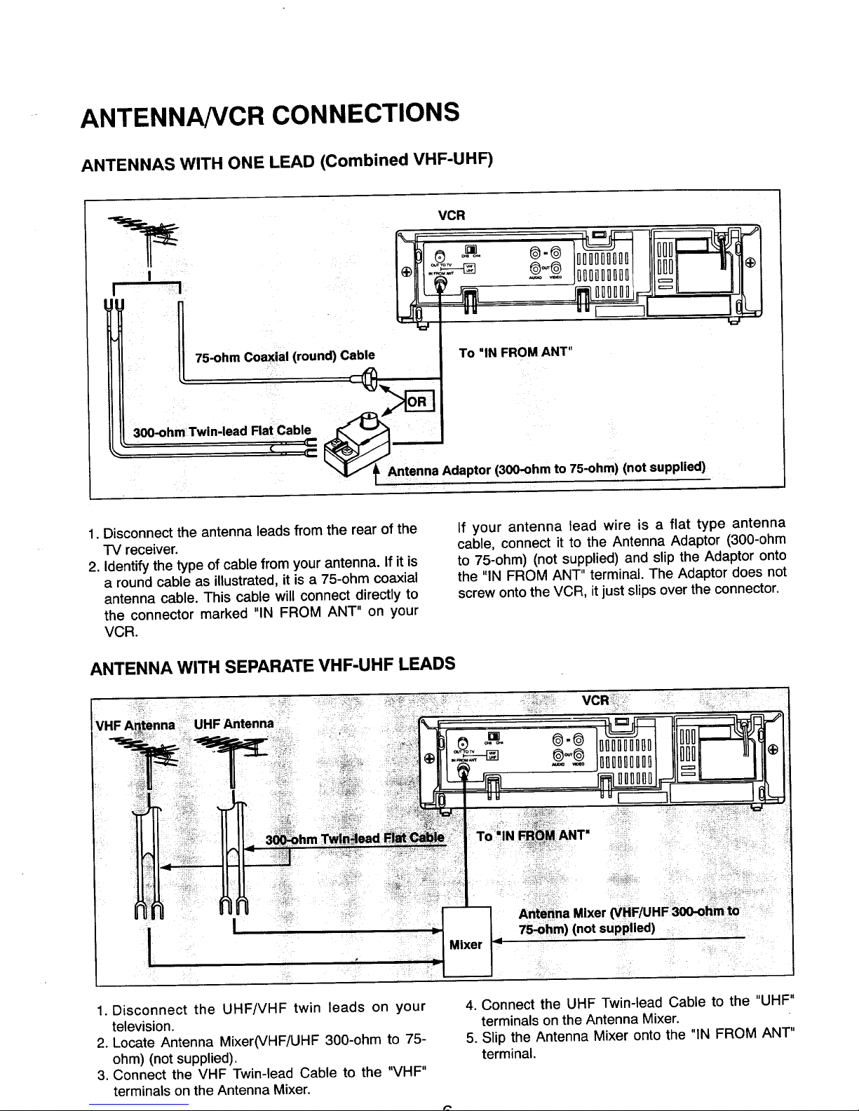
ANTENNANCR CONNECTIONS
ANTENNAS WITH ONE LEAD (Combined VHF-UHF)
VCR
%__
75-ohm Coaxial (round) Cable
300-ohm Twin-lead
Flat Cable
DOff@'@ OI]O_]Ql]OI]O
_'_ IOOl]_OUo_OLiDI]D
,, F---ql
To "IN FROM ANT"
..... Adaptor(3_-ohm to 7S-ohm)(notsupplied)
7
@
1. Disconnect the antenna leads from the rear of the
"iV receiver.
2. Identify the type of cable from your antenna. If it is
a round cable as illustrated, it is a 75-ohm coaxial
antenna cable. This cable will connect directly to
the connector marked "IN FROM ANT" on your
VCR.
If your antenna lead wire is a flat type antenna
cable, connect it to the Antenna Adaptor (300-ohm
to 75-ohm) (not supplied) and slip the Adaptor onto
the "IN FROM ANT" terminal. The Adaptor does not
screw onto the VCR, it just slips over the connector.
ANTENNA WITH SEPARATE VHF-UHF LEADS
I
1. Disconnect the UHF/VHF twin leads on your
television.
2. Locate Antenna Mixer(VHF/UHF 300-ohm to 75-
ohm) (not supplied).
3. Connect the VHF Twin-lead Cable to the "VHF"
terminals on the Antenna Mixer.
4. Connect the UHF Twin-lead Cable to the "UHF"
terminals on the Antenna Mixer.
5. Slip the Antenna Mixer onto the "IN FROM ANT"
terminal.
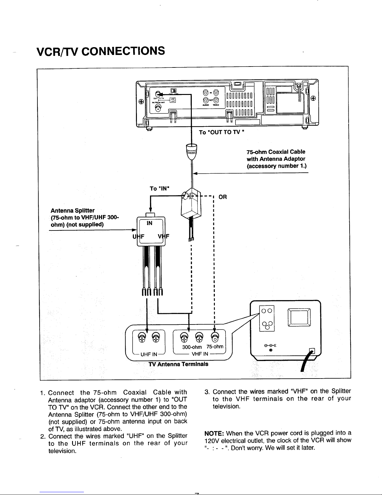
- VCRFI'V CONNECTIONS
Antenna Splitter
(75-ohm to VHF/UHF 300-
ohm) (not supplied)
%=
To "IN"
®-® ionDnonnnn
jooooonooo
DI]OOOD
To "OUT TO TV"
--I OR
q
"LI
I
75-ohm Coaxial Cable
with Antenna Adaptor
(accessory number 1.)
TV Antenna Terminals
1. Connect the 75-ohm Coaxial Cable with
Antenna adaptor (accessory number 1) to "OUT
TO TV" on the VCR. Connect the other end to the
Antenna Splitter (75-ohm to VHF/UHF 300-ohm)
(not supplied) or 75-ohm antenna input on back
of TV, as illustrated above.
2. Connect the wires marked "UHF" on the Splitter
to the UHF terminals on the rear of your
television.
3. Connect the wires marked "VHF" on the Splitter
to the VHF terminals on the rear of your
television.
NOTE: When the VCR power cord is plugged into a
120V electrical outlet, the clock of the VCR will show
"- • - - ". Don't worry. We will set it later.
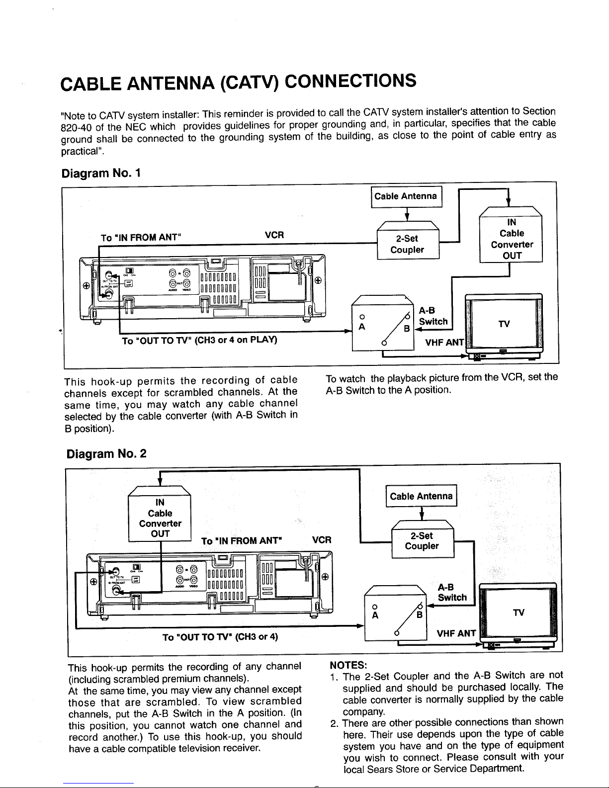
CABLE ANTENNA (CATV) CONNECTIONS
"Note to CATV system installer: This reminder is provided to call the CA'FV system installer's attention to Section
820-40 of the NEC which provides guidelines for proper grounding and, in particular, specifies that the cable
ground shall be connected to the grounding system of the building, as close to the point of cable entry as
practical".
Diagram No. 1
To "IN FROM ANT" VCR
®'® nDon[loonDI]l]fl @
To "OUT TO TV" (CH3 or 4 on PLAY)
,Ca ,e;n,enn ,[I'
_/ 2-Set J_._..I claNle
| Coupler J C°nverter I
OUT |
I
o
TV
I VHF ANT
I , _=- == _1
This hook-up permits the recording of cable
channels except for scrambled channels. At the
same time, you may watch any cable channel
selected by the cable converter (with A-B Switch in
B position).
To watch the playback picture from the VCR, set the
A-B Switch to the A position.
Diagram No. 2
To "IN FROM ANT" VCR
I I*ll_: I _ 1oiiiaiiiilII1_i "ilFI
To "OUT TO IV" (CH3 or 4)
I Cable Antenna I
t
-Se,
Coupler _]
So
- VHFAN TV
1
i J
m
This hook-up permits the recording of any channel
(including scrambled premium channels).
At the same time, you may view any channel except
those that are scrambled. To view scrambled
channels, put the A-B Switch in the A position. (In
this position, you cannot watch one channel and
record another.) To use this hook-up, you should
have a cable compatible television receiver.
NOTES:
1. The 2-Set Coupler and the A-B Switch are not
supplied and should be purchased locally. The
cable converter is normally supplied by the cable
company.
2. There are other •possible connections than shown
here. Their use depends upon the type of cable
system you have and on the type of equipment
you wish to connect. Please consult with your
local Sears Store or Service Department.
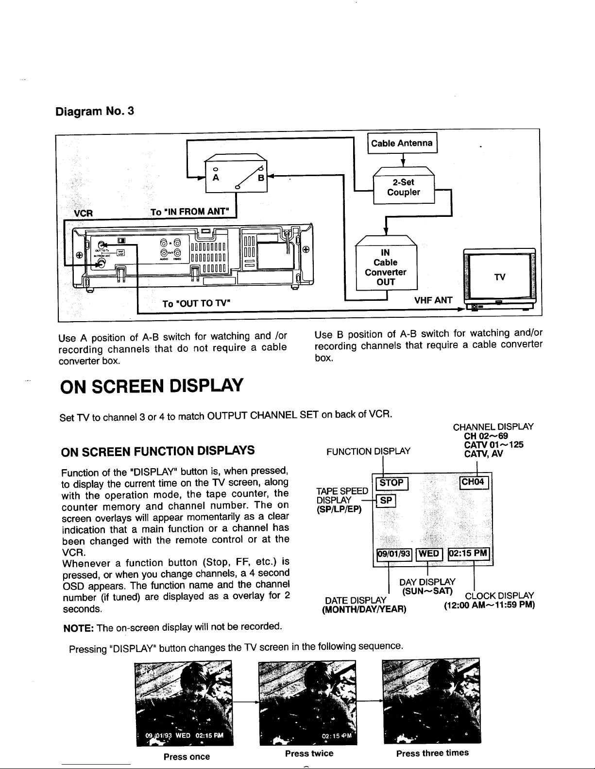
Diagram No. 3
To "INFROM ANT"
= -- ®.®
1
To "OUT TO TV"
i
I
100aa0uHal l 'I II- I
_l_a. Ill I
I Cable Antenna I
2-Set _
Coupler
IN
Cable
I Converter
/ OUT TV
I VHF ANT --
Use A position of A-B switch for watching and /or
recording channels that do not require a cable
converter box.
Use B position of A-B switch for watching and/or
recording channels that require a cable converter
box.
ON SCREEN DISPLAY
Set TV to channel 3 or 4 to match OUTPUT CHANNEL SET on back of VCR.
ON SCREEN FUNCTION DISPLAYS
Function of the "DISPLAY" button is, when pressed,
to display the current time on the TV screen, along
with the operation mode, the tape counter, the
counter memory and channel number. The on
screen overlays will appear momentarily as a clear
indication that a main function or a channel has
been changed with the remote control or at the
VCR.
Whenever a function button (Stop, FF, etc.) is
pressed, or when you change channels, a 4 second
OSD appears. The function name and the channel
number (if tuned) are displayed as a overlay for 2
seconds.
FUNCTION DISPLAY
TAPE SPEED
DISPLAY --
(SP/LP/EP)
CHANNEL DISPLAY
CH 02"-69
CATV 01"--125
CATV,AV
....
DATE DISPLAY
(MONTH/DAY/YEAR)
(12:00 AM_-11:59 PM)
NOTE: The on-screen display will not be recorded.
Pressing "DISPLAY" button changes the TV screen in the following sequence.
Press once Press twice Press three times
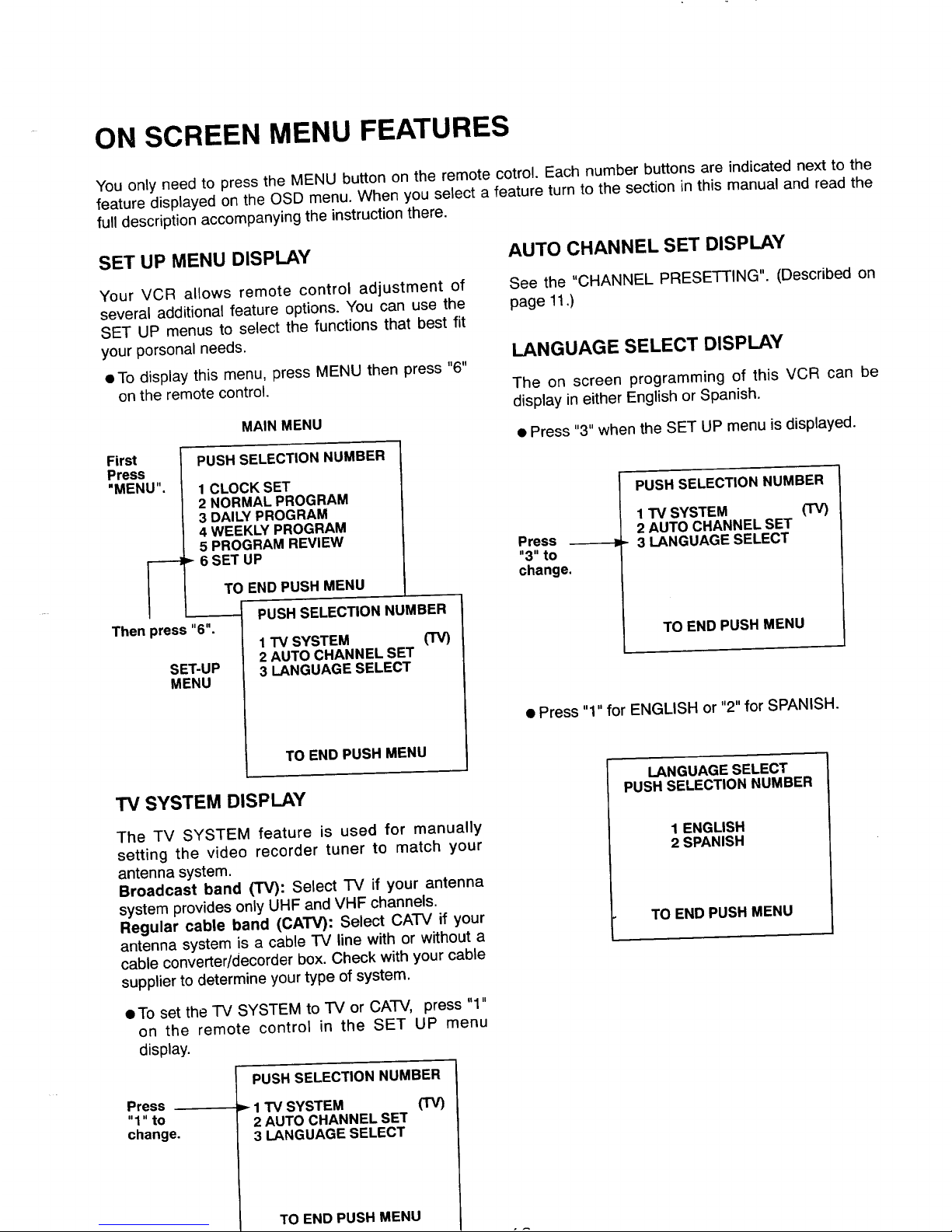
ON SCREEN MENU FEATURES
You only need to press the MENU button on the remote cotrol. Each number buttons are indicated next to the
feature displayed on the OSD menu. When you select a feature turn to the section in this manual and read the
full description accompanying the instruction there.
SET UP MENU DISPLAY
AUTO CHANNEL SET DISPLAY
Your VCR allows remote control adjustment of
several additional feature options. You can use the
SET UP menus to select the functions that best fit
your porsonal needs.
• To display this menu, press MENU then press "6"
on the remote control.
MAIN MENU
First
Press
"MENU".
Then press "6".
SET-UP
MENU
PUSH SELECTION NUMBER
1 CLOCK SET
2 NORMAL PROGRAM
3 DALLY PROGRAM
4 WEEKLY PROGRAM
5 PROGRAM REVIEW
'_ 6 SET UP
TO END PUSH MENU
PUSH SELECTION NUMBER
1 TV SYSTEM (TV)
2 AUTO CHANNEL SET
3 LANGUAGE SELECT
TO END PUSH MENU
TV SYSTEM DISPLAY
The TV SYSTEM feature is used for manually
setting the video recorder tuner to match your
antenna system.
Broadcast band (TV): Select TV if your antenna
system provides only UHF and VHF channels.
Regular cable band (CATV): Select CATV if your
antenna system is a cable TV line with or without a
cable converter/decorder box. Check with your cable
supplier to determine your type of system.
See the "CHANNEL PRESETTING". (Described on
page 11.)
LANGUAGE SELECT DISPLAY
The on screen programming of this VCR can be
display in either English or Spanish.
• Press "3" when the SET UP menu is displayed.
Press
"3"to
change.
PUSH SELECTION NUMBER
1 TV SYSTEM (TV)
2 AUTO CHANNEL SET
3 LANGUAGE SELECT
TO END PUSH MENU
• Press "1" for ENGLISH or "2" for SPANISH.
LANGUAGE SELECT
PUSH SELECTION NUMBER
1 ENGLISH
2 SPANISH
TO END PUSH MENU
• To set the "IV SYSTEM to TV or CATV, press "1"
on the remote control in the SET UP menu
display.
Press
"1"to
change,
PUSH SELECTION NUMBER
-_ 1 TV SYSTEM (TV)
2 AUTO CHANNEL SET
3 LANGUAGE SELECT
TO END PUSH MENU
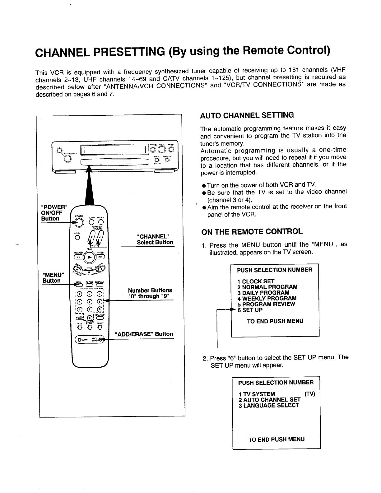
CHANNEL PRESETTING (By using the Remote Control)
This VCR is equipped with a frequency synthesized tuner capable of receiving up to 181 channels (VHF
channels 2-13, UHF channels 14-69 and CATV channels 1-125), but channel presetting is required as
described below after "ANTENNA/VCR CONNECTIONS" and "VCR/TV CONNECTIONS" are made as
described on pages 6 and 7.
L ]
"POWER"
ON/OFF
Button
"MENU"
Button
CLEAR BSmAY
I
I0 Q ®1
',® ® ®',=
I I
, _®j,® ®_
- - 1 I sp,LP_P
-N
©@©
"CHANNEL"
Select Button
Number Buttons
"0" through "9"
"ADD/ERASE" Button
AUTO CHANNEL SETTING
The automatic programming feature makes it easy
and convenient to program the -rv station into the
tuner's memory.
Automatic programming is usually a one-time
procedure, but you will need to repeat it if you move
to a location that has different channels, or if the
power is interrupted.
• Turn on the power of both VCR and TV.
• Be sure that the TV is set to the video channel
(channel 3 or 4).
• Aim the remote control at the receiver on the front
panel of the VCR.
ON THE REMOTE CONTROL
1. Press the MENU button until the "MENU", as
illustrated, appears on the TV screen.
PUSH SELECTION NUMBER
1 CLOCK SET
2 NORMAL PROGRAM
3 DAILY PROGRAM
4 WEEKLY PROGRAM
5 PROGRAM REVIEW
6 SET UP
TO END PUSH MENU
2. Press "6" button to select the SET UP menu. The
SET UP menu will appear.
PUSH SELECTION NUMBER
1 TV SYSTEM (TV)
2 AUTO CHANNEL SET
3 LANGUAGE SELECT
TO END PUSH MENU
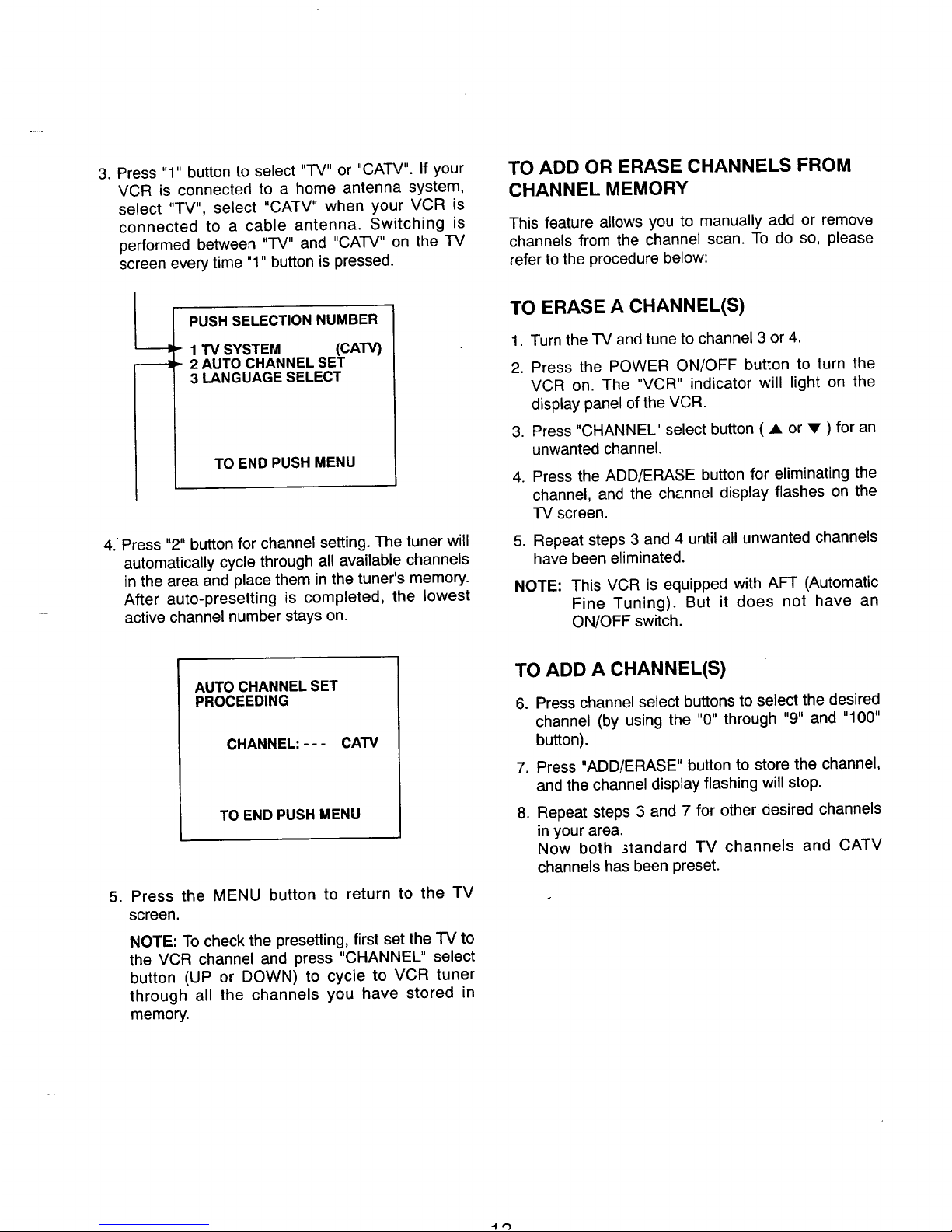
3. Press "1" button to select "IV" or "CATV". If your
VCR is connected to a home antenna system,
select "TV", select "CATV" when your VCR is
connected to a cable antenna. Switching is
performed between "TV" and "CATV" on the TV
screen every time "1" button is pressed.
PUSH SELECTION NUMBER
" 1 TV SYSTEM (CATV)
=- 2 AUTO CHANNEL SET
3 LANGUAGE SELECT
TO END PUSH MENU
4. Press "2" button for channel setting. The tuner will
automatically cycle through all available channels
in the area and place them in the tuner's memory.
After auto-presetting is completed, the lowest
active channel number stays on.
TO ADD OR ERASE CHANNELS FROM
CHANNEL MEMORY
This feature allows you to manually add or remove
channels from the channel scan. To do so, please
refer to the procedure below:
TO ERASE A CHANNEL(S)
1. Turn the TV and tune to channel 3 or 4.
2. Press the POWER ON/OFF button to turn the
VCR on. The "VCR" indicator will light on the
display panel of the VCR.
3. Press "CHANNEL" select button ( A or • ) for an
unwanted channel.
4. Press the ADD/ERASE button for eliminating the
channel, and the channel display flashes on the
TV screen.
5. Repeat steps 3 and 4 until all unwanted channels
have been eliminated.
NOTE: This VCR is equipped with AFT (Automatic
Fine Tuning). But it does not have an
ON/OFF switch.
AUTO CHANNEL SET
PROCEEDING
CHANNEL: - - - CATV
TO END PUSH MENU
5. Press the MENU button to return to the TV
screen.
NOTE: To check the presetting, first set the TV to
the VCR channel and press "CHANNEL" select
button (UP or DOWN) to cycle to VCR tuner
through all the channels you have stored in
memory.
TO ADD A CHANNEL(S)
°
.
,
Press channel select buttons to select the desired
channel (by using the "0" through "9" and "100"
button).
Press "ADD!ERASE" button to store the channel,
and the channel display flashing will stop.
Repeat steps 3 and 7 for other desired channels
in your area.
Now both 3tandard TV channels and CATV
channels has been preset.
 Loading...