

Page 1

Gasoline containing up to 10% ethanol (EIO) is accept=
able for use in this machine. The use of any gasoline ex-
ceeding 10% ethanol(ElO) wiHvoidtheproductwarrantyo
Esta maquina puede utilizar gasolina con un contenido
de hasta e! 10% de etanol (E10)o EJuso de una gasolina
que supere el 10% de etanoi (EIO) anulata ta garantia
deJ productoo the product warranty°
585 98 55-96
Operator's Manual
Manuat de Operario
Please read the operator's manual carefully and make sure
you understand the instructions before using the machine.
Por favor lea cuidadosamente y comprenda
estas intrucciones antes de usar esta maquina.
Page 2
SAFETY RULES
Safe Operation Practices for Ride-On Mowers
DANGER: THiS CUTTING MACHINE iS CAPABLE OF AMPUTATING HANDS AND FEET AND THROWING OBJECTS. FAILURE
TO OBSERVE THE FOLLOWING SAFETY iNSTRUCTiONS COULD RESULT iN SERIOUS iNJURY OR DEATH.
WARNmNG: _n order to prevent accidental
starting when setting up, transporting,
adjusting or making repairs, always discon-
nect spark plug wire and place wire where
it cannot contact spark plug.
i WARNNNG_own a hill in neuto
ral, you may _ose eontro_ of the tractor.
WARNING: Tow onJy the attachments that
are recommended by and comply with
specifications of the manufacturer of your
tractor. Use common sense when towing.
Operate only at the lowest possible speed
when on a slope. Too heavy ofa load,while
on a slope, i8 dangerous. Tires can Jose
traction with the ground and cause you to
_ose eontro_ of your tractor.
WARNING
Engine exhaust, some of its constituents, and certain
vehieJe components contain or emit chemicals
known to the State of California to cause cancer
and birth defects or other reproductive harm.
WARNING
Battery posts, terminals and related accessories
contain lead and Jead compounds, chemicals known
to the State of California to cause cancer and birth
defects or other reproductive harm. Wash hands
after handling.
L GENERAL OPEF{AT_ON
o Read, understand, and follow all instructions on the ma-
chine and in the manual before starting.
o Do not put hands or feet near rotating parts or under the
machine. Keep clear of the discharge opening at all times.
o Only allow responsible adults, who are familiar with the
instructions, to operate the machine.
o Clear the area of objects such as rocks, toys, wire, etc.,
which could be picked up and thrown by the blades.
o Ensure the area is clear of bystanders before operating.
Stop machine if anyone enters the area.
o Never carry passengers.
o Do not mow in reverse unless absolutely necessary.
Always look down and behind before and while backing.
o Never direct discharged material toward anyone. Avoid
discharging material against a wall or obstruction. Material
may ricochet back toward the operator. Stop the blades
when crossing gravel surfaces.
o Do not operate machine without the entire grass catcher,
discharge chute, or other safety devices in place and
working.
o Slow down before turning.
o Never leave a running machine unattended. Always turn
off blades, set parking brake, stop engine, and remove
keys before dismounting.
o Disengage blades when not mowing. Shut off engine
and wait for all parts to come to a complete stop before
cleaning the machine, removing the grass catcher, or
unclogging the discharge chute.
o Operate machine only in daylight or good artificial light.
o Do not operate the machine while under the influence of
alcohol or drugs.
o Watch for trafficwhen operating near or crossing roadways.
o Use extra care when loading or unloading the machine
into a trailer or truck.
o Always wear eye protection when operating machine.
o Data indicates that operators, age 60 years and above,
are involved in a large percentage of riding mower-related
injuries. These operators should evaluate their ability to
operate the riding mower safely enough to protect them-
selves and others from serious injury.
o Follow the manufacturer's recommendation for wheel
weights or counterweights.
o Keep machine free of grass, leaves or other debris build-up
which can touch hot exhaust / engine parts and burn. Do
not allow the mower deck to plow leaves or other debris
which can cause build-up to occur. Clean any oil or fuel
spillage before operating or storing the machine. Allow
machine to cool before storage.
HoSLOPE OPERATION
Slopes are a major factor related to loss of control and tip-
over accidents, which can result in severe injury or death.
Operation on all slopes requires extra caution. If you cannot
back up the slope or if you feel uneasy on it, do not mow it.
o Mow up and down slopes, not across.
o Watch for holes, ruts, bumps, rocks, or other hidden ob-
jects. Uneven terrain could overturn the machine. Tall
grass can hide obstacles.
o Choose a low ground speed so that you will not have to
stop or shift while on the slope.
o Do not mow on wet grass. Tires may lose traction.
Always keep the machine in gear when going down slopes.
Do not shift to neutral and coast downhill.
o Avoid starting, stopping, or turning on a slope. If the tires
lose traction, disengage the blades and proceed slowly
straight down the slope.
o Keep all movement on the slopes slow and gradual. Do
not make sudden changes in speed or direction, which
could cause the machine to roll over.
o Use extra care while operating machine with grass catch-
ers or other attachments; they can affect the stability of
the machine. Do no use on steep slopes.
o Do not try to stabilize the machine by putting your foot on
the ground.
o Do not mow near drop-offs, ditches, or embankments.
The machine could suddenly roll over if a wheel is over
the edge or if the edge caves in.
2
Page 3
SAFETY RULES
Safe Operation Practices for Ride-On Mowers
ill. CHILDREN
WARNING. CHILDREN CAN BE iNJURED BY
TH_S EQUIPMENT. The American Academy
of Pediatrics recommends that children be a
minimum of 12 year of age before operating
a pedestrian controlled _awn mower and a
minimum of 16 years of age before operating
a riding lawn mower.
Tragic accidents can occur if the operator is not alert to the
presence of children. Children are often attracted to the ma=
chine and the mowing activity. Never assume that children
will remain where you last saw them.
o Keep children out of the mowing area and in the watchful
care of a responsible adult other than the operator.
o Be alert and turn machine off if a child enters the area.
o Before and wNle backing, look beMnd and down for small
children.
o Never carry children, even with the blades shut off. They
may fall off and be seriously injured or interfere with safe
machine operation. Children who have been given rides
in the past may suddenly appear in the mowing area for
another ride and be run over or backed over by the machine.
o Never allow children to operate the machine.
o Use extra care when approaching blind corners, shrubs,
trees, or other objects that may block your view of a child.
o If fuel is spilled on clothing, change clothing immediately.
o Never overfill fuel tank. Replace gas cap and tighten
securely.
GENERAL SERWCE
o Never operate machine in a closed area.
o Keep all nuts and bolts tight to ensure the equipment is
in safe working condition.
o Never tamper with safety devices. Check their proper
operation regularly.
o Keep machine free of grass, leaves, or other debris build=
up. Clean oil or fuel spillage and remove any fuel-soaked
debris. Allow machine to cool before storing.
o Ifyou strike a foreign object, stop and inspect the machine.
Repair, if necessary, before restarting.
o Never make any adjustments or repairs with the engine
running.
o Check grass catcher components and the discharge chute
frequently and replace with manufacturer's recommended
parts, when necessary.
o Mower blades are sharp. Wrap the blade or wear gloves,
and use extra caution when servicing them.
o Check brake operation frequently. Adjust and service as
required.
o Maintain or replace safety and instruction labels, as nec=
essary.
_VoTOWING
o Tow only with a machine that has a hitch designed for
towing. Donot attach towed equipment except atthe hitch
point.
o Follow the manufacturer's recommendation for weight
limits for towed equipment and towing on slopes.
o Never allow children or others inor on towed equipment.
o On slopes, the weight ofthe towed equipment may cause
loss of traction and loss of control.
o Travel slowly and allow extra distance to stop.
V. SERVICE
SAFE HANDUNG OF GASOLINE
To avoid personal injury or property damage, use extreme
care in handling gasoline. Gasoline is extremely flammable
and the vapors are explosive.
o Extinguish all cigarettes, cigars, pipes, and other sources
of ignition.
o Use only approved gasoline container.
o Never remove gas cap or add fuel with the engine running.
Allow engine to cool before refueling.
o Never fuel the machine indoors.
o Never store the machine or fuet container where there
is an open flame, spark, or pilot light such as on a water
heater or other appliances.
o Never fill containers inside a vehicle or on a truck or
trailer bed with plastic liner. Always place containers on
the ground away from your vehicle when filling.
o Remove gas=powered equipment from the truck or trailer
and refuel it on the ground. If this is not possible, then
refuel such equipment with a portable container, rather
than from a gasoline dispenser nozzle.
o Keep the nozzle in contact with the rim of the fuel tank or
container opening at all times until fueling is complete.
Do not use a nozzle lock=open device.
o Ensure the area is clear of bystanders before operating.
Stop machine if anyone enters the area.
o Never carry passengers.
o Do not mow in reverse unless absolutely necessary.
Always look down and behind before and while backing.
o Never carry children, even with the blades shut off. They
may fall off and be seriously injured or interfere with safe
machine operation. Children who have been given rides
in the past may suddenly appear in the mowing area
for another ride and be run over or backed over by the
machine.
o Keep children out of the mowing area and in the watchful
care of a responsible adult other than the operator.
o Be alert and turn machine off if a child enters the area.
o Before and while backing, look behind and down for small
children.
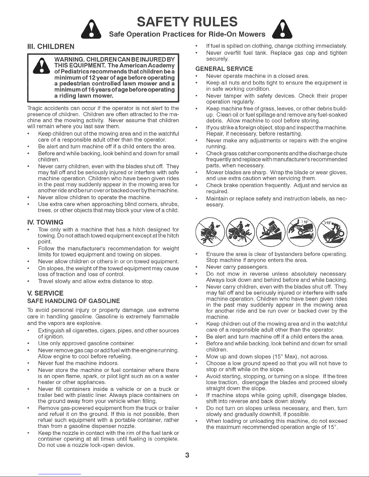
o Mow up and down slopes (15 ° Max), not across.
o Choose a low ground speed so that you will not have to
stop or shift while on the slope.
o Avoid starting, stopping, or turning on a slope. If the tires
lose traction, disengage the blades and proceed slowly
straight down the slope.
o If machine stops while going uphill, disengage blades,
shift into reverse and back down slowly.
o Do not turn on slopes unless necessary, and then, turn
slowly and gradually downhill, if possible.
o When loading or unloading this machine, do not exceed
the maximum recommended operation angle of 15°.
3
Page 4
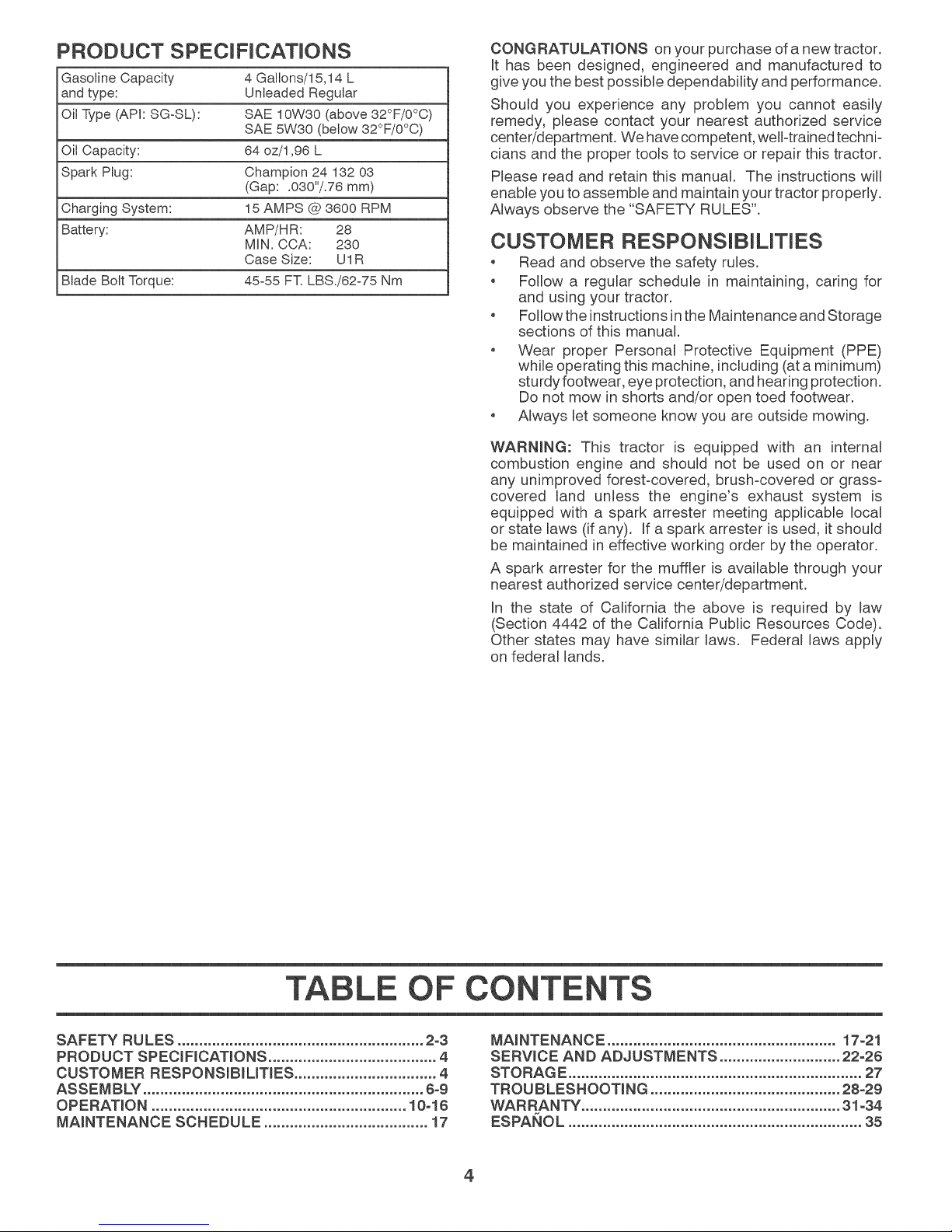
PRODUCT SPECiFiCATiONS
Gasoline Capacity 4 Gallons/15,14 L
and type: Unleaded Regular
Oil Type (API: SGoSL): SAE 10W30 (above 32°F/0°0)
SAE 5W30 (below 32°F/0°0)
Oil Capacity: 64 oz/1,96 L
Spark Plug: Champion 24 132 03
(Gap: .030"/.76 mm)
Charging System: 15 AMPS @ 3600 RPM
Battery: AMP/HR: 28
MIN. CCA: 230
Case Size: UI R
Blade Bolt Torque: 45°55 FT. LBS./62-75 Nm
CONGRATULATmONS on your purchase of a new tractor.
It has been designed, engineered and manufactured to
give you the best possible dependability and performance.
Should you experience any problem you cannot easily
remedy, please contact your nearest authorized service
center/department. We have competent, weH-trainedtechni-
cians and the proper tools to service or repair this tractor.
Please read and retain this manual. The instructions will
enable you to assemble and maintain your tractor properly.
Always observe the "SAFETY RULES".
CUSTOMER RESPONSJB LMES
Road and observe the safety rules.
Follow a regular schedule in maintaining, caring for
and using your tractor.
Follow the instructions in the Maintenance and Storage
sections of this manual.
Wear proper Personal Protective Equipment (PPE)
while operating this machine, including (at a minimum)
sturdy footwear, eye protection, and hearing protection.
Do not mow in shorts and/or open toed footwear.
Always let someone know you are outside mowing.
WARNNNG: This tractor is equipped with an internal
combustion engine and should not be used on or near
any unimproved forest-covered, brush-covered or grass-
covered land unless the engine's exhaust system is
equipped with a spark arrester meeting applicable local
or state laws (if any). If a spark arrester is used, it should
be maintained in effective working order by the operator.
A spark arrester for the muffler is available through your
nearest authorized service center/department.
In the state of California the above is required by law
(Section 4442 of the California Public Resources Code).
Other states may have similar laws. Federal laws apply
on federal lands.
TABLE OF CONTENTS
SAFETY RULES ......................................................... 2-3
PRODUCT SPECIFmCAT_ONS....................................... 4
CUSTOMER RESPONSmBILMES ................................. 4
ASSEMBLY ................................................................. 6°9
OPERATION ........................................................... 10o16
MAINTENANCE SCHEDULE ...................................... 17
MAINTENANCE ..................................................... 17-21
SERWCE AND ADJUSTMENTS ............................ 22-26
STORAGE .................................................................... 27
TROUBLESHOOTING ............................................ 28-29
WARRANTY ............................................................ 31-34
ESPANOL .................................................................... 35
4
Page 5

UNASSEMBLED
(5)1-3/16
O.D. Washers
(5) Large
Retainer Springs
Mower
Mower Front Wheel
0
(1) Shoutder Bolt
(i) 1-i/40.O.
Washer
(1)3/8-1e
(1) Wheel
If Equipped
*installed by Dealer
(1) Anti-Sway Bar
Keys
(2) Keys
(1)3/40oD.
Washers
(1) Oil Drain Tube
(1) Quick Connect
(1) Smalt Retainer
Springs
*Brush Guard Kit
Slope Sheet
5
Page 6
ASSEMBLY
Your new tractor has been assembled at the factory with exception of those parts left unassembled for shipping purposes.
To ensure safe and proper operation of your tractor all parts and hardware you assemble must be tightened securely. Use
the correct tools as necessary to ensure proper tightness.
TOOLS REQUIRED FOR ASSEMBLY
A socket wrench set will make assembly easier. Standard
wrench sizes are listed.
(2) 7/16" wrenches Utility knife
(1) 1/2" wrench Tire pressure gauge
(1) 3/4" wrench Pliers
(1) 3/4" socket w/drive ratchet
(1) 9/16" wrench Flashlight
When right or left hand ismentioned in this manual, itmeans
when you are in the operating position (seated behind the
steering wheel).
TO REMOVE TRACTOR FROM CARTON
UNPACK CARTON
, Remove all accessible loose parts and parts cartons
from carton.
Remove end panels and lay side panels flat.
Remove mower and packing materials.
Check for any additional loose parts or cartons and
remove.
BEFORE REMOWNG TRACTOR FROM
SKID
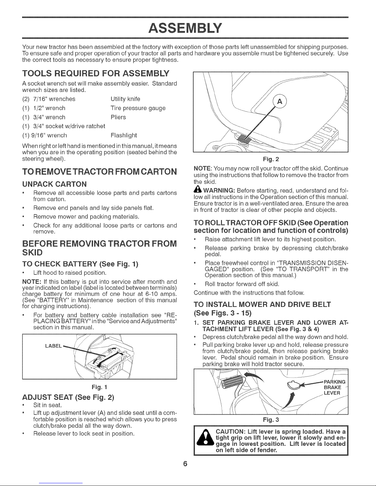
TO CHECK BATTERY (See Fig. 1)
o Lift hood to raised position.
NOTE: If this battery is put into service after month and
year indicated on labem(label is located between terminals)
charge battery for minimum of one hour at 6-10 amps.
(See "BATTERY" in Maintenance section of this manual
for charging instructions).
For battery and battery cable installation see "RE-
PLACING BATTERY" inthe "Service and Adjustments"
section in this manual.
NOTE: You may now roll your tractor off the skid. Continue
using the instructions that follow to remove the tractor from
the skid.
_, WARNLNG: Before starting, read, understand and fol-
low all instructions in the Operation section of this manual.
Ensure tractor is in a well-ventilated area. Ensure the area
in front of tractor is clear of other people and objects.
TO ROLLTRACTOR OFF SKiD (See Operation
section for location and function of controls}
, Raise attachment lift lever to its highest position.
o Release parking brake by depressing clutch/brake
pedal.
, Place freewheel control in "TRANSMISSION DISEN=
GAGED" position. (See "TO TRANSPORT" in the
Operation section of this manual.)
o Roll tractor forward off skid.
Continue with the instructions that follow.
TO INSTALL MOWER AND DRIVE BELT
(See Figs. 3 - 15}
1. SET PARKbNG BRAKE LEVER AND LOWER AT°
TAOHMENT L_FT LEVER (See Fig. 3 & 4}
, Depress clutch/brake pedal all the way down and hold.
, Pull parking brake lever up and hold, release pressure
from clutch/brake pedal, then release parking brake
lever. Pedal should remain in brake position. Ensure
parking brake will hold tractor secure.
Fig. 2
Fig. 1
ADJUST SEAT (See Fig. 2)
Sit in seat.
Lift up adjustment lever (A) and slide seat until a com-
fortable position is reached which allows you to press
clutch/brake pedal all the way down.
Release lever to lock seat in position.
PARKING
BRAKE
Fig. 3
CAUTION: Lift lever i8 spring loaded. Have a
tight grip on lift lever, lower it slowly and en-
gage in _owest position. Lift _ever i8 _oeated
on _eft side of fender.
6
Page 7
ASSEMBLY
LIFT
Fig. 4
2_
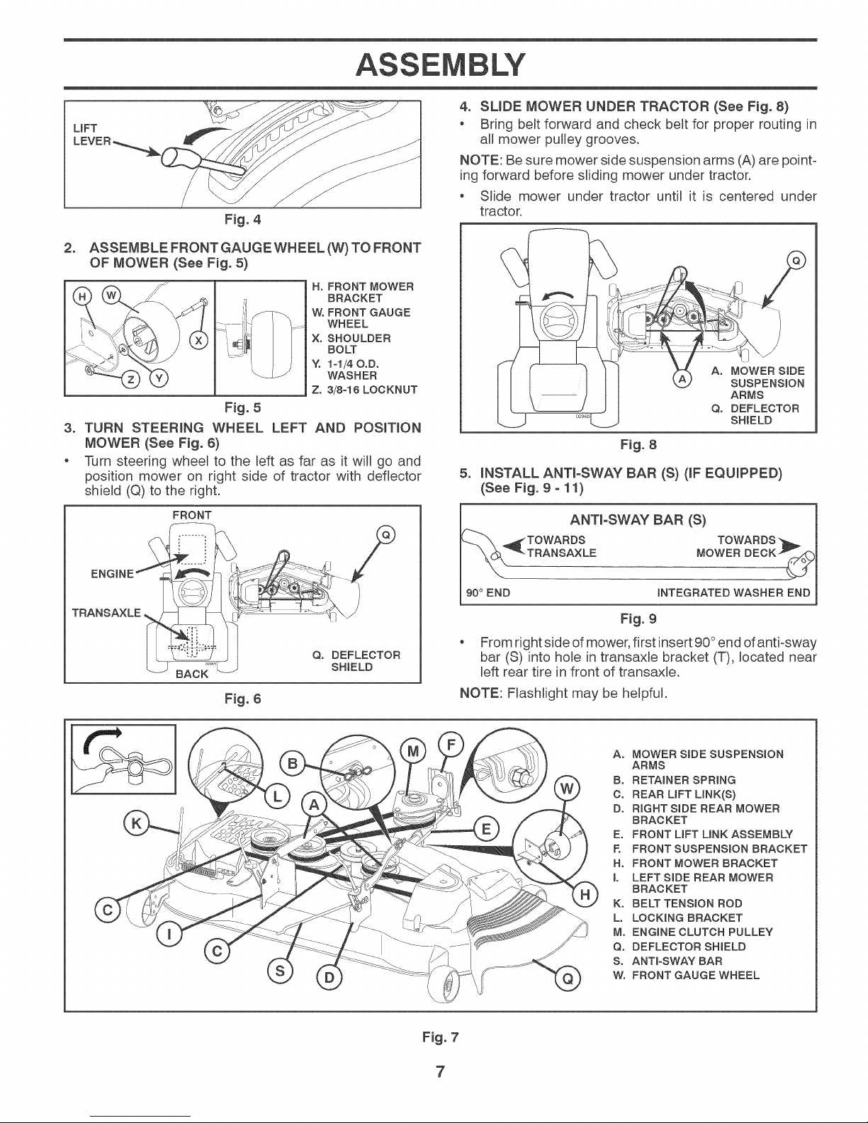
ASSEMBLE FRONT GAUGE WHEEL (W) TO FRONT
OF MOWER (See Fig. 5)
H, FRONT MOWER
BRACKET
WoFRONT GAUGE
WHEEL
X, SHOULDER
BOLT
Y. I-I/40oD.
WASHER
Zo 3/8-16 LOCKNUT
Fig. 5
3_
TURN STEERING WHEEL
MOWER (See Fig. 6)
e
Turn steering wheel to the left as far as it will go and
position mower on right side of tractor with deflector
shield (Q) to the right.
FRONT
LEFT AND POS_T_ON
4. SLIDE MOWER UNDER TRACTOR (See Fig. 8)
Bring belt forward and check belt for proper routing in
all mower pulley grooves.
NOTE: Be sure mower side suspension arms (A) are point-
ing forward before sliding mower under tractor.
Slide mower under tractor until it is centered under
tractor.
Ao MOWER SiDE
SUSPENSION
ARMS
Qo DEFLECTOR
SHIELD
Fig. 8
5_
INSTALL ANTI-SWAY BAR (S) OF EQUIPPED)
(See Fig. 9 - 11)
ANT_-SWAY BAR (S)
TRANSAXLE
Fig. 6
Qo DEFLECTOR
SHIELD
:ITOWARDS TOWARDS
TRANSAXLE MOWER DECK _
90° END INTEGRATED WASHER END
Fig. 9
From right side of mower, first insert 90°end of anti-sway
bar (S) into hole in transaxle bracket (T), located near
left rear tire in front of transaxle.
NOTE: Flashlight may be helpful.
Ao MOWER S_DE SUSPENSION
ARMS
Bo RETAINER SPRING
C. REAR UFT LINK(S)
D° RIGHT SIDE REAR MOWER
BRACKET
E. FRONT UFT UNK ASSEMBLY
R FRONT SUSPENSION BRACKET
Ho FRONT MOWER BRACKET
L LEFTSIDE REAR MOWER
BRACKET
K° BELT TENSION ROD
L° LOCKING BRACKET
M° ENGINE CLUTCH PULLEY
Q° DEFLECTOR SHIELD
S. ANTra-SWAY BAR
Wo FRONT GAUGE WHEEL
Fig. 7
7
Page 8
ASSEMBLY
ANTI-SWAY BAR
(s)
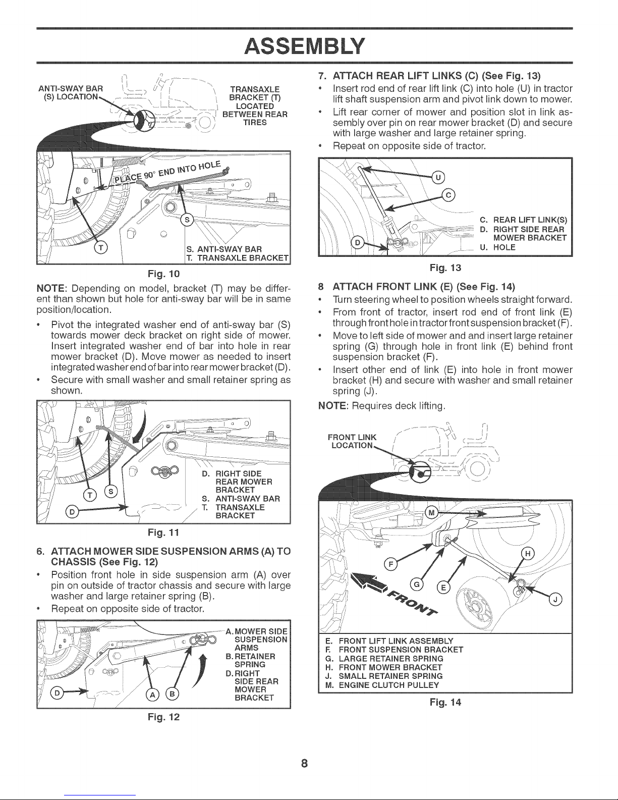
NOTE: Depending on model, bracket (T) may be differ-
ent than shown but hole for anti-sway bar will be in same
position/location.
Pivot the integrated washer end of anti-sway bar (S)
towards mower deck bracket on right side of mower.
Insert integrated washer end of bar into hole in rear
mower bracket (D). Move mower as needed to insert
integrated washer end of bar into rearmower bracket (D).
Secure with small washer and small retainer spring as
shown.
, ..................,_J"? TRANSAXLE
BRACKET (1")
LOCATED
BETWEEN REAR
/ TIRES
SoANTI-SWAY BAR
1". TRANSAXLE BRACKET
Fig. 10
7. ATTACH REAR LmFTUNKS (C) (See Fig. 13)
Insert rod end of rear lift link (C) into hole (U) in tractor
lift shaft suspension arm and pivot link down to mower.
o Lift rear corner of mower and position slot in link as-
sembly over pin on rear mower bracket (D) and secure
with large washer and large retainer spring.
o Repeat on opposite side of tractor.
C. REAR LiFT LINK(S)
Do RIGHT SiDE REAR
MOWER BRACKET
U° HOLE
Fig. 13
8 ATTACH FRONT MNK (E) (See Fig. 14)
qiarnsteering wheel to position wheels straight forward.
o From front of tractor, insert rod end of front link (E)
through front hole in tractor front suspension bracket (F).
Move to left side of mower and and insert large retainer
spring (G) through hole in front link (E) behind front
suspension bracket (F).
o Insert other end of link (E) into hole in front mower
bracket (H) and secure with washer and small retainer
spring (J).
NOTE: Requires deck lifting.
J. .... _ 1". TRANSAXLE
Y
/
BRACKET
Fig. 11
6. ATTACH MOWER SiDE SUSPENSION ARMS (A) TO
CHASSIS (See Fig. 12)
o Position front hole in side suspension arm (A) over
pin on outside of tractor chassis and secure with large
washer and large retainer spring (B).
o Repeat on opposite side of tractor.
BRACKET
Fig. 12
FRONT LiNK /
LOCATION,
Eo FRONT UFT LINK ASSEMBLY
E FRONT SUSPENSION BRACKET
G. LARGE RETAINER SPRING
H° FRONT MOWER BRACKET
J° SMALL RETAINER SPRING
M. ENGINE CLUTCH PULLEY
S ¸
F_g. 14
\
8
Page 9
ASSEMBLY
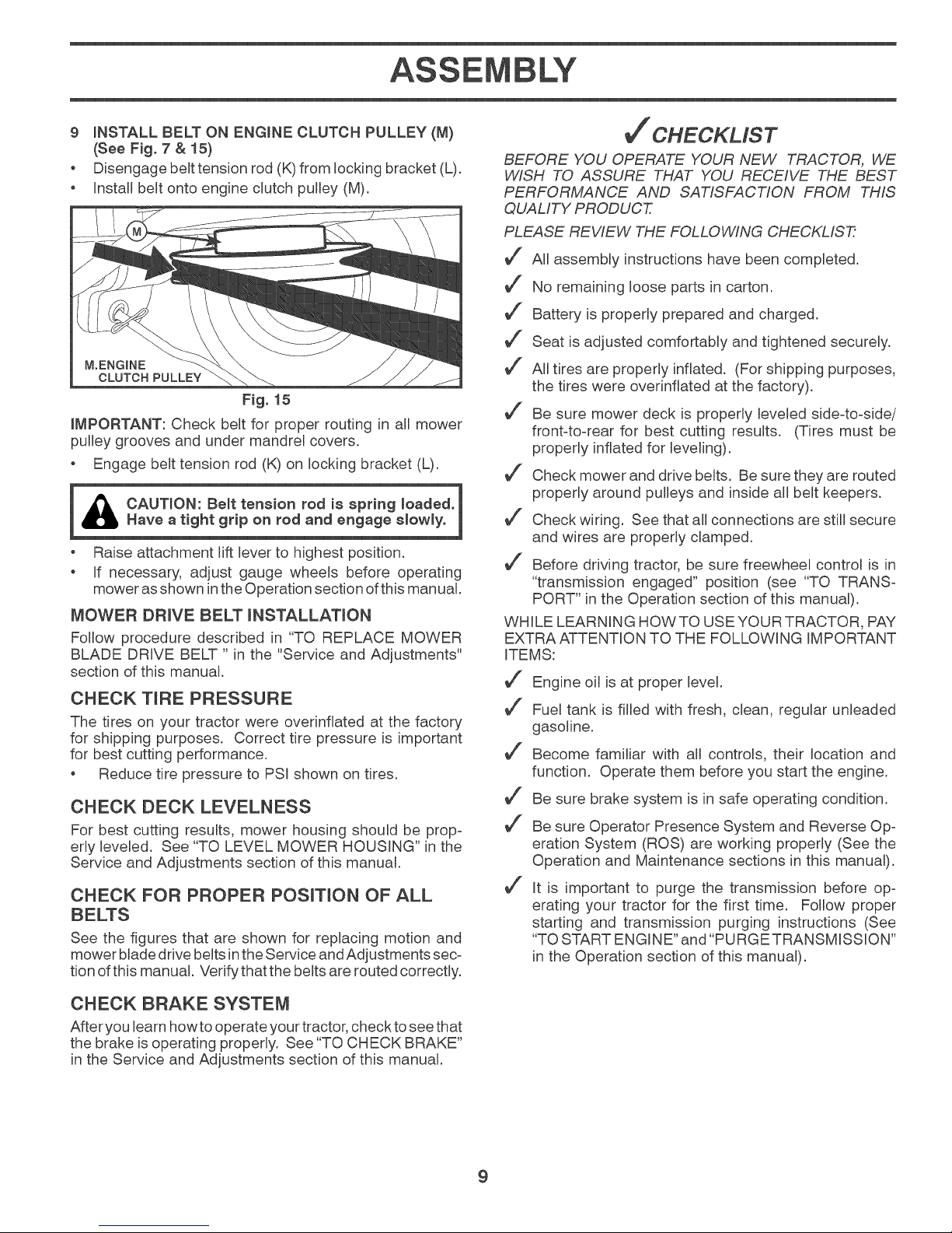
9 iNSTALL BELT ON ENGmNE CLUTCH PULLEY (M)
(See Fig. 7 & 15)
o Disengage belt tension rod (K)from locking bracket (L).
Install belt onto engine clutch pulley (M).
M.ENGINE
CLUTCH PULLEY
F_g. 15
iMPORTANT: Check belt for proper routing in all mower
pulley grooves and under mandrel covers.
o Engage belt tension rod (K) on locking bracket (L).
i CAUTION: Be_t tension rod is spring loaded. 1
_Have a tight grip on rod and engage slowly.
Raise attachment lift lever to highest position.
If necessary, adjust gauge wheels before operating
mower asshown in the Operation section of this manual.
MOWER DRIVE BELT _NSTALLATION
Follow procedure described in "TO REPLACE MOWER
BLADE DRIVE BELT " in the "Service and Adjustments"
section of this manual.
CHECK TIRE PRESSURE
The tires on your tractor were overinflated at the factory
for shipping purposes. Correct tire pressure is important
for best cutting performance.
Reduce tire pressure to PSI shown on tires.
CHECK DECK LEVELNESS
For best cutting results, mower housing should be prop-
erly leveled. See "TO LEVEL MOWER HOUSING" in the
Service and Adjustments section of this manual.
CHECK FOR PROPER POSIT_ON OF ALL
See the figures that are shown for replacing motion and
mower blade drive belts inthe Service and Adjustments sec=
tion ofthis manual. Verify that the belts are routed correctly.
BEFORE YOU OPERATE YOUR NEW TRACTOR, WE
WISH TO ASSURE THAT YOU RECEIVE THE BEST
PERFORMANCE AND SATISFACTION FROM THIS
QUALITY PRODUCT.
PLEASE REVIEW THE FOLLOWING CHECKLIST7
_J All assembly instructions have been completed.
_J No remaining loose parts in carton.
_J Battery is properly prepared and charged.
_J Seat is adjusted comfortably and tightened securely.
_J All tires are properly inflated. (For shipping purposes,
the tires were overinflated at the factory).
_J Be sure mower deck is properly leveled side=to=side/
front=to=rear for best cutting results. (Tires must be
properly inflated for leveling).
_J Check mower and drive belts. Be sure they are routed
properly around pulleys and inside all belt keepers.
_J Check wiring. See that all connections are still secure
and wires are properly clamped.
_J Before driving tractor, be sure freewheel control is in
"transmission engaged" position (see "TO TRANS-
PORT" in the Operation section of this manual).
WHILE LEARNING HOW TO USE YOUR TRACTOR, PAY
EXTRA ATTENTION TO THE FOLLOWING IMPORTANT
ITEMS:
_J Engine oil is at proper level.
_J Fuel tank is filled with fresh, clean, regular unleaded
gasoline.
_J Become familiar with all controls, their location and
function. Operate them before you start the engine.
_J Be sure brake system is in safe operating condition.
_J Be sure Operator Presence System and Reverse Op=
eration System (ROS) are working properly (See the
Operation and Maintenance sections in this manual).
_J It is important to purge the transmission before op=
erating your tractor for the first time. Follow proper
starting and transmission purging instructions (See
"TO START ENGINE" and "PURGE TRANSMISSION"
in the Operation section of this manual).
CHECK BRAKE SYSTEM
After you learn how to operate your tractor, check to see that
the brake is operating properly. See "TO CHECK BRAKE"
in the Service and Adjustments section of this manual.
9
Page 10
OPERATION
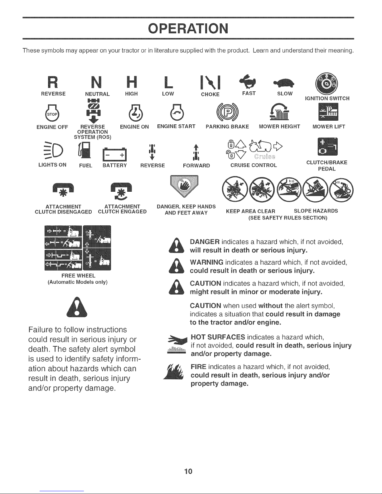
These symbols may appear on your tractor or in literature supplbd with the product. Learn and understand their meaning.
L 1\1
REVERSE NEUTRAL HmGH
LOW CHOKE FAST
SLOW
IGNITION SWITCH
ENGINE OFF REVERSE ENGINE ON ENGINE START PARKING BRAKE
LIGHTS ON FUEL BATTERY REVERSE FORWARD
ATTACHMENT ATTACHMENT
CLUTCH DISENGAGED CLUTCH ENGAGED
(Automatic Models only)
OPERATION
SYSTEM (ROS)
FREE WHEEL
DANGER, KEEP HANDS
AND FEETAWAY
DANGER indicates a hazard which, if not avoided,
will resumt in death or serious injury.
WARNING indicates a hazard which, if not avoided,
coumd resumt in death or serious injury.
CAUTION indicates a hazard which, if not avoided,
might resumt in minor or moderate injury.
CAUTION when used without the alert symbol,
indicates a situation that coumd resumt in damage
to the tractor and/or engine.
Failure to follow instructions
could result in serious injury or
death. The safety alert symbol
HOT SURFACES indicates a hazard which,
if not avoided, coumd resumt in death, serious injury
and/or property damage.
is used to identify safety inform-
ation about hazards which can
result in death, serious injury
NRE indicates a hazard which, if not avoided,
coumd result in death, serious injury and/or
property damage.
and/or property damage.
MOWER HEIGHT
CRUISE CONTROL
KEEP AREA CLEAR SLOPE HAZARDS
(SEE SAFETY RULES SECTION)
MOWER LIFT
CLUTCH/BRAKE
PEDAL
10
Page 11

OPERATION
KNOW YOUR TRACTOR
READ THIS MANUAL AND SAFETY RULES BEFORE OPERATING YOUR TRACTOR
Compare the illustrations with your tractor to familiarize yourself with the locations of various controls and adjustments.
Save this manual for future reference.
Our tractors conform to the applicable safety standards of the American National Standards Institute.
(A} ATTACHMENT UFT LEVER - Used to raise and lower
the mower or other attachments mounted to your tractor.
(B) BRAKE PEDAL - Used for braking the tractor and
starting the engine.
(C) PARKING BRAKE - Locks clutch/brake pedal into the
brake position.
(D) THROTTLE CONTROL- Used to control engine speed.
(E) ATTACHMENT CLUTCH SWmTCH- Used to engage
the mower blades, or other attachments mounted to your
tractor.
(F) NGNmT_ONSWITCH - Used for starting and stopping
the engine.
Fig. 16
(G) REVERSE OPERATmON SYSTEM (ROS) "ON"
POSIT_ON - Allows operation of mower or other powered
attachment while in reverse.
(H) UGHT SWITCH - Turns the headlights on and off.
(J) MOTION CONTROL LEVER - Selects the speed and
direction of the tractor.
(M) FREEWHEEL CONTROL - Disengages transmission
for pushing or slowly towing the tractor with the engine off.
(N) CHOKE CONTROL- Used when starting acold engine.
(P) SERWCE REMiNDER/HOUR METER - Indicates
when service is required for the engine and mower.
(Q) 12'VO LTPOWER PORT- Used for 12-volt accessories.
11
Page 12
OPERATION
The operation of any tractor can result in foreign objects thrown into the eyes, which can result
in severe eye damage. Always wear safety glasses or eye shields while operating your tractor
or performing any adjustments or repairs. We recommend standard safety glasses or a wide
vision safety mask worn over spectacles.
HOW TO USE YOUR TRACTOR
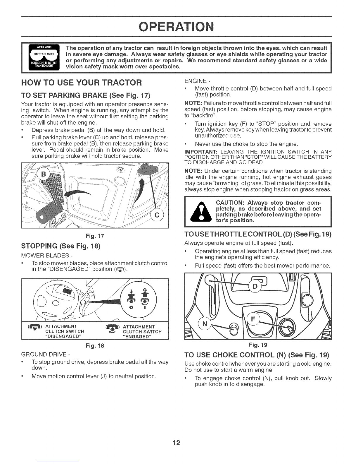
TO SET PARKING BRAKE (See Fig. 17)
Your tractor is equipped with an operator presence sens-
ing switch. When engine is running, any attempt by the
operator to leave the seat without first setting the parking
brake will shut off the engine.
Depress brake pedal (B) all the way down and hold.
o Pull parking brake lever (C) up and hold, release pres-
sure from brake pedal (B), then remeaseparking brake
lever. Pedal should remain in brake position. Make
sure parking brake will hold tractor secure.
Fig. 17
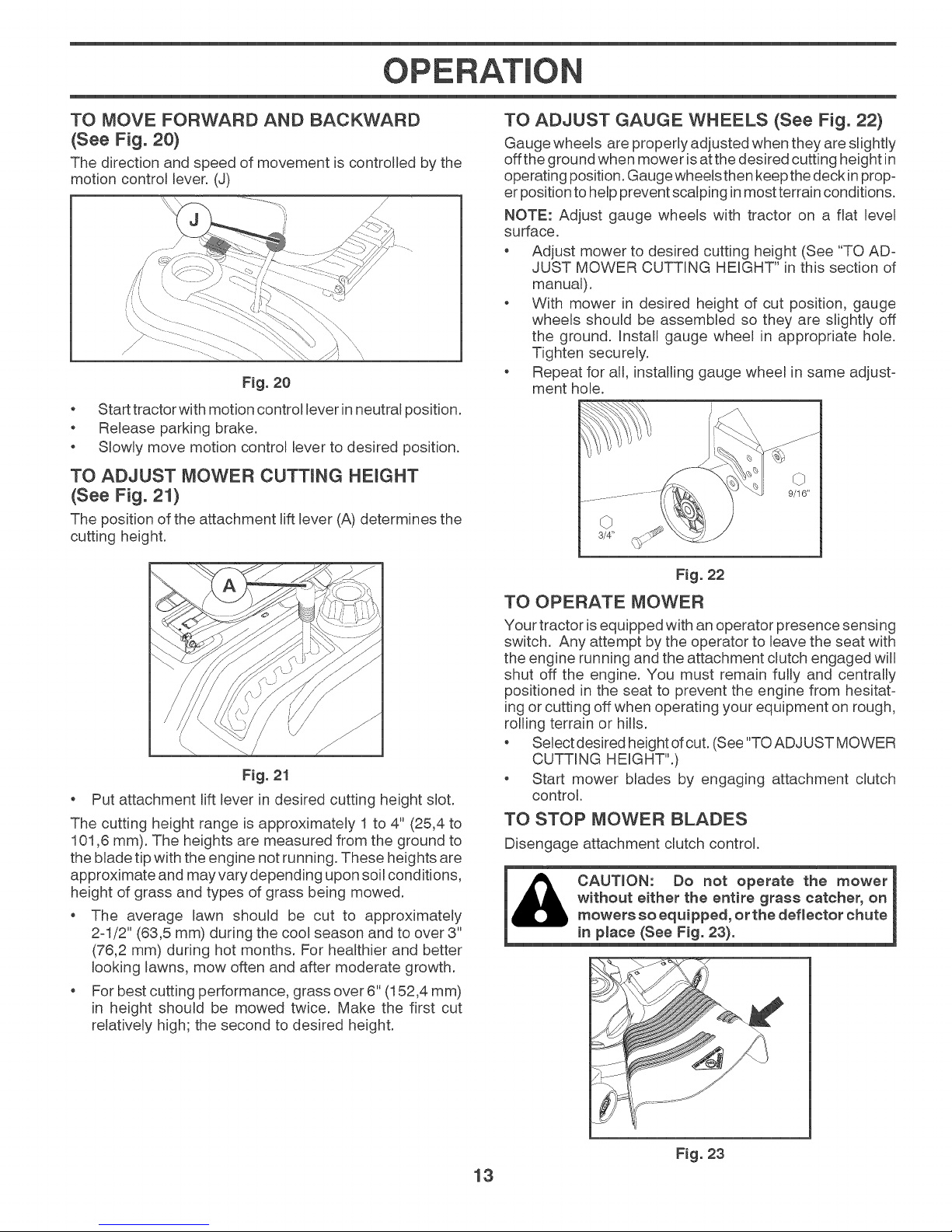
STOPPING (See Fig. 18}
MOWER BLADES -
Tostop mower blades, place attachment clutch control
in the "DISENGAGED" position (t_).
ENGINE -
Move throttle control (D) between half and fuji speed
(fast) position.
NOTE: Failure to move throttle control between half and full
speed (fast) position, before stopping, may cause engine
to "backfire".
Turn ignition key (F) to "STOP" position and remove
key.Always remove keywhen leaving tractor to prevent
unauthorized use.
Never use the choke to stop the engine.
IMPORTANT: LEAVING THE IGNITION SWITCH IN ANY
POSITION OTHER THAN "STOP" WILL CAUSE THE BATTERY
TO DISCHARGE AND GO DEAD.
NOTE: Under certain conditions when tractor is standing
idle with the engine running, hot engine exhaust gases
may cause "browning" of grass. To eliminate this possibility,
always stop engine when stopping tractor on grass areas.
pletely, as described above, and set
CAUTION: Always stop tractor com-
parking brake before leaving the opera°
tot's position.
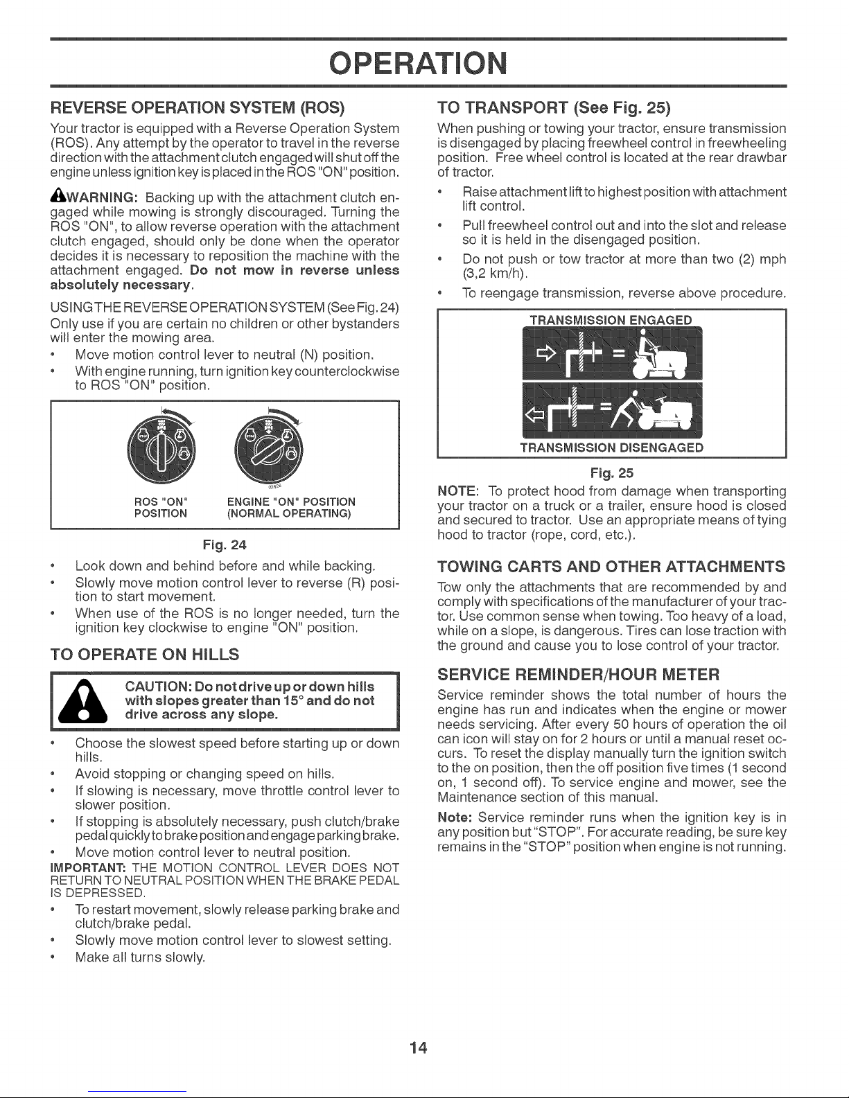
TO USE TH ROTTLE CONTROL (D) (See Fig. 19)
Always operate engine at fuji speed (fast).
, Operating engine at less than fuji speed (fast) reduces
the engine's operating efficiency.
, Fuji speed (fast) offers the best mower performance.
(_) ATTACHMENT
CLUTCH SWITCH
"DISENGAGED"
(_) ATTACHMENT
Fig. 18
GROUND DRIVE -
Tostop ground drive, depress brake pedal all the way
down.
Move motion control lever (J) to neutral position.
CLUTCH SWITCH
"ENGAGED"
Fig. 19
TO USE CHOKE CONTROL (N) (See Fig. 19)
Use choke control whenever you are starting a cold engine.
Do not use to start a warm engine.
o To engage choke control (N), pull knob out. Slowly
push knob in to disengage.
12
Page 13
OPERATION
TO MOVE FORWARD AND BACKWARD
(See Fig. 20}
The direction and speed of movement is controlled by the
motion control lever. (J)
\
Fig. 20
Start tractor with motion control lever in neutral position.
Release parking brake.
Slowly move motion control lever to desired position.
TO ADJUST MOWER CUTTING HEIGHT
(See Fig. 21)
The position of the attachment lift lever (A) determines the
cutting height.
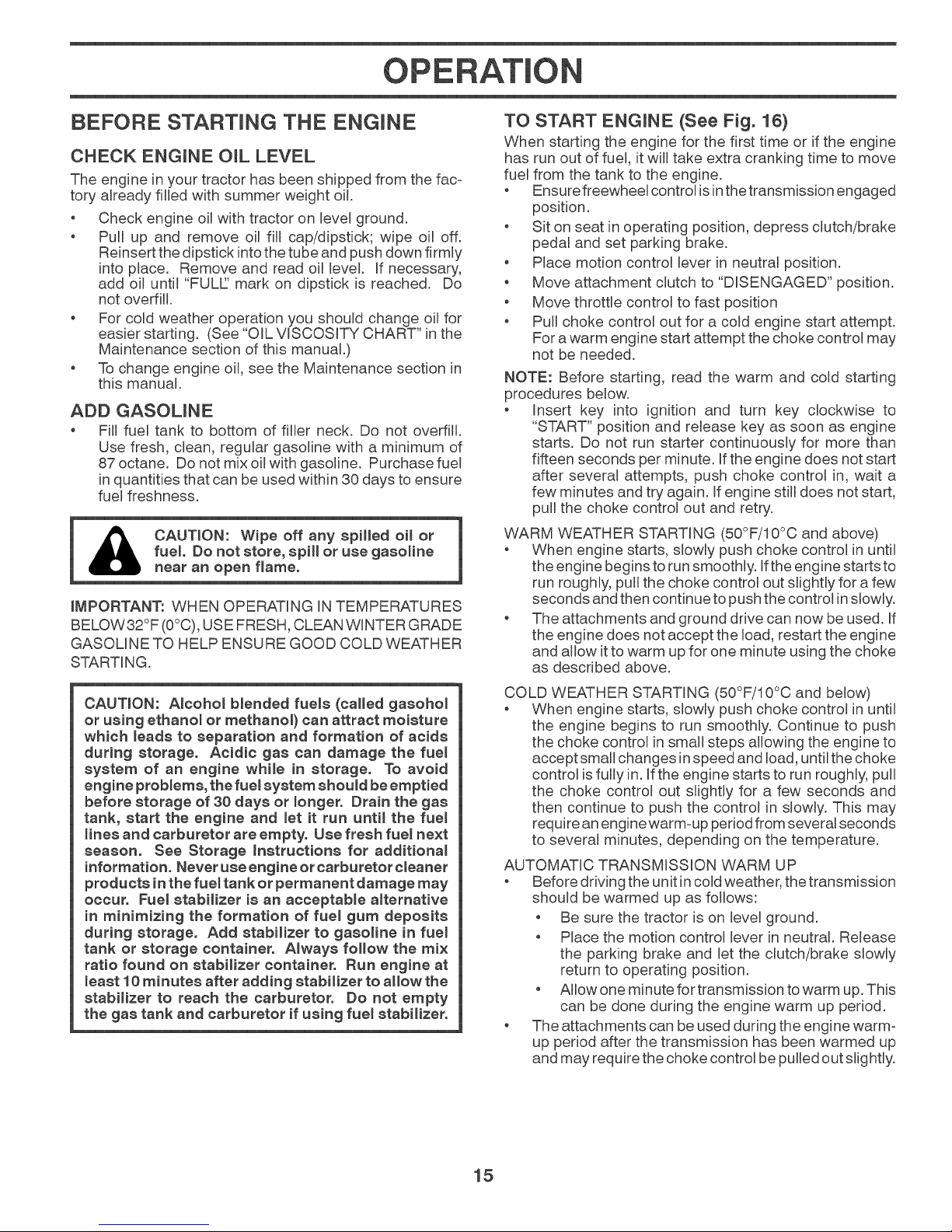
TO ADJUST GAUGE WHEELS (See Fig. 22)
Gauge wheels are properly adjusted when they are slightly
off the ground when mower is atthe desired cutting height in
operating position. Gauge wheels then keep thedeck inprop-
er position tohelp prevent scalping inmost terrain conditions.
NOTE: Adjust gauge wheels with tractor on a flat level
surface.
Adjust mower to desired cutting height (See "TO AD-
JUST MOWER CUTTING HEIGHT" in this section of
manual).
With mower in desired height of cut position, gauge
wheels should be assembled so they are slightly off
the ground. Install gauge wheel in appropriate hole.
Tighten securely.
Repeat for all, installing gauge wheel in same adjust-
ment hole.
3/4"
Fig. 21
Put attachment lift lever in desired cutting height slot.
The cutting height range is approximately 1 to 4" (25,4 to
101,6 mm). The heights are measured from the ground to
the blade tip with the engine not running. These heights are
approximate and may vary depending upon soil conditions,
height of grass and types of grass being mowed.
The average lawn should be cut to approximately
2-1/2" (63,5 mm) during the cool season and to over 3"
(76,2 mm) during hot months. For healthier and better
looking lawns, mow often and after moderate growth.
For best cutting performance, grass over 6" (152,4 mm)
in height should be mowed twice. Make the first cut
relatively high; the second to desired height.
Fig. 22
TO OPERATE MOWER
Your tractor isequipped with an operator presence sensing
switch. Any attempt by the operator to leave the seat with
the engine running and the attachment clutch engaged will
shut off the engine. You must remain fully and centrally
positioned in the seat to prevent the engine from hesitat-
ing or cutting off when operating your equipment on rough,
rolling terrain or hills.
Select desired height of cut. (See "TOADJUST MOWER
CUTTING HEIGHT".)
Start mower blades by engaging attachment clutch
control.
TO STOP MOWER BLADES
Disengage attachment clutch control.
without either the entire grass catcher, on
CAUTION: Do not operate the mower
mowers so equipped, or the deflector chute
in p_ace (See Fig. 23).
Fig. 23
13
Page 14
OPERATION
REVERSE OPERATION SYSTEM (ROS)
Your tractor is equipped with a Reverse Operation System
(RO%. Any attempt by the operator to travemin the reverse
direction with the attachment clutch engaged will shut off the
engine unless ignition key is placed inthe ROS "ON" position.
AI_WARNING: Backing up with the attachment clutch en-
gaged while mowing is strongly discouraged. Turning the
ROS "ON", to allow reverse operation with the attachment
clutch engaged, should only be done when the operator
decides it is necessary to reposition the machine with the
attachment engaged. Do not mow in reverse unless
absolutely necessary.
USINGTHE REVERSE OPERATION SYSTEM (See Fig. 24)
Only use ifyou are certain no children or other bystanders
will enter the mowing area.
Move motion control lever to neutral (N) position.
With engine running, turn ignition key counterclockwise
to ROS "ON" position.
ROS '"ON'"
PosmoN
Look down and behind before and while backing.
Slowly move motion control lever to reverse (R) posi-
tion to start movement.
When use of the ROS is no longer needed, turn the
ignition key clockwise to engine "ON" position.
ENGINE "ON" POSITION
(NORMAL OPERATING)
F_g. 24
TO OPERATE ON HILLS
[_lh CAUT_ON:Donotdriveupordownhills
, Choose the slowest speed before starting up or down
hills.
o Avoid stopping or changing speed on hills.
, If slowing is necessary, move throttle control lever to
slower position.
, If stopping is absolutemy necessary, push clutch/brake
pedal quickly tobrake position and engage parking brake.
, Move motion control lever to neutral position.
iMPORTANT: THE MOTION CONTROL LEVER DOES NOT
RETURNTO NEUTRALPOSITIONWHEN THE BRAKEPEDAL
IS DEPRESSED.
" Torestart movement, slowly release parking brake and
clutch/brake pedal.
, Slowly move motion control lever to slowest setting.
, Make all turns slowly.
with slopes greater than 15° and do not
drive across any smope.
TO TRANSPORT (See Fig. 25)
When pushing or towing your tractor, ensure transmission
is disengaged by placing freewheel control in freewheeling
position. Free wheel control is located at the rear drawbar
of tractor.
Raise attachment riftto highest position with attachment
lift control.
Pull freewheel control out and into the slot and release
so it is held in the disengaged position.
Do not push or tow tractor at more than two (2) mph
(3,2 km/h).
To reengage transmission, reverse above procedure.
TRANSMiSSiON ENGAGED
TRANSMiSSiON DISENGAGED
Fig. 25
NOTE: To protect hood from damage when transporting
your tractor on a truck or a trailer, ensure hood is closed
and secured to tractor. Use an appropriate means of tying
hood to tractor (rope, cord, etc.).
TOWING CARTS AND OTHER ATTACHMENTS
Tow only the attachments that are recommended by and
comply with specifications ofthe manufacturer of your trac-
tor. Use common sense when towing. Too heavy of a load,
while on a slope, is dangerous. Tires can lose traction with
the ground and cause you to lose control of your tractor.
SERVICE REMINDER/HOUR METER
Service reminder shows the total number of hours the
engine has run and indicates when the engine or mower
needs servicing. After every 50 hours of operation the oil
can icon will stay on for 2 hours or until a manual reset oc-
curs. To reset the display manually turn the ignition switch
to the on position, then the off position five times (1second
on, 1 second off). To service engine and mower, see the
Maintenance section of this manual.
Note: Service reminder runs when the ignition key is in
any position but "STOP". For accurate reading, besure key
remains inthe "STOP" position when engine is not running.
14
Page 15
OPERATION
BEFORE STARTING THE ENGmNE
CHECK ENGINE OIL LEVEL
The engine in your tractor has been shipped from the fac=
tory already filled with summer weight oil.
Check engine oil with tractor on level ground.
Pull up and remove oil fill cap/dipstick; wipe oil off.
Reinsert the dipstick into the tube and push down firmly
into place. Remove and read oil level. If necessary,
add oil until "FULL' mark on dipstick is reached. Do
not overfill.
For cold weather operation you should change oil for
easier starting. (See "OIL VISCOSITY CHART" in the
Maintenance section of this manual.)
To change engine oil, see the Maintenance section in
this manual.
ADD GASOLINE
* Fill fuel tank to bottom of filler neck. Do not overfill.
Use fresh, clean, regular gasoline with a minimum of
87 octane. Do not mix oil with gasoline. Purchase fuel
in quantities that can be used within 30 days to ensure
fuel freshness.
fuel Do not store, spill or use gasoline
CAUTION: Wipe off any spilled oil or
near an open flame.
iMPORTANT: WHEN OPERATING INTEMPERATURES
BELOW32°F (0°C), USE FRESH, CLEAN WINTER GRADE
GASOLINE TO HELP ENSURE GOOD COLD WEATHER
STARTING.
TO START ENGINE (See Fig. 16)
When starting the engine for the first time or if the engine
has run out of fuel, it will take extra cranking time to move
fuel from the tank to the engine.
Ensure freewheel control is inthe transmission engaged
position.
Sit on seat in operating position, depress clutch/brake
pedal and set parking brake.
Place motion control lever in neutral position.
Move attachment clutch to "DISENGAGED" position.
Move throttle control to fast position
Pull choke control out for a cold engine start attempt.
For a warm engine start attempt the choke control may
not be needed.
NOTE: Before starting, read the warm and cold starting
procedures bemow.
Insert key into ignition and turn key clockwise to
"START" position and release key as soon as engine
starts. Do not run starter continuously for more than
fifteen seconds per minute. If the engine does not start
after several attempts, push choke control in, wait a
few minutes and try again. If engine still does not start,
pull the choke control out and retry.
WARM WEATHER STARTING (50°F/10°C and above)
When engine starts, slowly push choke control in until
the engine begins to run smoothly. Ifthe engine starts to
run roughly, pull the choke control out slightly for afew
seconds and then continue to push the control inslowly.
The attachments and ground drive can now be used. If
the engine does not accept the load, restart the engine
and allow itto warm upfor one minute using the choke
as described above.
CAUTmON: A_cohoi bmended fuels (called gasohol
or using ethano_ or methanol} can attract moisture
which _eads to separation and formation of acids
during storage. Acidic gas can damage the fue_
system of an engine whime in storage. To avoid
engine problems, the fuemsystem should beemptied
before storage of 30 days or Jonger. Drain the gas
tank, start the engine and _et it run untim the fuel
Hnes and carburetor are empty. Use fresh fue_ next
season. See Storage hstructions for additional
information. Never use engine or carburetor cleaner
products in the fuel tank or permanent damage may
occur. Fuel stabilizer is an acceptable alternative
in minimizing the formation of fue_ gum deposits
during storage. Add stabilizer to gasoline in fue_
tank or storage container. Always follow the mix
ratio found on stabilizer container. Run engine at
_east 10 minutes after adding stabilizer to allow the
stabilizer to reach the carburetor. Do not empty
the gas tank and carburetor if using fue_ stabilizer.
COLD WEATHER STARTING (50°F/10°C and bemow)
When engine starts, slowly push choke control in until
the engine begins to run smoothly. Continue to push
the choke control in small steps allowing the engine to
accept small changes in speed and load, until the choke
control is fully in. Ifthe engine starts to run roughly, pull
the choke control out slightly for a few seconds and
then continue to push the control in slowly. This may
require anengine warm=up period from several seconds
to several minutes, depending on the temperature.
AUTOMATIC TRANSMISSION WARM UP
Before driving the unit incold weather, the transmission
should be warmed up as follows:
Be sure the tractor is on levemground.
Place the motion control lever in neutral. Release
the parking brake and let the clutch/brake slowly
return to operating position.
Allow one minute for transmission towarm up. This
can be done during the engine warm up period.
The attachments can be used during the engine warm-
up period after the transmission has been warmed up
and may require the choke control be pulled out slightly.
15
Page 16
OPERATION
PURGE TRANSM_SSION
1_ CAUTION: Never engage or disengage free- 1
To ensure proper operation and performance, it is recom-
mended that the transmission be purged before operating
tractor for the first time. This procedure will remove any
trapped air inside the transmission wNch may have devel=
oped during shipping of your tractor.
iMPORTANT: SHOULD YOUR TRANSMISSION REQUIRE
REMOVAL FOR SERVICE OR REPLACEMENT,iT SHOULD
BE PURGEDAFTER REINSTALLATIONBEFOREOPERATING
THE TRACTOR.
1. Place tractor safely on a level surface =that is clear
2. Disengage transmission by placing freewheel control
3. Sitting in the tractor seat, start engine. After the en=
i CAUTmON: At anytime, during etep 4, there
_may be movement of the drive wheels.
4. Move motion control lever to full forward position and
5. Move motion control lever to neutral position. Shut- off
6. Engage transmission by placing freewheem control in
7. Sitting inthe tractor seat, start engine. After the engine
8. Slowly move motion control lever forward, after the
Your transmission is now purged and now ready for normal
operation.
whee_ _ever while the engine ks running.
and open =with engine off and parking brake set.
in disengaged position. (See "TO TRANSPORT" in
this section of manual.)
gine is running, move throttle control to slow position.
Disengage parking brake
hold for five (5) seconds. Move lever to full reverse
position and hold for five (5) seconds. Repeat this
procedure three (3) times.
engine and set parking brake.
engaged position. (See "TO TRANSPORT" in this
section of manual.)
is running, move throttle control to half (1/2) speed.
With motion control lever in neutral position, slowly
disengage clutch/brake pedal.
tractor moves approximatelyfive (5) feet (1,5 m), slowly
move motion control lever to reverse position. After the
tractor moves approximately five (5) feet (1,5 m) return
the motion control lever to the neutral position. Repeat
this procedure with the motion control lever three (3)
times.
MOWING TiPS
, DO NOT use tire chains when the mower housing is
attached to tractor.
!
, Mower should be properly leveled for best mowing
performance. See "TO LEVEL MOWER HOUSING"
in the Service and Adjustments section of this manual.
The left hand side ofmower should be used for trimming.
Drive so that clippings are discharged onto the area
that has been cut. Have the cut area to the right of
the tractor. This will result in a more even distribution
of clippings and more uniform cutting.
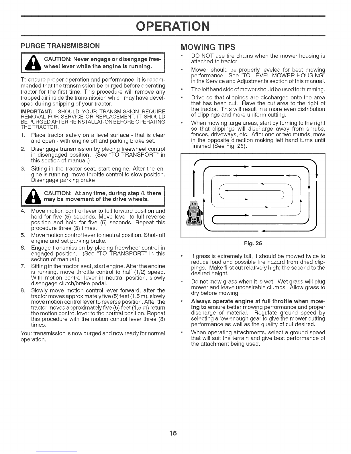
When mowing large areas, start by turning to the right
so that clippings will discharge away from shrubs,
fences, driveways, etc. After one or two rounds, mow
in the opposite direction making left hand turns until
finished (See Fig. 26).
(
Fig. 26
If grass is extremely tall, it should be mowed twice to
reduce load and possible fire hazard from dried clip-
pings. Make first cut relatively high; the second to the
desired height.
Do not mow grass when it is wet. Wet grass will plug
mower and leave undesirable clumps. Allow grass to
dry before mowing.
. Always operate engine at full throttle when mow°
ing to ensure better mowing performance and proper
discharge of material. Regulate ground speed by
selecting a low enough gear togive the mower cutting
performance as well as the quality of cut desired.
, When operating attachments, select a ground speed
that will suit the terrain and give best performance of
the attachment being used.
16
Page 17
M NTENANCE
Check Brake Operation
Check Tire Pressure
R_ Check Operator Presence & ROS Systems
A Check for Loose Fasteners
C ChecWReplace Mower Blades
T Lubrication Chart
(} Check Battery Level
R Clean Battery and Terminals
Clean Debris Off Steering Plate
Check Transaxle Cooling
Check Mower Levelness
Check V-Beks
Check Engine Oil Level
Change Engine Oil (models with oil filter)
Change Engine OiH(models without oiHfiHter)
Clean Air Filter
G Clean Air Screen
Inspect Muffler/Spark Arrester
N Replace Oil Filter(tf equipped)
Clean Engine Cooling Fins
Replace Spark Plug
RepHace Air FiHter Paper Cartridge
Replace Fuel Filter
1 - Change more often when operating under a heavy load or in high ambient temperatures.
2 - Service more often when operating in dirty or dusty conditions
BEFORE
EACH
USE
.J
EVERY
8
HOURS
EVERY
25
HOURS
EVERY
50
HOURS
v"
_#3
_1 _2
_1 _2
t!2
J
3 - Replace blades more often when mowing in sandy soil.
4 - Not required if equipped with maintenance-free battery.
EVERY
100
HOURS
EVERY
SEASON
J
_,2
5 - See Cleaning in Maintenance Section.
BEFORE
STORAGE
J
J
v'
GENERAL RECOMMENDATIONS
The warranty on this tractor does not cover items that have
been subjected to operator abuse or negligence. To receive
full value from the warranty, operator must maintain tractor
as instructed in this manual.
Some adjustments will need to be made periodically to
properly maintain your tractor.
At least once a season, check to see if you should make
any of the adjustments described in the Service and
Adjustments section of this manual.
At least once a year you should replace the spark plug,
clean or replace air filter, and check blades and belts
for wear. A new spark plug and clean air filter ensure
proper air-fuel mixture and help your engine run better
and last longer.
BEFORE EACH USE
Check engine oil level.
o Check brake operation.
o Check tire pressure.
o Check operator presence and ROS systems for proper
operation.
Check for loose fasteners.
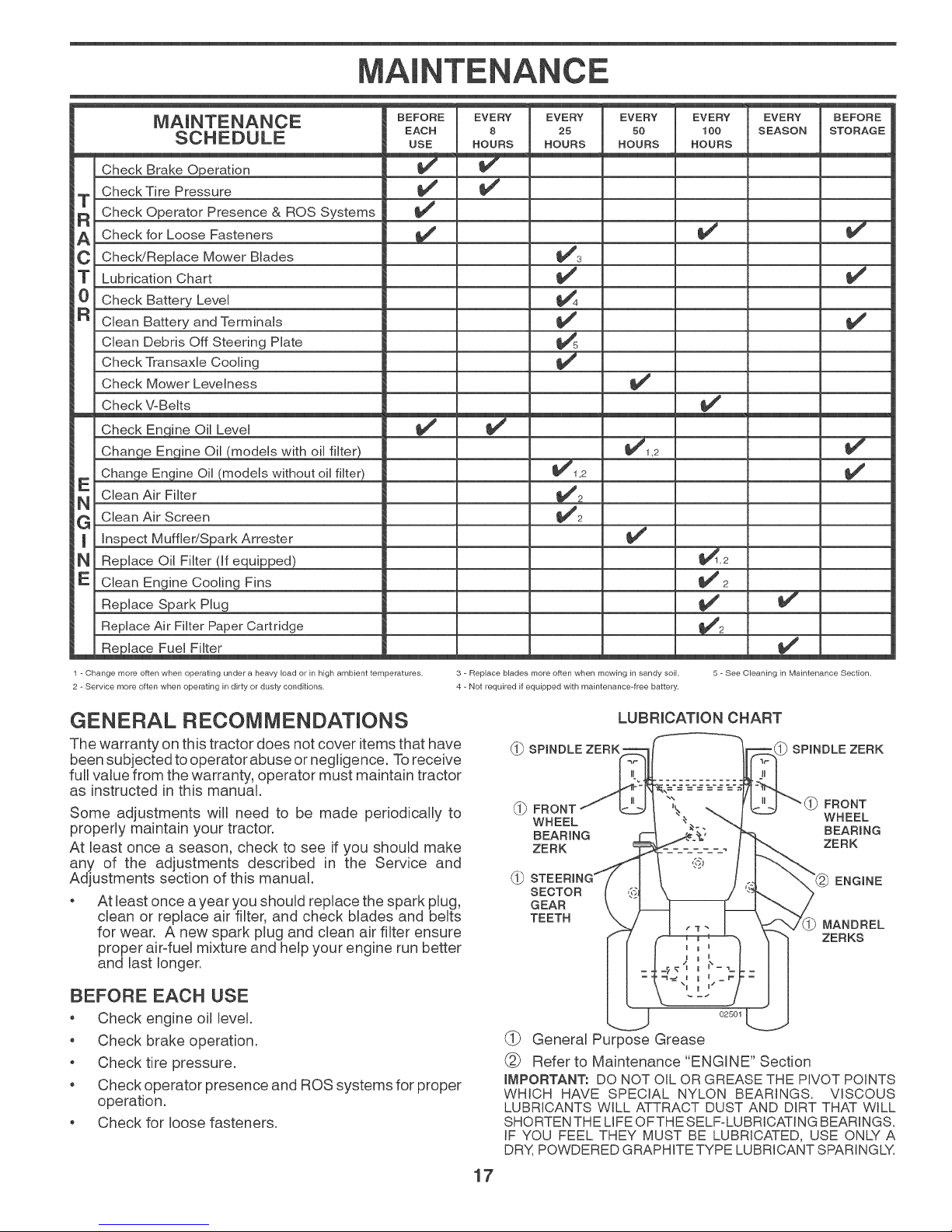
LUBRmCATLONCHART
_-_ SPINDLE ZERK _ SPINDLE ZERK
_-_ FRONT FRONT
WHEEL WHEEL
BEARING BEARING
ZERK ZERK
0b
SECTOR
GEAR
TEETH
02501
(_ General Purpose Grease
Refer to Maintenance "ENGINE" Section
IMPORTANT: DO NOT OIL OR GREASE THE PIVOT POINTS
WHICH HAVE SPECIAL NYLON BEARINGS. VISCOUS
LUBRICANTS WILL ATTRACT DUST AND DIRT THAT WILL
SHORTEN THE LIFE OFTHE SELF-LUBRICATING BEARINGS.
IF YOU FEEL THEY MUST BE LUBRICATED, USE ONLY A
DRY, POWDERED GRAPHITE TYPE LUBRICANT SPARINGLY.
17
ENGINE
MANDREL
ZERKS
Page 18
MAINTENANCE
Always observe safety rules when performing any
maintenance.
BRAKE OPERATION
If tractor requires more than five (5) feet (1,5 m) to stop at
highest speed in highest gear on a level, dry concrete or
paved surface, then brake must be checked and adjusted.
(See "TO CHECK BRAKE" in the Service and Adjustments
section of this manual.
TIRES
Maintain proper aurpressure in all tires. (See the sides
of tires for proper PSI.)
Keep tires free of gasoline, oil, or insect control
chemicals wNch can harm rubber.
* Avoid stumps, stones, deep ruts, sharp objects and
other hazards that may cause tire damage.
NOTE: To seal tire punctures and prevent flat tires due
to slow leaks, tire sealant may be purchased from your
local parts dealer. Tire sealant also prevents tire dry rot
and corrosion.
OPERATOR PRESENCE SYSTEM AND REVERSE
OPERATION SYSTEM (ROS) (See Fig. 27)
Be sure operator presence and reverse operation systems
are working properly. If your tractor does not function as
described, repair the problem immediately.
* The engine should not start unless the brake pedal is
fully depressed, and the attachment clutch control is
in the disengaged position.
CHECK OPERATOR PRESENCE SYSTEM
* When the engine isrunning, any attempt by the operator
to leave the seat without first setting the parking brake
should shut off the engine.
* When the engine is running and the attachment clutch
is engaged, any attempt by the operator to leave the
seat should shut off the engine.
* The attachment clutch should never operate unless
the operator is in the seat.
CHECK REVERSE OPERATION (ROS) SYSTEM
* When the engine is running with the ignition switch in
the engine "ON" position and the attachment clutch
engaged, any attempt by the operator to shift into
reverse should shut off the engine.
* When the engine is running with the ignition switch
in the ROS "ON" position and the attachment clutch
engaged, any attempt by the operator to shift into
reverse should NOT shut off the engine.
ROB "ON"
POSITION
ENGINE "ON" POSITION
(NORMAL OPERATING)
F_g. 27
BLADE CARE
Forbest results mower blades must be kept sharp. Replace
bent or damaged blades.
& CAUTNON: Use orflya replacement bladeap-
proved bythe manufacturer of your tractor.
Using a blade not approved by the manu°
facturer of your tractor is hazardous, could
damage your tractor and void your warranty.
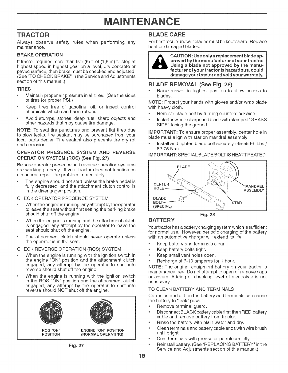
BLADE REMOVAL (See Fig. 28)
o Raise mower to highest position to allow access to
blades.
NOTE: Protect your hands with gloves and/or wrap blade
with heavy cloth.
o Remove blade bolt by turning counterclockwise.
* Install new or resharpened blade with stamped "GRASS
SIDE" facing the ground.
IMPORTANT: To ensure proper assembly, center hole in
blade must align with star on mandrel assembly.
* Install and tighten blade bolt securely (45%5 Ft. Lbs./
62=75 Nm).
IMPORTANT: SPECIAL BLADE BOLT ISHEATTREATED.
BLADE
CENTER
/
BLADE _.._
BOLT / _
(SPECIAL}
_ i MANDREL
i
ASSEMBLY
STAR
Fig. 28
Your tractor has a battery charging system which issufficient
for normal use. However, periodic charging of the battery
with an automotive charger will extend its life.
* Keep battery and terminals clean.
* Keep battery bolts tight.
* Keep small vent holes open.
* Recharge at 6=10 amperes for 1 hour.
NOTE: The original equipment battery on your tractor is
maintenance free. Do not attempt to open or remove caps
or covers. Adding or checking level of electrolyte is not
necessary.
TO CLEAN BATTERY AND TERMINALS
Corrosion and dirt on the battery and terminals can cause
the battery to "leak" power.
* Remove terminal guard.
* Disconnect BLACKbatterycablefirst then RED battery
cable and remove battery from tractor.
* Rinse the battery with plain water and dry.
* Clean terminals and battery cable ends with wire brush
until bright.
* Coat terminals with grease or petroleum jelly.
* Reinstall battery. (See "REPLACING BATTERY" in the
Service and Adjustments section of this manual.)
18
Page 19
lVi NTENANCE
TRANSAXLE MAINTENANCE
The transmission fan and cooling fins should be kept clean
to assure proper cooling.
Do not attempt to clean fan or transmission while engine
is running or while the transmission is hot. To prevent pos-
sible damage to seals, do not use high pressure water or
steam to clean transmission.
Inspect cooling fan to be sure fan blades are intact and
clean.
o Inspect coolingfins for dirt, grass clippings and other ma-
terials. To prevent damage to seals, do not use compre-
ssed air or high pressure sprayer to clean cooling fins.
TRANSAXLE PUMP FLUID
The transaxle was sealed at the factory and fluid mainte-
nance is not required for the life of the transaxle. Should
the transaxle ever leak or require servicing, contact your
nearest authorized service center/department.
Check V-belts for deterioration and wear after 100 hours
of operation and replace if necessary. The beretsare not
adjustable. Replace belts if they begin to slip from wear.
ENGINE
Only use high quality detergent oil rated with API service
classification SG-SL. Select the oirs SAE viscosity grade
according to your expected operating temperature.
SAE VISCOSITY GRADES
F -20 0 30 32 40 60 80 100
C -30 -10 1'0 20 30 4'0
TEMPERATURE RANGE ANTICIPATED BEFORE NEXT OIL CHANGE
Fig. 29
Change the oil after every 50 hours of operation or at least
once a year if the tractor isnot used for 50 hours in one year.
Check the crankcase oil level before starting the engine
and after each eight (8) hours of operation.
LOWER
DASH
COVER
TABS
Fig. 30
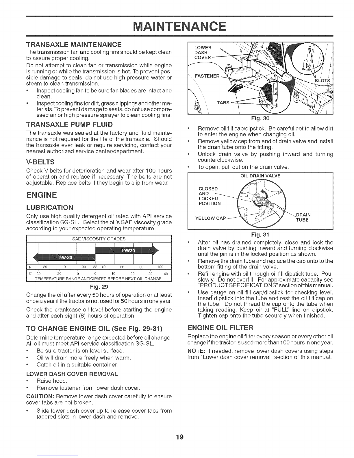
Remove oil fill cap/dipstick. Be careful not toallow dirt
to enter the engine when changing oil.
e
Remove yellow cap from end of drain valve and install
the drain tube onto the fitting.
o Unlock drain valve by pushing inward
and turning
counterclockwise.
To open, pull out on the drain valve.
OIL DRAIN VALVE
CLOSED
AND _ _,_._ ._
LOCKE
PoBmo,
,,o.._.
.uLLOW CAP/_',_. _>i;_j-"" .J "TUBE
Fig. 31
" After oil has drained completely, close and lock the
drain valve by pushing inward and turning clockwise
until the pin is in the locked position as shown.
, Remove the drain tube and replace the cap onto to the
bottom fitting of the drain valve.
, Refill engine with oil through oil fill dipstick tube. Pour
slowly. Do not overfill. For approximate capacity see
"PRODUCT SPECiFiCATiONS" section ofthis manual.
Use gauge on oil fill cap/dipstick for checking level.
insert dipstick into the tube and rest the oil fill cap on
the tube. Do not thread the cap onto the tube when
taking reading. Keep oil at "FULL:.' line on dipstick.
Tighten cap onto the tube securely when finished.
TO CHANGE ENGINE OIL (See Fig. 29-31)
Determine temperature range expected before oil change.
All oil must meet API service classification SG-SL.
Be sure tractor is on level surface.
Oil will drain more freely when warm.
Catch oil in a suitable container.
LOWER DASH COVER REMOVAL
Raise hood.
Remove fastener from lower dash cover.
CAUTION: Remove lower dash cover carefully to ensure
cover tabs are not broken.
Slide lower dash cover up to release cover tabs from
tapered slots in lower dash and remove.
ENGINE OiL FILTER
Replace the engine oil filter every season or every other oil
change ifthe tractor isused more than 100hours inone year.
NOTE: If needed, remove lower dash covers using steps
from "Lower dash cover removal" section of this manual.
19
Page 20
MAINTENANCE
AIR FILTER
Your engine will not run properly using a dirty air filter.
Service air cleaner more often under dusty conditions.
CLEAN AIR SCREEN
The air screen is over the air intake blower located on top
of engine. The air screen must be kept free of dirt and
chaff to prevent engine damage from overheating. Clean
with a wire brush or compressed air to remove dirt and
stubborn dried gum fibers.
ENGINE COOLING SYSTEM
To ensure proper cooling, make sure the grass screen,
cooling fins, and other external surfaces of the engine are
kept clean at all times.
Every 100 hours of operation (more often under extremely
dusty, dirty conditions), remove the blower housing and
other cooling shrouds. Clean the cooling fins and external
surfaces as necessary. Ensure the cooling shrouds are
reinstalled.
NOTE: Operating the engine with a blocked grass screen,
dirty orplugged cooling fins, and/or cooling shrouds removed
will cause engine damage due to overheating.
inspect and replace corroded muffler and spark arrester (if
equipped) as it could create a fire hazard and/or damage.
SPARK PLUGS
Replace spark plugs at the beginning of each mowing
season or after every 100 hours of operation, whichever
occurs first. Spark plug type and gap setting are shown in
"PRODUCT SPECIFICATIONS" section of this manual.
IN-LINE FUEL FILTER (See Fig. 32)
The fuel filter should be replaced once each season. Iffuem
filter becomes clogged, obstructing fuel flow to carburetor,
replacement is required.
* With engine cool, remove filter andplug fuemlinesections.
* Place new fuel filter in position in fuel line with arrow
pointing towards carburetor.
* Be sure there are no fuel line leaks and clamps are
properly positioned.
* Immediately wipe up any spilled gasoline.
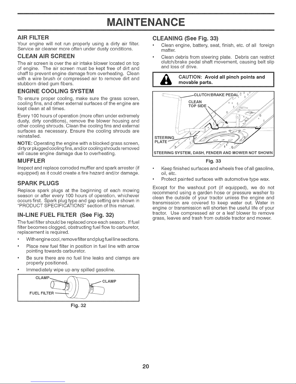
CLEANING (See Fig. 33}
* Clean engine, battery, seat, finish, etc. of all foreign
matter.
* Clean debris from steering plate. Debris can restrict
clutch/brake pedal shaft movement, causing belt slip
and loss of drive.
_ CAUTION: Avoid all pinch points and 1
STEER
PLATE __
STEERING SYSTEN, DASH, FENDER AND NOWER NOT SHOWN
* Keep finished surfaces and wheels free of all gasoline,
oil, etc.
* Protect painted surfaces with automotive type wax.
Except for the washout port (if equipped), we do not
recommend using a garden hose or pressure washer to
clean the outside of your tractor unless the engine and
transmission are covered to keep water out. Water in
engine or transmission will shorten the useful life of your
tractor. Use compressed air or a leaf blower to remove
grass, leaves and trash from outside tractor and mower.
movable parts.
i,,'i,i" TOP SIDE_ _ _
i,)
Fig. 33
FUEL FILTER
Fig. 32
2O
Page 21
M NTENANCE
DECK WASHOUT PORT (See Fig. 34)
Your tractor's deck is equipped with a washout port as part
of its deck wash system. It should be utilized after each use.
1. Drive the tractor to a level, clear spot on your lawn, near
enough to awater spigot for your garden hose to reach.
IMPORTANT: Make certain the tractor's discharge chute is
directed AWAY from your house, garage, parked cars, etc.
Remove bagger chute or mulch cover if attached.
2. Make sure the attachment clutch control is in the
"DISENGAGED" position, set the parking brake, and
stop the engine.
3. Thread the nozzle adapter (packaged with your tractor's
Operator's Manual) onto the end of your garden hose.
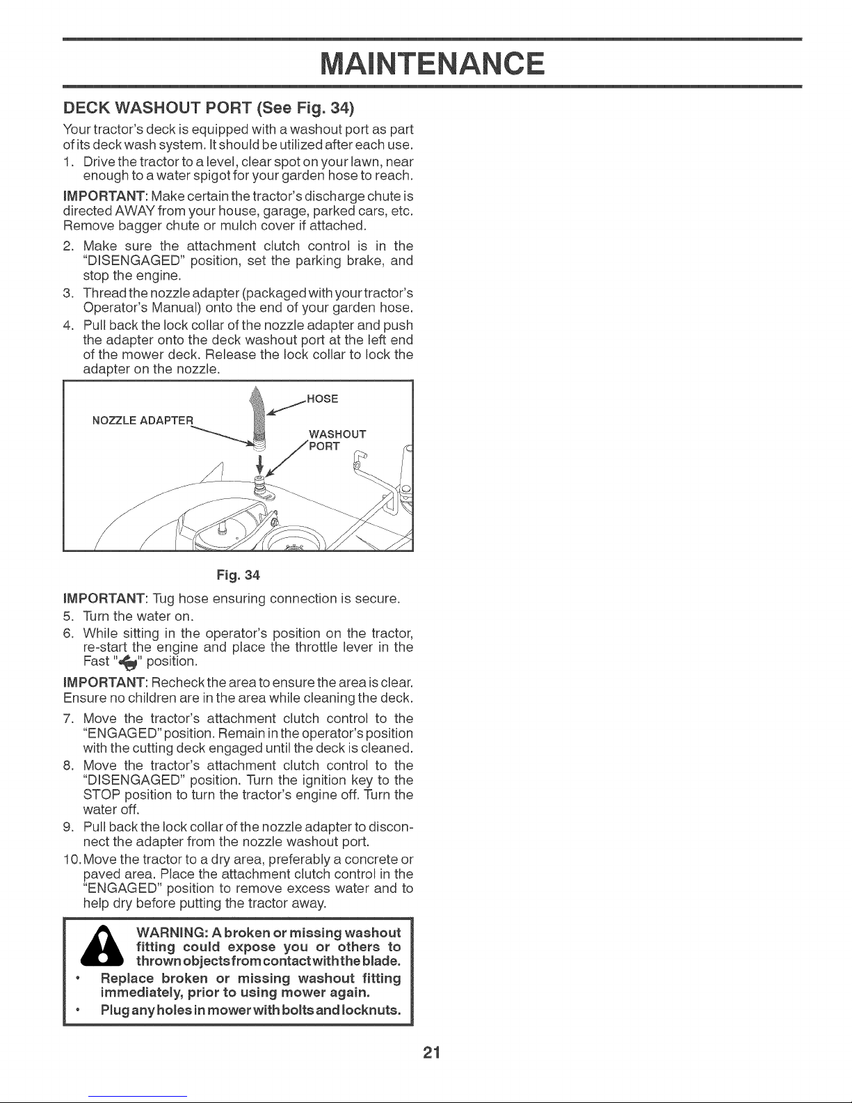
4. Pull back the lock collar of the nozzle adapter and push
the adapter onto the deck washout port at the left end
of the mower deck. Release the lock collar to lock the
adapter on the nozzle.
/HOSE
NOZZLE ADAPTER _
WASHOUT
F_g.34
IMPORTANT: Tug hose ensuring connection is secure.
5. Turn the water on.
6. While sitting in the operator's position on the tractor,
re-start the engine and place the throttle lever in the
Fast "_" position.
LMPORTANT: Recheck the area to ensure the area isclear.
Ensure no children are in the area while cleaning the deck.
7. Move the tractor's attachment clutch control to the
"ENGAGED" position. Remain inthe operator's position
with the cutting deck engaged until the deck is cleaned.
8. Move the tractor's attachment clutch control to the
"DISENGAGED" position. Turn the ignition key to the
STOP position to turn the tractor's engine off. Turn the
water off.
9. Pull back the lock collar of the nozzle adapter to discon-
nect the adapter from the nozzle washout port.
10.Move the tractor to a dry area, preferably a concrete or
paved area. Place the attachment clutch control in the
"ENGAGED" position to remove excess water and to
help dry before putting the tractor away.
fitting could expose you or others to
WARNING: A broken or missing washout
thrown objects from contact withthe blade.
, Replace broken or missing washout fitting
immediately, prior to using mower again.
• Plug any holes in mower with bolts and Iooknuts.
21
Page 22

SERVICE AND ADJUSTMENTS
& WARNING: TO AVOID SERIOUS iNJURY, BEFORE PERFORMING ANY SERVICE OR ADJUSTMENTS:
TO REMOVE MOWER (See Fig. 35)
Place attachment clutch in "DISENGAGED" position.
Lower attachment lift to its lowest position.
Disengage belt tension rod (K) from lock bracket (L).
i _ CAUTION: Belt tension rod is spring 1
* Remove mower belt from electric clutch pulley (M).
o Disconnect front lira (E) from mower - remove retainer
spring and washer.
Go toeitherside ofmower anddisconnect mowersuspen=
sion arm (A) from chassis and rear lift link (C) from rear
mower bracket (D)-remove retainersprings and washers.
Go to other side of mower and disconnect the suspen=
sion arm and rear lift link.
From right side of mower, disconnect anti=sway bar (S)
from right rear mower bracket (D) =remove retainer
spring and washer and pull mower toward you until the
bar falls from the hole in bracket.
, Turn tractor steering wheel to the left as far as itwill go.
Slide mower out from under right side of tractor.
TO INSTALL MOWER
Follow procedure described in "INSTALL MOWER AND
DRIVE BELT" in the Assembly section of this manual.
* Depress brake pedal fully and set parking brake.
* P_ace motion control _ever in neutral position.
* P_ace attachment clutch in "DISENGAGED" position.
* Turn ignition key to "STOP" and remove key.
* Make sure the blades and all moving parts have completely stopped.
* Disconnect spark p_ug wire from spark p_ug and p_ace wire where it cannot come in contact with p_ug.
TO REPLACE MOWER BLADE DRIVE BELT
(See Fig. 36)
MOWER DRIVE BELT REMOVAL
o Park tractor on a level surface. Engage parking brake.
o Lower attachment lift lever to its lowest position.
_oaded. Nave a tight grip on rodand
re_eaee elowmy.
CAUTION: After rear lift linke are diecononetted, the attachment lift lever win be
spring loaded. Have a tight grip on lift
lever when changing position of the meyer.
o Disengage belt tension rod (K) from lock bracket (L).
[ & CAUTnON: Beltteneion rod isspring loaded. 1
o Remove screws (P) from mandrel covers (Q) and
o Remove anydirt or grass clippingswhich may have accu-
, Remove beretfrom electric clutch pulley (M), both man-
MOWER DRIVE BELT INSTALLATION
, Install belt around all mandrel pulleys (R) and around
o Install belt onto electric clutch pulley (M).
iMPORTANT." Check belt for proper routing in all mower
pulley grooves.
o Reassemble mandrel covers (Q). Securely tighten all
, Engage berettension rod (K) on locking bracket (L).
I ,_ CAUTION:Belttensionrodieepringloaded.
Have a firm grip on rod and re_eaee slowly.
remove covers.
mulated around mandrels andentire upper deck surface.
drel pulleys (R) and all idler pulleys (V).
idler pulleys (V) as shown.
screws.
Have a firm grip onrod and release slowly.
Raise attachment lift lever to highest position.
Fig. 35
22
Page 23

SERVICE AND ADJUSTMENTS
TO LEVEL MOWER
Ensure tires are properly inflated to the PSI shown on tires.
If tires are over or under inflated, it may affect the appear-
ance of your lawn and lead you to think the mower is not
adjusted properly.
VISUAL SIDE-TO-SIDE ADJUSTMENT (See Fig. 37)
With all tires properly inflated and if your lawn appears
unevenly cut, determine wNch side of mower is cutting
lower.
NOTE: As desired, you can raise the low side of mower
or lower the high side.
Go to side of mower you wish to adjust.
With a3/4" or adjustable wrench, turn lift link adjustment
nut (A) to the left to lower the mower, or, to the right to
raise the mower.
TURN NUT RIGHT
TO RAISE MOWER
Fig. 37
NOTE: Each full turn of adjustment nut will change mower
height about 3/16" (4,7 mm).
Test your adjustment by mowing some uncut grass and
visually checking the appearance. Readjust, if neces-
sary, until you are satisfied with the results.
PRECISION SIDE-TO-SIDE ADJUSTMENT (See Fig. 38)
With all tires properly inflated, park tractor on level
ground or driveway.
TURN NUT LEFT
TO LOWER MOWER
Recheck measurements, adjust if necessary until both
sides are equal.
FRONT-TO-BACK ADJUSTMENT (See Figs. 39 & 40)
iMPORTANT: Deck must be level side-to-side.
To obtain the best cutting results, the mower blades should
be adjusted so the front tip is 1/8" to 1/2" (3,1 to 12,7 mm)
lower than the rear tip when the mower is in its highest
_osition.
your hands with gtoves and/or wrap
CAUTION: Blades are sharp. Protect
blade with heavy cmoth.
e
Raise mower to highest position.
e
Position any blade so the tip is pointing straightforward.
Measure distance (B) to the ground at front and rear tip
of the blade.
Fig. 39
If front tip of blade is not 1/8" to 1/2" (3,1 to 12,7 mm)
lower than the rear tip, go to the front of tractor.
With an 11/16" or adjustable wrench, loosen jam nut A
several turns to clear adjustment nut B.
With a 3/4" or adjustable wrench, turn front link adjust-
ment nut (B) clockwise (F_)(tighten) to raise the front of
mower, or, counterclockwise (_) (loosen) to lower the
front mower.
your hands with gloves and/or wrap
CAUTION: Blades are sharp. Protect
blade with heavy c_oth.
Raise mower to its highest position.
, At both sides of mower, position blade at side and mea-
sure the distance (A) from bottom edge of blade to the
ground. The distance should be the same on both sides.
, If adjustment is necessary, see steps in Visual Adjust-
ment instructions above.
Fig. 38
TIGHTEN ADJUST LOOSEN ADJUST
NUT "g" TO NUT "B" TO
RAISE MOWER LOWER MOWER
LOOSEN JAM NUT "A" FIRST
F_g. 40
NOTE: Each full turn of the adjustment nut will change
mower height about 1/8" (3,1 mm).
Recheck measurements, adjust if necessary until front
tip of blade is 1/8 to 1/2" (3,1 to 12,7 mm) lower than
the rear tip.
Hold adjustment nut in position with wrench and tighten
jam nut securely against adjustment nut.
23
Page 24

SERVICE AND ADJUSTMENTS
TO REPLACE MOTION DR_VE BELT
(See Fig. 41)
Park the tractor on levemsurface. Engage parking brake.
For assistance, there is a belt installation guide decal on
bottom side of left footrest.
BELT REMOVAL -
1. Remove mower (See "TO REMOVE MOWER" section
in this manual).
NOTE: Observe entire motion drive belt and position of all
belt guides and keepers.
2. Disconnect clutch wire harness (A).
3. Remove anti-rotation link (B) on right side of tractor.
4. Remove beltfromstationaryidler (C) andclutching idler (D).
5. Remove beretfrom centerspan idler (E).
6. Pull beretslack toward rear of tractor. Carefully remove
belt upwards from transmission input pulley and over
cooling fan blades (F).
7. Remove belt downward from engine pulley and around
electric clutch (G).
8. Slide belt toward rear of tractor, off the steering plate
(H) and remove from tractor.
BELT INSTALLATION -
1. Install new belt from tractor rear to front, over the steer-
ing plate (H) and above clutch brake pedal shaft (J).
2. Pull belt toward front of tractor and roll belt around
electric clutch and onto engine pulley (G).
3. Pull belt toward rear of tractor. Carefully work belt down
around transmission cooling fan and onto the input puF
ley (F). Be sure belt is inside the belt keeper.
4. Install belt on centerspan idler (E).
5. Install belt through stationary idler (C) and clutching
idler (D).
6. Reinstall anti-rotation link (B) on right side of tractor.
Tighten securely.
7. Reconnect clutch harness (A).
8. Make sure belt is in all pulley grooves and inside all belt
guides and keepers.
9. Install mower (See "TO INSTALL MOWER" section in
this manual).
TO CHECK BRAKE
If tractor requires more than five (5) feet (1,5 m) to stop at
highest speed in highest gear on a levem,dry concrete or
paved surface, then brake must be serviced.
You may also check brake by:
1. Park tractor on a level, dry concrete or paved surface,
depress brake pedal all the way down and engage
parking brake.
.
Disengage transmission by placing freewheel control
in "transmission disengaged" position. Pull freewheel
control out and into the slot and release so it is held in
the disengaged position.
The rear wheels must lockand skid when you try to manually
push the tractor forward. If the rear wheemsrotate, then the
brake needs tobe serviced. Contact a qualified service center.
FRONT WHEEL TOEoiN/CAMBER
Your new tractor front wheel toe-in and camber isset at the
factory and is normal. The front wheel toe-in and camber
are not adjustable. If damage has occurred to affect the
factory set front wheel toe-in or camber, contact a qualified
service center.
TO REMOVE WHEEL (See Fig. 42)
Block up axle securely.
Remove axle cover, retaining ring and washers to allow
wheemremoval (rear wheel contains a square key - Do
not lose).
Repair tire and reassemble.
On rear wheels only: align grooves in rear wheel hub
and axle. Insert square key.
Replace washers and snap retaining ring securely in
axle groove.
Replace axle cover.
NOTE: Toseal tire punctures and prevent flat tires duetoslow
leaks, tire sealant may be purchased from your local parts
dealer. Tire sealant also prevents tire dry rot and corrosion.
RETAJMNG RiNG WASHERS
/
F_g. 41
AXLE
COVER
SQUARE KEY
(REAR WHEEL ONLY) _'
F_g.42
24
Page 25

SERVICE AND ADJUSTMENTS
TRANSAXLE MOTION CONTROL LEVER
NEUTRAL ADJUSTMENT (See Fig. 43)
The motion control lever has been preset at the factory
and adjustment should not be necessary,
Loosen adjustment bolt in front of the right rear wheel,
and lightly tighten.
Start engine and move motion control lever until tractor
does not move forward or backward.
Hold motion control leverinthat position and turn engine
off,
While holding motion control lever in place, loosen the
adjustment bolt.
Move motion control lever to the neutral (lock gate)
position.
Tighten adjustment bolt securely.
NOTE: If additional clearance is needed to get to adjust-
ment bolt, move mower deck height to the lowest position.
After above adjustment is made, if the tractor still creeps
forward or backward while motion control lever is in neutral
position, follow these steps:
Loosen the adjustment bolt.
Move motion control lever 1/4 to 1/2" (6.3 to 12.7 mm)
in the direction it is trying to creep.
Tighten adjustment bolt securely.
Start engine and test.
Iftractor still creeps, repeat above steps until satisfied.
MOTION CONTROL
NEUTRAL
LOCK
GATE
TO START ENGINE WITH A WEAK BATTERY
(See Fig. 44)
WARNING _teries generate exo
&
If your battery is too weak to start the engine, it should be
recharged. (See "BATTERY" in the Maintenance section
of this manual.)
If "jumper cables" are used for emergency starting, follow
this procedure:
IMPORTANT: YOUR TRACTOR IS EQUIPPED WITH A
12 VOLT SYSTEM. THE OTHER VEHICLE MUST ALSO
BE A 12VOLT SYSTEM. DO NOT USE YOUR TRACTOR
BATTERY TO START OTHER VEHICLES.
TO ATTACH JUMPER CABLES -
TO REMOVE CABLES, REVERSE ORDER -
plosi_a ks, flame and smok-
ing materials away from batteries, Always
wear eye protection when around batteries,
Connect one end of the RED cable to the POSITIVE
(+) terminal of each battery (A-B), taking care not to
short against tractor chassis.
Connect one end ofthe BLACK cable tothe NEGATIVE
(-) terminal (C) of fully charged battery.
Connect the other end of the BLACK cable (D) to good
chassis ground, away from fuel tank and battery.
BLACK cable first from chassis and then from the fully
charged battery.
RED cable last from both batteries.
ADJ USTMENT
BOLT
WEAK
OR DEAD
BATTERY
Pqrq
FULLY
CHARGED
BATTERY
F_g. 44
25
Page 26

SERVICE AND ADJUSTMENTS
REPLACING BATTERY (See Fig. 45)
WARNING: Do not short battery termio
rials by allowing a wrench or any other
object to contact both termina_e at the
same time. Before connecting battery,
remove metal bracelets, wristwatch
bands, rings, etc. Positive termina_
must be connected first to prevent
sparking from accidenta_ grounding.
Lift hood to raised position.
Remove terminal cover.
Disconnect BLACK battery cable then RED battery
cable and carefully remove battery from tractor.
Install new battery with terminals in same position as
old battery.
Reinstall terminal cover.
First connect RED battery cable to positive (+) battery
terminal with bolt and nut as shown. Tighten securely.
Connect BLACK grounding cable to negative (-) battery
terminal with remaining bolt and nut. Tighten securely
o Close hood.
NEGATIVE
TO REMOVE HOOD AND GRILL ASSEMBLY
(See Fig. 46)
Raise hood.
o Unsnap headlight wire connector.
o Stand in front of tractor. Grasp hood at sides, tilt toward
engine and lift off of tractor.
To replace, reverse above procedure.
HEADUGHT
W{RE
CONNECTOR
(BLACK)
POSITIVE
(RED)
CABLE
TO REPLACE HEADLIGHT BULB
Raise hood.
o Pull bulb holder out of the hole in the backside of the
grill.
o Replace bulb in helder and push bulb holder securely
back into the hole in the backside of the grill.
o Close hood.
INTERLOCKS AND RELAYS
Loose or damaged wiring may cause your tractor to run
poorly, stop running, or prevent it from starting.
o Check wiring.
TO REPLACE FUSE
Replace with 20 amp automotive-type plug-in fuse. The
fuse holder is located behind the dash.
F_g.46
TRANSMISSmON
REMOVAL/REPLACEMENT
Sheuld your transmission require removal for service or
replacement, it should be purged after reinstallation and
before operatingthetractor. See"PURGETRANSMISSION"
in the Operation section of this manual.
TO ADJUST THROTTLE CONTROL CABLE
The throttle control has been preset at the factory and
adjustment sheuld not be necessary. Ifadjustment is nec-
essary, see engine manual.
TO ADJUST CHOKE CONTROL
The choke control has been preset atthe factory and adjust-
ment should not be necessary. If adjustment is necessary,
see engine manual.
26
Page 27

STORAGE
Immediatemy prepare your tractor for storage at the end
of the season or if the tractor will not be used for 30 days
or more.
gasoline in the tank inside a building
_ WARNmNG: Never store the tractor with
Remove mowerfrom tractor forwinter storage. When mower
istobestored for a period oftime, clean itthoroughly, remove
all dirt, grease, leaves, etc. Store in a clean, dry area.
Clean entire tractor. (See "CLEANING" in the
Maintenance section of this manual.)
Inspect and replace belts, if necessary. (See beret
replacement instructions inthe Service and Adjustments
section of this manual.)
Lubricate as shown in the Maintenance section of this
manual.
Be sure that all nuts, bolts and screws are securely
fastened. Inspect moving parts for damage, breakage
and wear. Replace if necessary.
Touch up all rusted or chipped paint surfaces; sand
lightly before painting.
where fumes may reach an open flame
or spark. AHowthe engine to coo_ before
storing in any enclosure.
FUEL SYSTEM
IMPORTANT: IT IS IMPORTANTTO PREVENTGUM DEPOSITS
FROM FORMING IN ESSENTIAL FUELSYSTEM PARTS SUCH
AS CARBURETOR, FUEL FILTER, FUEL HOSE, OR TANK
DURING STORAGE. ALSO, EXPERIENCE INDICATES THAT
ALCOHOL BLENDED FUELS (CALLED GASOHOL OR USING
ETHANOL OR METHANOL) CAN ATTRACT MOISTURE WHICH
LEADS TO SEPARATION AND FORMATION OFACIDS DURING
STORAGE. ACIDIC GAS CAN DAMAGE THE FUEL SYSTEM
OF AN ENGINE WHILE IN STORAGE.
Empty the fuel tank by starting the engine and let it run
until the fuel lines and carburetor are empty.
Never use engine or carburetor cleaner products in
the fuel tank or permanent damage may occur.
Use fresh fuel next season.
NOTE: Fuel stabilizer is an acceptable alternative in
minimizing theformation offuel gum deposits during storage.
Add stabilizer to gasoline in fuel tank or storage container.
Always follow the mix ratio found on stabilizer container.
Run engine at least 10 minutes after adding stabilizer to
allow the stabilizer to reach the carburetor. Do not empty
the gas tank and carburetor if using fuel stabilizer.
ENGSNE OIL
Drain oil (with engine warm) and replace with clean engine
oil. (See "ENGINE" in the Maintenance section of this
manual.)
Fully charge the battery for storage.
After a period of time in storage, battery may require
recharging.
o To help prevent corrosion and power leakage during
long periods of storage, battery cables should be
disconnected and battery cleaned thoroughly. (See
"TO CLEAN BATTERY AND TERMINALS" in the
Maintenance section of this manual.)
After cleaning, leave cables disconnected and place
cables where they cannot come in contact with battery
terminals.
If battery is removed from tractor for storage, do not
store battery directly on concrete or damp surfaces.
If unit is equipped with battery indicator/charging
plug, an optional charging unit may be purchased and
connected to the unit to charge the battery during long
term storage. Inspect and clean the battery terminals
as needed prior to long term storage with charger
connected.
o Remove spark plug(s).
Pour one ounce (29.5 mL) of Oil through spark plug
hole(s) into cylinder(s).
Turn ignition key to "START" position for afew seconds
to distribute oil.
o Replace with new spark plug(s).
Do not store gasoline from one season to another.
Replace your gasoline can if your can starts to rust.
Rust and/or dirt in your gasoline will cause problems.
If possible, store your tractor indoors and cover it to
give protection from dust and dirt.
Cover your tractor with a suitable protective cover that
does not retain moisture. Do not use plastic. Plastic
cannot breathe which allows condensation to form and
will cause your tractor to rust.
IMPORTANT: NEVER COVER TRACTOR WHILE ENGINE
AND EXHAUST AREAS ARE STILL WARM.
27
Page 28

TROUBLESHOOTING
PROBLEM
Will not start
Hard to start
Engine will not turn
over
Engine clicks but
will not start
Loss of power
Excessive
vibration
CAUSE
1. Out of fuel.
2. Engine not "CHOKED" properly.
3. Engine flooded.
4. Bad spark plug.
5. Dirty air filter.
6. Dirty fuel filter.
7. Water in fuel.
8. Loose or damaged wiring.
9. Engine valves out of adjustment.
1. Dirty air filter.
2. Bad spark plug.
3. Weak or dead battery.
4. Dirty fuel filter.
5. Stale or dirty fuel.
6. Loose or damaged wiring.
7. Engine valves out of adjustment.
1. Brake pedal not depressed.
2. Attachment clutch is engaged.
3. Weak or dead battery.
4. Blown fuse.
5. Corroded battery terminals.
6. Loose or damaged wiring.
7. Faulty ignition switch.
8. Faulty solenoid or starter.
9. Faulty operator presence switch(es).
1. Weak or dead battery.
2. Corroded battery terminals.
3. Loose or damaged wiring.
4. Faulty solenoid or starter.
1,
Cutting too much grass/too fast.
2.
Throttle in "CHOKE" position.
3.
Build-up ofgrass, leaves, trash under mower.
4.
Dirty air filter.
5.
Low oil level/dirty oil.
6.
Faulty spark plug.
7.
Dirty fuel filter.
8.
Stale or dirty fuel.
9.
Water in fuel.
10. Spark plug wire loose.
11. Dirty engine air screen/fins.
12. Dirty/clogged muffler.
13. Loose or damaged wiring.
14. Engine valves out of adjustment.
1. Worn, bent or loose blade.
2. Bent blade mandrel.
3. Loose/damaged part(s).
CORRECTION
1. Fitl fue{tank.
2. See "TO START ENGINE" in Operation section.
3. Wait several minutes before attempting to start.
4. Replace spark plug.
5. Clean/replace air filter.
6. Replace fuel filter.
7. Empty fuel tank and carburetor, refill tank with fresh
gasoline and replace fuel filter.
8. Check all wiring.
9. Contact an authorized service center/department.
1. Clean/replace air filter.
2. Replace spark plug.
3. Recharge or replace battery.
4. Replace fuel filter.
5. Empty fuel tank and refill tank with fresh, clean gas.
6. Check all wiring.
7. Contact an authorized service center/department.
1. Depress brake pedal.
2. Disengage attachment clutch.
3. Recharge or replace battery.
4. Replace fuse.
5. Clean battery terminals.
6. Check all wiring.
7. Check/replace ignition switch.
8. Check/replace solenoid or starter.
9. Contact an authorized service center/department.
1. Recharge or replace battery.
2. Clean battery terminals.
3. Check all wiring.
4. Check/replace solenoid or starter.
1. Raise cutting height/reduce speed.
2. Adjust throttle control.
3. Clean underside of mower housing.
4. Clean/replace air filter.
5. Check oil level/change oil.
6. Clean and regap or change spark plug.
7. Replace fuel filter.
8. Empty fuel tank and refill tank with fresh, clean gas.
9. Empty fuel tank and carburetor, refill tank with fresh
gasoline and replace fuel filter.
10. Connect and tighten spark plug wire.
11. Clean engine air screen/fins.
12. Clean/replace muffler.
13. Check all wiring.
14. Contact an authorized service center/department.
1. Replace blade. Tighten blade bolt.
2. Replace blade mandrel.
3. Tighten loose part(s). Replace damaged parts.
28
Page 29

TROUBLESHOOTING
PROBLEM
Engine continues to
run when operator
leaves seat with
attachment clutch
engaged
Poorout-uneven
Mower blades will
not rotate
Poor grass
discharge
Headlight(s) not
working
(if so equipped)
CAUSE
1. Faulty operator-safety presence controt
system.
1. Worn, bent or loose blade.
2. Mower deck not level.
3. Buildup of grass, leaves, trash under mower.
4. Bent blade mandrel.
5. Clogged mower deck vent holes from
buildup of grass, leaves, and trash around
mandrels.
1. Obstruction in clutch mechanism.
2. Worn/damaged mower drive belt.
3. Frozen idler pulley.
4. Frozen blade mandrel.
1. Engine speed too stow.
2. Travel speed too fast.
3. Wet grass.
4. Mower deck not level.
5. Low/uneven tire air pressure.
6. Worn, bent or loose blade.
7. Buildup of grass, leaves, trash under mower.
8. Mower drive belt worn.
9. Blades improperly installed.
10. Improper blades used.
11. Ctoggedmowerdeckventholesfrombuildup
of grass, leaves, trash around mandrels.
1. Switch is"OFF".
2. Bulb(s) or lamp(s) burned out.
3. Faulty light switch.
4. Loose or damaged wiring.
5. Blown fuse.
CORRECTION
1. Check wiring, switches and connections. If not
corrected, contact an authorized service center/
department.
CAUTION: DO NOT machine until
operate
problem is corrected.
1. Replace blade. Tighten blade bolt.
2. Level mower deck.
3. Clean underside of mower housing.
4. Replace blade mandrel.
5. Clean around mandrels to open vent holes.
1. Remove obstruction.
2. Replace mower drive belt.
3. Replace idler pulley.
4. Replace blade mandrel.
1. Place throttle control in "FAST" position.
2. Shift to slower speed.
3. Allow grass to dry before mowing.
4. Level mower deck.
5. Check tires for proper air pressure.
6. Replace blade. Tighten blade balt.
7. Clean underside of mower housing.
8. Replace mower drive belt.
9. Reinstall blades sharp edge down.
10. Replace with blades listed in parts manual.
11. Clean around mandrels to open vent holes.
1. Turn switch "ON".
2. Replace bulb(s) or lamp(s).
3. Check/replace light switch.
4. Check wiring and connections.
5. Replace fuse.
Battery will not
charge
1. Bad battery cell(s).
2. Poor cable connections.
3. Faulty regulator (if so equipped).
4. Faulty alternator.
Loss of drive
1. Freewheel control in "disengaged" position.
2. Debris on steering plate (if equipped).
3. Motion drive belt worn, damaged, or broken.
4. Air trapped in transmission during
shipment or servicing.
5. Axle key missing.
1,
Engine"backfires"
whenturning
engine"OFF"
Engine dies when
tractor Js shifted
Engine throttle control not set between
half and full speed (fast) position before
stopping engine.
1,
Reverse operation system (ROS) is not "ON"
while mower or other attachment is engaged.
into reverse
29
1. Replace battery.
2. Check/clean all connections.
3. Replace regulator.
4. Replace alternator.
1. Place freewheel control in "engaged" position.
2. See "CLEANING" in the Maintenance section.
3. Replace motion drive belt.
4. Purge transmission.
5,
Install axle key at rear wheel. See "TO REMOVE
WHEEL" in the Service and Adjustments section.
1,
Move throttle control between half and full speed
(fast) position before stopping engine.
1,
Turn ignition key to ROS "ON" position. See
Operation section.
Page 30

SUGGESTED GUIDE FOR SIGHTING SLOPES FOR SAFE OPERATION
O
.(
ONLY RIDE UP AND DOWN HILL,
NOT ACROSS HILL
15 DEGREES MAX.
_ ARNING: To avoid serious injury, operate your tractor up and
down the face of slopes, never across the face. Do not mow
slopes greater than 15 degrees. Make turns gradually to prevent
tipping or loss of control. Exercise extreme caution when
changing direction on slopes.
1, Fold this page along dotted mine indicated above,
2. Hold page before you so that its left edge is vertically parallel to a tree
trunk or other upright structure.
3. Sight across the fold in the direction of hill slope you want to measure,
4. Compare the angle of the fold with the slope of the hill.
Page 31

Consumer Wheeled Products - Limited Warranty
Hnsqvama walTants to the original retail purchaser that this Husqvama(R.' product is free from defects in material or workmanship under normal use
and maintenance *?ore the date of retail purchase *\_rthe applicable WalTanty Period shown on Exhibit A. This Limited WmTanty may not be transferred
to any subseqt_ent purchaser of this Husqvama® product. Certain components (e.g., engines and transmissions) are excluded from coverage, and other
limitations apply, as described in this document. Husqvama will repair or replace at its discretion, any defective product or part covered by the Limited
WmTanty, *?ee of charge at any authorized Hnsqvama Servicing Dealer/Center using original OEM Husqvama replacement parts, subject to the
limitations and exclusions described below. Husqvama does not offer an over-the-counter exchange program.
DISCLAIMERS, LIMITATIONS AND EXCL[ SIONS
1. WARRANTY DISCLAIMER, THIS LIMITED WARRANTY IS THE SOLE EXPRESS WARRANTY PROVIDED BY HUSQVARNA AND THERE ARE NO
WARRANTIES WHICH EXTEND BEYOND THE DESCRIPTION ON THE FACE HEREOF, EXCEPT AS MAY BE PROVIDED BY LAW. THIS WARRANTY IS
GIVEN ONLY BY HUSQVARNA, AND MAY BE MODIFIED ONLY BY HUSQVARNA. THIS LIMITED WARRANTY IS THE FINAL EXPRESSION OF OUR
AGREEMENT, AND IS A COMPLETE AND EXCLUSIVE STATEMENT OF THE TERMS OF THAT AGREEMENT. THIS LIMITED WARRANTY GIVES YOU
SPECIFIC LEGAL RIGHTS, AND YOU MAY ALSO HAVE OTHER RIGHTS WHICH VARY BASED ON LOCALITY
2. LIMITED DURATION. ANY WARRANTY THAT MAY BE IMPLIED BY LAW (INCLUDING ANY IMPLIED WARRANTY OF FITNESS FOR A
PARTICULAR PURPOSE OR USE AND IMPLIED WARRANTY OF MER(HANTABILITY) IS LIMITED TO THE DURATION OF THE APPLICABLE
WARRANTY PERIOD UNDER THIS LIMITED WARRANTY. SOME LOCALITIES DO NOT ALLOW LIMITATIONS ON HOW LONG AN IMPLIED
WARRANTY LASTS, SO THE ABOVE LIMITATIONS MAY NOT APPLY TO YOU.
3. EXCLUSIVE REMEDIES. SOME LOCALITIES, INCLL DING THE PROVINCE OF QUEBEC, DO NOT ALLOW THE EXCLUSION OR LIMITATION OF
LIABILITY FOR INJURY TO PERSON OR FOR DAMAGES RESULTING FROM THE FAULT OF THE MANUFA(TURER AND/OR THE EXCLLTSION OR
LIMITATION OF INCIDENTAL OR CONSEQUENTIAL DAMAGES. AS SUCH, SOME OF THE FOLLOWING LIMITATIONS MAY NOT APPLY TO YOU. THE
ABOVE REMEDIES ARE THE EXCLUSIVE REMEDIES FOR ANY BREA(H OF THIS LIMITED WARRANTY. NO OTHER REMEDY, INCLUDING, BUT NOT
LIMITED TO ANY SPECIAL, INCIDENTAL_ INDIRE(T OR CONSEQUENTIAL DAMAGES, FOR LOST PROFITS, LOST SALES, INJURY TO PERSON OR
PROPERTY, OR ANY OTHER INCIDENTAL OR CONSEQUENTIAL LOSS SHALL BE AVAILABLE, AND ALL SUCH DAMAGES ARE HEREBY
DISCLAIMED.
4. Engines, Transmissions and certain other components are NOT covered. This Limited Warranty does not co_er any of the following:
(a) _E)vg#ves andAtrac/_mesfs.Except where otherxsise indicated on Exhfbit A, al! Engines and Attachments are not covered by this Limited Warranty. In most cases, these
items are NOT manufactured by Husq_ arnaia x_hich case they may be covered separately by their respective maauii_cturer's wan'anties if one is provided and included with
the product at the time of purchase. All such claims mast be submitted and sent to the appropriate maanibeturer or as otherwise directed in those separate wan'anties.
Husqvarna is not authorized to haladle \sarranty adjustments or repairs on engines manul3cmred by Briggs & Stratton, Honda, Kax_asaki, or Kohler (Husqvama does handle
warranty issues on engines maauibctured by Liquid Combustion Technologies (LCT). Husqvaraa does not assume any warranty obligation of the other manufacturers'
engines under this Limited Warranty.
(b) Tran.smi.gsions. Except where otherwise indicated on ExhibitA, Transmission / Transaxle (including Drive Systems) are not co_ ered by this Limited Warranty. In nmst
cases, these items are NOT mamtii_ctured by Husqvaraa in which case they may be covered separately by their respective manufacturer's wan'antics if one is provided and
included with the product at the time of purchase. The following transmission/transaxle manu£hcturers, Dana, Hydro=Gear, Tuff-Torq provide a wan'anty _br the
transmission / transaxle to the ultimate purchaser or to Husqvaraa. Husqvaraa will assign the transmission / transaxle manuihctnrer's wan'anty or any rights thereof to the
original purchaser of the unit. To obtain transmission / transaxle warranty service, first contact the retailer who you purchased the unit from. Should you require assistance
or base any questions concerning transmission / traasaxle warranty coverage, contact Husqvama directly at our website wwxs.husqvaraa.com or call 800=487=5951 (US) or
800-805-5523 (Canada) tk)r an authorized Husqvama ser_ ice provider. AI! such claims must be submitted and sent to the appropriate maaul:deturer or as otherxsise directed
in those separate \_arranties. Hus@araa is not authorized to handle warranty adjustments or repairs on transmissions or traasaxles. Huscl_arna does not assume any
obligations under this Limited Wan'amy for the abo-_e listed manuil_cturers (lk_r exceptions - see Exhibit A).
(c) E_7_eTvdob[e Parrs. This Limited Wan'amy does not cover general maintenance parts and items ("Expendable Parts"), including without limitation spark plugs, bulbs,
filters, lubricants, starter cords, belts, blades, and blade adapters.
(d) Emissiotv.s ('ruvfro[ ('o_z)otveTvfs. This Limited Warranty does not coser Emissions control equipment and components to the extent regulated by the U.S. Environmental
Protection Agency or similar state, provincial or federal age_acies. Such equipment and components are covered by a separate emission control warranty statement supplied
with your new prodoct. Please consult this separate warranty statemem l\_r details.
5. A_y COMMERCIAL, INSTITUTIONAL, AGRICULTURAL, INDUSTRIAL, INCOME PRODUCING, or RENTAL use will result i_ either
No Warranty or a Shortened Warranty Period. Depending on the product, there is either NO WARRANTY (whether stamto_T, contractual or
otherwise) or a reduced wmTanty if the product is used *\_rcommercial, institutional, agricultural, industrial, income producing, or rental purposes and, in
such circumstances, this Limited WmTanty is offered instead of and replaces any wmTanty regime provided *\_rby law. Please rc*)r to Exhibit A.
6. Reconditioned or Refurbished Products have a 30 Day Limited Warrant3'. Under this Limited Wammty, Certified Eactory Reconditioned or
Refarbished products have a 30 Day Limited WmTanty *\_rparts and labor *\_r Non-Commercial Use. Products are only reconditioned at the Husqvama
Factory.
7. Owner's (Your) Responsibilities. To preserve your rights under this Limited WmTanty, you must exercise reasonable care and use of the product,
including, *\_llowing the preventative maintenance, storage, ft_el and oil usages as prescribed in the enclosed operator's manual. For example, the
*\_llowing items my the Owner's responsibility and are not covered by this Limited WmTanty:
a. Set=up and pre-delivery service, and engine rune-ups;
b. Adjustments after the first (30) thirty days of purchase and beyond, such as throttle cable, belt guides adjustments; and
c. Preventative maintenance as outlined in the operator's manual.
In addition, you must cease using the product immediately upon any *:allure or damage. The product should be tN(en to an authorized Husqvama
servicing dealer prior to any farther use.
8. Damages resulting from normal aging, wear and tear or neglect are NOT covered. The Limited WmTanty does not cover damage other than
that resulting *?ore de*)cts in material or worka_anship. The *\_llowing are NOT considered de*_cts in material or workmanship, and there*kwe are NOT
covered.
31
Page 32

Ca) Abrasion to mower decks;
(b) Tires damaged by external pnncmres;
(c) Natural discoloration of materials due to ultraviolet light;
(d) Damage to cutting equipment by way of contact with, rocks, or other non-approved materials and/or structures;
In addition, this Limited Wananty does not cover damages, malfimctions or f:ailurcs resulting f?om abuse or neglect of the product related to or including
any of the f\_llowing:
(e) Failure to provide or perfbrm required maintenance services as prescribed in the operator's manual;
(f) Abuse, misuse, neglect, modifications, alterations, normal wear, improper servicing, use of unauthorized attachments, Lack of lubrication or
engine f:ailure, due to the use of oils that do not meet Engine manufacturer's specifications;
(g) Use of gasohol (fl_el containing ethanol), containing methanol (fi_el containing wood alcohol). Ethanol fl_el E 15 or E85 is NOT approved fbr
use in Husqvama products. Using E 15 or E85 fllel will cause major engine damage which is NOT covered by this Hnsqvarna wmTanty.
NOTE: Gasohol (fhel containing ethanol), which contains a maximum 10% ethanol (grain alcohol) is approved. The prescribed mixing ratio
of gasoline to oil is 50:1 and is listed in the Husqvama oil label and covered in your operator's manual.
(h) Use of ether or any starting fluids;
(i) Pressure cleaning or steam cleaning the product;
(i) Use of spark plugs other than those meeting emission performance requirements listed in the operator's manual;
(k) Tampering with engine speed governor or emission components, or rtmning engines above specified and reconm_ended engine speeds as
listed in your operator's manual;
(1) Operation of the unit with improperly installed/removed or modified cutting shields, g_aards, or safety devices;
(m) At_y removed/damaged air filter, excessive dirt, abrasives, salt water, moisture, corrosion, rust, varnish, stale fael, or any adverse reaction due
to incorrect storage procedures;
(n) Failures due to improper set up, pre-delivery service or repair service by anyone other than an authorized Hnsqvama servicing dealer during
the wmTanty period;
(o) Dirt contaminated grease or oil, use of incorrect type of greases or oils, f:ailurc to comply with recommended greasing intervals, water or
moisture damage, and/or improper storage;
(p) Sprayers pumping or spraying caustic or flammable materials, lack of or broken strainers; or
(q) Continued use of product, alter initial operational problem or f:ailure occurs.
9. Reinforced Stamped (Armor Protected) 1(} Year Limited & Fabricated Limited Lifetime, Deck Warranties. These Limited Wan'anties are tbr the deck shell
only mechanical components/parts such as belts, pulleys, spindle housings, bearings, blades, rods, height adjusters, caster/anti scalp wheels etc.., are NOT covered. The
Limited Lil_time Warranty does not cover damage other than that resulting fl'om defects in material or workmanship. The _bl!owing are NOT considered de[kcts in material
or workmanship, and thereibre are NOT covered:
(a) Abrasion to mmver decks, including sand wear;
(b) Damage to cutting equipment by way of contact with, rocks, or other non-approved materials and/or structures;
(c) Rast and corrosion; and
(d) Natural discoloration of paint or other materials due to ultraviolet light.
HOW TO OBTAIN SERVICE
10. Authorized Husqvarna Servicing Dealer/Center. In order to obtain wananty coverage it is your responsibility (at your expense) to deliver or ship
your Husqvama unit to an authorized Hnsqvarna Servicing Dealer/Center and mTange for pick-up or remm of your unit after the repairs have been made.
If you do not know the location of your nearest authorized Husqvama Servicing Dealer, call Husqvama, at 1-800o487o5951 during the hours of 8:00 AM
to 8:00 PM Eastern Standard Time, or visit www.t>_sgvarna.cnm. Should yon require assistance or have questions concerning this Limited WmTanty, you
may contact us at 800-487-5951 (US) or 800-805-5523 (Canada) during the hours of 8:00 AM to 8:00 PM Eastern Standard Time or contact us through
the web at w_wv.husqvama.com=
11. Documentation Required. You must maintain and present Proof of purchase (including date, product model and, if applicable, engine serial
number) to an authorized Husqvama Servicing Dealer for wmTanty service trader this Limited WmTanty. Proof of purchase rests soldy with you.
Husqvama encourages you to register your product online at www.usa.h;_s (US & Canada) to help ensure, among other things, that you can
be notified of important product information. However, registering your product is not a condition of wmTanty service.
Hasq_ m'r_a Prqfi..,ssior_a/ Pl'odztcrs, ._-!, Inc.
9335 Harris Corners Parkway, Suite 500, Charlotte, NC28269
575 49 43-01 W2013 IR
a2
Page 33

Consumer Wheemed Limited Warranty Chart 2013
Product/Component
Consumer (.personal,
household use only)
Commercial (any commercial,
professional, institutional,
agricultural, or income producing use,
Exhibit A
Rental (any
rental usage)
Frame 7Chassis 7Front Axle
Engine*
Transmission (if made by Husqvarna/Peerless)
Transmission (if third party)**
only - stamped
Protected Limited Warranty
Fabricated Deck shell. Limited Lifetime Warranty
Battery
Other Non-Expendable Components
Engine*
Transmission **
RZ4623 (967009801 & 967009802)
RZ5426 (967003601 & 967003602) - stamped
deck shell. Armor Protected Limited Warranty
Fabricated Deck shell. Limited Lifetime Warranty
Battery
Other Non-Expendable Components
Engine*
Transmission** (EZ & MZ Zero Turn)
Transmission** (MoZT Zero Turn)
MZ5424S, MZ5425S, MZ5424SR, stamped deck
shell. Armor Protected Limited Warranty. Product
# 967003902, 967003903, & 25021.
Fabricated Deck shell. Limited Lifetime Warranty
Battery
Other Non-Expendable Components
5 Years
3 Years
10 Years No Warranty
*** No Warranty
I Year Pro-rated No Warranty
3 Years No Warranty
** No Warranty
I0 Years
I Year Pro-rated
3 Years
2 Years **
2 Years **
10 Years
I Year Pro-rated
3 Years
No Warranty
No Warranty
No Warranty
No Warranty
No Warranty
No Warranty
I Year ** 90 days
2 Years ** 90 days
No Warranty No Warranty
No Warranty No Warranty
I Year Pro-rated No Warranty
1 Year No Warranty
No Warranty
No Warranty
No Warranty
No Warranty
No Warranty
No Warranty
No Warranty
No Warranty
No Warranty
No Warranty
No Warranty
Engine*
Auger Gearbox
Other Non-Expendable Components
Tiller Tines
Engine*
Battery
Engine*
Frame, Chassis, Front Axle
Engine*
Transmission
Battery
Other NomExpendable Components
Battery
Other Non-Expendable Components
Robotic Mower
Battery
5 Years
3 Years
I Year Pro-rated
2 Years
3 Years No
I Year Pro-rated
3 Years
I Year Pro-rated
2 Years
I Year
2 Years
I Year
Consumer
90 days
90 days
No Warranty
No Warranty
I Year
Warranty
No Warranty
No Warranty
No Warranty
No Warranty
No Warranty
I Year
90 days
I Year
Commercial
90 days
90 days
No Warranty
No Warranty
No Warranty
No Warranty
No Warranty
No Warranty
No Warranty
No Warranty
I Year
90 days
I Year
Rental
33
Page 34

Consumer Wheemed Limited Warranty Chart 2013
Consumer (.personal,
household use only)
Commercial (any commercial
professional institutional
agricultural, or income producing use,
Exhibit A
Rental (any
rental usage)
Product/Component
Accessories (e.g., grass catcher, bumper guard
accessories, etc.
Parts (e.g., belts, blades, etc.)
Replacement parts and/or accessories provided
under this Limited Warranty are warranted only
for the BALANCE of the warranty period
applicable to the part or accessory that was
replaced.
* See Separate Engine Manufacturer's or Manufacturer's warranty. LCT Engines on specific Snow Throwers & Tillers, warranty through
Husqvama.
** See reference 4 (b) of the warranty statement.
RZ - Two (2) Year Consumer warranty, parts & labor, with Hydro-Gear Distributor network.
EZ =One (1) Year Commercial warranty, parts & labor, with Husqvarna.
Two (2) Year Consumer warranty, parts & labor, with Hydro-Gear Distributor network.
MZ - (ZT3100 Transmission) One (I) Year Commercial warranty, parts & labor, with Hydro-Gear Distributor network.
(ZT3100 Transmission) Two (2) Years Consumer warranty, parts & labor, with Hydro-Gear Distributor network.
M=ZT - (ZT3400 transmission) Two (2) Year warranty, parts & labor, with Hydro-Gear Distributor netw,'ork.
..... Limited Lifetime Warranty" on Tiller tines and Fabricated Deck shell is for the life of the product or 7 (seven) years after the last
date of the complete unit's final production, whichever comes first. Deck Shell replacement will be limited to a maximum of two (2)
decks within the Limited Lifetime Warranty.
I Year
90 days
See to left
Consumer
No Warranty No Warranty
No Warranty No Warranty
See to left
Commercial
See to left
Rental
Armor Protected Stamped Deck Shell Example Below Fabricated Deck Shell Example Below
Armor Protected
Stamped Deck Shell
Reinforced area
Stamped Deck Shell below, NOT reinforced
No reinforced area
34
Page 35

Practicas de Operacidn Seguras para las Segadoras Conducibies
REGLAS SEGURIDAD
PELIGRO: ESTA MAQUINA CORTADORA ES CAPAZ DE AMPUTAR LAS MANOS Y LOS PiES Y DE LANZAR OBJETOS. St NO SE
OBSERVAN LAS INSTRUCCJONES DE SEGURIDAD SIGUJENTES SE PUEDEN PRODUCJR LESJONES GRAVES O LA MUERTE.
Nunca dejar una m&quina encendida sin vigilancia.
a_ambre de la buj_a y p6ngalo donde no
pueda entrar en contacto con _a buj_a, para
ADVERTENCiA: SJempre desconecte el
evitar el arranque pot accidente, durante _a
preparaci6n, eI transporte, el ajuste o cuando
se hacen reparaciones.
punto muerto ya que podr_a perder el contro_
ADVERTENCIA: No avance cuesta abajo a
det tractor,
accesorios recomendados y conformes alas
ADVERTENCJA: Remolque solamente Ros
caracteristicas indicadas pot eJ fabricante
de su tractor. Tenga cuidado y prudencia al
utiHzar eJ tractor. Cuando se encuentre en
un decHve, oper utiHzando exclusivamente _a
veiocidad m_s baja. En caso de un decHve una
carga excesiva podr_a resultar peHgrosa. Los
neum_ticos pueden perder la tracci6n con e_
suelo y hacerle perder el contro_ de su tractor.
ADVERTENCIA
El tubo de escape del motor, algunos de sus constituy-
entes y algunos componentes del vehiculo contienen o
desprenden productos qu_micos conocidos en el Estado de
California como causa de c_ncer y defectos al nacimiento
u otros daSos reproductivos.
Apagar siempre las cuchillas, porter el freno de estaciona-
miente, parar e{ motor, y quitar las Ilaves antes de bajar.
Desenganche las hojas cuando no este cortando cesped.
Apague e{ motor y espere hasta que todas las partes se
detengan por complete antes de limpiar la m&quina, retirar
la trampa para cesped o destapar la canaleta de descarga.
Hacer funcionar la m&quina s6Jo con la luz del dia o luz
artificial buena.
• Ne hacer funcionar la m&quina estando bajo los efectos de
alcehel o drega.
• Porter atenci6n al tr&fico cuando se opera cerca de calles o
se cruzan.
• Pener la m&xima atenci6n al cargar o descargar la m&quina
en una caravana e cami6n.
• Llevar siempre gafas deprotecci6n cuando se hace funcionar
la m&quina.
• Les dates indican que les operadores a partir de los 60
aries est&n afectados per un gran porcentaje de heddas
relativas a la cenducci6n del certacesped. Estos opera-
dares tendrian que evaluar su habilidad de hacer funcionar
e{ cortacesped de modo Io bastante seguro para prete=
ger a si mismos y a otras personas de heddas graves.
• Seguir las recomendaciones del fabricante para los pesos
y contrapesos de las ruedas.
• Mantener la m#,quina libre de hierba, hejas u otros es-
combros que pueden tocar el tube de escape / partes del
motor calientes y quemarse. Ne permitir que el puente
det cortacesped cargue hojas u etros residues que pu-
eden causar acumulaciones. Limpiar teda salpicadura de
aceite o carburante antes de hacer operaciones sobre la
m&quina o guardarla. Dejarla enfdar antes de guardarla.
ADVERTENCIA
Los bornes, terminales y accesorios relativos de la bat-
erda contienen plomo o compuestos de plomo, productos
quimicos conocidos en el Estado de California como
causa de cSncer y defectos al nacimiento u otros daSos
reproductivos. Lavar _asmanos despu_s de manipularJos.
L FUNCIONAMIENTO GENERAL
Leer, entender y seguir tedas las instrucciones sobre la
m&quina yen e{ manual antes de empezar.
No porter las manes o les pies cerca de partes giraterias o
debajo de la m&quina. Mantener siempre limpia la abertura
de descarga.
Permitir el funcionamiento de la m&quina s6Jo a adultos que
tengan familiaridad cen las instrucciones.
* Limpiar e{ &rea de ebjetes come piedras, juguetes, cables,
etc. que pueden set recogidos y disparados cen las cuchillas.
* Asegurarse de que e{ &rea este fibre deotras personas antes
de peneda en marcha. Parar la m&quina si alguien entra en
et &rea.
* Nunca Ilevar pasajeros.
* No cortar marcha atr&s at no set absotutamente necesario.
Mirar siempre abajo y delante mientras se precede atr&s.
* Nunca dirigir e{material descargado hacia nadie. Evitar des-
cargar matedal contra paredes u obstrucciones. El matedal
podria rebetar hacia et operador. Parar las cuchillas cuando
se pasan superficies de grava.
* No maneje la m&quina si no tiene la trampa para cesped
completa, la canaleta de descarga u etros dispositivos de
seguddad en su lugar yen funcionamiento.
* Ralentizar antes de girar.
H. FUNCJONAMIENTO EN PENDIENTES
Las pendientes son e{mayor factor de accidentes relativos a Ja
perdida de contrel y vuelco, que pueden causar severas heridas
omuerte. Elfuncionamiento en pendientes requiere una atenci6n
extra. Sine es posibte hacer marcha atr&s en una pendiente o si
te sientes incomodo, no la cortes.
Certar hacia arriba y abajo de una pendiente, no de modo
herizontal.
Pener atenciones a los hayes, lasraices, los buttes, Jaspiedras
u otros ebjetos escondidos. El terreno irregular puede volcar
la m&quina. La hierba alta puede esconder obst&cutos.
Escoger una vetocidad de marcha baja de modo que ne sea
necesario pararse o cambiar estando en una pendiente.
No cortar Ja hierba mojada. Las ruedas pueden perder
tracci6n. Poner siempre una marcha cuando se est& en
pendientes. No poner en punto muerto e ir cuesta abajo.
Evitar arrancar, pararse o girar en una pendiente. Si las rue-
das pierden tracci6n, desconectar las cuchillas y preceder
despacio cuesta abajo en Japendiente.
Mantener tedo los movimientos en Jas pendientes lentes
y gradual. No hacer cambies repentinos de velocidad o
direcci6n, ya que pueden causar e{ escape de Ja m&quina.
Poner la m&xima atenci6n cuande la m&quina funciona con
captadores de hierba u etros dispositives enganchados;
pueden afectar Ja estabilidad de la m&quina. No usar en
pendientes empinados.
Ne intentar estabilizar la m&quina poniendo el pie en e{ter-
reno.
Ne certar cerca de bajadas, cunetas y erillas. Las m&quina
puede velcarse improvisamente si una rueda est& en el borde
o se hunde.
35
Page 36

&
REGLAS DE SEGURIDAD
&
Practicas de Operaci6n Seguras para las Segadoras Conducibies
ill. NINO$
NOS CON EL USO DE ESTE EQUIPOo LaAcademia
ADVERTENCIA: LOS NINO$ PUEDEN SUFRIR DA-
Estadounidense de Pediatria (American Academy
of Pediatrics) recomienda que s61o se permita a
niSos con una edad m_nima de 12 aSos manejar
m_quinas cortac_sped manuales, y al menos
de 16 a_os para manejar tractotes eortac6sped.
Si eloperador no pone atenci6n a lapresencia de los niflos pueden
ocurrir accidentes tr&gicos. Los nifios a menudo est&n atraidos
por la m&quina y las actividad de cortar. No dar por hecho de que
los ni_os se queden adonde estaban la 0ttima vez que los vistes.
Mantener los nifios fuera del &rea de corte y vigilados por
un adulto responsable que no sea el operador.
Estar alerta y apagar la m&quina si un nifios entra en el &rea.
Antes y durante la marcha atr&s, mirar adelante y abajo para
ver si hay nifios pequefios.
Nunca Ilevar nifios, incluso si hay las cuchillas apagadas.
Podrian caer y herirse sedamente o interferir con el funciona=
miento seguro de tam&quina, los ni_os quese han llevado prec=
edentemente pueden aparecer de pronto en el &rea de corte
por otro paseo y set atropellados o tumbados por la m&quina.
Nunca dejar que los nifios manipulen la maquina.
• Tener el maximo cuidado cuando se acerca a cantos ciegos,
arbustos, arboles uotros objetos que pueden impedir lavista
de nifios.
IV. REMOLQUE
Remotcar s6to con una maquina que tenga un gancho dis=
eflado para remolcar. Enganchar el equipo o remotcar s61o
en el punto dispuesto al efecto.
Seguir las recomendaciones del productor con respecto a los
limites del equipo por remotcar y el remotque en pendientes.
Nunca permitir que niflos u otras personas esten dentro del
equipo por remolcar.
En pendientes, et peso del equipo remolcado puede causar
la perdida de tracci6n y la perdida de control.
Viajar despacio y dejar mas distancia para frenar.
V. SERVICIO
MANIPULACI6N SEGURA DE LA GASOUNA
Para evitar heridas personales o da5os alas cosas, porter el
maximo cuidado a la hora de maniputar la gasolina. La gasolina
es extremamente inflamable y losvapores son explosivos.
Apagar todos los cigarrillos, cigarros, pipas y otras fuentes
de ignici6n.
* Usar s61o contenedores para gasolina aprobados.
* Nunca quitar el tap6n de la gasolina o ahadir carburante
con el motor en marcha, dejar enfdar el motor antes del
abastecimiento de la gasotina.
* Nunca abastecer la maquina al interior de un local.
* Nunca guardar la maquina o el contenedor del carbu-
rante donde haya una llama abierta, chispas o una luz
piloto como un calentador de agua u otros dispositivos.
* Nunca Ilenar los contenedores al interior de un vehiculo o en
una caravana o cami6n recubiertos con un forro de plAstico.
Cotocar siempre los contenedores en el terreno lejos del
vehiculo cuando se esta llenando.
* Quitar el equipo de gas del cami6n o caravana y abastecedo
en el terreno. Si no es posibte, abastecer dicho equipo con un
contenedor portatil, mas bien que de un surtidor de gasotina.
* Mantener la boquilia a contacto del borde del dep6sito de
carburante o la abertura del contenedor durante toda la
operaci6n de abastecimiento. No utilizar un dispositivo con
boquilla cerrada-abierta.
Si se vierte carburante sobre la ropa, cambiarse la ropa
inmediatamente.
Nunca Ilenar el dep6sito mas de Io debido. Votver a cotocar
el tap6n del gas y cerrar de modo firme.
OPERACIONES DE SERVICIO GENERALES
Nunca hacer funcionar la mAquina en un Area cerrada.
Mantener todas las tuercas y pernos apretados para asegu-
rarse de que trabaja en condiciones seguras.
Nunca modificar los dispositivos de seguridad. Controtar su
correcto funcionamiento regularmente.
Mantener la maquina libre de hierba, hojas u otros re-
siduos acumulados. Limpiar las salpicaduras de aceite
o carburante y quitar cualquier cosa mojada con carbu-
rante. Dejar que la maquina se enfrie antes de guardarla.
Si se golpea un objeto ajeno, hay que pararse e inspeccionar
la maquina. Reparar, si es necesario, antes de volver a porter
en marcha.
Nunca hacer ningOn ajuste o reparaci6n con el motor en
funci6n.
Verifique los componentes de la trampa para cesped y la
canaleta de descarga con frecuencia y sustituya con repues-
tos recomendados por el fabricante cuando sea necesario.
Las cuchillas del cortacesped son afiladas. Envotver la
cuchilla, ponerse guantes y poner lamaxima atenci6n cuando
se hacen operaciones en elias.
* Controlar elfuncionamiento detfreno frecuentemente. Ajustar
y hacer las operaciones de mantenimiento cuando eso sea
necesario.
* Mantener y sustituir las etiquetas de seguridad e instrucci6n,
cuando sea necesario.
* Asegurarse de que el Area este libre de otras personas antes
de ponerla en marcha, para la maquina si alguien entra en
el Area.
Nunca Ilevar pasajeros.
No cortar marcha atras al no ser absotutamente necesario.
Mirar siempre abajo y delante mientras se procede atras.
Nunca Ilevar nifios, incluso si hay las cuchillas apagadas.
Podrian caer y herirse seriamente o interferir con et funcio-
namiento seguro de la maquina, los niflos que se han tlevado
precedentemente pueden aparecer de pronto en el Area de
corte .por otro paseo y set atropellados o tumbados por la
maqulna.
* Mantener los niflos fuera del Area de corte y vigilados por
un adulto responsable que no sea el operador.
Estar alerta y apagar la maquina si un nifios entra en e{Area.
Antes y durante la marcha atras, mirar adelante y abajo para
vet si hay nifios pequefios.
Oortar hacia arriba y abajo de una pendiente (15° MAx), no
de modo horizontal.
Escoger una vetocidad de marcha baja de modo que no sea
necesado pararse o cambiar estando en una pendiente.
* Evitar arrancar, pararse o girar en una pendiente. Si las rue-
das pierden tracci6n, desconectar las cuchillas y proceder
despacio cuesta abajo en la pendiente.
Si la maquina se para mientras va cuesta ardba, desconectar
las cuchitlas, poner la marcha atras yir hacia atras despacio.
No girar estando en pendientes si no es necesario, y luego
girar despacio y gradualmente cuesta abajo, si es posibte.
AI cargar o descargar la maquina, no sobrepase el angulo
mAximo recomendado de 15°.
36
Page 37

ESPECJFJCACJONES DEL PRODUCTO
Capacidad y Tipo 4 GaJones/15,14 L
de gasofina: Regutar Sin PIomo
Tipo de Aceite: SAE 10W30 (Sobre 32°F/0°0)
(API: SGoSL) SAE 5W30 (Debajo 32°F/0°0)
Capacidad de petr61eo: 64 oz./1,96 L
Bujia: Champion 24 132 03
(Abertura: .030"/.76 mm)
Sistema de Carga: 15 Amps @ 3600 RPM
Bateria: Amp/H r: 28
Min. CCA: 230
Case Size: UI R
Torsi6n del Perno
de la Cuchilla: 45°55 Ft. Lbs./62-75 Nm
FEUCITAOJONES por lacompra de su tractor. Ha sido disehado,
planificado y fabricado para darle la mejor confiabifidad y el mejor
rendimiento posible.
En el caso de que se encuentre con cualquier probtema que no
pueda solucionar f&ciJmente, haga el favor de ponerse en con°
tacto con un centro de servicio o con un otto centro de servicio
cuafificado. Cuenta con tecnicos bien capacitados y competeno
tes y con las herramientas adecuadas para darle servicio o para
reparar este tractor.
Haga e{favor de leer y de guardar este manuak Estas Jnstrucciones
le permkiran montar y mantener su unidad en forma adecuada.
Siempre observe las "REGLAS DE SEGURIDAD."
RESPONSABILiDADES DEL CLiENTE
Lea y observe las reglas de seguridad.
Siga un programa regular de mantenimiento, cuidado y uso
de su tractor.
Siga las instrucciones descritas en tas secciones "Manteno
imiento" y 'Atmacenamiento" de este manual.
UtiJice prendas de seguridad adecuadas aJ manejar la
maquina, incluidos (como mfnimo) calzado de seguddad,
gafas protectoras y protecci6n auditiva. No utifice pantalones
cortos y/o calzado abierto cuando corte la hierba.
Informe siempre a alguien de que se dispone a cortar la
hierba en el exterior.
ADVER'f'ENCIA: Este tractor viene equipado con un motor
de combusti6n interna y no se debe usar sobre, o cerca, de un
terreno no desarrollado cubierto de bosques, de arbustos o de
cesped, o menos que el sistema de escape del motor venga
equipado con un amortiguador de chispas que cumpta con las
leyes Jocales o estataJes (si existen). Si se usa un amorfiguador
de chispas, et operador debe mantenerlo en condiciones de
trabajo eficientes.
En et estado de California, Jaley exige Io anterior (Secci6n 4442
del "California Public Resources Code"). Otros estados pueden
contar con otras ieyes parecidas. Las ieyes federales se aplican
en la tierras federales.
Su centro de servicio m&s cercano tiene disponible amorfigua-
dores de chispas para el sitenciador.
TABLA DE MATERJAS
37
Page 38

PEDAZOS PARA LA MONTAJE
Segadora
(5)1.3/16"
Arandeta
v deianteros
(5) Abrazadera
grande de retencion
Si Los Tiene
(1) Barra Antioscitacion
©
(1) 3/4"
Arandela
Rueda Delantera De La Segadora
(1) Perno
(I) 1.1/4"
Arandeta
(1)3/8-16"
(I) Rueda
*UnstaUado pot eU
*Juego de cubierta
(1) Abrazadera
pequeho de
retenci6n
Tuerca
©
Llaves
(2) Llaves
Hoja de pendiente
(1) Tubo de desagQe
[
(1) Accesorio dei conexi6n
38
Page 39
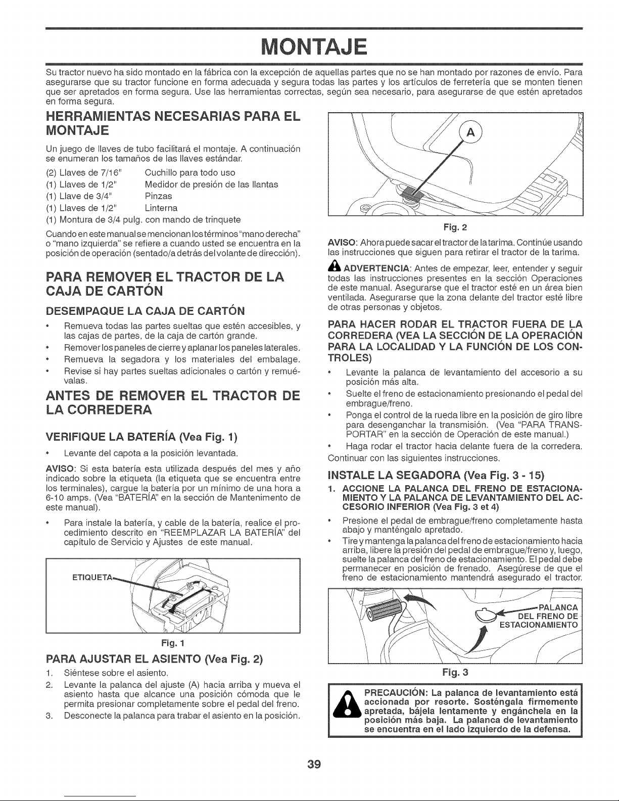
MONTAJE
Su tractor nuevo ha sido montado en la fabrica con la excepci6n de aqueJlas partes que no se han montado por razones de envio. Para
asegurarse que su tractor funcione en forma adecuada y segura todas las partes y los articulos de ferreteria que se monten tienen
que ser apretados en forma segura. Use las herramientas correctas, segOn sea necesario, para asegurarse de que esten apretados
en forma segura.
HERRAMIENTAS NECESARIAS PARA EL
\
Un juego de JJavesde tubo facilitarA eJmontaje. A continuaci6n
se enumeran los tamahos de JasIlaves estandar.
(2) Llaves de 7/16" CuchiJJo para todo uso
(1) Llaves de 1/2" Medidor de presi6n de las Ilantas
(1) LJave de 3/4" Pinzas
(1) Llaves de 1/2" Linterna
(1) Montura de 3/4 pulg. con mando de trinquete
Cuando eneste manual semencionan losterminos"mano derecha"
o "mano izquierda" se refiere a cuando usted se encuentra en la
posici6n de operaci6n (sentado/a detras del votante de direcci6n).
PARA REMOVER EL TRACTOR DE LA
CAJA DE CARTON
DESEMPAQUE LA CAJA DE CARTON
* Remueva todas las partes sueltas que esten accesibles, y
las cajas de partes, de la caja de cart6n grande.
Remover los paneJesde cierre y aplanar los paneJes laterales.
Remueva Ja segadora y los matedales del embalage.
Revise si hay partes sueltas adicionales o cart6n y remu@-
valas.
ANTES DE REMOVER EL TRACTOR DE
LA CORREDERA
VERmFmQUE LA BATERiA (Vea Fig. 1)
Levante del capota a la posici6n levantada.
AVJSO: Si esta bateria esta utilizada despu@s deJ mes y aho
indicado sobre la etiqueta (la etiqueta que se encuentra entre
los terminales), cargue la bateria por un minimo de una hora a
6-10 amps. (Vea "BATERI,_' en la secci6n de Mantenimento de
este manual).
Para instale la bateria, y cable de la bateria, realice el pro°
cedimiento descrito en "REEMPLAZAR LA BATER[_' det
capitulo de Servicio y Ajustes de este manual.
AWSO: Ahora puede sacar e{tractor de Jatarima. ContinOe usando
las instrucciones que siguen para retirar eJtractor de la tarima.
,_ ADVERTENCJA: Antes de empezar, leer, entender y seguir
todas las instrucciones presentes en la secci6n Operaciones
de este manual. Asegurarse que eJ tractor este en un Area bien
ventilada. Asegurarse que la zona delante del tractor este libre
de otras personas y objetos.
PARA HACER RODAR EL TRACTOR FUERA DE LA
CORREDERA (VEA LA SECCLAN DE LA OPERACJON
PARA LA LOCAUDAD Y LA FUNCLAN DE LOS CON-
TROLES)
Levante la palanca de levantamiento del accesorio a su
posici6n mas alta.
Suelte eJfreno de estacionamiento presionando eJpedal del
embrague/freno.
Ponga eJcontrol de Ja rueda libre en la posici6n de giro libre
para desenganchar la transmisi6n. (Vea "PARA TRANS-
PORTAR" en la secci6n de Operaci6n de este manual.)
Haga rodar eJ tractor hacia deJante fuera de la corredera.
Continuar con las siguientes instrucciones.
JNSTALE LA SEGADORA (Yea Fig. 3 - 15)
1. AOCtONE LA PALANCA DEL FRENO DE ESTAOJONA-
MJENTO Y LA PALANOA DE LEVANTAMIENTO DEL AO-
CESORJO iNFERiOR (Vea Fig. 3 et 4)
* Presione e{ pedal de embrague/freno completamente hasta
abajo y mantengalo apretado.
* Tire y mantenga Japalanca del freno de estacionamiento hacia
arriba, libere lapresi6n de{ pedal de embrague/freno y, luego,
sueJte JapaJanca deJfreno de estacionamiento. El pedal debe
permanecer en posici6n de frenado. Aseg_rese de que el
freno de estacionamiento mantendra asegurado el tractor.
F_g. 2
F_g. 1
PARA AJUSTAR EL ASJENTO (Vea Fig. 2)
1. Sientese sobre eJasiento.
2. Levante Ja palanca deJ ajuste (A) hacia arriba y mueva e{
asiento hasta que alcance una posici6n c6moda que Je
permita presionar completamente sobre e{ pedal del freno.
3. Desconecte lapalanca para trabar eJasiento en la posici6n.
DEL FRENO DE
ESTACIOV_°_"ANAMIENTO I
Fig. 3
_ PRECAUOtAN: La palanca de _evantamiento est_
accionada pot resorte. SostSngala firmemente_
bapretada, b_jeJa Jentamente y eng_nchela en _a
" posici6n m_s baja. La paJanca de levantamiento
se encuentra en eJ _ado izquierdo de _adefensa.
39
Page 40
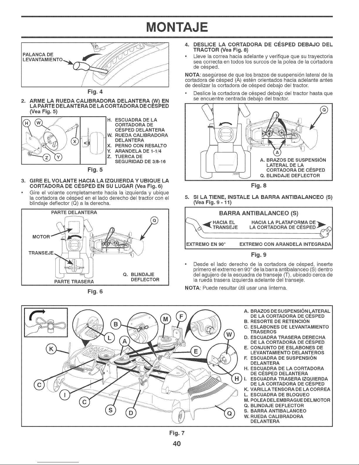
MONTAJE
PALANCA DE
Fig. 4
2,
ARME LA RUEDA CAMBRADORA DELANTERA (W) EN
LA PARTE DELANTERA DE LA CORTADORA DE CESPED
(Yea Fig. 5)
Ho ESCUADRA DE LA
CORTADORA DE
CESPED DELANTERA
W. RUEDA CAUBRADORA
DELANTERA
X. PERNO CON RESALTO
Y. ARANDELA DE 1-1/4
Z. TUERCA DE
SEGURJDADDE 3/8-16
F_g. 5
3, GIRE ELVOLANTE HACIA LA IZQUIERDAY UBIQUE LA
CORTADORA DE CESPED EN SU LUGAR (Vea Fig. 6)
* Gire el vo{ante completamente hacia la izquierda y ubique
la cortadora de cesped en e{ lado derecho del tractor con e{
blindaje deflector (Q) a la derecha.
PARTE DELANTERA
MOTOR
4, DESLICE LA OORTADORA DE CESPED DEBAJO DEL
TRACTOR (Yea Fig. 8)
* Lleve la correa hacia adelante y vedfique que su trayectoda
sea correcta en todos los surcos de la potea de la cortadora
de cesped.
NOTA: asegOrese de que los brazos de suspensi6n Jateral de la
cortadora de cesped (A) esten odentados hacia adelante antes
de deslizar la cortadora de cesped debajo del tractor.
Deslice la cortadora de cesped debajo del tractor hasta que
se encuentre centrada debajo del tractor.
Fig. 8
5. Sl LA TtENE, INSTALE LA BARRA ANTIBALANCEO (S)
(Vea Fig. 9 - 11)
i BARRA ANT_BALANCEO (S)
_( HAOJA EL
TRANSEJE
EXTREMO EN 90° EXTREMO CON ARANDELA INTEGRADA
PARTETRASERA
Fig. 6
Q° BUNDAJE
DEFLECTOR
Fig. 9
Desde e{ lado derecho de la cortadora de cesped, inserte
primero e{extremo en 90° de ta barra antibalanceo (S) dentro
del agujero de la escuadra de transeje (T), ubicado cerca de
la rueda trasera izquierda adelante del transeje.
NOTA: Puede resultar Otil usar una linterna.
A° BRAZOS DE SUSPENSION LATERAL
DE LA CORTADORA DE CESPED
B° RESORTE DE RETENCI6N
C° ESLABONES DE LEVANTAMIENTO
TRASEROS
D. ESCUADRA TRASERA DERECRA
DE LA CORTADORA DE CESPED
E° CONJUNTO DE ESLABONES DE
LEVANTAMIENTO DELANTEROS
E ESCUADRA DE SUSPENSION
DELANTERA
H° ESCUADRA DE LA CORTADORA
DE CESPED DELANTERA
I° ESCUADRA TRASERA IZQUIERDA
DE LA CORTADORA DE CESPED
K° VARILLATENSORA DE LA CORREA
L. ESCUADRA DE BLOQUEO
M. POLEADELEMBRAGUE DELMOTOR
Q. BUNDAJE DEFLECTOR
S. BARRA ANT_BALANCEO
WoRUEDA CAUBRADORA
DELANTERA
F_g. 7
4O
Page 41

MONTAJE
UBICACI6N _' 7,
DE LA BARRA
ANTJBALANCEO (S) ......................... *
Fig. 10
NOTA: Dependiendo del modeto, la escuadra (T) puede ser
diferente de la que se ilustra, pero el agujero para la barra anti°
balanceo estarA en la misma posici6n/ubicaci6n.
• Haga oscilar el extremo con la arandela integrada de la barra
antibalanceo (S) hacia la escuadra de la p{ataforma de la
cortadora de cesped en el lado derecho de la cortadora.
Inserte el extremo con la arandela integrada de la barra en
el agujero de la escuadra trasera de la cortadora de cesped
(D). Mueva la cortadora de cesped segOn sea necesado para
insertar el extremo con la arandeta integrada de la barra en
la escuadra trasera de la cortadora de cesped (D).
• Asegure con una arandela pequeha y un resorte de retenci6n
pequeho, como se ilustra.
INSTALE LOS ESLABONES DE LEVANTAMIENTO TRA-
SEROS (O) (Vea Fig, 13)
Inserte el extremo de vadlla del eslab6n de levantamiento
trasero (C) dentro del agujero (U) en el brazo de suspensi6n
del eje de levantamiento dettractor y haga oscilar el eslab6n
hacia abajo hacia la cortadora de c@sped.
Levante la esquina trasera de lacortadora de c@spedy ubique
la ranura en el conjunto de eslabones sobre la chaveta en
la escuadra trasera de la cortadora (D); asegure con una
arandela grande y un resorte de retenci6n grande.
Repita en eJ lado opuesto del tractor.
c. ESLABO.ESDE
\ '_,_ \ \ ,,, k.C.J LEVANTAMIENTO
",\ TRASEROS
., D° ESOUADRA
\.. "\ ", \\_r"_"_',\ TRASERA
....,", ", "_ _. DERECHA DE LA
'","........ CORTADORA DE
, //
Fig. 13
8. INSTALE EL ESLABON DELANTERO (E) (Yea Fig. 14)
* Gire el volante hasta ubicar las ruedas derechas en posici6n
de avarice.
* Desde la parte delantera de{ tractor, inserte e{ extremo de
varilla del estab6n detantero (E)a traves de{ agujero delantero
de la escuadra de suspensi6n de{antera del tractor (F).
* Muevase hasta e{ lado izquierdo de la cortadora e inserte
un resorte de retenci6n grande (G) a traves del agujero de{
eslab6n delantero (E) detr&s de la escuadra de suspensi6n
delantera (F).
* Inserte e{ otro extremo del estab6n (E) en e{ agujero de la
escuadra derecha de la cortadora de cesped (H) y asegure
con una arandela y un resorte de retenci6n pequeho (J).
NOTA: Requiere levantar la ptataforma.
u.AGuJERO
Fig. 11
6, INSTALE LOS BRAZOS DE SUSPENSK)N LATERAL DE
LA CORTADORA DE CESPED (A) EN EL CHASlS
(Yea Fig, 12)
* Ubique e{ agujero delantero de{ brazo de suspensi6n lateral
(A) sobre la chaveta en la parte exterior de{ chasis del tractor
y asegure con una arandela grande y un resorte de retenci6n
grande (B).
* Repita en e{ lado opuesto del tractor.
A. BRAZOS DE SUS-
PENSIONLATERAL
DELACORTADORA
DE CESPED
RETENOION
ERA DERECHA DE
LAOORTADORADE
CESPED
Fig. 12
UBtOAOION
DEL ESLABON ..............
DELANTERO .......... . / .............................,
E. CONJUNTO DE ESLABONES DE LEVANTAMmENTO DELANTEROS
Fo ESCUADRA DE SUSPENS_6N DELANTERA
G° RESORTE DE RETENOION GRANDE
H° ESOUADRA DE LA CORTADORA DE CESPED DELANTERA
J° RESORTE DE RETENCI6N PEQUENO
M° POLEA DEL EMBRAGUE DEL MOTOR
\
F_g. 14
41
Page 42
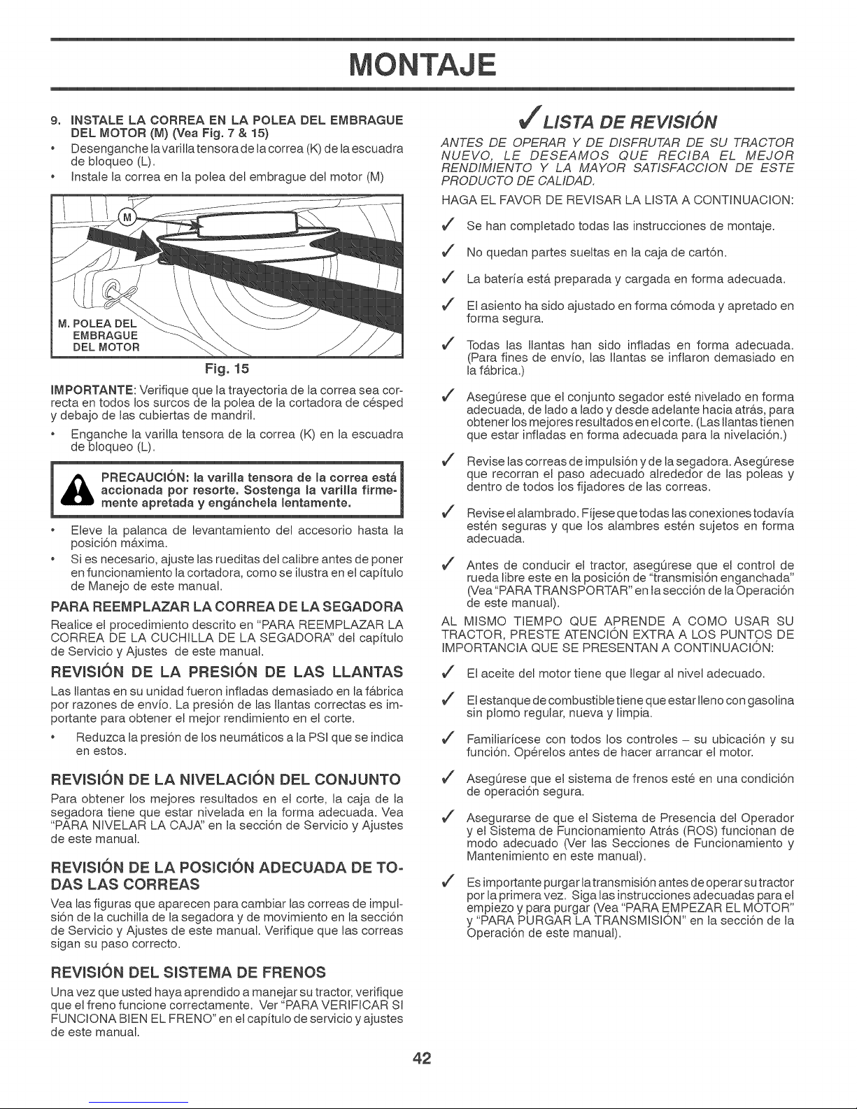
MONTAJE
9° INSTALE LA CORREA EN LA POLEA DEL EMBRAGUE
DEL MOTOR (M) (Vea Fig. 7 & 15)
* Desenganche lavarilla tensora de la correa (K)de la escuadra
de bloqueo (L).
Instale la correa en la potea del embrague del motor (M)
M. POLEA DEL
EMBRAGUE
DEL MOTOR
Fig. 15
IMPORTANTE: Verifique que latrayectoria de la correa sea cor=
recta en todos los surcos de la potea de la cortadora de cesped
y debajo de las cubiertas de mandril.
• Enganche la varilla tensora de la correa (K) en la escuadra
de bloqueo (L).
i PRECAUCI6N: _avariHa tensora de la correa estS|
• Eleve la palanca de levantamiento del accesodo hasta la
• Si es necesado, ajuste las rueditas del calibre antes de poner
accionada pot resorte° Sostenga la varilla firme-_
mente apretada y eng_ncheta lentamente, j
posici6n maxima.
en funcionamiento la cortadora, como se ilustraen el capitulo
de Manejo de este manual.
PARA REEMPLAZAR LA CORREA DE LA SEGADORA
Realice el procedimiento descrito en "PARA REEMPLAZAR LA
CORREA DE LA CUCHILLA DE LA SEGADOR_' del capitulo
de Servicio y Ajustes de este manual.
REVISION DE LA PRESION DE LAS LLANTAS
Las Ilantas en su unidad fueron inftadas demasiado en la f&brica
por razones de envio. La presi6n de JasIlantas correctas es im-
portante para obtener el mejor rendimiento en el corte.
Reduzca lapresi6n de los neumaticos a la PSI que se indica
en estos.
J"MSTA DE REVISION
ANTES DE OPERAR Y DE DISFRUTAR DE SU TRACTOR
NUEVO, LE DESEAMOS QUE REC/BA EL MEJOR
RENDIMIENTO Y LA MAYOR SAT/SFACC/ON DE ESTE
PRODUCTO DE CAL/DAD.
HAGA EL FAVOR DE REVISAR LA LISTA A CONTINUACION:
Se hart completado todas las instrucciones de montaje.
No quedan partes sueltas en la caja de cart6n.
La bateria esta preparada y cargada en forma adecuada.
El asiento ha sido ajustado en forma c6moda y apretado en
forma segura.
Todas las JJantas han side infladas en forma adecuada.
(Para fines de envio, las Ilantas se inflaron demasiado en
la fabrica.)
AsegOrese que et conjunto segador este nivelado en forma
adecuada, de lado a Jadoy desde adelante hacia atras, para
obtener los mejores resultados en et corte. (Las Ilantas tienen
que estar infladas en forma adecuada para la nivelaci6n.)
1
Revise las correas de impulsi6n y de la segadora. AsegOrese
que recorran el paso adecuado alrededor de las poleas y
dentro de todos los fijadores de las correas.
Revise el alambrado. Fijese que todas las conexiones todavia
est@n seguras y que los alambres esten sujetos en forma
adecuada.
Antes de conducir el tractor, asegOrese que eJcontrol de
rueda libre este en la posici6n de "transmisi6n enganchada"
(Vea"PARATRANSPORTAR" en Jasecci6n de laOperaci6n
de este manual).
AL MISMO TIEMPO QUE APRENDE A COMO USAR SU
TRACTOR, PRESTE ATENCI©N EXTRA A LOS PUNTOS DE
IMPORTANCIA QUE SE PRESENTAN A CONTINUACION:
El aceite del motor tiene que Ilegar al nivel adecuado.
El estanque de combustible tiene que estar Ilenocon gasotina
sin plomo regular, nueva y limpia.
Familiaricese con todos los controJes - su ubicaci6n y su
funci6n. Operelos antes de hacer arrancar el motor.
REVISION DE LA NIVELACJON DEL CONJUNTO
Para obtener los mejores resuttados en et corte, Ja caja de la
segadora tiene que estar nivetada en la forma adecuada. Vea
"PARA NIVELAR LA CAJ_' en la secci6n de Servicio y Ajustes
de este manual.
REWSJON DE LA POSlCION ADECUADA DE TO-
DAS LAS CORREAS
Yea las figuras que aparecen para cambiar Jascorreas de impuF
si6n de Jacuchilla de la segadora y de movimiento en la secci6n
de Servicio y Ajustes de este manual. Verifique que las correas
sigan su paso correcto.
REVISION DEL SlSTEMA DE FRENOS
Una vez que usted haya aprendido a manejar su tractor, verifique
que el freno funcione correctamente. Vet "PARA VERIFiCAR SI
FUNCIONA BEN EL FRENO" en elcapitulo de servicio y ajustes
de este manual.
AsegOrese que el sistema de frenos este en una condici6n
de operaci6n segura.
Asegurarse de que et Sistema de Presencia det Operador
y el Sistema de Funcionamiento Atr&s (ROS) funcionan de
mode adecuado (Ver las Secciones de Funcionamiento y
Mantenimiento en este manual).
Es importante purgar latransmisidn antes de operar sutractor
per la primera vez. Siga las instrucciones adecuadas para el
empiezo y para purgar (Vea "PARA EMPEZAR EL MOTOR"
y "PARA PURGAR LA TRANSMISION" en la secci6n de la
Operaci6n de este manual).
42
Page 43

f
OPERACION
Estos sfmbotos pueden aparecer sobre su tractor o en la literatura proporcionada con e{producto. Aprenda y comprenda sus significados.
MARCHA ATRAS NEUTRO ALTO BAJO R,_PIDO LENTO
ESTRANGU-
LACI©N
O
MOTOR
APAGADO
ENSENDIDAS
ACCESORIO DEL
EMBRAGUE
ENGANCHADO
(Solamente para los
modelos automatico)
FUNCIONAMIENTO CERRADO
LUCES
RUEDA LIBRE
SISTEMA ENCENDIDO EN MARCHA ESTACIONAMIENTO ESTACIONAMIENTO
COMBUSTIBLE BATERIA
ACCESORIO DEL
EMBRAGUE
DESENGANCHADO
MOTOR MOTOR FRENO DE FRENO DE ABERTA
÷
MARCHA MARCHA ALTURA DE LA
ATRAS HACIA ADELANTE SEGADORA
PEDAL DE FRENO/
DE EMBRAGUE
PELIGRO indica un peligro que, si no se evita,
provoca muerte o lesiones graves.
ADVERTENCIA indica un peligro que, si no se evita,
puede provocar muerte o lesiones graves.
PRECAUC_0N indica un peligro que, si no se evita,
puede provocar lesiones ligeras o moderadas.
MANTENGA EL PELIGROS DE
AREA DESPEJADA PENDIENTES
(Vea la secci6n de las reglas de seguridad)
IGNICION
LEVANTAMIENTO
DE LA SEGADORA
PELIGRO, GUARDE LAS
MANOS Y LOS PIES LEJOS
No seguir las siguientes instrucciones
puede provocar heridas o muerte. Los
simbolos de aviso de seguridadse utilizan
para identificar informaciones de seguridad
relativas a peligros que puedenprovocar la
muerte, heridas graves yio daSos a la
maquina.
PRECAUCION cuando se utiliza sin el simbolo de aviso,
indica una situacion que puede provocar daSos al
tractor y/o al motor.
SUPERFICIES CALIENTES indica un peligro que,
si no se evita, puede provocar la muerte, lesiones
graves y/o danos a la maquina.
FUEGO indica un peligro que, si no se evita, puede
provocar la muerte, lesiones graves y/o danos
a la maquina.
43
Page 44

y
OPERACJON
FAMIUARICESE CON SU TRACTOR
LEA ESTE MANUAL DEL OPERARIO Y LAS REGLAS DE SEGURIDAD ANTES DE OPERAR SU TRACTOR
Compare las iJustraciones con su tractor para famiJiarizarse con Jas ubicaciones de Jos diversos controtes y ajustes. Guarde este
manual para referencia en eJfuturo.
Nuestros tractores cumplen con Jos est&ndares de seguridad del American National Standard institute.
(A) PALANCA DEL LEVANTAMiENTO DEL ACCESORIO- Se
usa para levantar, bajar y ajustar el conjunto segador o los dem&s
accesorios montados en su tractor.
(B) PEDAL DEL EMBRAGUEiFRENO -Se usa para de-
sembragar y frenar el tractor y para hacer arrancar el motor.
(C) PALANCA DEL FRENO DE ESTACJONAMIENTO -Ase-
gura e{ pedaJ de{ embrague/freno en la posici6n del freno.
(D) CONTROL DE ACELERACJON - Se usa para controtar Ja
velocidad del motor.
(E) JNTERRUPTOR DEL EMBRAGUE DEL ACCESORJO - Se
usa para enganchar las cuchillas segadoras, o Josdem&s acce-
sorios montados en su tractor.
(F) INTERRUPTOR DE IGNJCJ6N - Se usa para hacer arrancar
o hacer parar el motor.
F_g. 16
(G) SlSTEMA DE FUNCJONAMJENTO HACJA ATRAS (ROS)
EN POSJCJON "ON"-Permite Ja operaci6n de{ conjunto
segador o otro accesorio accionado mientras que en reves.
(H) JNTERRUPTOR DE LA LUZ - Enciende y apaga JasJuces
delanteras.
(J) PALANCA DE CONTROL DE MOVIMIENTO - Selecciona Ja
velocidad y Jadirecci6n del tractor.
(M) CONTROL DE RUEDA UBRE -Desengancha la trans-
misi6n para empujar o arrastrar.
(N) CONTROL DE ESTRANGULACJON -Se usa cuando se
hace arrancar un motor frio.
(P) DISPOSBVO DE AWSO DE SERVJCIO / CRONOMETRO
-Indica cu&ndo hay que hacerles el servicio al motor y a la
cortadora.
(Q) PUERTO DE LA ENGERGJA 12 VOLT - Se usa para los
accesorios 12=vott.
44
Page 45

f
OPERAC+ON
COMO USAR SU TRACTOR
PARAAJUSTAR EL FRENO DE ESTACIONAMIEN+
TO (Vea Fig+ 17)
Su tractor viene equipado con un interruptor sensor que
exige la presencia det operador. Cuando el motor est& fun-
cionando, si el operador trata de bajarse del asiento sin prim+
ero apticar el freno de estacionamiento, se apagara el motor.
+ Presione el pedal (C) del freno/embrague completamente y
sostengalo.
+ Jale hacia arriba la palanca del freno de mano (O) y man-
tengala en esa posici6n; suelte graduaJmente el pedaJ del
embrague/freno (B), y luego suette la palanca del freno de
mano+ El pedal tiene que quedar en la posici6n de freno.
AsegOrese que el freno de estacionamiento va a sujetar el
tractor en forma segura.
Fig. 17
PARADA (Vea Fig, 18)
CUCHJLLAS DE LA SEGADORA -
+ Mueva el control del embrague del accesorio a la posici6n
"DESENGANOHADO" (t_).
MOTOR -
+ Mover la palanca de mando entre la posici6n (D) de velocidad
media y m&xima (r&pida).
NOT.&: Si no se mueve el control de la aceteraci6n a la
posici6n de lento y se permite que et motor ande en vacio
antes de pararlo puede producir la contraexplosi6n del motor.
+ Gire la Ilave de ignici6n (F) a la posici6n de apagado "STOP"
y remueva la Ilave al abandonar el tractor para evitar el uso
no autorizado.
+ Nunca use la estrangulaci6n para parar el motor.
IMPORTANTE: DEJANDO EL HNTERRUPTORDE LA HGNHCH6NEN
CUALQUHERPOSHCHONOTRAQUE"STOP"CAUSARHQUE LABATERIA
SE DESCARGUE (MUERTA).
NOT,A: Bajo ciertas condiciones, cuando el tractor est& parado
con el motor andando en vacio, los gases de escape del mo-
tor caliente pueden hacer que el cesped se ponga "cafe." Para
etiminar esta posibilidad, siempre pare el motor cuando pare el
tractor en &reas con cesped.
PREOAUCI6N: Siempre pare el tractor
completamente, eegQn ee ha deecrito ante-
riormente, antes de abandonar la poeici6n
det operador.
PARA USAR EL CONTROL DE LA ACELERACK_N
(D) (Vea Fig. 19)
Siempre opere el motor a una aceleraci6n compteta.
+ Si el motor funciona a una velocidad inferior a la maxima
(rapida), su rendimiento disminuye.
+ El rendimiento 6ptimo se obtiene a la velocidad maxima
(rapida).
(|) ATTACHMENT
CLUTCH SWITCH
"DISENGAGED"
Fig. 18
IMPULSION DE RECORRIDO -
Para parar et mecanismo imputsor, presione el pedal del
freno/embrague completamente.
Mueva la palanca de control de movimiento (J) a la posici6n
de neutro.
(_} ATTACHMENT
CLUTCH SWITCH
"ENGAGED"
PARA USAR EL CONTROL DE ESTRANGULACION
(N) (Yea Fig. 19)
Use el control de estrangulaci6n cuando este haciendo arrancar
un motor frio. No Io use para hacer arrancar un motor caliente.
+ Para enganchar elcontrol de estrangutaci6n (N),tire la manilJa
hacia afuera. Lentamente, empuje la manilla hacia adentro
para desengancharlo.
45
Page 46

OPERACION
y
PARA MOVERSE HACIA ADELANTE Y HACIA
ATRAS (Vea Fig. 20)
La direccidn y la ve{ocidad de{ movimiento son controtadas por
medio de la palanca de control de movimiento (J).
Fig. 2O
Haga arrancar el motor con la palanca de controt de movi°
miento en la posici6n de neutro.
Suelte el freno de estacionamiento.
Lentamente, mueva la palanca de control de movimiento a
la posici6n deseada.
PARA AJUSTAR LA ALTURA DE CORTE DE LA
SEGADORA (Vea Fig. 8)
La posici6n de la palanca elevadora (A) determina a que altura
se cortar& el cesped.
PARA AJUSTAR LAS RUEDAS CAUBRADORAS
(Vea Fig. 22)
Las ruedas caJibradoras est&n bien ajustadas cuando se eno
cuentran un poco a distancia del terreno al mismo tiempo que la
segadora este a la altura de corte deseada. Entonces las ruedas
calibradoras mantienen el conjunto segador en posici6n para
prevenir el corte raspeo en casi todos los terrenos.
AWSO: Ajuste las ruedas calibradoras con el tractor en una
superficie nivelada ptana.
1. Ajuste la segadora a laaltura de corte deseada con Jamanilla
de ajuste de altura (Vea "PARA AJUSTAR LA ALTURA DE
CORTE DE LA SEGADOR,_' en la secci6n de Operaci6n de
este manual).
2. Con tasegadora a Jaaltura deseada para la posici6n de corte,
se tienen que montar las ruedas calibradoras de modo que
queden un poco sobre el suelo. InstaJe Jas ruedas calibra-
doras en el agujero adecuado como indicados. Apdete con
seguridad.
3. Repita el procedimiento para el lado opuesto instalando la
rueda calibradora en el mismo agujero de ajuste.
3/4"
Fig. 21
Coloque la palanca etevadora en la ranura de la altura de-
seada.
La gama de la altura de corte es de aproximadamente 25,4 a
101,6 mm (1 a 4 pulgadas). Las alturas se miden desde et suelo
a la punta de la cuchilla cuando el motor no est& funcionando.
Estas alturas son aproximadas y pueden variar dependiendo de
las condiciones det sueto, de la altura det cesped y del tipo del
cesped que se est& segando.
Elcesped promedio debe cortarse aproximadamente a 63,5 mm
(2-1/2 pulgadas) durante la temporada fria y sobre 76,2 mm
(3 pulgadas) durante los meses calurosos. Para obtener un
cesped m&s saludable y de mejor apariencia, siegue a menudo
y despues de un crecimiento moderado.
Para obtener et mejor rendimiento de corte, el cesped que
tiene m&s de 152,4 mm (6 putgadas) de altura debe segarse
dos veces. Haga el primer corte retativamente alto; etsegundo
a la altura deseada.
Fig. 22
PARA OPERAR LA SEGADORA
Su tractor viene equipada con un interruptor sensor que exige
la presencia del operador. Si el motor est& funcionando y el emo
brague del accesorio est& enganchado y el operador trata de
bajarse del asiento, se apagar& el motor. Tiene que mantenerse
sentado compteta y centralmente en el asiento para impedir que
el motor vacile o se apague cuando se opere su equipo en terreno
disparejo, &spero o en cerros.
Elija a qu@altura cortar& el cesped (Vea" PARA AJUS-TAR
LA ALTURA DE CORTE DE LA SEGADORA".)
Haga arrancar las cuchiJlas de la segadora enganchando el
control del embrague del accesorio.
PARA PARAR LAS CUCHILLAS DE LA SEGADORA
Desenganche el control del embrague del accesorio.
& PRECAUOION: No opere la segadora sin, ya sea,
el recogedor de c_sped completo en las sega-
doras as_ equipadas o con la protecci6n contra
la descarga en su _ugar (Vea Fig. 23).
Fig. 23
46
Page 47

OPERACION
f
FUNCIONAMiENTO ATR_.S (Vea Fig. 24)
l_dtractor est& equipado con el Sistema de Funcionamiento Atr&s
(ROS). Cualquier tentativa del operador de viajar marcha atr&s
con el embrague puesto apagar& el motor a menDs que la Ilave
de ignici6n se ponga en la posici6n de "ON" del ROS.
_IbATENDK)N: Ir marcha atr&s con el embrague puesto para
cortar, no es recomendable. Poniendo el ROSen posici6n "ON",
para permitir elfuncionamiento atr&s con el embrague puesto, se
tiene que hacer s6to cuando el operador Io considera necesario
para reposicionar la m&quina con el dispositivo embragado. No
siegue en reves a menDs que sea absotutamente necesario.
USAR EL SISTEMA DE FUNCIONAMIENTO ATRAS (ROS) -
Utilice et tractor solamente si est& seguro de que no ingresar&n
hinDS ni otras personas o animales al &rea donde se va a cortar
el cesped.
Mover la palanca de mando del movimiento en la posici6n
neutro.
Con el motor en marcha, girar la Ilave de{ interruptor de la
ignici6n en el sentido inverso al de las agujas del reloj hasta
la posici6n "ON".
Mire hacia abajo y hacia atras no s61o antes de ir marcha
atr&s, sino mientras este yendo marcha atr&s.
Mover despacio la palanca de mando del movimiento
hacia la posici6n atras para empezar el movimiento.
Cuando el uso del ROS es m&s necesario, de vuelta a la
Ilave de ignici6n en el sentido de las agujas del reIoj hasta
la posici6n "ON".
Paravolver a empezar con el movimiento, suelte lentamente,
el freno de estacionamiento y el pedal de{ embrague/freno.
Lentamente, mueva la palanca de control de movimiento al
ajuste mas lento.
Gire siempre lentamente.
PARA TRANSPORTAR (Yea Fig. 25)
Cuando empuje oarrastre su tractor aseg0rese de desenganchar
la transmisi6n poniendo el control de la rueda libre en la posici6n
de marcha de rueda fibre. El control de marcha de rueda fibre
esta situado en la barra de tracci6n trasera del tractor.
Levante la palanca de levantamiento del accesorio a su
posici6n mas alta.
Tire del mando de la rueda libre hacia afuera y hacia abajo
hasta que se coloque en la guia y su6ltalo de manera que
se mantenga en la posici6n de desenganchada.
No empuje o arrastre e{ tractor a mas de 3,2 km/h (2 mph).
Para votver a accionar la transmisi6n, invierta este procedi-
miento.
TRANSMiSSiON ENGAGED
MOTOR EN POSJCK)N "ON"
(OPERAOt6N NORMAL)
Fig. 24
PARA OPERAR EN CERROS
o hacia abajo en cerros con pendientes
ADVERTENDIA: No mane]e hacia arriba
superiores a 15° y no maneje atravesando
ninguna pendiente. UtiHce _agu_a de la pen-
diente proporcionada en la parte posteriora
de este manual
Escoja la vetocidad m&s lenta antes dearrancar hacia arriba
o hacia abajo en cerros.
Evite parar o cambiar la velocidad en cerros.
Si es absolutamente necesario el parar, empuje el pedal
det embrague/freno rapidamente a la posici6n de freno y
enganche el freno de estacionamiento.
Mueva la palanca de control de movimiento a la posici6n de
neutro.
IMPORTANTE: LA PALANCA DE CONTROL DE MOVlMIENTO
NOVUELVE A LA POSICION DE NEUTRO CUANDO EL PEDAL
DEL EMBRAGUE/FRENO ESTA PRESIONADO.
TRANSMiSSiON DISENGAGED
F_g. 25
AVISO: Para proteger el capota contra e{ daSo cuando transporte
su tractor en un cami6n o remolcador, aseg0rese que el capota
este cerrado y asegurado al tractor. Use los medics apropiados
para amarrar e{ capota al tractor (cuerdas, cordeles, etc.).
REMOLQUE DE CARRETILLAS O OTROS AC-
CESORIOS
Remotque solamente los accesorios recomendados y especifica-
dos por el fabricante del tractor. Use sentido com0n cuado este
remoicando. Las cargas pesadas, cuando este yendo sobre una
pendiente, son pefigrosas, las flantas pueden perder su tracci6n
con el terreno y pueden ocasionar que pierda el control de su
tractor.
MECANHSMO DE AV_SO DE SERViCeD / CRONO-
METRO
El recordatorio de servicio muestra el n0mero total de horas de
funcionamiento det motor e indica e{ momento en que e{ motor o
la cortadora de cesped necesita mantenimiento. Despues de cada
50 horas defuncionamiento, el icono de lata de aceite permanece
encendido durante 2 horas o hasta que se realiza el restabteci-
miento manual. Para restablecer la pantalla manualmente, gire
el interruptor de arranque a la posici6n de encendido y despues
a la de apagado cinco veces (1 segundo encendido, 1 segundo
apagado). Para el mantenimiento del motor y de la cortadora
de cesped, consulte la secci6n Mantenimiento de este manual.
NOTA: El recordatorio de servicio se activa cuando la Itave de
contacto esta en cualquier posici6n que no sea "STOP". Para
una lectura precisa, la flave debe permanecer en la posici6n
"STOP" cuando el motor no esta en marcha.
47
Page 48

OPERACION
y
ANTES DE HACER ARRANCAR EL MOTOR
REVISE EL NIVEL DE ACE_TE DEL MOTOR
El motor de su tractor se envia de fAbnca ya Ileno con aceite de
peso para verano.
Revise el aceite del motor con el tractor en terreno nivelado.
Levante y quite la varilla indicadora de nivel de relleno del
aceite; limpie el aceite. Reinserte la varilla en el tube y
empOjela hacia abajo firmemente en su lugar. Remueva y
lea el nivel del aceite. Si es necesario, agregue aceke hasta
se Ilegue a la marca de Ileno (FULL) en la varilla indicadora
de nivel. No Io Ilene demasiado.
Para la operaci6n en clima frio, debe cambiar et aceite para
poder arrancar mAs fAcilmente. (Vea "Tabta de Viscosidad
Del Aceite" en la secci6n de Mantenimento de este manual.)
Para cambiar el aceite del motor, vea la secci6n de Manten-
imiento en este manual.
AGREGUE GASOMNA
Llene el tanque de combustible hasta la parte inferior del
cuello de relleno. No Io Ilene de m&s. Use gasotina normal
nueva y limpia con un minimo de 87 octanos. No mezcle
aceite con gasolina. Compre combustible en cantidades
que se puedan usar en 30 dias para asegurar la frescura
del combustible.
&
IMPORTANTE: CUANDO SE OPERE EN TEMPERATURAS
POR DEBAJO DE 32°F (0°C) USE GASOLINA DE INVERNO
LIMPIA Y NUEVA PARA AUEDAR A ASEGURAR UN BUEN
ARRANQUE EN CLIMA FRiO.
PRECAUCl6N: Los combustibles mezclados con al-
cohoJ (Hamados gasohol o que usan etanol o metano 0
pueden atraer la humedad, Roque provoca maseparaci6n
y formaci6n de _cidos durante e_almacenamiento° Em
gas 8cido puede daSar el sistema de combustible de
un motor mientras ee encuentra en almacenamiento.
Para evitar probmemas con e_ motor, el sistema de
combustible se debe vaciar antes de_ almacenamiento
durante 30 d_as o mSso Drene el tanque de gasoHna,
arranque e_ motor y h_gaio funcionar hasta que lae
tuberias de combustible y del carburador est_n vac_as
Use combustible nuevo en _a temporada eiguiente.
Coneulte lae Instrucciones de AImacenamiento para
obtener informaci6n adicionat. Nunca use productos
Hmpiadores para motor o carburador en el tanque de
combustible porque puede provocar daSos irreparableso
El estabHizador de combustible es una alternativa acept-
able para minimizar _aformaci6n de dep6sitoe de goma
de combustible durante e_ almacenamiento. Agregue
estabHizador a la gasoHna en el tanque de combustible
o recipiente de a_macenamientoo Siga siempre _apro-
porci6n de mezcla que se encuentra en el recipiente det
estabiHzador. Deje funcionar el motor al menos durante
10 minutos deepu_s de agregar el estabiHzador para
permitir que eJ eetabHizador Hegue a_ carburador. No
vacie e_ tanque de gasoHna y e_ carburador ei utiHza
estabHizador de combustible.
PARA HACER ARRANCAR EL MOTOR (Vea Fig. 16)
At hacer arrancar e{ motor por la primera vez o sise ha acabado
el combustible del motor, se necesitara tiempo para e{ arranque
extra para mover el combustible desde elestanque hasta el motor.
AsegOrese que e{ control de rueda libre este en la posici6n
enganchada.
Sientase enel sill6n en ta posici6n de operaci6n, suelte elpedal
del embrague/freno y ponga el freno de estacionamiento.
Ponga la palanca de control de movimiento en la posici6n
de neutro.
Mueva e{ embrague del accesono a la posici6n "DESEN-
GANCHADO".
Mueva el control de la aceleraci6n a la posici6n de r&pido.
Tire e{contro{ de estrangulaci6n a laposici6n de estrangulaci6n
para el arranque de un motor frio. Para el arrancar un motor
caliente e{ uso de{ control de la estrangulaci6n puede que
no sea necesario.
AWSO: Antes de arrancar, lea las instrucciones siguientes para
e{ arranque en clima frio y templado.
Inserte la Ilave en ta ignici6n y gire la Ilave en e{ sentido que
giran las manillas del reloj a la posici6n de arranque start, y
suette la Ilave tan pronto como arranque el motor. No haga
funcionar el arrancador continuamente por mas de quince
seg.undos pot minuto. Si el motor no arranca despues de
vanos intentados, mueva et control de la estrangutaci6n
hacia adentro, espere unos cuantos minutos y trate de
nuevo. Si e{ motor sigue sin funcionar, estire del control de
la estrangulaci6n y trate de nuevo.
ARRANQUE CON TIEMPO TEMPLADO (50°F/10°C y mas)
Cuando arranque e{ motor, empuje e{ control de la estrangu-
laci6n hasta que e{ motor empiece a funcionar m&s suave°
mente. Si e{ motor empieza a funcionar mal, estire del control
de la estrangutaci6n un poco por unos cuantos segundos y
entonces continue a empujar lentamente e{ control.
Los accesorios y el embrague de sueto ahora puede set
utilizados. Si e{motor no acepta esta carga, vuelva aarrancar
el motor para permitirle que se caliente por un minuto,
utilizando e{ estrangulador como describido arriba.
ARRANQUE OON TEMPO FR[O (50°F/10°O y menos)
Cuando arranque e{ motor, empuje lentamente e{ control
de la estrangulaci6n hacia adentro hasta que e{ motor
empiece a funcionar suavemente. Siga empujandoto poco
a poco permitiendo que el motor acepte pequeSos cambios
de vetocidad y carga, hasta que este comptetamente hacia
adentro. Si el motor empieza a funcionar mal, estire del control
de la estrangulaci6n un poco por unos cuantos segundos
y continQe a empujar el control hacia adentro. Esto puede
requerir que el motor se caliente por unos cuantos minutos,
depende de la temperatura.
CALENTAMENTO PARA LA TRANSMISION AUTOMATICA
Antes de conducir la unidad enun tiempo frio, latransmisi6n debe
set calentada como las instrucciones siguientes:
AsegOrese que e{tractor este situado en una superficie
nivelada.
Ponga la palanca de control en neutro. Alivie el freno de
estacionamiento y deje que e{ embrague/freno vuelva
a la posici6n de operaci6n.
Permita que latransmisi6n se caliente durante un minuto.
Esto puede ser echo durante e{tiempo de calentamiento
del motor.
Los accesorios pueden set utilizados durante el periodo del
recalentamiento del motor despues que la transmisi6n halla
side calentada y puede requedr que el control de la estran-
gulaci6n sea estirado un poco.
48
Page 49

f
OPERACION
PURGAR LA TRANSMISK_N CONSEJOS PARA SEGAR
NO use cadenas de Ilanta cuando la carcasa de la cortadora
de c@sped este colocada en el tractor.
ganche la palanca del controJ de rueda libre
PRECAUCK)N: Nunca enganche o desert°
cuando el motor esta funcionando°
Para asegurar la operaci6n y ejecuci6n adecuada, es recomen-
dado que Jatransmisi6n sea purgada antes de operar el tractor
para laprimeravez. Este proceso removera cualquier aire adentro
de la transmisi6n que se halla formado durante e{ transporte de
su tractor.
IMPORTANTE: SI POR ACASO SU TRANSMISI©N DEBE SER
REMOVlDA PARA SERVICIO O REEMPLAZO, DEBE SER
PURGADA DESPUES DE LA REINSTALACION Y ANTES DE
OPERAR EL TRACTOR.
1. Para mayor seguridad, ubique el tractor en una superficie
nivelada, despejada de cualquier objeto y abierta, con e{
motor apagado y e{ freno de mano puesto.
2. Desenganche Jatransmisi6n poniendo el control de rueda
libre en la posici6n de desenganchado. (Vea "PARA EL
TRANSPORTE" en esta secci6n de este manual.)
3. Sentado en e{asiento deltractor, empiece el motor. Despues
que este corriendo e{ motor, mueva e{ control de estrangula=
ci6n a la posici6n de lento. Con tapalanca de rueda libre en{a
posici6n de neutral, desenganche lentamente el embrague/
el freno del pedal.
La segadora debe estar nivelada en forma adecuada para
obtener e{ mejor rendimiento al segar. Vea"PARA NIVELAR
LA CAJA DE LA SEGADOR,_' en la secci6n de Servicio y
Ajustes de este manual.
El lado izquierdo de la segadora se debe usar para recorte.
Maneje de modo que los recortes se descarguen en e{ &rea
que ya ha sido cortada. Mantenga e{ &rea de corte a la
derecha del tractor. Esto producir& una distribuci6n m&s
pareja de los recortes y un corte m&s uniforme.
At segar las &rea grandes, empiece girando a la derecha
de modo que losrecortes se descarguen, alej&ndose de los
arbustos, cercos, entradas de autom6viles, etc. Despues de
una o dos vue{tas, siegue en la direcci6n opuesta, haciendo
virajes a la izquierda, hasta que termine (Vea Fig 26).
}J
_1 PRECAUCJ6N: En eJ transcurso del paso 4,
4. Mueva lapalanca det control de movimiento a la posici6n total
de adelante y suj@tela durante cinco (5) segundos. Mueva Ja
palanca hacia la posici6n total de marcha atr&s y sujete{a du-
rante cinco (5) segundos. Repita este proceso tres (3)veces.
5. Mueva Japalancade{control demovimiento alaposici6n de neu-
tro. Apague el motor y embrague elfreno de estacionamiento.
6. Enganche la transmisi6n poniendo et control de rueda libre
en Japosici6n de conducir. (Vea "PARA TRANSPORTAR"
en esta secci6n del manual.)
7. Sentado en e{asiento deltractor, empiece e{motor. Despues
que este corriendo e{ motor, mueva e{ control de estrangu-
laci6n media (1/2) velocidad. Con la palanca de control de
movimiento a Japosici6n de neutro, lentamente desenganche
e{ embrague/e{ freno del pedal.
8. Mueva lentamente la palanca de control de movimiento hacia
adelante, despues que e{tractor se mueva aproximadamente
cinco (5) pies (1,5 m), mueva lentamente con la palanca de
control demovimiento a laposici6n contraria. Despu@s que e{
tractor se mueva aproximadamente unos cinco (5) pies (1,5
m) vuelva a poner la patanca de control de movimiento en
la posici6n de neutro. Repita este procedimiento lapalanca
de control de movimiento tres (3) veces.
Su transmisi6n esta ahora purgado y dispuesto para la operaci6n
normal.
puede que de pronto se pongan en movimiento
Ins ruedas.
(
Fig. 26
Si e{cesped est& demasiado alto, se debe segar dos veces
para reducir la carga y los posibtes peligros de incendio
debido a los recortes secos. Haga el primer corte relativa-
mente alto; el segundo a la altura deseada.
No siegue elcesped cuando esta mojado. El cesped mojado
taponara la segadora y dejara montones indeseables. Per-
mita que se seque el cesped antes de segarlo.
Siempre opere el motor con una aceleraci6n completa cuando
siegue para asegurarse de conseguir un mejor rendimien-
to y una descarga apropiada de los matedales. Regute la
velocidad de recorrido seleccionando un cambio Iosuficien-
temente bajo para obtener un rendimiento de corte de parte
de su segadora y tambien Jacalidad del corte deseada.
Cuando opere con accesorios, seleccione una velocidad de
recorrido que se acomode al terreno y le permita obtener el
mejor rendimiento del accesorio que se esta usando.
49
Page 50

MANTENIMENTO
PROGRAMA DE MANTENIMIENTO CADA USO 8 HORAS
Revisar la operaci6n del freno _
Revisar la presi6n de las llantas _
Verificar la sistemas presencia del operador y sistemas "ROS"
m Revisar si hay sujetadores sueltos
H Afilar/cambiar las cuchillas de la segadora
Tabla de lubricacion
T Revisar el nivel de bateria
0 Limpiar la bateria y los tereminales
R Limpie los residuos de la placa de direccion,
Revisar el enfriamiento del transeje
Compruebe la nivelaci6n del cortacespedes
Inspeccione las correas trapezoidales
Revisar el nivel del aceite del motor _
Cambiar el aceite del motor (Modelos con filtro de aceite)
Cambiar el aceite del motor (Modelos sin filtro de aceite)
Limpiar el filtro de aire
T Limpiar la rejilla de aire
O Inspeccionar el silenciador/amortiguador de chispas
R Cambiar el filtro de aceite (si equipado)
Limpiar las aletas de enfriamiento
Cambiar la bujia
Cambiar el cartucho de papel del filtro de aire
Cambiar el filtro de combustible
1- Cambiar mAs a menudo cllando se opere bajo carga pesada o en ambientes con altas temperaturas
2- Dar servicio mAs a menudo cuando se opere en condiciones sucias o polvorosas
ANTES DE CADA
3- Cambiar las cuchillas mas a menudo cllando se siegue en suelo arenoso
4- No requerido s} equipado con una bateria libre de mantenimiento,
CADA CADA CADA CADA
25HORAS 50HORAS 100 HORAS TEMPORADA
ALMACENAMIENTO
v' v"
J
_1,2 v'
J
_1,2
5- Yea "LIMPIEZA" en la secci6n de
Mantenimento de este manual
RECOMENDACIONES GENERALES
La garantia de este tractor no cubre los articutos que han estado
sujetos al abuso o a la negligencia del operador. Para recibir todo
eJvalor de lagarantia, e{operador tiene que mantener lasegadora
segOn las instrucciones descdtas en este manual.
Hay algunos ajustes que se tienen que hacer en forma peri6dica
para poder mantener su tractor adecuadamente.
At menos una vez cada estaci6n comprobar si es necesado
efectuar los adjustes descdtos en las secciones de Servicio y
Ajustes de este manual.
Una vez al a_o, cambie la bujia, limpie o cambie el filtro de
aire y revise si las cuchitlas ylas correas est&n desgastadas.
Una bujia nueva y un filtro de aire limpio aseguran una mezcla
de aire-combustible adecuada y le ayudan a que su motor
funcione mejor y que dure m&s.
ANTES DE CADA USO
Revise el nivel del aceite det motor.
Revise la operaci6n de los frenos.
Revise la presi6n de las Ilantas.
Verifique que el sistema de presencia del operado y ROS
funcionen adecuatamente.
Revise si hay sujetadores sueltos.
TABLA DE LUBRICACION
_ ACCESORJO _ ACCESORIO
DE GRASA DE GRASA DEL
DELARBOL ARBOL
0}
DE GRASA DEL ACCESORJO
RODAMJENTO DE GRASA DEL
DE LA RUEDA RODAMJENTO
DELANTERA DE LA RUEDA
DELANTERA
0}
DEL
ENGRANAJE
DE SECTOR
DE
DJRECCt6N
02501
(_ Grasa de proposito general
Re%rase a la secci6n deI"MOTOR" en Mantenimiento
IMPORTANTE: NO ACEITE O ENGRASE LOS PUNTOS PIVOTES,
LOS QUE TIENEN RODAMIENTOS DE NILON ESPECIALES, LOS
LUBRICANTES VISCOSOS ATRAERA, N POLVO Y MUGRE, LO QUE
ACORTARA LA DURACION DE LOS RODAMIENTS, SI CREE QUE
LUBRICARSE, USE SOLAMENTE UN LUBRICANTE TIPO GRAFITO
DE POLVO SECO EN FORMA MODERADA,
MOTOR
ACCESORJO
DE GRASA
DELMANDRJL
50
Page 51

MANTENIMENTO
Siempre observe las reglas de segundad cuando de manteni°
miento.
OPERACL6N DEL FRENO
Si eltractor necesita mas de cinco (5)pies (1,5 m)para detenerse a
la maxima velocidad al cambio mas alto en una superficie nivelada,
de hormig6n o pavimentada, hay que hacede el servicio aJfreno.
Vea "CONTROLAR Y AJUSTAR EL FRENO" en el capitulo de
Servicio y ajustes de este manual.
LLANTAS
o Mantengatodos los neumaticos con lapresi6n deaJreadecuada.
(Vea la PSI que se indica en estos.)
o Mantenga las Ilantas sin gasofina, aceite osubstancias quimicas
para control de insectos que pueden dahar la goma.
o Evite los tocones, las piedras, lasgrietas profundas, los objetos
afilados y otros peligros que pueden dafiar a las flantas.
AVISO: Para arreglar las Ilantas perforadas y pera prevenir que
tenga Ilantas pinchadas a causa de pequehas fugas, puede
comprar el sello para tlantas de su comerciante de partes de
repuesto mas cercano. EIsello previene que las Jlantas se sequen
y tambien la corrosi6n.
SlSTEMA PRESENCIA OPERADOR Y SlSTEMA FUN°
CLONAMIENTO ATRAS (ROS) (Vea Fig. 27)
Asegurarse de que el sistema de presencia del operador, el
sistema de trabajo y et sistema funcionamiento atras funcionen
bien. Si tu tractor no funci6n como descrito, reparar el problema
inmediatamente.
El motor no arrancara si et pedal de embrague/freno esta
completamente presionado y el mando del embrague del
accesorio esta desconectado.
VERIFIEZ SISTEMA PRESENCIA OPERADOR
Cuando el motor esta en marcha, cualquier tentativa del
operador de abandonar el asiento sin haber puesto el freno
de estacionamiento primero, apagara el motor.
Cuando el motor esta en marcha y el embrague del accesorio
esta conectado, cualquier tentativa del operador de abandonar
el asiento, apagara el motor.
El embrague del accesorio no tendria que funcionar nunca si
el operador no esta en su asiento.
VERIFIEZ SISTEMA FUNCIONAMIENTO ATR,AS (ROS)
Cuando el motor esta en marcha con et interruptor de Ilave
en posici6n de motor "ON" y el embrague del accesorio
conectado, cualquier tentativa del operador de viajar marcha
atras, apagara el motor.
Cuando el motor esta en marcha con et interruptor de llave del
sistema de funcionamiento atras (ROS) en la posici6n "ON"
y el embrague del accesorio conectado, cualquier tentativa
del operador de viajar marcha atras, NO apagara el motor.
POSICI6N
ROS "ON"
CUIDADO DE LA CUCHILLA
Para obtener resultados 6ptimos, las cuchillas de la cortadora
deben estar afiladas. Reemplace las cuchillas que esten gastadas,
dobladas o dahadas.
MOTOR EN POSJCI6N "ON"
(OPERACt6N NORMAL)
Fig. 27
4_ PRECAUCtON: Usar solamente lahojas de repues-
REMOC_6N DE LA CUCHILLA (Vea Fig. 28)
AVISO: Proteja sus manos con guantes y/o envuelva la cuchilla
con una tela gruesa.
IMPORTANTE: PARA ASEGURAR LA INSTALACION APRO-
PIADA, POSiCJONE ELAGUJERO CENTRAL DE LA CUCHiLLA
CON LA ESTRELLA DEL CONJUNTO DEL MANDRIL.
IMPORTANTE: EL PERNO DE LA CUCHILLA ES TRATADO
A CALO.
AGUJERO
HEXAGONAL
Su tractor cuenta con un sistema de carga de la bateria que es
suficiente para el uso normal. Sin embargo, si se carga la bated&
peri6dicamente, con un cargador de autom6viles se protongara
su duraci6n.
AWSO: La bateria del equipo original de su tractor no becesita
servicio. No intente abrir o remover las tapas o cubiertas. No
esnecesario a_adir o verificar el nivel del electr6Jito.
PARA LIMPIAR LA BATERiA Y LOS TERMINALES
La corrosi6n y la mugre de la bateria y de los terminales pueden
producir "escapes" de potencia en la bateria.
o Desconecte el cable de la bateria NEGRO primero y luego el
o Enjuague la bateria con agua corriente y sequela.
o Limpie los terminales y los extremos del cable dela bateria con
o Cubra los terminales con grasa o parafina.
o Reinstale Ja bateria. (Vea"REEMPLAZAR LA BATERI,_' en
to aprobada pot at fabricante de su cortac_sped.
Usar una hoja no aprobada pot el fabricante de
su cortac@sped es peHgroso, puede daSar su
cortac@sped y anular su garantia.
Levante la segadora a su posici6n mas alta para permitir el
acceso alas cuchillas.
Remueva el perno de la cuchilla dandote vueltas en el sentido
inverso al de Jasagujas del reloj.
Jnstale una hoja que sea nueva o se haya vuetto a afilar, con
el lado que tiene "GRASS SIDE" grabado orientado al suelo.
Jnstale yapriete el perno de la cuchilla firmemente (62°75 Nm/
45°55 Pies-Libras).
......._ CONJUNTO DEL
\c, MANDRIL
ESTRELLA
Mantenga la bateria y los terminales limpios.
Mantenga los pernos de la bateria apretados.
Mantenga los agujeros de ventilaci6n peque_os abiertos.
Vuetva a cargar a 6-10 amperes por 1 hora.
Remueva la protecci6n de los terminales.
cable de la bateria ROJO y remueva la bateria del tractor.
un cepillo de alambre hasta que queden brillantes.
la secci6n de Servicio yAjustes de este manual.)
51
Page 52
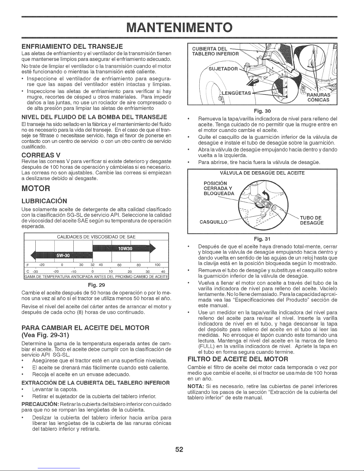
MANTENIMENTO
ENFRIAMIENTO DEL TRANSEJE
Las aletas de enfdamiento y e{ventilador de tatransmisi6n tienen
que mantenerse limpios para asegurar el enfriamiento adecuado.
No trate de Jimpiar el ventilador o la transmisi6n cuando el motor
este funcionando o mientras la transmisi6n este caliente.
Inspeccione el ventiJador de enfdamiento para asegura-
rse que las aspas del ventilador esten intactas y limpias.
Inspeccione las aJetas de enfriamiento para vedficar si hay
mugre, recortes de cesped u otros matedales. Para impedir
dahos alas juntas, no use un rociador de aire compresado o
de alta presi6n para limpiar las aletas de enfdamiento
NWEL DEL FLUIDO DE LA BOMBA DEL TRANSEJE
El transeje ha sido sellado en la f&bdca y el mantenimiento del fluido
no es necesado para la vida det transeje. En el caso de que eltram
seje se fiJtrase o necesitase servicio, haga el favor de ponerse en
contacto con un centro de servicio o con un otto centro de servicio
cuatificado.
CORREAS V
Revise las correas V para verificar si existe deterioro y desgaste
despu@s de 100 horas de operaci6n y c&mbielas si es necesario.
Las correas no son ajustabJes. Cambie las correas si empiezan
a deslizarse debido al desgaste.
MOTOR
LUBRJCAOION
Use sotamente aceite de detergente de alta calidad clasificado
con taclasificaci6n SGoSL de servicio API. Seleccione la calidad
de viscosidad del aceite SAE segOn su temperatura de operaci6n
esperada.
CAL_DADES DE VmSCOSmDAD DE SAE
F -20 0 30 32 40 60 80 100
C -310 -10 D 1'0 20 30 40
SAMA DE TEMPERATURA ANTICPADA ANTES DEL PROXIMO CAMBIO DE ACEITE
Fig. 29
Cambie e{ aceite despues de 50 horas de operaci6n o por Iome-
nos una vez al a_o si e{ tractor se utiliza menos 50 horas el aho.
Revise e{ nivel del aceite det c&rter antes de arrancar e{ motor y
despu@s de cada ocho (8) horas de uso continuado.
PARA CAMBIAR EL ACEITE DEL MOTOR
(Vea Fig. 29-31)
Determine la gama de la temperatura esperada antes de cam°
biar el aceite. Todo elaceite debe cumplir con la clasificaci6n de
servicio API SGoSL
AsegOrese que e{tractor este en una superficie nivelada.
El aceite se drenar& m&s f&cilmente cuando este caliente.
Recoja e{ aceite en un envase adecuado.
EXTRAOOK)N DE LA CUBIERTA DEL TABLERO iNFERIOR
* Levantar la capota.
Retirar el sujetador de la cubierta del tablero inferior.
PREOAUOJ6N: Retirar lacubierta deltabtero inferior con cuidado
para que no se rompan las lengOetas de la cubierta.
Deslizar la cubierta del tablero inferior hacia arriba para
liberar las lengOetas de la cubierta de las ranuras c6nicas
del tablero inferior y retirarla.
Fig. 30
* Remueva Jatapa/variJJa indicadora de nivel para relleno de{
aceite. Tenga cuidado de no permitir que la mugre entre en
el motor cuando cambie el aceite.
, Quite et casquillo de la guarnici6n inferior de la v&tvula de
desag0e e instale et tubo de desagQe sobre la guarnici6n.
, Abra lavaJvula de desagOe empujando hacia dentro y dando
vuelta a la izquierda.
, Para abrirse, tire hacia fuera la vaJvula de desagOe.
V,&LVULA DE DESAGUE DEL ACEITE
POSITION
CERRADA Y
BLOQUEADA
TUBO DE
CASQUILLOI_/-_,, _¢>_'_//J ./y' DESAGUE
Fig. 31
* Despues de que e{ aceite haya drenado totaFmente, cerrar
y bloquee la v&Ivula de desagOe empujando hacia dentro y
dando vue{ta en sentido de tas agujas de un reloj hasta que
la clavija est& en la posici6n bloqueada segOn Io mostrado.
* Remueva el tubo de desagOe y substituya e{ casquillo sobre
la guarnici6n inferior de la v&Ivula de desagOe.
* Vue{va a Ilenar e{ motor con aceite a trav@s del tubo de la
varitla indicadora de nivel para relleno del aceite. Vacie{o
lentamente. No JoIlene demasiado. Para la capacidad aproxio
mada vea las "Especificaciones del Producto" secci6n de
este manual.
* Use un medidor en la tapa/varilla indicadora del nivel para
reiJeno de{ aceite para revisar el nivel. Jnserte {a varilJa
indicadora de hive{ en el tubo, y haga descansar la tapa
de{ dep6sito para reiJeno det aceite en e{ tubo al leer las
medidas. No enrosque el tap6n cuando este tomando una
lectura. Mantenga e{ nive{ de{ aceite en la marca de Ileno
(FULL) en la varilla indicadora de nivel. Apdete la tapa en
el tubo en forma segura cuando termine.
FILTRO DE: ACEITE DEL MOTOR
Cambie e{ filtro de aceite del motor cada temporada ovez por
medio que cambie e{aceite, si e{tractor se usa m&sde 100 horas
en un aho.
NOTA: Si es necesario, retire Jas cubiertas de panet inferiores
utilizando los pasos de la secci6n "Extracci6n de la cubierta del
tablero inferior" de este manual.
52
Page 53

MANTENIMENTO
F_LTRO DEL A_RE
Su motor puede suffir averias y funcionar de manera incorrecta con
un fiJtrode{ aire sucio. De{e servicio al fittro deaire m&s a menudo
si se usa en condiciones potvorosas. Vea la manual de la motor.
LJMPiEZA DE LA PANTALLA DE AIRE
La pantalla de aire est& sobre el soplador de la toma de ake
que se ubica en Japarte superior del motor. La pantalla de aire
se debe mantener libre de suciedad y paja para evitar que el
motor se dahe por sobrecaJentamiento. Limpie con un cepillo
de alambre o con aire compdmido para retirar la suciedad y las
fibras de goma secas dificiles de quitar.
S_LENCIADOR
Inspeccione y cambie e{ silenciador corroido y e{amortiguador de
chispas (siviene equipado) pues pueden crear un peligro de incendio
y/o dahos.
BUJiA(S)
Oambie las bujia(s) al comienzo de cada temporada de siega o
despues de cada 100 horas deoperaci6n, Io que suceda pfimero.
El tipo de bujia y el ajuste de la abertura aparecen en "ESPECI-
FiCACIONES DEL PRODUCTO" secci6n de este manual.
SJSTEMA DE ENFF{IAMIENTO DE AIF{E
Para asegurar un enfriamiento adecuado, aseg0rese que la rejilla
de{cesped, lasaletas de enfdamiento, y otras superficies externas
del motor se mantengan limpias en todo momento.
Cada 100 horas de operaci6n (m&s a menudo bajo condiciones
extremadamente potvorosas o sucias), remueva la caja de{
ventilador y otras tapas de enfriamiento. Limpie las aletas de
enfdamiento y las superficies externas, seg0n sea necesario.
Aseg0rese que se vuelvan a instalar las tapas de enfriamiento.
AWSO: Si se opera Ja m&quina con una rejilla del cesped bloo
queada, sucia, o con las aletas de enfriamiento taponadas, y/o
las tapas de enfriamiento removidas se produck& daho en e{
motor debido al calentamiento excesivo.
FILTRO DE COMBUSTIBLE (Vea Fig. 32)
El filtro de combustible debe cambiarse una vez cada temporada.
Si e{ fiJtro de combustible se tapona, obstruyendo el ftujo del
combustible hacia e{ carburador, es necesario cambiarlo.
1. Con el motor frio, remueva e{ filtro y tapone las secciones de
la linea de combustible.
2. Ponga elfiltro de combustible nuevo en su posici6n en la linea
de combustible con la flecha seSaJando hacia el carburador.
3. Aseg0rese de que no hayan fugas en la Jinea del combustible
y que las grapas esten cotocadas en forma adecuada.
4. Inmediatamente limpie toda la gasotina derramada.
LIMPJEZA 0lea Fig. 33)
* Limpie todo material extraho del motor, la bateria, el asiento,
et puJido, etc.
* Limpie los desechos de la ptaca guia. Los desechos pueden
Jimitar el movimiento del eje del pedal del freno/embrague,
lo que har& que patine la correa y que se pierda la tracci6n.
PRECAUCl6N: Evite todos los puntos de
enganche y las piezas m6viles.
DEL
C _ //PEDAL
-- _ LIMPIAR PARTE
- i: SUPERIOR
/
PLAOA DE
i DIREOOt6N
/
/
$1STEMA DE DIRECCt0N, $ALPICADERO,
GUARDA-BARROS Y SEGADORA NO MOSTRADOS
Mantenga las superficies pulidas y las ruedas sin derrames
de gasolina, aceite, etc.
Proteja las superficies pintadas con cera tipo automotfiz.
Excepto por el puerto de Javado (si esta incluido), se recomienda
no utilizar una manguera de jardin ni el lavado a presi6n para
limpiar la parte externa de su tractor, a menos que el motor y la
transmisi6n esten cubiertos para protegedos det agua. Si entra
agua en el motor o ta transmisi6n se reducira la vida 0til del trac-
tor. UtiJice aire comprimido o un sopJador de hojas para retirar
el cesped, las hojas y la basura de la parte externa del tractor y
de la cortadora de cesped.
EMBRAGUE/FRENO
Fig. 33
]
FILTRODE _ // f-zj
Fig. 32
667
53
Page 54

MANTENIMENTO
PUERTO DE LAVADO DE LA CUBIERTA
(Vea Fig. 34)
La pJataforma del tractor est& equipada con un puerto de lavado
como parte del sistema de lavado de la plataforma. Se debe
utilizar despues de cada uso.
1. Meve el tractor a un lugar horizontal y despejado de su
cesped, Io bastante cerca de una boca de fiego como para
que Ilegue la manguera del jardin.
IMPORTANTE: AsegOrese de que laboca de descarga de{tractor
est& odentada LEJOS de su casa, garaje, coches aparcados, etc.
Quite laboca de ensacado o cubierta de mantillo si esta acoplada.
2. Mueva eJ control del embrague det accesorio a la posici6n
"DESENGANCHADO', ponga el freno de estacionamiento
y apague e{ motor.
3. Enrosque e{ adaptador de la boquitla (empaquetado con el
manual del operador del tractor) en el extremo de la manguera
del jardin.
4. Eche hacia atras la abrazadera de cierre del adaptador de la
boquilla y empuje este en el puerto de lavado de la cubierta
en el extremo izquierdo de la cubierta de la segadora. Suelte
la abrazadera de cierre para fijar el adaptador en la boquilla.
ADAPTADOR DE
BOQUILLA
/
F_g. 34
IMPORTANTE: Tire de la manguera para asegurarse de que la
conexi6n esta bien fija.
5. Abra la Ilave del agua.
6. Desde la posici6n de{ operador del tractor, vuelva a arrancar
el motor y ponga la palanca de aceIeraci6n en la posici6n
rapido (",_").
IMPORTANTE: Vuelva a revisar el area para asegurar que esta
despejada. AsegOrese de que no haya ni_os en el area mientras
limpia la plataforma.
7. Mueva et control del embrague del accesodo a la posici6n
"ENGANCHAR'. Mantengase en ta posici6n del operador con
la cubierta de corte acoptada hasta que la cubierta este limpia.
8. AsegQrese de que el control del embrague del accesorio este
en la posici6n "DESACTIVADO'. Apague el motor. Apague
el agua.
9. Tire hacia atras la abrazadera de cierre deI adaptador de la
boquilla para desconectar el adaptador del puerto de lavado
de la cubierta.
10. Lleve el tractor auna zona seca, preferentemente decemento
opavimentada. Mueva elcontrol del embrague del accesorio
a la posici6n "ENGANCHAR" para quitar el exceso de agua
y ayudar a que se seque antes de guardar et tractor.
roto o no est,, Ud. y otras personas estar_n ex-
ADVERTENClA: Si el accesorio de lavado est_
puestos a que la hoja rueslance aqueHos objetos
* Sustituya inmediatamente el accesorio de Ravado
* Tape todos mosorificios de la segadora con pernos
con los que entre en contactoo
roto o que falta antes de volver a usar Rasegadora.
y tuercas de seguridad.
54
Page 55

SERVICIO Y AJUSTES
ADVERTENCmA: PARA EVLTAR LESIONES SER_AS, ANTES DE DAR CUALQUbER SERVLCLO O DE
HACER AJUSTES:
e
Presione el pedal del embrague/freno completamente y aplique el freno de estacionamiento.
e
Ponga la palanca de control de movimiento en la posici6n de neutro (N)o
e
Ponga el embrague del accesorio en maposici6n desenganchado (DmSENGAGED).
e
Ponga la Have de ignici6n en maposici6n de apagado (STOP) y remu_vala.
e
Aseg5rese que mascuchiHas y que todas _aspartes movib_es se hayan detenido completamente.
e
Desconecte e_alambre de _abuj_a y p6ngalo en donde no pueda entrar en contacto con _sta.
/
PARA DESMONTAR LA CORTADORA DE CESPED
(Vea Fig. 35)
* Suelte e{embrague poni6ndolo en Japosid6n"DESACTIVAD©'.
* Haga segadora descender a su posici6n m&s baja.
* Retire la barra de tensi6n de la correa (K) de la barra de
sujeci6n (L).
&
| despacioo |
& DUIDADO: Una vez que se desconecten las pie-
• Haga girar el volante del tractor todo lo posible a la izquierda.
• Destice la cortadora per debajo del lade derecho del tractor.
ciona a resorteo Suj_teta con fuerza y su_lteta |
Retire la correa de la cortadora de la potea del embrague
e{ectrico (M).
Desconecte la pieza de uni6n anterior (E) de la cortadora -
retire el resorte de contenci6n y la arandela.
Per uno de los lades de la cortadora, desconecte e{ braze
de suspensi6n de la cortadora (A) det chasis y la pieza
de uni6n posterior (C) de la barra posterior de la corta-
dora (D) - retire los resortes de contenci6n y las arande{as.
Per e{ otto tado de la cortadora, desconecte e{ braze de
suspensi6n y la pieza de uni6n posterior.
zas de uni6n posteriores, Rapalanca elevadora
funcionar_ a resorteo Sujete con fuerza la patanca
elevadora a_ cambiar_a de posici6no
Per e{ lade derecho de la cortadora, desconecte la barra anti=
balanceo (S) de la barra posterior derecha de la cortadora
(D) - retire e{ resorte de contenci6n y la arande{a, y jale la
cortadora hacia usted hasta que la barra se salga del orificio
de la barra.
PARA mNSTALAR LA SEGADORA
Siga los procedimientos que se describen en 'qNSTA=LACI©N
DE LA SEGADORA Y DE LA CORREA DE IMPULSION" en la
secci6n de Montaje de este manual.
PARA REEMPLAZAR LA CORREA DE LA
CUCH_LLA DE LA SEGADORA (Vea Fig. 36)
DESMONTAJE DE LA CORREA DE LA SEGADORA
Estacione e{tractor en una superficie nivelada. Ponga elfreno
de mane.
Baje la palanca etevadara a la posici6n de m&s abajo.
Retire la barra de tensi6n de la correa (K) de la barra de
sujeci6n (L).
Suj_teta con fuerza y su_itela despacioo
• Quite los tornillos (P) de las cubiertas derecha e izquierda y
retire{as (Q).
• Quite toda suciedad y restos de hierbas que pueda haberse
acumulada alrededor de los dispositivos de recotecci6n y de
toda la superficie superior.
• Retire la correa de la potea det embrague e{ectrico (M), las
dos poteas de los dispositivos de recolecci6n (R) y las poteas
de Jospihones (V).
MONTAJE DE LA CORREA DE LA SEGADORA
Instale la correa pas&ndola alrededor de las poleas (R) y
alrededor de las poteas (V), come se muestra en la figura.
Pase la correa per encima de la potea del embrague (M).
IMPORTANTE: Verifique que la correa calce bien en todas las
ranuras de las poteas de la cortadora.
Vue{va a colocar las cubiertas derecha e izquierda (Q). Ajuste
bien todos los tornitlos.
Cotoque la barra de tensi6n de la correa (K) en la barra de
sujeci6n (L).
1 _ CUIDA_'DO:Labarradetensidnfuncionaaresorteo r_
Suj_tela con fuerza y su_ltela despacioo
Suba la palanca etevadora a la posici6n de m&s arriba.
F_g. 35
F_g. 36
55
Page 56

SERVJCJO Y AJUSTES
PARA NWELAR LA SEGADORA
AsegQrese de que los neum&ticos esten inflados a JaPSI que se
indica en estos. Si est&n demasiado inflados o poco inflados,
eJc@sped no le quedara bien cortado, Io cual podra IlevarJo a
pensar que la segadora no esta bien reguJada.
REGULACK)N VISUAL DE LADO A LADO (Vea Fig. 37)
* Si todos Jos neum&ticos est&n correctamente inflados y eJ
cesped parece haber quedado cortado desparejo, determine
que Jado de la cortadora esta cortando m&s al ras.
Con una flave ingtesa de 3/4" o de calibre regutable, haga
girar hacia la izquierda latuerca de ajuste de Japieza de uni6n
(A) para bajar Jadoizquierdo Jacortadora, o bien hagala girar
hacia lado derecho la derecha para subirJa.
HAGA GJRAR LA
TUERCA HACtA
LA DERECHA
PARA SUBIR LA
SEGADORA
Fig. 37
HAGA GJRAR LA
TUERCA HACIA
LA IZQUIERDA
PARA BAJAR LA
SEGADORA
NOTA: Cada vueJta completa de Jatuerca de ajuste harA variar
la altura de la cortadora aproximadamente 4,7 mm (3/16").
Pruebe la regulaci6n realizada cortando cesped que a[3n no
haya cortado y observando c6mo queda. VueJva a ajustar,
en caso necesario, hasta obtener resuJtados satisfactorios.
REGULACtON DE LA PRECISION DE LADO A LADO
(Yea Fig. 38)
* Con todos los neum&ticos correctamente inflados, estacione
el tractor a niveJdel sueJo o en la entrada a la casa.
i OUtDADO: Las cuchiHas son afHadaso Prot_jase Jas|
manos con guantes o envue{va _as cuchiHas con|
tela gruesa, o bien haga ambas cosaso
* Suba la segadora a la posici6n m&s aJta.
* A ambos lados de Ja cortadora, ubique la cuchiJla hacia un
lado y mida la distancia (A) que hay entre el borde inferior
de la cuchiJla y el sueJo. Dicha distancia debe set la misma a
ambos lados.
* En caso que sea necesario realizar un ajuste, lea los paso 2
de Jasinstrucciones de Regulaci6n Visual que aparecen mas
arriba.
* Vuelva a verificar las medidas y ajuste nuevamente, en caso
necesario, hasta que ambos lados queden iguales.
I A
AJUSTE DE DELANTE A ARRAS (Yea Fig. 39 y 40)
JMPORTANTE: El piso debe quedar bien niveJado de Jadoa lado.
Para que el cesped le quede perfectamente cortado, Jascuchil-
las de la cortadora deben ajustarse de tal manera que la punta
anterior quede 3,1 a 12,7 mm (1/8" a 1/2") mas abajo que Japunta
posterior cuando Jacortadora se encuentre ensu posici6n mas alta.
OUtDADO: Las cuchiHas son afHadas. Prot6jase Jas
manos con guantes o envueJva _ascuchiHas con
teta gruesa, o bien haga ambas cosaso
Suba la segadora a la posici6n m&s alta.
Ubique cualquiera de Jas hojas de la cuchilla de tal manera
que la punta quede apuntando directamente hacia adeJante.
Mida la distancia (B) que hay entre la punta anterior y eJsueJo
y entre la punta posterior y eJsuelo.
Fig. 39
Si lapuntaanterior dela hoja de la cuchi{la no est&3,1 a12,7mm
(1/8" a 1/2") m&s abajo que la punta posterior, dirijase a la
parte de adeJante del tractor.
Con una Ilave inglesa de 11/16" o de calibre reguJable, afloje
la tuerca A, d&ndole varias vueltas para despejar la tuerca
de ajuste B.
Con una Ilave ajustable de 3/4", gire la tuerca de ajuste de
esJab6n frontal (B) hacia Jaderecha (F_) (apriete) para eJevar
eJfrente de la cortadora de cesped, o hacia Jaizquierda (_)
(afloje) para bajar eJfrente de la cortadora de cesped.
t
AJUSTE LA TUERCA
DE REGULAOION
DE ALTURA "B" _ ii
PARA LEVANTAR
LA SEGADORA
AFLOJELATUERCA"A"PRIMERO
AFLOJE LA TUERCA
DEREGULACI6N
DE ALTURA"B"
PARA BAJAR
LA SEGADORA
Fig. 40
NOTA: Cada vueJta comp{eta de Jatuerca de ajuste har& variar
la altura de la cortadora 3,1 mm (1/8").
Vue{va a verificar las medidas y ajuste nuevamente, en caso
necesario, hasta que Japunta anterior de la hoja de Jacuchifla
quede 3,1 a 12,7 mm (1/8" a 1/2") m&s abajo que Ja punta
posterior.
Mantenga en la posici6n Iatuerca de ajuste por medio de una
Ilave inglesa, y apriete bien Jatuerca contra dicha tuerca de
ajuste.
F_g. 38
56
Page 57

SERVlCIO Y AJUSTES
PARA CAMBIAR LA CORREA DE IMPULSION DE
MOVlMIENTO (Vea Fig. 41)
Estacione el tractor en una superficie nivetada. Ponga el freno
de mano. Si necesita asistencia, del lade de abajo det apoyapi6s
izquierdo hay una guia pr&ctica para el montaje de la correa
DESMONTAJE DE LA CORREA
1. Desmonte la segador& (Ver "PARA DESMONTAR La sega-
dora en este capitulo del manual.)
NOTE: Observe toda la correa de impulsi6n de movimiento y la
posici6n de todas las guias y guardacorreas.
2. Desconecte et arnes det cable det embrague (A).
3. Quite la pieza de uni6n anti-rotaci6n (B) que esta del lado
derecho det tractor.
4. Retire la correa det pifl6n estacionario (C) y del pifl6n del
embrague (D).
5. Retire la correa del pifl6n central (E).
6. Jale el cable de la correa hacia la parte de atras det tractor.
Con mucho cuidado, retire la correa jalando hacia arriba
desde la polea de entrada de ta transmisi6n y por encima de
las paletas del ventilador (F).
7. Retire la correa jalando hacia abajo desde la potea det motor
y alrededor det embrague electrico (G).
8. Destice la correa hacia la parte de atras del tractor, retirela
de la placa de direcci6n (H) y saquela del tractor.
MONTAJE DE LA CORREA
1. Instale la correa nueva pas&ndota de la parte de atr&s a la
parte de adelante del tractor, por encima de la placa de direc-
ci6n (H) y del vastago del pedal del embrague / freno (J).
2. Jale la correa hacia la parte de adelante del tractor y pasela
alrededor del embrague y por sobre la potea del motor (G).
3. Jale la correa hacia la parte de atras del tractor. Con mucho
cuidado, pase la correa de arriba a abajo alrededor del ven°
tilador de transmisi6n y per sobre la potea de entrada (F).
Aseg0rese de que la correa este dentro del guardacorrea.
4. Monte la correa en el pifl6n central (E).
5. Paseta a traves del pifi6n estacionario (C) y del pifi6n del
embrague (D).
6. Vuetva a instalar la pieza de uni6n anti-rotaci6n (B) del lado
derecho del tractor. Aj0stela bien.
7. Vuelva a conectar et arnes del embrague (A).
8. AsegOrese de que la correa calce en todas las ranuras de las
poleas y dentro de todas las guias y guardacorreas.
9. Monte la segadora. (Mer 'qNSTALE LA SEGADOR,_' en este
capitulo del manual.)
/
Fig. 41
CONTROLAR Y AJUSTAR EL FRENO
Si el tractor exige m&s de 1,5 m (cinco (5) pies) para pararse a
una velocidad m&s alta en el cambio m&s alto en una superficie
nivelada de hormig6n seco o pavimentada, entonces se debe
controtar y ajustar el freno.
CONTROL DEL FRENO
1. Aparcar el tractor en una superficie nivetada de hormig6n
seco o pavimentada, presionar el pedal del freno hasta el
fondo y accionar el freno de estacionamiento.
2. Desembragar latransmisi6n colocando etmando de la rueda
libre en la posici6n "transmisi6n desembragada". Tirar el
mando de la rueda libre fuera y dentro la ranura y sottar asi
se coloca en la posici6n desembragada.
Las ruedas traseras tiene que btoquearse y patinar cuando se
intenta empujar hacia adelante el tractor manualmente. Sustituir
las zapatas delfreno ocontactar otro centro de servicio cualificado.
CONVERGENCIAilNCLINACION DE LAS RUEDAS
DELANTERAS
La convergencia y la inclinaci6n de las ruedas delanteras
no son ajustables en su tractor. Si ha sufddo daho como
para afectar la convergencia o la inctinaci6n de las ruedas
delanteras, p6ngase en contacto con un otro centro de
servicio cualificado.
57
Page 58

SERVICIO Y AJUSTES
PARA REMOVER LAS RUEDAS (Vea Fig. 42)
* BIoquee e{ eje en forma segura.
* Remueva la cubierta del eje, e{ aniJlo de retenci6n y las
arandelas para permitir la remoci6n de las ruedas (la rueda
trasera contbne una Ilave cuadrada °no la pbrda).
* Repare la Ilanta y vuelvala a montar.
AVlSO: En las ruedas traseras sotamente: a{inee las ranuras en
el cubo de la rueda trasera en el eje. Inserte la Ilave cuadrada.
* Vuelva a cobcar las arandelas e inserte e{anillo de retenci6n
en forma segura en la ranura del eje.
* Vueiva a colocar la cubierta de{ eje.
AWSO: Para arregtar las Ilantas perforadas y p@a prevenir que
tenga Ilantas pinchadas a causa de pequeSas fugas, comprar de
su commerciante y utilizar e{ selto para Ilantas. EIseilo previene
que las Ilantas se sequen y tambien la corrosi6n.
ARANDELAS
ANILLO DE
RETENCt6N
CUBIERTA
DEL EJE
LLAVE
RUEDA TRASERA SOLAMENTE)----_.- -_1
Fig. 42
REGULACION DE LA PALANCA DE CONTROL DEL
MOVIMIENTO NEUTRO DEL CAMBIO MECANICO
(Yea Fig. 43)
La palanca de control del movimiento de{ cambio mec&nico ya
viene predefinida por la Casa constructora y por Io tanto no re-
quiere ultedores regutaciones.
1. Aflojar ligeramente el perno de regulaci6n en la parte anterior
de la rueda posterior derecha;
2. Porter en marcha el motor y mover la palanca de control
det movimbnto del cambio mecanico hasta Ilevarla en una
posici6n en la que no se pueda mover ni adelante ni atras;
3. Mantener la palanca de control de{ movimiento del cambio
mecanico en esta posici6n y apagar el motor;
4. Manteniendo la palanca en la posici6n arriba indicada, aftojar
el perno de regutaci6n;
5. Mover lapalanca de control del movimiento en posici6n neutro
(cierre metatico);
6. Enroscar bien el perno de regulaci6n.
AVISO: Desptazar el piano de trabajo de la segadora hasta la
posici6n mas baja para aumentar el juego al fin de acceder al
perno de regulaci6n.
Si el tractor sigue destizandose adelante y atras, despues de
esta re.gulaci6n y con la palanca en posici6n neutro, efectuar las
operaclones indicadas de seguida.
1. Aflojar el perno de regulaci6n.
2. Mover lapalanca de control del movimiento de 1/4 o 1/2 pulgar
(6.3 o 12.7 mm) en la direcci6n de deslizambnto.
3. Enroscar bien el perno de regutaci6n.
4. Porter en marcha el motor y probarlo.
5. Si el tractor sigue deslizando, repetir las operaciones arriba
indicadas hasta alcanzar los resultados deseados.
PALANCA DE CONTROL
DE
PERNO DE
VELOCtDADES
Fig. 43
PARA HACER ARRANCAR EL MOTOR CON UNA
BATERiA BAJA (Vea Fig. 44)
ADVERTENCIA: Las bater_as de _cido-plo-
mo generan gases explosivos. Mantenga
las chispas, RasHamas y _osmateriales para
fumar alejados de Rasbaterias. Siempre use
una protecci6n para los ojos alrededor de
las bater_aso
Si su bateria est& demasiado baja como para hacer arrancar el
motor tiene que votverse a cargar. (Vea "BATER[,_' en la secci6n
de Mantenimiento de este manual).
Si se usan "cables de empalme" para un arranque de emergeno
cia, siga este procedimiento:
IMPORTANTE: SU TRACTOR ESTA EQUPADO CON UN SISTE-
MA DE 12 VOLTS. EL OTRO VEH[CULO TAMBIEN TENE QUE
TENER UN SISTEMA DE 12VOLTS. NO USE LA BATER[A DE SU
TRACTOR PARA HACER ARRANCAR A OTROS VEH[CULOS.
PARA ADJUNTAR LOS CABLES DE EMPALME -
Conecte cada extremo del cable ROJO con elterminal (A-B)
POSITIVO (+) de cada bated& preocup&ndose de no hacer
cortocircuito en el chasis.
Conecte un extremo del cable NEGRO con el terminal (C)
NEGATWO (o) de una bateria comptetamente cargada.
Conecte el otro extremo del cable (D) NEGRO con un buena
CONEXI©N A TERRA DEL CHASIS, alejado del estanque
de combustible y de la bateria.
m
F-q
BATERiA DEBIL
O DESCARGADA
BATERiA COMPLETAMENTE
CARGADA
Fig. 44
58
Page 59

SEF{VICIO Y AJUSTES
PARA REMOVER LOS CABLES, INMIERTA EL ORDEN
El cable NEGRO primero del chasis y luego de la bateria
comptetamente cargada.
El cable ROJO al Ott[mode ambas baterias.
REEMPLAZAR LA BATER_A (Vea Fig. 45)
ADVERTENOIA: No haga cortocircuito con los
terminalee de Re bateria al permit[r que una
Have de tuerca o cualquier otto objeto entre
en contacto con amboe terminalee a la miema
vezo Antes de inetalar _abater_a remueva Rae
pumeerae de metal, los re_ojee de puleera de
metal, los anilloe, etc. El terminal poeitivo tiene
que conectaree primero para evitar Raechiepae
debido a _aconexi6n a tierra pot accidenteo
Levantamos la capota a la posici6n levantada.
Desconecte el cable de ta bateria NEGRO pr[mero y luego
e{ cable de la bateria ROJO y remueva la bateria del tractor.
Instale la nueva bateria con losterminos en misma posici6n
como la bateria vieja.
Reemplazamos cub[erta terminal.
Primero, conecte elcable de la bateria ROJO con e{terminal
posit[vo (+) con e{ perno hexagonal y la tuerca seg0n se
muestra. Apr[etelos en forma segura.
Conecte el cable de conexi6n a tierra NEGRO al terminal
negat[vo (°)con e{ perno hexagonal y la tuerca que queden.
Apr[etelos en forma segura.
Cerramos la capota.
PARA REMOVER EL CONJUNTO DEL CAPO Y
DEL ENREJADO (Vea Fig. 46)
1. Levante el cap6.
2. Desabroche et conector del alambre de las luces delanteras.
3. P&rese delante de{ tractor. Agarre el cap6 en los lados, [n-
clinelo un poco hacia e{ motor y saquelo del tractor.
4. Para volver a instalarel cap6, aseg0rese de votver a conectar
e{ conector del alambre de las luces.
CAPOTA
CONECTOR
DELALAMBRE
DE LAS LUCES
DELANTERAS
F_g. 45
PARA CAMB_AR LA BOMB_LLA DE LA LUZ DEL-
ANTERA
1. Levante el cap6.
2. Tire el sujetador de la bomb[lla fuera del agujero en la parte
trasera del enrejado.
3. Cambie la bomb[tla en e{ sujetador y empuje el sujetador de
la bombilla, en forma segura, hac[a atras en e{agujero en la
parte trasera del enrejado.
4. Cierre el cap6.
ENTREC_ERRE Y RELES
El alambrado suelto o da_iado puede producir e{ mal funcio-
namiento de su tractor, o que deje de funcionar, o le [mpida e{
arrancar.
* Revise e{ alambrado.
Fig. 46
REMOC_6NiREEMPLAZO DE: LA TRANSMISI6N
Si pot acaso su transmisi6n debe set removida para servicio o
reemplazo, debe ser purgada despues de lareinstalac[6n y antes
de operar el tractor. Vea "PURGAR LA TRANSMISION" en la
secci6n de la Operac[6n de este manual.
MOTOR
PARA AJUSTAR EL CABLE DE CONTROL DE LA
ACELERACI(')N
El control de la ace{eraci6n ha s[do preajustado en laf&brica y no
deberia neces[tar ajustes. Revise los ajustes que se descdben a
confinuac[6n, antes de sottar eJcable. Si eJajuste es necesario,
vea de manual de motor.
PARA AJUSTAR EL CONTROL DE ESTRANG ULAC_6N
El control de la estrangulaci6n ha sido preajustado en lafabrica
y no deberia necesitar ajustes.
PARA CAMBIAR EL FUSIBLE
C&mb[elo por un fusible t[po enchufable de 30 amps, t[po auto-
motr[z. El sujetador del fusible est& ub[cado detr&s del tablero.
59
Page 60

ALMACENAMIENTO
Inmediatamente prepare sutractor para el almacenamiento al final
de la temporada o si el tractor no se va a usar per 30 dias o m&s.
Advertencia: Nunca almacene el tractor con
gasoJina en el eatanque dentro de un edificio
en donde Boa gases pueden alcanzar una
llama expueata o una chiapa° Permita que
el motor se enfHe antes de almacenarlo en
cualquier recinto privado.
Remueva la segadora deJtractor para e{a{macenamiento por el
invierno. Cuando tasegadora se va aalmacenar per cierto periodo
de fiempo, limpieta cuidadosamente, quite toda la mugre, lagrasa,
las hojas, etc. Guardela en una area limpia y seca.
Limpie todo el tractor. (Vea "LIMPiEZ_' en la secci6n de
Mantenimiento en este manual.)
Inspeccione y cambie las correas, sies necesado. (Vea las
instrucciones para el cambio de las correas en la secci6n
de Servicio y Ajustes de este manual.)
Lubriqueto, seg0n se muestra en lasecci6n de Mantenimiento
de este manual.
Aseg0rese que todas Jas tuercas, los pernos y los tornillos
est@n sujetados en forma segura. Inspeccione las partes
movibles para vedficar si hay daho, rotura o desgaste.
Cambielas sies necesario.
Retoque todas superficies pintadas oxidadas o picadas;
aplique lija antes de pintar.
Cargue la bateria comptetamente antes de guardarla.
Despues de cierto periodo de tiempo en almacenamiento,
la bateria puede necesitar votver a cargarse.
Para ayudar a evitar la corrosi6n y las fugas de potencia
durante largos periodos de almacenamiento, se deben
desconectar los cables de Jabateria y se debe limpiar cui-
dadosamente. (Vea "PARA UMPJAR LA BATERIA Y LOS
TERMINALES" en la secci6n de Mantenimientode este
manual.)
Despues de Jimpiarla, deje los cables desconectados y
p6ngalos en donde no puedan entrar en contacto con los
terminales de la bateria.
Si se remueve la bateria de{ tractor para e{almacenoamiento,
no laguarde directamente sobre concrete osobre superficies
h0medas.
Si launidad est& equipada con indicador de bateria/conector
de carga, se puede adquirir una unidad de carga opcional
y conectarse a la unidad para cargar la bateria durante
un almacenamiento protongado. Inspeccione y limpie las
terminales de la bateria conforme sea necesario antes de
aJmacenarse durante un tiempo protongado con el cargador
conectado.
MOTOR
SISTEMA DE COMBUSTIBLE
IMPORTANTE: Es important evitar que se forman depositos
de goma en partes fundamentales del sistema de combusotible
tales como el carburador, el filtro de{ combustible, la manguera
del combustibles mezclados con alcohol (conocido como gasohol
o que tienen etanol o metanot) pueden atraer humedad, Joque
conduce a Ja separaci6n y a la formaci6n de acudos durante
etalmacenamiento. La gasolina acidica puede dahar el sistema de
combustible de un motor durante el periodo de almacenamiento.
Vaciar el dep6sito del carburante poniendo en marcha el
motor y dejandolo funcionar hasta que elcarburante termine
el carburador este vacio.
Nunca use Jos productos para limpieza del carburador o
del motor en el estanque de combustible pues se pueden
producir dahos permanentes.
Use combustible nuevo la pr6xima temporada.
AVJSO: El estabilizador de combustible es una aJternativa acepta-
ble para reducir a un minimo laformaci6n de dep6sitos de goma
en el combustible durante el periodo de aJmacenamiento. Agregue
estabilizador a la gasotina en el estanque de combustible o en el
envase para et almacenamiento. Siempre siga la proporci6n de
mezcla que se encuentra en el envase del estabilizador. Haga
funcionar el motor por Io menos 10 minutes despues de agregar
el estabilizador, para permitir que este Jlegue al carburador. No
vaciar la gasotina del estanque de gasoJina y el carburador si se
esta usando estabilizador de combustible.
ACEITE DEL MOTOR
Drene el aceite (con el motor caliente) y c&mbielo con aceite de
motor limpio. (Vea"MOTOR" en la secci6n de "MANTENJMJENTO"
de este manual.)
ClLJNDRO(S)
Remueva la(s) bujia(s).
Vacie 29.5 mL (1 Oz.) de aceite a traves del agujero(s) de
la bujia en el citindro(s).
Gire la IJave de ignici6n a la posici6n de 'ARRANQUE"
(START), per unos cuantos segundos para distribuir elaceite.
Cambie per bujia(s) nueva(s).
OTROS
No guarde la gasotina de una temporada a la otra.
Cambie et envase de lagasolina si se empieza a oxidar. La
oxidaci6n y/o lamugre en su gasotina produciran problemas.
Si es posible, guarde su unidad en un recinto cerrado y
c0brala para protegeda contra el potvo y la mugre.
Cubra su unidad con un forro protector adecuado que no
retenga la humedad. No use pJastico. El plastico no puede
respirar, Jo que permite la formaci6n de condensaci6n, Io
que producira la oxidaci6n de su unidad.
IMPORTANTE: NUNCA CUBRA EL TRACTOR MENTRAS
EL MOTOR Y LAS AREAS DE ESCAPE TODAV[A ESTAN
CAMENTES.
6O
Page 61

y
IDENTIFICACION PROBLEMAS
PROBLEMA
m
No arranoa
Dificil de arrancar
El motor no la vuelta
El motor suena pero
no arranoa
P6rdida de fuerza
Vibrac[6n
exoesiva
CAUSA
1. Sin combustible.
2. Motor sin la"ESTRANGULACI(DN" (CHOKE)
adecuada.
3. Motor ahogado.
4. Bujia male.
5. Filtro de aire sucio.
6. Filtro de combustible sucio.
7. Ague en el combustible.
8. Alambrado suelto o de,ado.
9. Valvulas del motor desajustadas.
1. Filtro de aire sucio.
2. Bu}ia male.
3. Bateria baja o descargada.
4. Filtro de combustible sucio.
5. Combustible rancio o sucio.
6. AJambrado suelto o de,ado.
7. V&lvu!asde! motor desajustadas.
1. Pedal del freno no presionado.
2. El embrague del accesorio esta enganchado.
3. Bateria baja o descargada.
4. Fusible quemado.
5. Terminales de la bateria corroidos.
6. Alambrado suelto o de,ado.
7. Hnterruptor de la ignici6n fallado.
8. Solenoide o arrancador fallados.
9. Interruptor(es) que exige(n) la presencia del
operador fallado.
1. Bateria baja o descargada
2. Terminales de la bateria corroidos.
3. Alambrado suelto o de,ado.
4. Solenoide o arrancador fallados.
1. Corta mucho cesped, muy rapido.
2. Aceleraci6n en la posici6n de "ESTRANGU=
LACION" (CHOKE).
3. Acumulaci6n de cesped, hojas y basura debajo
de la segadora.
4. Filtro de aire sucio.
5. Nivel de aceite bajo/aceite sucio.
6. Bujia fallada.
7. Filtro de combustible sucio.
8. Combustible rancio o sucio.
9. Ague en el combustible.
10. Alambrado de la bujia suelto.
11. Rejilla/aletas de aire del motor sucias.
12. Silenciador sucio/taponado.
13. Alambrado suelto o de,ado.
14. Valvulas del motor desajustadas.
1. Cuchilla desgastada, doblada o suelta.
2. Mandril de la cuchilla doblado.
3. Parte(s) suelta(s)/dai_ada(s).
CORRECCK)N
1, Llene el estanque de combustible,
2, Yea "PARA HACER ARRANCAR EL MOTOR" en la seco
ci6n de operaci6n.
3. Espere varios minutos antes detratar de arrancar.
4. Cambie la buj[a.
5. Limpie/cambie el filtro de aire.
6. Cambie el filtro de combustible.
7. Vaciar el estanque de combustible y el carburador, vuelva
a Ilenar el estanque con gasoline nueva cambie el filtro de
combustible.
8. Revise todo el alambrado.
9. Pongase en contacto con un centro de servicio cuali o
ficado.
1. Limpie/cambie el filtro de aire.
2. Cambie la bujia.
3. Vuelva a cargar o cambie la bateria.
4. Cambie el filtro de combustible.
5. Vaciar el estanque de combustible y vuelva a Ilenarlo con
gasoline nueva.
6. Revise todo el alambrado.
7. Pongase en contacto con un centro de servicio cualificado.
1. Presione el pedal del freno.
2. Desenganche el embrague del accesorio.
3. Vuelva a cargar o cambie la bateria.
4. Cambie el fusible.
5. Limpie los terminales de la bateria.
6. Revise todo el alambrado.
7. Revise/cambie el interruptor de la ignici6n.
8. Revise/cambie el solenoide o arrancador.
9. P6ngase en contacto con un centro de servicio cuali o
ficado.
1. Vuelva a cargar o cambie la bater[a.
2. Limpie los terminales de la bateria.
3. Revise todo el alambrado.
4. Revise/cambie el solenoide o arrancador.
1. Eleve la altura de corte/reduzca la velocidad
2. Ajuste el control de la aceleraci6n.
3. Limpie la parte inferior de la cajade la segadora.
4. Limpie/cambie el filtro de aire.
5. Revise el nivel de aceite/cambie el aceite.
6. Limpie y vuelva a ajustar la abertura o cambie la bujia.
7. Cambie el filtro de combustible.
8. Vaciar el estanque de combustible y vuelva a Ilenarlo con
gasoline nueva.
9. Vaciar el estanque de combustible y el carburador, vuelva
a Ilenar el estanque con gasoline nueva y cambie el filtro
de combustible.
10. Conecte y apriete el alambre de la bujia.
11. Limpie las rejilla/aletas de aire del motor.
12. Limpie/cambie el silenciador.
13. Revise todo el alambrado.
14. Pongase en contacto con un centro de servicio cuali o
ficado.
1. Cambie la cuchilla. Apriete el perno de la cuchilla.
2. Cambie la mandril de la cuchilla.
3. Apriete la(s) parte(s). Cambie las partes decades.
81
Page 62

f
JDENTJFJCACJON DE PROBLEMAS
PROBLEMA
El motor continua
funcionando cuando
et operador se baja
del asiento con el
embrague del acces-
orio enganchado
r
EJ corte disparejo
Las cuchiHas sega-
doras no rotan
MaJa descarga del
c_sped
Las luz(ces)de
lantera(s)no
funcionando
La bater_a no carga
P6rdida de
impuJsi6n
EJ motor tJene "con°
traexplosiones"
cuando se "APAGA"
r
El tractor se ponen
marcha atr_s
CAUSA
1, Sistema de control que exige la presencia deJ
operador -seguddad fallado,
1. Cuchilla desgastada, doblada o suelta.
2. El conjunto segador no estanivelado.
3. AcumulacJ6n de cesped, hojas y basura debajo
de la segadora.
4. Mandril de la cuchilJa doblado.
5. Los agujeros de ventiJaci6n del con]unto sega o
dor taponadosdebido ala acumulaci6n dece-
s ed_ los mandriJes.
1. Obstrucci6n en el mecanismo del embrague.
2. La correa de impulsi6n de la segadora esta
desgastada/da_ada.
3. Polea de guia atascada.
4. Mandril de la cuchilla atascado.
1. Velocidad del motor muy lent&
2. Velocidad de recorrido demasiado rapida.
3. Oesped mojado.
4. El conjunto segador no estanivelado.
5. Presi6n de aire de las IJantas baja o dispareja.
6. CuchiJla desgastada, doblada o suelta.
7. AcumulacJ6n de cesped, hojas y basura debajo
de la segadora.
8. La correa de impulsi6n de la segadora esta des°
gastada o desajustada.
9. Las cuchillas estan mal coninstaladas.
10. Cuchillas inadecuadas en uso.
11. Los agujeros de ventilaci6n del conjunto agujeros
segador taponados debido a la acumuJaci6n de
cesped, hojas y basura alrededor de los mandriles.
1. El interruptor esta'APAGADO"(OFF).
2. BombiJla(s) o Jampara(s) quemada(s).
3. Interruptor de la luz fallado.
4. AJambrado suelto o de,ado.
5. Fusible quemado.
1. Elemento(s) de la bateria male(s).
2. Maias conexiones de cables.
3. Regulador fallado (si equipado).
4. Akernador fallado.
1. El control de rueda libre esta enla posici6n
"DESENGANCHADO" (disengaged).
2. Residuos es en de la place de direcci6n. (Si los
tiene)
3. Lacorrea de impulsi6n deimpulsi6n de movimiento.
4. Aire atrapado en Jatransporte o el servicio.
5. Llave cuadrada de eje es ausente.
1, El control de la aceJeraci6n del motor no fue
ajustado en la posici6n de velocidad media y
maxima (rapida) antes de pare el motor,
1. El sistemade funcionamiento atras (ROS) no esta
"ON",cuando enganchelasegadoraootroaccesorio.
CORRECCm6N
1, Revise el alambrado, los interruptores y la conexiones,Si
no estan correctas, pongase en contacto con un centro
de servicio cualificado,
PRECAUCI6N: NO Jamaquina sino hasta haber
corregido el probMema.
1. Cambie la cuchilla. Apriete el pemo de la cuchilla.
2. Nivele el conjunto segadoK
3. Limpie la parte inferior de la cajade la segadora.
4. Cambie la mandril de la cuchilJa.
5. Limpie alrededor de los mandriles pare abdr los de
ventiJaci6n.
1. Remueva la obstrucci6n.
2. Cambie la correa de impulsi6n de la segadora.
3. Cambie la polea de guia.
4. Cambie la mandril de la cuchilla.
1. Ponga el control de la aceleraci6n en la posici6n de
"RAPIDO" (fast).
2. Cambie a una veJocidad mas lenta.
3. Permita que se seque el cespedantes de segar.
4. Nivele el conjunto segadoK
5. Revise las Ilantas pare verificarque tienen la presi6n de aire.
6. Cambie/afile la cuchilla. Apriete el perno de la cuchilia.
7. Limpie la parte inferior de la cajade la segadora.
8. Cambie/ajuste la correa de impulsi6n de la segadora.
9. Vuelva a instaJar las cuchilJes eJbordeafiJadohacia abaio.
10. Cambie por las cuchilJas enumeradas en este manual.
11. Limpie alrededor de los mandriles pare abdr los de
ventiJaci6n.
1. "ENCIEND£' (ON) el interruptor.
2. Cambie la bombilla(s) o I&mpara(s).
3. Revise/cambie el interruptor de la luz.
4. Revise e! alambrado y las conexiones.
5. Cambie el fusible.
1. Cambie la bateria.
2. Revise/limpie todas las cables.
3. Cambie el regulador.
4. Cambie el altemador.
1. Ponga el control de rueda libre enla posici6n
"ENGANC HADO"(disengaged).
2. Vea "LIMPIEZ_' en la secci6n de Mantenimento de este
manual.
3. Reemplace la correa de movimJen-to esta gastada, daSada
o rot&
4. Purgue Jatransmisi6n.
5. Vea "PARA REMOVER LAS RUEDAS" en Jasecci6n de
Servicio y Ajustes de este manual.
1. Mueva el control de JaaceJeraci6n ala posici6n de veloci o
dad media y maxima (rapida) antes de pare el motor.
1. GJrar el ROSen la posici6n "ON".Vea la secci6n de
operaci6n.
opera
62
Page 63

GUiA SUGERIDA PARA MEDIRLAS PENDIENTESCON LAVISTA PARA UNA
OPERACIONSEGURA
SOLAMENTE ANDE CUESTA ARRIBA O
CUESTA ABAJO Y NO ATRAViESE EL CERRO
15 GRADOS MAX,
1. Plegar esta p_gina a to largo de la !inea punteada arriba indicada.
2. Tenet la pagina ante de el mismos de modo que su horde izquierdo sea vertical
para_elo al tronco del arbol u otra estructura vertica!.
3. Mirar a tray,s del piiegue en direcci6n de la pendiente que ee quiere medir.
4. Comparar el _ngulo del pHegue con la pendiente del terreno.
Page 64

Productos de consumo equipados con ruedas - Garant_a ]imitada
Husqvama garantiza al comprador minorista original clue este producto Husqvama:_' carece de defectos materiales o de fabr%acidn para un uso y mantenimiento
nom_ales desde el dia de la compra, dentro del periodo de garantia aplicable indicado en el Anexo A. Esta Garantia limitada no se po&fi transfzrir a ningim comprador
posterior de este producto Husqvarnaa;'. Ciertos componentes (pot ejemplo, los motores y las transmisiones) qnedan excluidos de la coberttlra y se aplican otras
limitaciones, segim se describe en este documento Husqvama repararfi o sustimirfi, segim su criterio y sin cargo algtmo, cualquier prodncto o pieza del_cmoso cubierto
por la Garantia limitada, en cualquier concesionario/centro de servicio Husqvama autorizado, utilizando repuestos originales de OEM Husqvama, de conlbm3idad con
las limitaciones y exclusiones que se describen a continuacidn Husqvama no ofi'ece programa de cambio directo
EXCENCTONES, LIMITACIONES Y EXCL[ SIONES
1 EXENCTON DE GARANTJ_A. ESTA GARANTIA LIMITADA ES LA (_ICA GARANTIA EXPLICITA PROPORCIONADA POR HUSQVAbL'<A, Y NO EXISTEN
OTRAS GARANT][AS EXCEPTO LAS AQU][ EXPUESTAS, SALVO LAS QUE P__EDA ESTABLECER LA LEY ESTA GARANT][A SOLO ESTJ_ PROPORCIONADA
POR HUSQVARNA Y SOLO HI_ SQVARNA LA PUEDE MODIFICAR ESTA GARANTIA LIMITADA ES LA MANIFESTACI()N FINAL DE NI_ ESTRO ACUERDO, Y
ES UNA DECLARACION COMPLETA Y EXCLUSIVA DE LAS CONDICIONES DE DICHO ACUERDO ESTA GARANTIA LIMITADA LE OTORGA DERECHOS
LEOALES ESPECIFICOS_ AUNQUE TAMBI]_N PUEDE TENER OTROS DERECHOS DEPENDIENDO DE LA UBICACION
2. DURACION LIMITADA. CUALQUIER GARANTIA QUE PUEDA SER IMPLICITA DE ACUERDO CON LAS LEYES (INCLUIDA CUALQI_IER GARANT][A
IMPLICITA DE IDONEIDAD PARA UN FIN O USO DETERMINADO O DE COMERCIABILIDAD) SE LIMITA A LA DURACI()N DEL PERIODO DE GARANTIA
APLICABLE SEG(YN ESTA GARANTIA LIMITADA. EN ALG'UNOS SITIOS NO SE PERMITEN LAS LIMITACIONES DE LA DURACION DE UNA GARANTIA
IMPLICITA_ DE MODO QUE LAS LIMITACIONES ANTERIORES PUEDEN NO APLICARSE EN SU (?AS().
3 RE(URSOS EXCL[SIVOS. EN ALGT__AS ZONAS, INCLI_IDA LA PROVINCIA DE QUEBEC, NO SE PERMITE LA EXCLUSION O LIMITACI()N DE
RESPONSABILIDADES POR DA_q'OS PERSONALES () MATERIALES DERIVADOS DE FALLAS DEL FABRICANTE YiO LA EXCLUSI£)N O LIMITACION DE
DANOS ACCIDENTALES O DERIVADOS. POR LO TANTO, ES POSIBLE QUE NO LE AFECTEN ALGI__AS DE LAS SIGUIENTES LIMITACIONES. LAS
PREVISIONES ANTERIORES SON EXCLL SIVAS PARA CUALQUIER VIOLACION DE ESTA GARANTIA LIMITADA. NO SE DISPONE DE NING(YN OTRO
RECLRSO ANTE DA_q'OS ESPECIALES, ACCIDENTALES O DERIVADOS_ PERDIDA DE BENEFICIOS, P_;RDIDA DE VENTAS, DANOS PERSONALES ()
MATERIALES, ENTRE OTROS_ NI ANTE NINGL_A OTRA PERDIDA ACCIDENTAL O DERIVADA_ Y SE DECLINA CUALQUIER RESPONSABILIDAD ANTE ESOS
DANOS
4_Los motnres, ]as transmisiones y ntros compnnentes determinados NO estfin cubiertns_ Esta Garant_a limitada no ct_bre lo siguiente:
Ca) Yiogores y acce.surioa.A excepcidn de los casos en clue se indica otra cosa en el Anexo A. todos los motores y accesorios no est5n cubiertos por esta Garantia limitada En la
mayoria de los casos, estos elementos NO han sido _bricados por Husqvarna, en cuyo caso pueden estar cubie_os por separado pot la garantia de sus respectivos fabricantes, si tal
garantia se proporciona e incluye con el producto en el mnmcnto de la compra Todos los reclamos de este tipo deben presentarse y enviarse al _bbricante correspondiente, o segfm
se indiclUe en esas garantias separadas. Husqvarna no tiene autorizacidn para realizar ajustes o reparaciones contemplados por la garantia en motores fhbricados por Briggs &
Stratton, Honda, Kawasaki o Kohler (Husclvarna si man,in cuestiones de garantia en mntores fhbricados por Liquid Combustion Technologies (LCT)). Husqvarna no asume
ninguna obligacidn de garantia, derivada de esta Garantia limitada, relativa a los mntores de otros _hbricantes
(b) D'cm.sm/si(me.s. Excepto en los casos en que se indica otra cosa en el Anexo A. ins t_ansmisionesitranscjes (incluidos los sistemas de t_ansmisidn) no est5n cubiertos pot esta
Garantia Iimitada En la mayorla de los casos, estos elementos NO ban sido fabricados por Husqvama, en cuyo caso pueden estar cubie_os por separado pot la garantia de sus
respectivos _hbricantes, si tal garantia se proporciona e incluye con el producto en el momento de la compra. Los f'abricantes de transmisionesit_anscjes Dana, Hy&o°Gear y Tuff-
Torq proporcionan una garantia de la tmnsmisid*_ transcje al comprador final o a Husqvarna. Husqvama asignari la garantia del fabrieante de la transmisidnitranscje o cualquier
derecho sobre dicho elemento al comprador original de la unidad Para obtener se*_'icios en garantia de transmisionesitranszjes, contacte primcro al minorista al clue compr5 la
unida& Si necesita asistencia o tiene dudas relativas al alcance de la garantia de la t_ansmisidrt transcje, contacte directamente con Husqvama a travds de nuest_o sitio web
www husclvama.com, o llame al 800-487-5951 (EE.UU.) o 800-805-5523 (Canadfi) para solicitar la asistencia de un proveedor de se_a'icios autorizado de Husqvama Todos los
reclamos de este tipo deben presentarse y enviarse al fhbricante correspondiente, o segfm se indique en esas garantias separadas. Husqvama no tiene autorizacidn para realizar
ajustes o reparaciones contemplados por la garantia de t_ansmisiones o transcjes. Husqvarna no asumc ninguna obligacidn derivada de esta Garantia limitada respecto a los
fabricantes antes enumerados (para vet las excepciones, consulte el Anexo A)
(c) Piezas m) remnab/e,s. Esta Garantia limitada no ct_bre piezas y elementos de mantenimiento general ("Piezas no renovables"), incluidos, entre otros, bujias, bombillas, filt_os,
lubricantes, cuerdas de an'anque, co_'eas, cuchillas y adaptadores de cuchillas.
(d) (2m_)o_e_re.spar_eo_truldeemi.s'ioue.s. EstaGarant_a_inaitadan_cubreequip_snic_mp_nentesdec_nt_deemisi_nesinapuest_sp_r_aagenciadepr_tecci_narnbienta_ de
EE. UU o instimciones estatales, provinciales o fzderales similares. Esos equipos y componentes estfa cubiertos pot una declaracidn de garant_a de control de emisiones separada
que se suminist_a con su nuevo producto. Consulte esta declaracidn de garantia apage para vet los detalles.
5. (ualquier uso (OM[ER(IAL, INSTITU(IONAL, AGRI(OLA, INDUSTRIAL, GENERADOR DE INGRESOS o en ALQUILER provocarfi Is
p@dida de garantia o la reduccidn del periodo de garantia. Dependiendo del prodncto, o bien NO EXISTE GARANTIA (ya sea establecida pot ley,
contractual o de otro tipo) o tiene una garant_a reducida si e! prodacto se utiliza para propdsitos comerciales, institncionales, agrlcolas, industriales, de
generacidn de beneficios o de alquiler y, en tales circunstancias, se o_ece esta Garantla limitada en su lugar, reemplazando cualquier rdgimen de garantlas
proporcionado pot ley. Consulte el Anexo A.
6. Los productos reparados o readaptados tienen una garantia limitada de 30 d_as. B_kjoesta Garantia limitada, los productos reparados o read@tados, con
certificacidn de ffibrica, tienen una garantia limitada de 30 dias respecto a piezas y mann de obra para uso no comercial. Los productos solo se reacondician en
la ffibrica Hnsqvarna.
7. Responsabilidades del propietar_o. Para conservar sus derechos bajo esta Garantia limitada, debe realizar un cuidado y nso razonables de! prodncto, que
incluye cumplir con e! mantenimiento preventivo, el almacenamiento y el uso de combustible y aceite indicados en el manual del operador proporcionado. Por
ejemplo, los siguientes elementos son responsabilidad del propietario y _ estfin cubiertos por esta Garantia limitada:
a. Servicio de configuracidn y previo a entrega, asi como ajustes del motor.
b. Los ajnstes despu4s de los primeros treinta (30) dlas posteriores a la compra yen adelante, como ajustes del cable del acelerador o de las gulas de las
correas; y
c. E! mantenimiento preventivo segim se describe en el manual @1 operador.
Ademfis, debe dejar de utilizar el prodacto de inmediato si se produce cualquier falla o dafio. E1 producto debe llevarse aun concesionario de servicio
Husqvarna autorizado antes de seguir utilizfindolo.
8. Los dafios provocados pot envejec_miento y desgaste aorma]es o pot negIigencia NO estfin cubiertos. La Garantla limitada no cubre otros dafios
distintos de los provocados pot defectos de material o mann de obra. Los siguientes NO se consideran defectos de material o mann de obra y, por lo tanto, NO
estfin cubiertos.
64
Page 65
(a) Abrasidn en plata%rmas de cortadoras de c6sped.
(b) Neumfiticos dafiados pot pinchaduras extemas.
(c) Decoloracidn natural del material debido a la luz ultravioleta.
(d) Dafios en los equipos de corte por contacto con pie&as u otros materiales y/o estructnras no admitidos.
Ademfis, la Garantia limitada no cubre dafios, averias ni fallas derivados del real uso o de la negligencia en el uso de1 producto, en relacidn con lo siguiente:
(e) Incul_plimiento de! suministro o la ejecucidn de los servicios de mantenimiento indicados en el manna! de1 operador.
(f) Abuso, uso indebido, negligencia, modificaciones, alteraciones, desgaste normal, mantenimiento incorrecto, uso de accesorios no autorizados, falta
de lubricacidn o falla del motor pot el uso de aceites que no cumplen con las especificaciones de1 fabricante de! motor.
(g) Uso de gasohol (combustible que contiene etano!), con contenido de metanol (combustible que contiene alcohol de madera). El combustible de
etano! E15 o E85 NO estfi aprobado para usarse en los productos de Husqvarna. E! uso de combustible E15 o E85 causarfi dafios importantes en el
motor que NO estfin cubiertos pot esta garantla de Husqvarna. NOTA: E! gasoho! (combustible que contiene etano!), con un mfiximo de 10% de
etanol (alcohol de grano) estfi aprobado. La proporcidn de mezcla prescrita de gasolina y aceite es de 50:1, estfi estipulada en la etiqueta de aceite de
Husqvarna y se indica en el manna! de1 operador.
(h) Uso de _ter o de cualq_fier otro liquido para el arranque.
(i) Limpieza de1 producto con presidn o vapor.
(j) Uso de bujlas que no cumplan los requisitos de emisiones enumerados en el manual de1 operador.
(k) Manipulacidn del regulador de velocidad o de los componentes de control de emisiones de! motor, asl como el funcionamiento del motor pot
encima de las revoluciones especificadas y recomendadas que se indican en el manual del operador.
(1) Funcionamiento de la unidad con escudos de corte, protecciones o dispositivos de seguridad instalados incorrectamente, retirados o modificados.
(m) Cualquier filtro de aire retirado o dafiado, suciedad excesiva, abrasivos, agua sa!obre, htm_edad, corrosidn, 6xido, barniz, combustible caduco o
cualquier reaccidn adversa debida a procedimientos de almacenamiento incorrectos.
(n) Fallas debidas a configuracidn incorrecta, servicio previo a entrega o de reparacidn, realizado pot alguien que no sea concesionario de servicio
Husqvarna autorizado, durante el perlodo de garantia.
(o) Grasa o aceite contaminado con suciedad, uso de tipos incorrectos de grasa o aceite, incul_plimiento de los interva!os de engrase recomendados,
dafio pot agua o humedad y/o almacenamiento incorrecto.
(p) Uso de pulverizadores para bombear o puh'erizar materiales cfiusticos o inflamables, filtros ausentes o
rotos, o bien:
(q) Uso contimmdo del producto despu6s de la aparicidn de un problema o falla de ftmcionamiento.
9 Garantia limitada a 10 afios de plataforma moldeada reforzada (blindada) y limitada de pot vida de platafurma soldada. E_tas garantias limitadas solo cubren la
carcasa de la plataforma; NO c_4:_ren 1as piezas o componentes mecimicos como correas, poleas, ak?jamientos de eje, cqjinetes, cuchillas, varillas, reguladores de altura o _a_edas
guiaiantidesbroce. La Garantia limitada de pot vida no c_fbre otros dafios que los provocados pot defcctos de material o mano de obra. Los siguientes NO se consideran det)ctos de
material o mano de obra y, pot 1o tanto, NO esfftn ct/biertos:
(a) Abrasidn de las platat_)rmas del cortac&ped, incluido el desgaste por arena.
(b) Dafios en los equipos de corte pot contacto con pie&as u otros materiales yio estrucmras no admitidos
(c) Oxido y corrosidn.
(d) Decoloracidn natural de la pinmra u otros materiales debido a la luz ultravioleta.
(OMO OBTENER SERVI( IO
10. (entro/concesionario de servicio Husqvarna autorizado. Para obtener cobertura de garantla, es su responsabilidad (a su cargo) entregar o enviar su
uniclad Husqvarna aun centro/concesionario de servicio Husqvarna autorizado y organizar la recogida o la devolucidn de su unidad despu6s de que se hayan
realizado las reparaciones. Si desconoce la ubicacidn del concesionario de servicio Husqvarna autorizado mils cercano, llame a Husqvama a! 1=800=487-5951
de 8:00 a.m. a 8:00 p.m., Hora Estfindar del Este, o visite www.l-ms<_varna.com. Si necesita asistencia o desea realizar consultas respecto a esta Garantla limitada,
puede comunicarse con nosotros a tray,s del nfimero 800=487-5951 (EE. UU.) u 800=805-5523 (Canadfi) de 8:00 a.m. a 8:00 p.m., Hora Estfindar del Este, o
mediante www.husqvarna.com:
11. Documentacidn requerida. Debe conservar y presentar este Comprobante de compra (que incluya la fecha, e! modelo del producto y, si corresponde, e!
nfimero de serie de! motor) a un concesionario de servicio Husqvama autorizado para obtener e! servicio de garantla de esta Garantla limitada. E1 comprobante
de compra es de su exclusiva responsabilidad. Husqvama recomienda que registre su producto en linea en www.usa.hus (EE. UU. y Canadfi) para
asegurarse, entre otras cosas, de recibir informacidn importante sobre el producto. Sin embargo, el registro del producto no es condicidn para recibir el servicio
de garantia.
H_¢sqval"na Pl"q/bssio_a[ Prodztcrs', _\:A, Inc.
9335 Harris Corners Parkway, Suite 500, Charlotte, NC28269
575 49 43-01 W2013 IR
65
Page 66

Tabla de garantia lJmJtada de 20t3 para productos de consurno con ruedas
Bastidor, chasis, eje delantero
Moto r*
Transmisi6n (si es fabdcada pot Husqvarna/Peedess)
Transmisi6n (si es de terceros)**
Solo modelos XLS - carcasa de plataforma moldeada. Garantia
limitada del blindaje
Carcasa de piataforma soldada. Garantia limitada de pot vida
Bateria
Otros componentes perecederos
Motor*
Transmisi6n **
RZ4623 (967009801 & 967009802)
RZ5426 (967003601 & 967003602) - carcasa de plataforma
moldeada. Garantia limitada del blindaje
Carcasa de plataforma soldada. Garantia limitada de pot vida
Bateria
Otros componentes perecederos
Motor*
Transmisi6n** (Giro cero EZ y MZ)
Transmisi6n** (GJro cero M-ZT)
Carcasa de plataforma moldeada MZ5424S, MZ5425S, MZ5424SR.
Garantia limkada del blindaje. Producto # 967003902, 967003903 y
25021.
Carcasa de piataforma soldada. Garantia limitada de pot vida
Bateria
Otros componentes perecederos
Anexo A
Consumidor Comercial (cualquier uso
(persona!, solo para comercia!, profesionaJ,
uso domestico) instituciona!, agrico/a o que
AIqufler
(cualquier uso
para alqufler)
genere ingresos, que no
sea para alqufler)
m
5 a_os Sin garantia Sin garantia
3 a_os Sin garantia Sin garantia
10 a_os Sin garantia Sin garantia
*** Sin garantia Sin garantia
1 a_o, prorrateado Sin garantia Sin garantia
3 a_os Sin garantia Sin garantia
** Sin garantiaSin garantia
10 a_os Sin garantia Sin garantia
*** Sin garantia Sin garantia
1 a_o, prorrateado Sin garantia Sin garantia
3 a_os Sin garantia Sin garantia
, ] [
2 a_os ** 1 a_o ** 90 dias
2 a_os ** 2 a_os ** 90 dias
10 a_os Sin garantia Sin garantia
*** Sin garantia Sin garantia
1 a_o, prorrateado 1 a_o, prorrateado Sin garantia
3 a_os 1 a_o Sin garantia
Motor*
Caja de engranajes de taladro
Otros componentes perecederos
Dientes de arado
Motor*
Bateria
Otros componentes perecederos
Motor*
Otros componentes perecederos
Bastidor, chasis, eje delantero
Motor*
Transmisi6n
Bateria
Otros componentes perecederos
Bateria
Otros componentes perecederos
Esparcidora
Cortadora de cesped rob6tica
Bateria
5 a_os 90 dias 90 dias
3 a_os 90 dias 90 dias
*** Sin garantia Sin garantia
1 a_o, prorrateado Sin garantia Sin garantia
3 a_os Sin garantia Sin garantia
2 a_os 1 a_o 90 dias
3 a_os Sin garantia Sin garantia
** Sin garantia Sin garantia
1 a_o, prorrateado Sin garantia Sin garantia
3 a_os Sin garantia Sin garantia
1 a_o, prorrateado Sin garantia Sin garantia
2 a_os Sin garantia Sin garantia
1 a_o 1 a_o 1 a_o
2 a_os 90 dias 90 dias
1 a_o 1 a_o 1 a_o
Consumidor Comercial Alquiler
66
Page 67

Tabia de garantia iimitada de 20t3 para productos de consumo con ruedas
Censumidor Comercial (cua/quier uso
(personal sdo para comercia!, profesionaL
uso domestico) institucionaL agHcoia o que
genere ingresos, que no
sea para a/quiler)
Producto/Componente
Anexo A
AIquiler
(cua/quier uso
para alqufler)
1 amo
90 dias
Vet a la izquierda
Censumider
* Consulte la garantia separada del fabricante o del fabricante del motor. Motores LCT en quitanieves y arados especificos, garantia a traves
de Husqvarna.
** Consuite la referencia 4 (b) de la declaraci6n de garantia.
RZ = Dos (2) amos de garantia al consumidor, piezas y mano de obra, con red de distribuidores Hydro=Gear.
EZ - Un (1) a_o de garantia comercJal, piezas y mano de obra, con Husqvama.
Dos (2) amos de garantia al consumidor, piezas y mano de obra, con red de distdbuidores Hydro-Gear.
MZ = (Transmisi6n ZT3100) Un (1) amo de garantia comercial, piezas y mano de obra, con red de distdbuidores Hydro=Gear.
(Transmisi6n ZT3100) Dos (2) amos de garantia al consumidor, piezas y mano de obra, con red de distdbuidores Hydro-Gear.
M-ZT = (Transmisi6n ZT3400) Dos (2) amo de garantia comercial, piezas y mano de obra, con red de distribuidores Hydro=Gear.
*** La "Garantia limitada de pot vida" de los dientes de arado y el equipo de corte soldado es para toda la vida del producto o 7 (siete) amos
despues de la 01tima fecha de producci6n final de la unidad compieta, Io que ocurra primero. La sustituci6n de la carcasa de corte esta limitada
a un maximo de dos (2) equipos de corte dentro de la Garantia limitada de por vida.
A continuaci6n, ejemplo de carcasa de pJataforma moideada bHndada
A continuaci6n, ejempJo de c_casa de pJataforma soidada
Sin garantia
Sin garantia
Vet a la izquierda
Comercial
Sin garantia
Sin garantia
Ver a la izquierda
AIquiler
Carcasa de plataforma
moldeada blindada
Zona reforzada
A continuaci6n, carcasa de plataforma
rnoldeada, NO reforzada
Sin zona reforzada
67
Page 68

09/11/2013 BD
 Loading...