

Sears Kenmore Room Air Conditioner Owner's Manual
Record Your Model and Serial Numbers .............. Cover
Important Safety Instructions ....................................... 2
Energy Saving Ideas ...................................................... 2
How and Why ................................................................ 3
Normal Sounds ............................................................... 3
Front Installation ....................................................... 4-5
Using the Air Conditioner ............................................. 6
Air Conditioner Features ........................................... 6-7
Care and Cleaning ...................................................... 7-8
Routine Maintenance .................................................... 9
Before You Call For Service ......................................... 10
Sears Service ................................................................ 11
RoomAirConditioner
Warranty ..................................................................... 12
Read and Save These Instructions
This Owner's Guide provides specific operating instructions for your model Use the air conditioner only as instructed in
this guide Theseinstructions are not meant to cover everypossible condition and situation that may occur Common
senseand caution must be practiced when installing, operating, and maintaining any apptiance_
Record Your Model and Serial Numbers
Record in the spaceprovided below the model and serial numbers The serial plate is located behind the left front louvers
Reading the numbers may beeasier by using a flashlight or by removing the cabinet front as instructed under "Care and
Cleaning " On some models, the serial plate is located on the outside of the cabinet
Model Number:
Serial Number:
Purchase Date:
................................................... , ,,,.,,,
...................... iI ,,i,,11,,i,,,I ,,.,
Sears, Roebuck and Co., Hoffman Estates, IL 60179 U.S.A.
PIN 309000807 (9704)
Important Safety
Instructions
Read all instructions before using this air conditioner.
For Your Safety
Do not store or usegasoline or other flammable vapors and liquids in the vicinity
of this or any other appliance, Read product labels for flammability and other
warnings
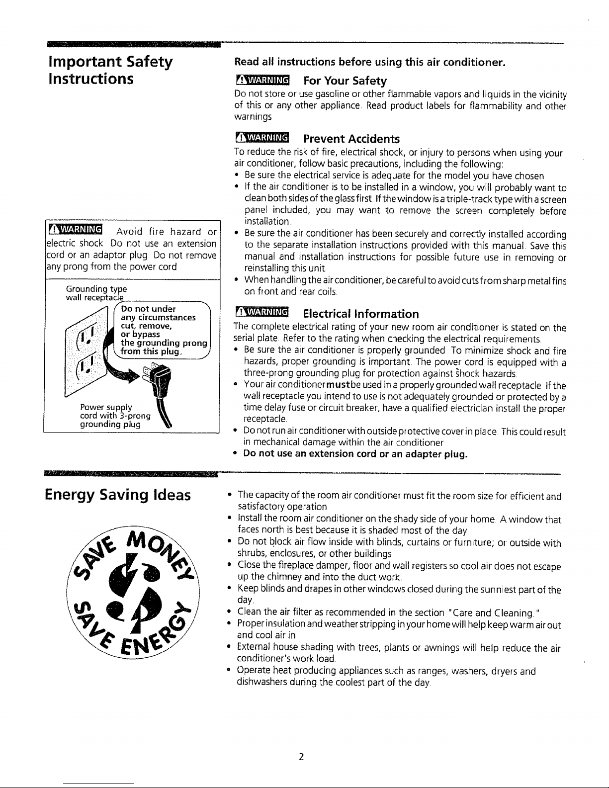
Avoid fire hazard or
electric shock Do not use an extension
cord or an adaptor plug Do not remove
any prong from the power cord
Grounding type
wall receptacle_
SDo not under _"_
Z_: ]1 any circumstances |
-I I _1 cut, remove, I
I\ _ |::__i_ or bypass /
I:: the grounding prongI
Power' supply I!
cord with 3_prong _i,_,
grounding plug I_\
Prevent Accidents
To reduce the risk of fire, electrical shock, or injury to persons when using your
air conditioner, follow basic precautions, including the following:
• Besure the electrical service isadequate for the model you have chosen
• If the air conditioner is to be installed in a window, you will probably want to
cleanboth sidesof the glassfirst Ifthe window isatriple-track type with ascreen
panel included, you may want to remove the screen completely before
installation,
• Besure the air conditioner has been securely and correctly installed according
to the separate installation instructions provided with this manual, Savethis
manual and installation instructions for possible future use in removing or
reinstalling this unit
• When handling the air conditioner, be careful to avoid cuts from sharp metal fins
on front and rearcoils.
Electrical Information
The complete electrical rating of your new room air conditioner is stated on the
serial plate. Refer to the rating when checking the electrical requirements.
• Be sure the air conditioner is properly grounded To minimize shock and fire
hazards, proper grounding is important The power cord is equipped with a
three-prong grounding plug for protection against _hock hazards,
• Your-air conditionermustbe usedin aproperly grounded wall receptacle If the
wall receptacle you intend to use is not adequately grounded or protected by a
time delay fuse or circuit breaker, have a qualified electrician install the proper
receptacle
• Donot run airconditioner with outside protective coverin place. Thiscould result
in mechanical damage within the air conditioner
• Do not use an extension cord or an adapter plug.
_- ,_,,
Energy Saving Ideas
• The capacity of the room air conditioner- must fit the room size for efficient and
satisfactory operation
° Install the room airconditioner on the shady side of your home A window that
faces north is best because it isshaded most of the day
• Do not block air flow inside with blinds, curtains or furniture; or outside with
shrubs, enclosures, or other buildings.
• Close the fireplace damper, floor and wall registers so cool air does not escape
up the chimney and into the duct work.
o Keep blinds and drapes in other windows closed during the sunniest part of the
day.
• Clean the air filter as recommended in the section "Care and Cleaning."
• Proper insulation andweather stripping in your home will help keep warm air out
and cool air in
• External house shading with trees, plants or awnings will help reduce the air
conditioner's work load.
• Operate heat producing appliances such asranges, washers, dryers and
dishwashers during the coolest part of the day
How and Why
Your room air conditioner provides the following functions to make hot
weather living more comfortable:
. Cools and circulates room air
- Lowers humidity by removing excessmoisture
o Filters out summertime dust, dirt, and some airborne impurities
The air conditioner performs these functions by drawing room air through a filter
which traps dust and dirt particles, The air then passesover a cooling coil which
refrigerates the air and removes excessmoisture, The same air isthen returned to
the room-- cooler, drier and cleaner Moisture removed from the room air is
carried to the outside and evaporated.
Your air conditioner is designed to be easyto operate and to provide plenty of
cooling power
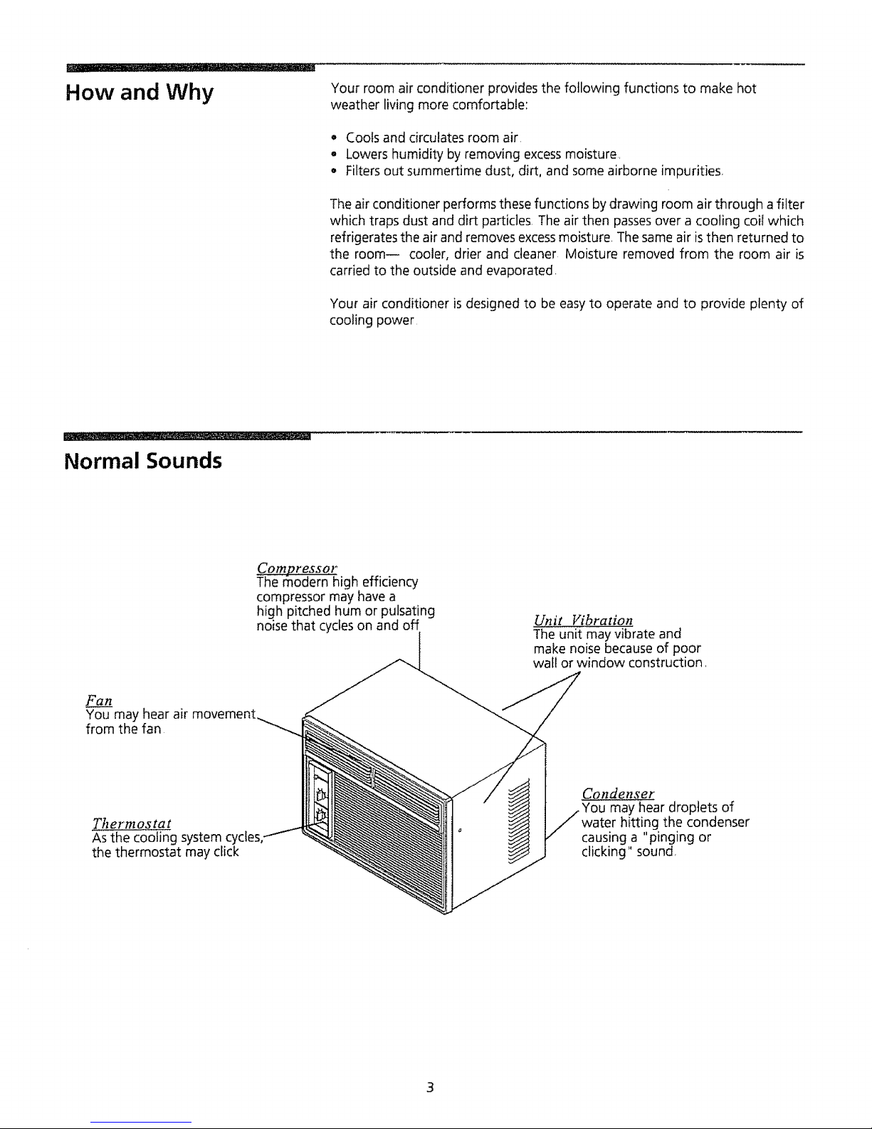
Normal Sounds
Compressor
The r:nodern high efficiency
compressor may have a
high pitched hum or pulsating
noise that cycleson and off
Unit Vibration
The unit may vibrate and
make noise becauseof poor
wall or window construction,
Fan
You may hear air
from the fan
Thermostat
As the cooling system
the thermostat may click
Condenser
may hear droplets of
water hitting the condenser
causing a "pinging or
clicking" sound,
3
I II .j_, ..............................
Front Installation
,,1
L
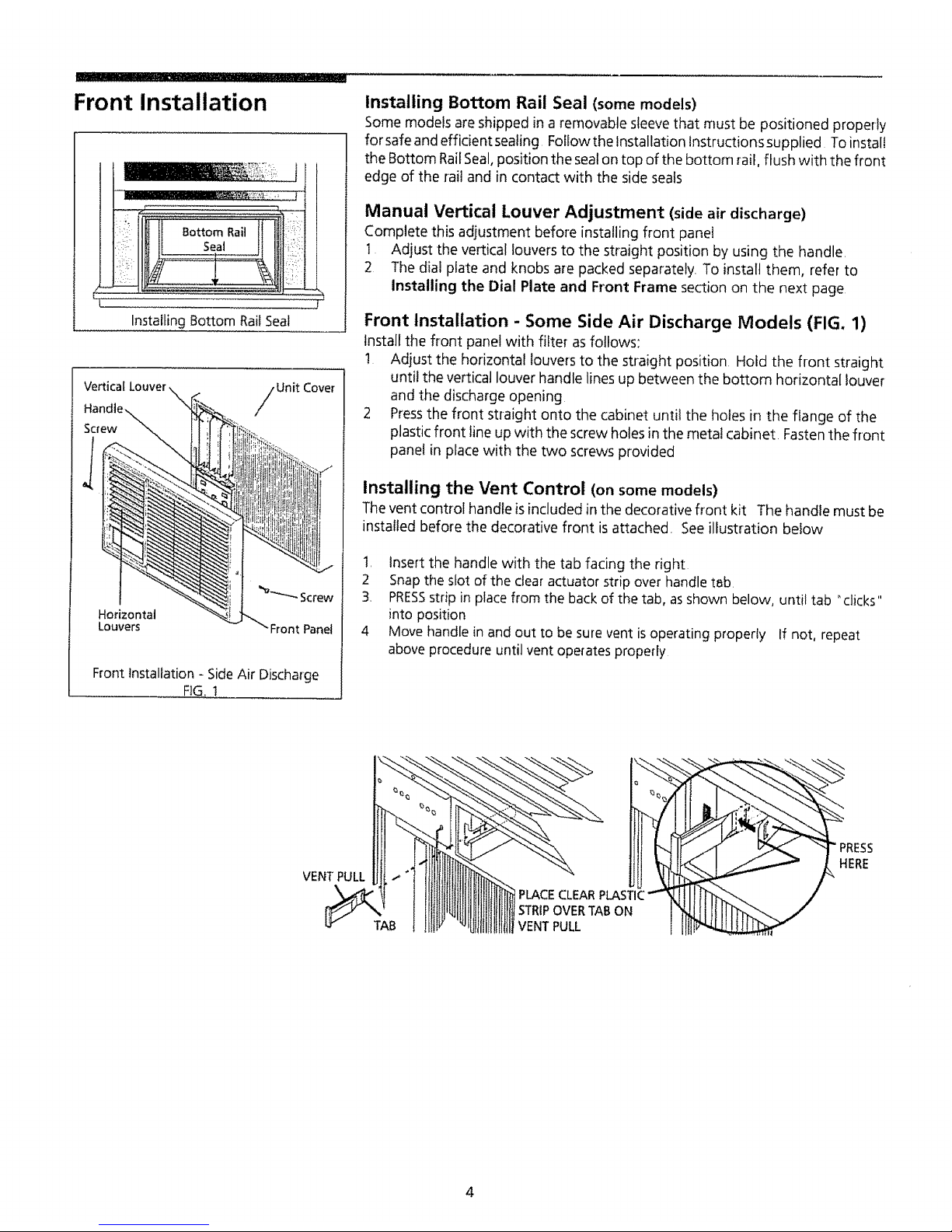
Installing Bottom RailSeal
Vertical
Screw
Unit Cover
Horizontal
Louvers Front Panel
Front Installation - SideAir Discharge
FIG,
Installing Bottom Rail Seal (some models)
Some models are shipped in a removable sleeve that must be positioned properly
forsafeand effidentsealing Followthe Installation Instructionssupplied Toinstall
the Bottom RailSeal,position the seaton top of the bottom rail, flush with the front
edge of the rail and in contact with the side seals
Manual Vertical Louver Adjustment (side air discharge)
Complete this adjustment before installing front panel
1 Adjust the vertical louvers to the straight position by using the handle,
2 The dial plate and knobs are packed separately. To install them, refer to
Installing the Dial Plate and Front Frame section on the next page
Front Installation - Some Side Air Discharge Models (FIG. 1)
Install the front panel with filter asfollows:
t Adjust the horizontal louvers to the straight position Hold the front straight
until the vertical louver handle lines up between the bottom horizontal louver
and the discharge opening
2 Pressthe front straight onto the cabinet until the holes in the flange of the
plastic front line up with the screw holes inthe metal cabinet Fastenthe front
panel in place with the two screws provided
Installing the Vent Control (on some models)
The vent control handle isincluded in the decorative front kit The handle must be
installed before the decorative front is attached. See illustration below
1, Insert the handle with the tab facing the right
2 Snap the slot of the clear actuator strip over handle tsb
3. PRESSstrip in place from the back of the tab, as shown below, until tab "clicks"
into position
4 Move handle in and out to be sure vent is operating properly If not, repeat
above procedure until vent operates properly
VENT' PULL !
PLACE CLEAR
STRIPOVER TAB ON
VENT PULL
RESS
ERE
4
Front Installation
(continued)
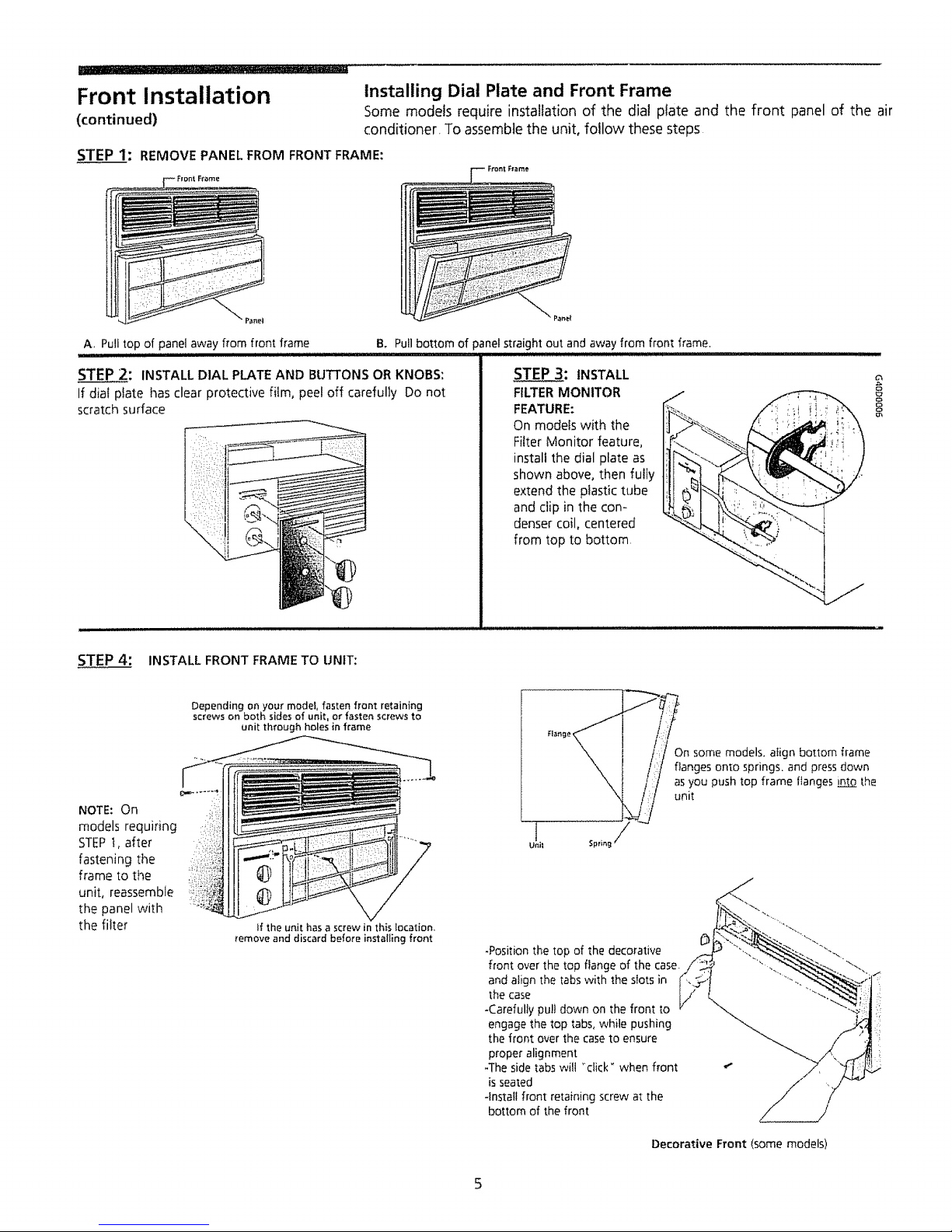
Installing Dial Plate and Front Frame
Some models require installation of the dial plate and the front panel of the air
conditioner. To assemblethe unit, follow these steps
STEP 1: REMOVE PANEL FROM FRONT FRAME:
A, Pull top of panel away from front frame
iiii1,1 i,i1,11ii ....................................................................................................
STEP 2: INSTALL DIAL PLATE AND BUTTONS OR KNOBS:
If dial plate has clear protective film, peel off carefully Do not
scratch surface
B, Pull bottom of panel straight out and away from front frame,
STEP 3: INSTALL
FEATURE: '_
On models with the
Filter Monitor feature° i,_.
install the dial plate as
shown above, then fully
extend the plastic tube
and clip in the con-
denser coil, centered
from top to bottom
%
I
J
J;;
STEP 4: INSTALL FRONT FRAME TO UNIT:
Depending on your model, fasten front retaining
screws on both sides of unit, or fasten screws to
unit through holes in frame
NOTE: On
models requiring
STEP t, after
fastening the
frame to the
unit, reassemble
the panel with
the filter
If the unit has a screw in this location.
_emove and discard before installing front
I /:/ On some models, align bottom frame
_, I // as you push top frame flanges into the
unit
Unil Spring _
-Position the top of the decorative
front over the top flange of the case.
and align the tabs with the slots in
the case
-Carefully pull down on the front to
engage the top tabs, while pushing
the front over the case to ensure
proper alignment
-The side tabs will "dick" when front
is seated
-Install front retaining screw at the
bottom of the front
Decorative Front (some models)
Using the Air Conditioner
NOTE: If the air conditioner is turned off,
wait 3 minutes before restarting This
allows pressure inside the compressor to
equalize Failure to follow these
instructions may cause inefficient
operation.
To reduce the riskof fire, electric shock, or injury to persons, readthe
IMPORTANTSAFETYINSTRUCTIONSbefore operating this appliance
To begin operating the air' conditioner, follow these steps:
t Pluginthe airconditioner (Toprevent electrical hazards, do not useanextension
cord or an adapter plug_)
2 Setthe exhaust vent to the CLOSEDposition
3 Setthe TEMPControl to the coolest setting
4 Setthe fan control at the highest levet
5 Adjust the louversfor comfortable air flow
6 Once the room has cooled, setthe fan to the POWERSAVERFANsetting and/
or adjust the TEMPControl to the setting you find most comfortable
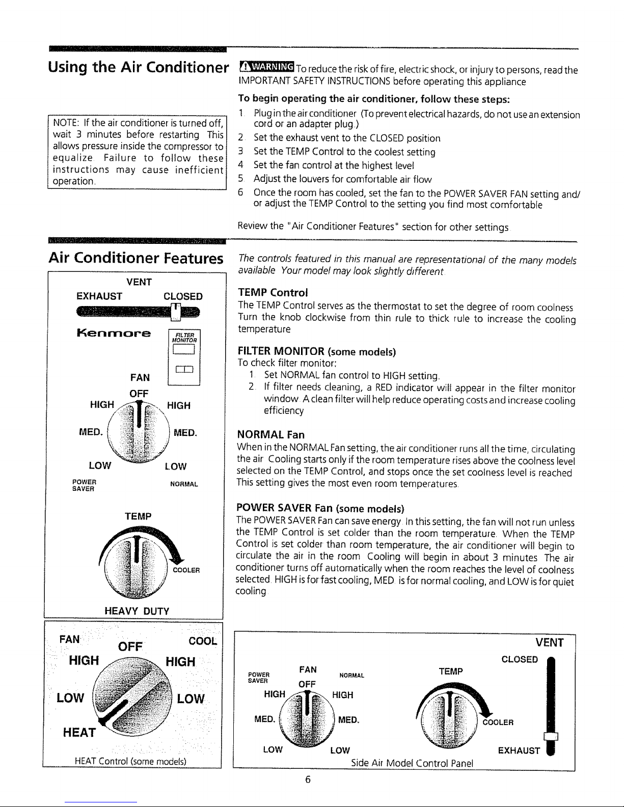
Air Conditioner Features
VENT
EXHAUST CLOSED
Kenmore
FAN
OFF
:.. ,,
LOW LOW
POWER NORMAL
SAVER
TEMP
COOLER
HEAVY DUTY
FAN= OFF cool
::::HIG IGH.
HEATConirol (somemodels)
Reviewthe "Air Conditioner Features" section for other settings
The controls featured in this manual are representational of the many models
available Your model may look shghtty dsfferent
TEMP Control
The TEMPControl serves asthe thermostat to set the degree of room coolness
Turn the knob clockwise from thin rule to thick rule to increase the cooling
temperature
FILTER MONITOR (some models)
To check filter monitor:
t Set NORMAL fan control to HIGH setting,
2. If filter needs cleaning, a REDindicator will appear in the filter monitor
window A clean filter will help reduce operating costsand increase cooling
efficiency
NORMAL Fan
When in the NORMAL Fansetting, the airconditioner runs allthe time, circulating
the air' Cooling starts only if the room temperature risesabove the coolness level
selected on the TEMP Control, and stops once the set coolness level is reached
This setting givesthe most even room temperatures.
POWER SAVER Fan (some models)
The POWERSAVERFancan save energy tn this setting, the fan will not run unless
the TEMP Control is set colder than the room temperature When the TEMP
Control is set colder-than room temperature, the air conditioner will begin to
drculate the air in the room Cooling will begin in about 3 minutes The air
conditioner turns off automatically when the room reaches the level of coolness
selected HIGHisfor fast cooling, MED isfor normal cooling, and LOW isfor quiet
cooling
FAN
POWER NORMAL
SAWR OFF
HIGH HIGH
MED. MED,
TEMP
VENT
CLOSED
COOLER
LOW
LOW
Side Air Model Control Panel
EXHAUST
Air Conditioner Features
(continued)
HEAT (some models)
The HEAT selection provides quiet, efficient circulation of warm air Turn the
selector to the HEATsetting and setthe thermostat to the warmest setting, When
the HEAT setting is selected, the thermostat maintains the temperature by
automatically turning the heater on and off in response to room temperature
Once the room is warm, adjust the thermostat to a cooler setting, The fan runs
continuously to circulate air in the room
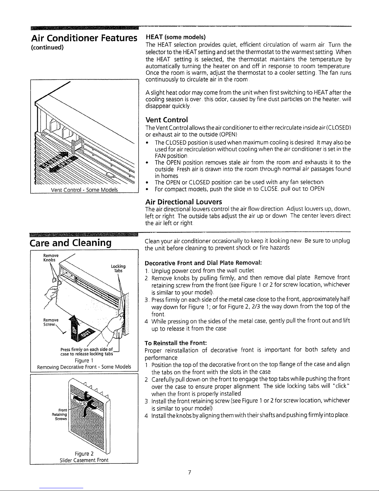
Vent Control - Some Models
A slight heat odor may come from the unit when first switching to HEATafter the
cooling season isover this odor, causedby fine dust particles on the heater, will
disappear quickly
Vent Control
TheVent Control aitowsthe air conditioner to either recircutate inside air(CLOSED)
or exhaust air to the outside (OPEN)
The CLOSEDposition isused when maximum cooling isdesired It may also be
usedfor air recirculation without cooling when the air conditioner isset inthe
FANposition
- The OPENposition removes stale air from the room and exhausts it to the
outside Freshair isdrawn into the room through normal air passagesfound
in homes
• The OPENor CLOSEDposition can be used with any fan selectfon
o For compact models, push the slide In to CLOSE.pull out to OPEN
Care and Cleaning
Air Directional Louvers
The air directional louvers control the air flow direction Adjust louvers up, down,
left or right The outside tabs adjust the air up or down The center leversdirect
the air left or right
Clean your air conditioner occasionally to keep it looking new, Besureto unplug
the unit before cleaning to prevent shock or fire hazards
Locking
Tabs
Press firmly on each side of
case to release locking tabs
Figure1
Removing Decorative Front - Some Models
Fronl
Retaining
Screws
Figure 2
SliderCasement Front
Decorative Front and Dial Plate Removal:
1, Unplug power cord from the wall outlet
2 Remove knobs by pulling firmly, and then remove dial plate Remove front
retaining screw from the front (see Figure 1 or 2 for screw location, whichever
issimilar to your model),
3 Pressfirmly oneach sideof the metal caseclose to the front, approximately half
way down for Figure 1;or for Figure 2, 2/3 the way down from the top of the
front.
4 While pressing on the sidesof the meta! case, gently pull the front out and lift
up to release it from the case
1"oReinstall the Front:
Proper reinstaflation of decorative front is important for both safety and
performance
t Position the top of the decorative front on the top flange of the case and align
the tabs on the front with the slots in the case
2 Carefully pull down on the front to engage the top tabs while pushing the front
over the case to ensure proper alignment The side locking tabs wilt "click"
when the front is properly installed,
3 Install the front retaining screw (see Figure 1 or 2 for screw location, whichever
issimilar to your model)
4 Install the knobs by aligning them with their shafts and pushing firmly into place.
Care and Cleaning
(continued)
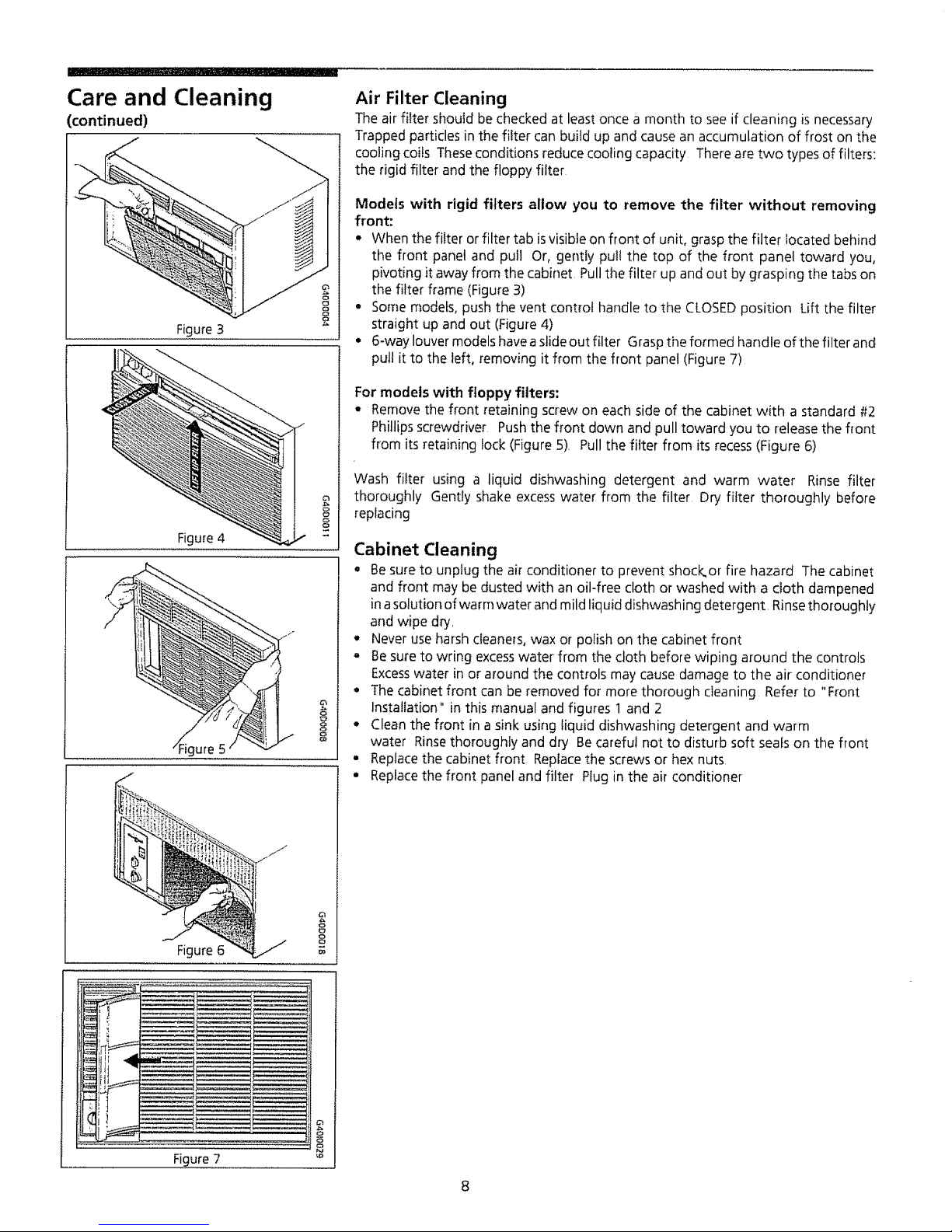
Figure 3
Figure 4
8
8
8
8
o
o
v_
Air Filter Cleaning
The air filter should be checked at least once a month to see if cleaning is necessary
Trapped particles in the filter can build up and cause an accumulation of frost on the
cooling coils These conditions reduce cooling capacity There are two types of filters:
the rigid filter and the floppy filter
Models with rigid filters allow you to remove the filter without removing
front:
* When the filter or filter tab isvisibIe on front of unit, grasp the filter located behind
the front panel and pull Or, gently pult the top of the front panel toward you,
pivoting it away from the cabinet, Pull the filter up and out by grasping the tabs on
the filter frame (Figure 3)
o Some models, push the vent control handle to the CLOSED position Lift the filter
straight up and out (Figure 4)
. 6-way louver models have a slide out filter Grasp the formed handle of the filter and
pull it to the left, removing it from the front panel (Figure 7)
For models with floppy filters:
- Remove the front retaining screw on each side of the cabinet with a standard #2
Phillips screwdriver Push the front down and pull toward you to release the front
from its retaining lock (Figure 5), Pull the filter from its recess (Figure 6)
Wash filter using a liquid dishwashing detergent and warm water Rinse filter
thoroughly Gently shake excesswater from the filter Dry filter thoroughly before
replacing
Cabinet Cleaning
Q Be sure to unplug the air conditioner to prevent shock, or fire hazard The cabinet
and front may be dusted with an oil-free cloth or washed with a cloth dampened
in asolution of warm water and mild liquid dishwashing detergent Rinse thoroughly
and wipe dry,
- Never use harsh cleaners, wax or polish on the cabinet front
° Be sure to wring excess water from the cloth before wiping around the controls
Excesswater in or around the controls may cause damage to the air conditioner
• The cabinet front can be removed for more thorough cleaning Refer to "Front
Installation" in this manual and figures 1 and 2
• Clean the front in a sink using liquid dishwashing detergent and warm
water Rinse thoroughly and dry Be careful not to disturb soft seals on the front
• Replace the cabinet front Replace the screws or hex nuts
• Replace the front panel and filter Plug in the air conditioner
 Loading...