

Sears GT 16 Owners Mnaual
I Sears I
OWNERS
MANUAL
46
',
DOZER
MODEL
917.
USED
MECHANI
MODEL NO.
917.254030
917 .
254020
254040
Read
Safe Operation
and
NO.
WITH
SM
Caution:
Rules
Instructions
Carefully
LIFT
OR
for
46
INCH DOZER
AND
Ll
FT MECHANISMS
i
. '
Assembly
Installation
Operation
Repair
--------------------------------------
Sea
rs, Roe
buck
and Co., Chicago, Ill. 60684, U.S.A.
Parts
--~
~
ASSEMBLY INSTRUC
TIO
NS
...........
TABLE OF
. .
....
1
CONTENTS
MAINTENANCE
INSTRUCTIONS
..............
9
ADJUSTMENT
OPERATION INSTRUCTIONS . .
IN
STRUCTIONS . .
...........
...........
FULL ONE
For
one year
ment, at
If the
tractor
of
date
Warranty service
Center
This
warranty
1.
Know
the
OWNER'S
2.
Do
not
adults
3.
Do
tance away.
4.
Always
clothing
5.
Keep
area bei
6.
Do
not
7.
Always get
hand side.
Clear the
8.
and
9. Disengage all
fore
allow childr
to
operate
not
carry passengers. Keep children and pets a safe dis·
wear substantial footwear.
tha t could get caught
your
ng
cut.
not
attempt
in drivers
work
thrown.
attempt
10. Disengage power
fore leaving the operator's
11
. Disengage
sp
ark plug
ing
12. Disengage
in
use.
an
adjustm
pow
power
from
date
no charge
purchase.
throughout
controls and
MANUAL.
eyes and
Don't
sea
on
attachment
ing
er to mower, stop the
wire(s)
ent
.
attachment
is
available at
the
United
gives
you
how
en
to
it
to
t.
or
area
to
or
to
operate the vehicl
without prop
mind
on
let
other
operate
off
your
of
objects
clutches and
start the engine.
to
att
achments and stop the engine be·
positio
from
spark plug(s) before cleaning, mak·
repairs.
attachmen
of
purchase,
is
used
States.
specific legal rights, and
RULES
to
stop
er
Do
in
moving parts.
your
int
erests distract
your
tractor
which
n.
ts
when transporting
Sears
for comme
your
home, at
FOR
quickly.
e.
instruction
not
tractor,
tractor
from the operat ors l
shift into neutral be·
engine and disconnect
Do
.
wear loose fi
mower
or
mow
might
be
13. Take all possible precautions when leaving the vehicle un·
attended, such
the attachments, s
brake, stopping the engine, and removing the key.
14.
Do
not
hill.
15
15.
Redu
vent
when changing
16. Do
gear
and
to
stop
Mow
°); never
ce
speed
tipping
not
shift
low
shiftin
slow.
17. Never m
sure
or
at
18. Stay alert fr •
19
.
Do
not
ways.
20. Ex er
in
deliberat
object
21. Never
22
. Never place hands
(discharge chut
mower
d~.
cise
order
ely
.
sh
ift
are running.
as
disengaging the power·take·o
hifting
or
start suddenly wh
up
and
down
ac
ross
on
or
loss
direction
gears
enough
g qears.
ow
wet
"d
::
• ·
•• ott?s in the terrain and
J O close
·
"'Pc...
I care when
to .'·"'vent
run
tra
gea
rs
until
e)
the face
the
face.
slopes and make turns gradually
of
control.
while going up
to
negotiate the slope
To
reduce
or
slippery grass,
whic
h could cause a skid.
to
the blad
ctor
or
tractor
or
feet
or
near any moving parts
Always
into
neutral, sett ing the parking
en
going
of
slopes
on
under
Exercise extreme caution
slopes.
or
speed, move t
creeks, ditches and
mowing
es
from
mow
er
into
com
es
the mower,
keep clear
uphill
(not greater than
down
slopes. Choose a
without
when traction
other
hidden hazards.
around fixed objects
striking them. Never
or over any foreign
to a stop.
in
while
of
d1scharge
hrottle lever
the
. . 7 REPAIR PARTS
. . . 9
WARRAN
YEAR
will
repair any defect in material
rcial
or
rental purposes, this
no
charge, by
you
may also have
SEARS ROEBUCK
Sears
BSC
Chicago, II.
SAFE
READ
THE
not
allow
tting
and the
you.
er when
eft
picked
ff,
public
up
or
not
lowering
or
down·
to
pre·
stopping
is
un·
high·
deflector
tractor
chute.
or
TY
WARRANTY
simply
AN::>
Tower
41
·3
60684
OPERATION
Use
23.
a. Use
b.
c.
d.
24. Watch
25. When
material toward bystanders
hicle
26. Handle
a. Use approved
b. Never remove the cap
c.
27. Keep the vehicle and attachments
dition,
28. Keep
ment
29. Never store the equipment
a building where fumes may reach
Allo
30.
To
or
31. Except
cleaner
moved. Removal
DO
32.
PER
or
ically and replace
33. The vehicle and attachments should
ed
age
equipment.
34
. Do
the eng
35. When using the
a.
b. Never make a
c. Shut the engine
d.
36. Check the
r
Do
37.
catcher,
pl
...
.......
or
workmansh
wa1
ranty applies
contactmg
oth
er
ligh
CO
care when pull i
onl
Limit
Do
not
Use
counterweight
this owner's manual.
out
usmg any attachments, never
whil
gaso
a running
Wipe
Open doors
fumes are dangerous.
and keep safety devices in place.
all nuts,
is
in safe
w the engine
reduce fire hazard, keep the engine free
excessive
or
NOT
WITH
spark arresters could create a fire hazard. Inspect period-
for
damage
should
not
ine.
Mow
only
is
runnmg
unclogging chute.
Check the blade
frequent
ation. Replace
not
operate
on
ace.
your
nearest
ts
whi
ch vary from state
y approved drawbar
loads
turn
for
e in operation.
line
up
spilled gasoline.
grease.
for
adjustment; DO
cover
OPERATE
THE
be
change th e engine governor settings
in
if
mtervals.
grass
mowers
ng
to
those
sharply. Use care when backing.
or
traffic
when crossing
with
care·
gaso
lin
or
hot
engine,
if
the engine
bolts
and screws tig
wor
king
to
cool before storing
directly
of
such part could create a fire
WITHOUT A MUFFLER
EXHAUST
if
necessarv.
after
stri king a foreign object, and the dam-
repaired before restarti
ve
hicle
dayli
ght
cutting
the
operator
off
when removing the
mounting
catcher
with
new
the
Mower
so
equipped,
.
....
. .
..........
ip
in
th1s
tractor
attach·
for
only
thirty
days from
Sea1
s store
or
Service
to
state.
loads
or
usi
ng
hitch points .
you
can safely
wheel weights when suggested
nor
allow
it
is
e containers.
condit
bags
highly
of
the fuel
or
fill
is
run
Do
not
ion.
with
gasoline
NOT
over carburetor air intake
SYSTEM. Dam
with mower
or
in good
height adjustment while the engine
must
bolts
frequentl y
bags for safe
without
heavy equi pment.
control.
or
near roadways.
direct
discharge
anyone near the ve·
flammable.
tank
or
the
in
run
in
ht
an
be
artificial light.
dismount
for
or
the
add gasoline
fuel tank indoors.
the
garage
the
engine
good operating con·
to
be
sure the equip·
in
the tank inside
open flarne
in
any enclosure.
of
operate Engine
aged
stopped and inspect-
ng
and operating the
or
, proceed
to
do
grass
proper tightness at
for
wear or deterio-
ty
protection.
either the
def
lector shield
· exhaust
indoo
or
grass,
haza
OR TAM·
muff
overspeed
as
follows:
so.
catcher or
entire
10
in
of
to
rs.
spark.
leav
es
if
air
is
re·
rd.
lers
gras
in
s
To
assemble
9/16"
your
Dozer
you
will
Wrench Hammer
3/4" Wrench Screwdriver
11/16" Wrench
15/
need:
16"
Wrench
PREPARATION
Remove
mounted
Your
ing
tents
YOU MUST
OR
mower
to
shipment consists
the
Dozer and the
of
both
or
your
tractor.
cartons and
any
HAVE
25404) SUITED TO YOUR TRACTOR
FOR
other
of
two
other a lift
cut
THE
cartons. One
shipping wires.
LIFT
ASSEMBLY
attachment
Mechanism. Remove con-
MECHANISM (25403
TACH DOZER (25402).
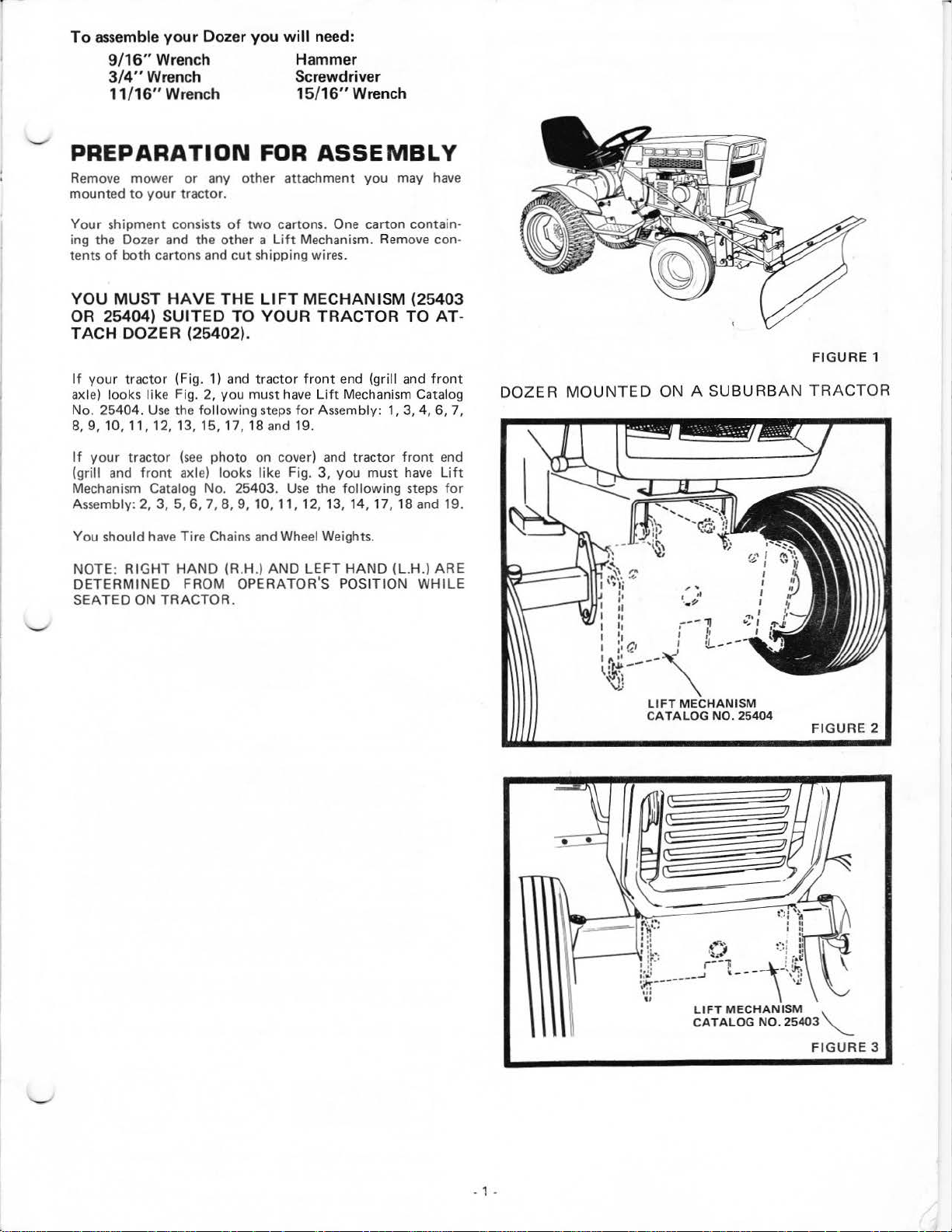
If
your
tractor
axle)
looks
No. 25404.
8,
9,
10, 11, 12, 13, 15, 17,
If
your
tractor
(grill and
Mechanism Catalog No. 25403.
Assembly: 2,
You
should have
NOTE:
DETERMINED
SEATED
RIGHT
(Fig. 1) and
like Fig. 2,
Use
the following
(see photo
front
axle) looks
3,
5, 6, 7,
Tire
HAND
ON
TRACTOR.
tractor
you
must
18
on
8,
9, 10, 11, 12, 13, 14, 1
Chains and Wheel Weights.
(R.H.)
FROM
OPERATOR'S
have
steps
for
and 19.
cover) and
like
Fig.
Use
AND
front
LEFT
Lift
Assembly: 1,
3,
the
you
may have
carton
contain
TO AT·
end (grill and
Mechanism Catalog
tractor
you
must
follow
ing steps
7,
HAND
POSITION
front
3,
4, 6, 7,
front
end
have
Lift
18 and 19.
(L.H.)
ARE
WHILE
for
·
DOZER
MOUNTED
I
I
I
I II I
I
11\::~
~:~f--
II
lo
Ia
'
ON A
~,
--\-
'\J]
LIFT
CA
TALOG
SUBURBAN
, .
I
•I
·-~
;--11
f1
I
•f
---
MECHANISM
NO.
25404
"'
..,,,
...
FIGURE
1
TRACTOR
I
I
FIGURE
2
. 1 .
ASSEMBLY
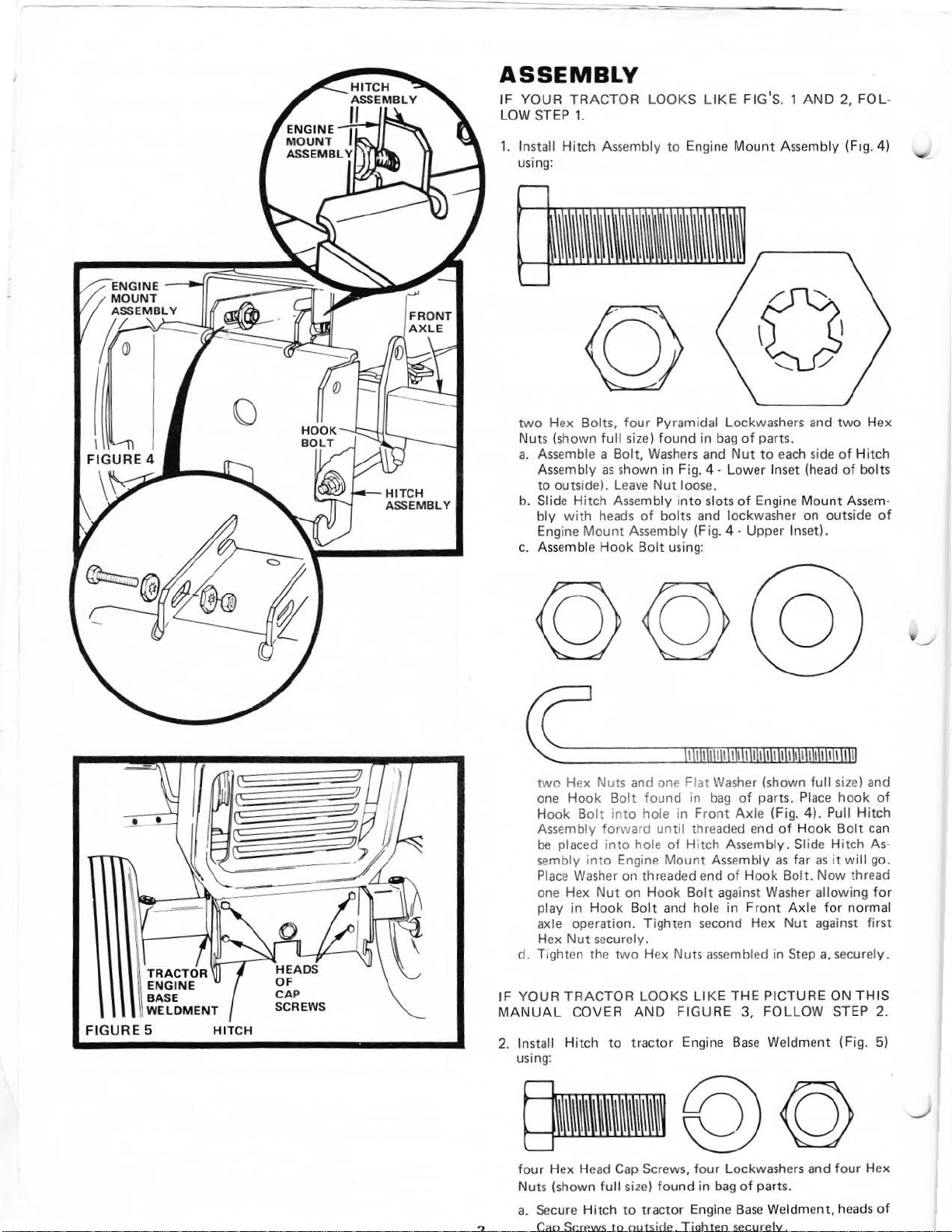
IF
YOUR
LOW STEP
TRACTOR
1.
LOOKS
LIKE
FIG'S
. 1
AND
2,
FOL
·
1. Install
using:
two
Hex Bolts,
Nuts (shown
a.
Asse
Assembly
to
b. Slide
bly
Engine
c. Assemble
Hitch
mble a
outside).
Hitch
with
heads
Mount
Assembly
full
Bolt,
as
shown
Leave
Assembly
Hook
to
Engine
four Pyramidal Lockwashers and
size)
found
Washers
in
Fig. 4 · Lower Ins
Nut loos
into
of
bolts and lockwasher on outside
Assembly
Bolt
using:
in
bag
and
e.
slots
(Fig. 4
Mount
of
parts.
Nut
of
Engine
·Upper
to
Assembly
each side
et
(head
Mount
Inset).
(F1g.
two
of
of
Ass
4)
Hex
Hitch
bolts
em·
of
FIGURE
5
HIT
CH
two
Hex Nuts and one
one Hook B
Hook Bolt
Asse
mbly
be
placed into hole
sembly
Place
one Hex
pl
axle operation. Tighten second Hex
Hex
d.
T;gh ten the
IF
YOUR
MANUAL
2. Install Hitch
using:
four
Nut
a. Secure Hitch
? . Cap Screws
int
Washer on threaded end
ay
s (shown
Nut
in
Hook
Nut
securely.
TRACTOR
COVER
Hex Head
olt found in
into
hole
for
ward
until
of
o Engi
ne
Mount Assembly
on
Hook
Bolt and hole
two
Hex Nuts assembled
LOOKS
AND
to
tractor Engine
Cap
Screws,
full
size)
found
to
tractor
to
out
side. Tighten securely.
Flat
Washer (shown
bag
of
parts.
in Front
Hitch Assembly. Slide Hitch As·
Bolt
FIGURE
Axl
e (Fig. 4). Pull Hitch
threaded end
of Hook
against Washer allowing
in
Front Axle
LIKE
THE
3,
Base
four Lockw
in bag
of
parts.
Engine
Base
full
size) and
Place
hook
of
Hook
Bolt
as far
as
it
will
Bolt.
Now
thread
for
normal
Nut
against first
in
Step
a.
securely.
PICTURE
FOLLOW
Weldment (Fig. 5)
ashers
Weldme
and
nt,
ON
THIS
STEP 2.
four
heads
of
can
go.
for
Hex
of
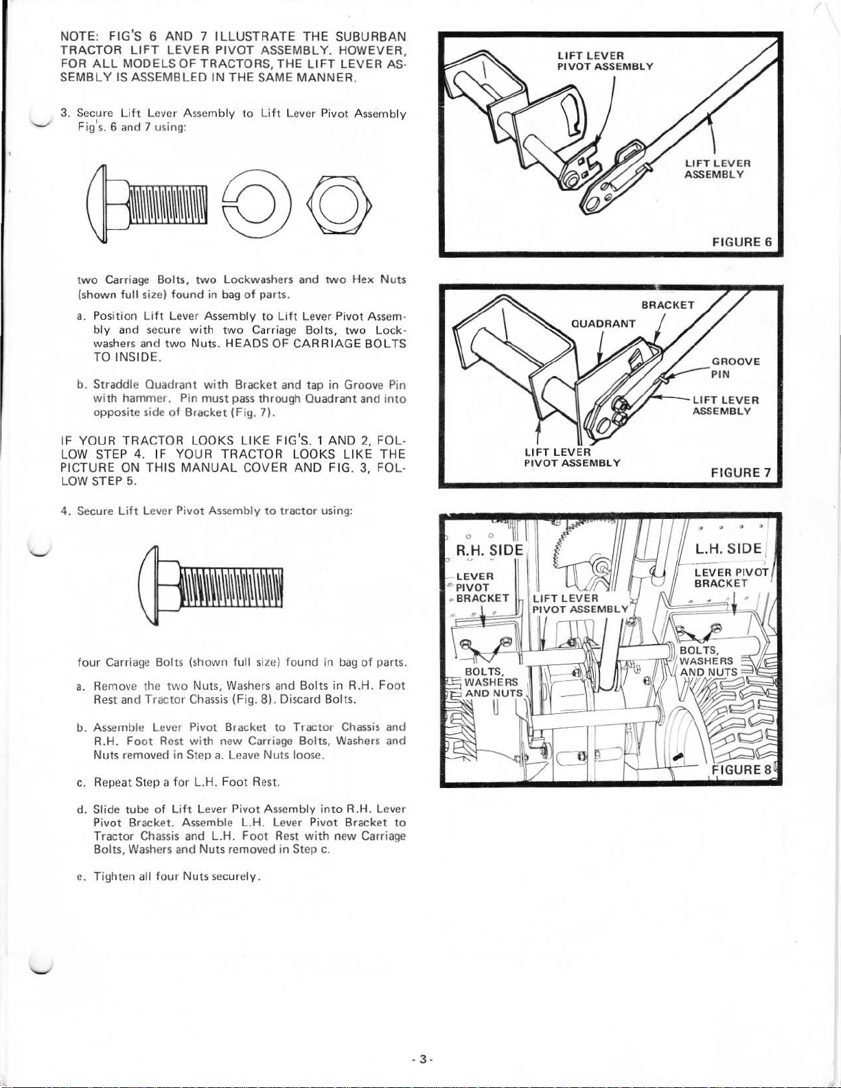
NOTE: FIG'S 6
TRACTOR
FOR
SEMBL Y IS
3. Secure
.._,
Fig'
two
(shown
a.
AND 7 ILLUSTRATE
LIFT
LEVER
ALL
MODELS OF TRACTORS,
ASSEMBLED
Lift
s.
6 and 7 using:
Carriage Bolts,
Lever A
full
siz
Position
bly
Lift
and secure
washers and
sse
two
e) found in
Lever Assembly
with
two
Nuts.
TO INSIDE.
PIVOT
ASSEMBLY. HOWEVER,
THE
IN
THE
SAME
mbly
to
Lift
Lockwashers and
bag
of
parts.
to
Lift
two
Carri
HEAD
age
S OF
THE
SUB
URBAN
LIFT
LEVER AS·
MANNER
.
Lever Pivot Assembly
two
Hex Nuts
Leve
r Pivot
Ass
em·
Bolts,
two
CARRIAGE
Lock·
BOLTS
FIGURE 6
b. Straddle Quadrant
with
hammer. Pin must
opposite side
IF YOUR
LOW STEP
TRACTOR
4.
IF
PICTURE ON THIS
LOW STEP
4.
Secure
four
a. Remove the
5.
Lift
Carriage Bol
Rest and
Lever Pivot Assembly
two
Tractor
b. Assemble Lever
R.H.
Foot
Rest
Nuts removed in
c.
Repeat Step a
of
Bracket (F i
LOOKS
YOUR
MANUAL
ts
(shown
Nuts,
Chassis
P
ivot
with
Step
for
L.H.
with
Bracket and tap in Groove Pin
pass
through Quadrant and into
g.
7).
LIK
E FIG'S. 1
AND
TRACTOR LOOKS
COVER
full
Washers
AND
FIG
to
tractor
siz
e) found
using:
in
and Bolts in R.H.
(Fig. 8). Discard Bolts.
Bracket
to
Tractor
new Carriage Bolts,
a.
Leave Nuts
Foot
loose.
Rest.
2, FOL-
LIKE
. 3,
bag
of
Chassis
Washers
THE
FOL
parts.
Foot
and
and
-
--LIFT
LIFT
LEVER
PIVOT
·
ASSEMBLY
L
EVE
ASSEMBLY
FIGURE
R
7
d.
Slide tu
P
Tractor
Bolts,
e. Tighten all
ivot
be
Bracke
Chassis
Wash
of
Lift
Lever P
t.
Assemble L.H. Lever Pivot Brack
and
ers
and Nuts removed in Step
four
Nuts securely.
L.H.
ivot
Foot
Assembly
Rest
int
o R.H. Lever
with
new Carriage
c.
et
to
.
3.
 Loading...