

Page 1
,^
ti
=t'
SEARS
DEPT.731A
TECHNICAL
FLASH
DISTRICT
MANAGER
CENTRAL
MANAGER
BRANCH
MANAGER
CALL
CENTRE
MANAGER
PARTS
MANAGER
T. F. 46-93
ocToBER
2001
L.DIVELL
-
DBPARTMBNT
731A
DTVISION
46
SOTJRCE
C978 G.E.
ERVICE
INFORMATIO
Arctica/Prof
i le/G
E Side-by-Side
Refrigerators
with Electronic
Touch
Controls
MODEL
SERIES:
PSS
and GSS
23, 25,
27
and
29 inch
NOTE:
n
FOR PARTS ORDERING
USE
DIVISION 46
SOURCE
C978
Page 2
IMPORTANT
SAFETY
NONCE
The information in
this
service
guide
is intended
for
use by
individuals
possessing
adequate
backgrounds
of electrical,
electronic,
and
mechanical
experience.
Any attempt to
repair
a
major appliance
may result
in
personal
injury
and
property
damage. The
manufacturer
or seller cannot
be responsible
br the
interpretation
of this
information,
nor
can
it
assurne
any liabilig
in
connection witr
its use.
WARNING
To
avoid
personal
iniury
disconnest
power
bebre
servicing
this
product.
lf
electrical
power
is required
for
diagnosis
or test
purposes,
disconnec.t the
power
immediately
after
performing
the
necessary
checks.
RECONNECT
ALL GROUNDING
DEVICES
lf
grounding
wires, screws, sffiaps,
clips, nuts,
or washers
used
to
complete
a
path
to
ground
are removed
for
seMce,
they
must
be retumed
to
their original
position
and
properly
fastened.
GE Consumer
Hone
Serulbes
Training
Technial
Servie Guide
Copyright@ 2001
All rights reserved.
This service
guide
may not
be reproduced
in whole or in
part
in
any
form without written
permission
from the
Genenl Electric
Comparry.
(-
Page 3

Table of Gontents
\J
o
63
Page 4
2001 Energy
SxS models
are
being
introduced
in
response
to the
requirement
for
more
energy-
efficient
refrigerators
by
mid
year
2001,
along
with
feature
and
operation
enhancements.
The
primary
differences
in
this refrigeration
system
are
the
adaptive
defrost
system
(see
Pub #
gt-9062),
control
board,
software,
and control
systems
that
operate
independently
in fresh
food
and
freezer
sections.
The
new high-efficiency
control
system
has
the
ability to
cycle components
and
adjust
fan
speeds
as required
to
maintain
temperature-
setting
ranges
in
fresh food
and
treezer
sections.
Feedback
systems
are digital
inputs
and
relay
ouputs.
Sensors
(thermistors)
are used
to
measure
temperature
with
communications
to
a
main
PC
board,
which controls
the unit
components.
The
Refrigerator
has
touchpad
controls
to
provide
inputs
to
a microprocessor.
The
fresh
food
and
treezer
controls
are
temperature
sepoint
type
and
have
settings
of
G9
with
9
being the
coldest
temperature
possible.The
new
NO
CLEAN
condenser
is
serviceable from
the
rear
and
is
designed
to
prevent
the customer
from
having
to
clean
the
condenser
in normal
usage
conditions.
Sealed
system
operation
and
compressor
are
functionally
the
same
as
previous
models,
with
some
minor
changes.
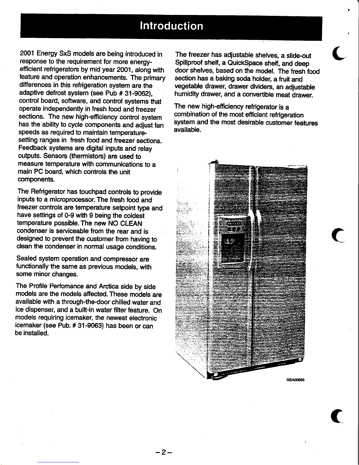
The
Profile
Perfomance
and
Arctica
side
by
side
models
are the
models
affected.
These
models
are
available
with
a through-thedoor
chilled
water
and
ice
dispenser,
and a buift-in water
filter
feature.
On
models
requiring
icemaker,
the
newest
electronic
icemaker (see
Pub. #
31-9063) has
been
or can
be installed.
The
freezer
has
adjustable
shelves,
a slide.out
Spillproof
shelf,
a
QuickSpace
shelf,
and
deep
door shelves,
based on
the
model.
The
fresh
food
sestion
has
a baking
soda
holder,
a
fruit
and
vegetable
drawer,
drawer
dividers,
an
adjustable
humidity
drawer,
and
a convertible
meat
drawer.
The new high-efficiency
refrigerator
is
a
combination
of the
most
efficient
refrigeration
system
and the most
desirable
customer
features
available.
-2-
Page 5
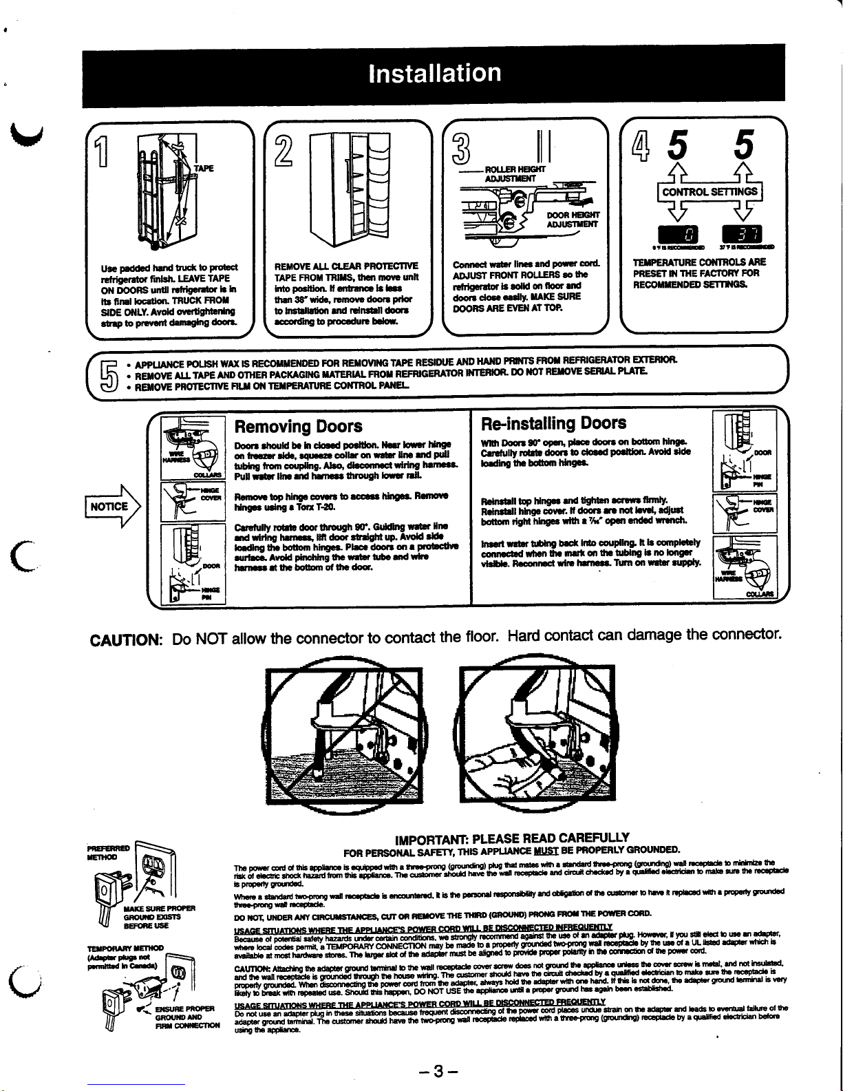
RETIOVE
AIJ. CT.EAB
PFOTEfiIVE
TAPE
FROil TRllls,hc||
mfl!
unlt
hopcnolt.
f ailtmc.bL.a
rhJ|3f
wid., rlmout
rfooc
ptbi
to hfilEdo,r
Jd
rdnsrll dodt
rcconthg
to
ploccdut!
bdo|.
TEXPERATURE @I{IROIS
ARE
PRESET N I}IE
FASTOFI
FOR
REOOTTETDED
SETTIIGS
L
ill
FOU.EN
HEGFT
AD'ITsTE{T
CoilEcl
rsEr
lltElnd
Poutrcord
AqTUST
FROIIT
BOLTERS
3o
$e
rutrigeretu
le rlld
m
fioorra
dooildec.dlY.
SAXESUFE
DOORS
ARE
EVEI{ AT
TOP.
1
u3G
p€dd.d
hJld
tud(
fo
Prot?ct
rGfrtsprator
finteh"
IEIYE
TAPE
ON
oOORS
ulill
rrfrignrelor
b h
llr linel
locdron.
TRUCK
FFOI
gDE
OilLY.
Avold
ot,ltdg|hbdtl3
.urpto
pr€atnt d.t||.g[ng
dootr
rF
.
APPTJA'IGE
PIoIJS}I
wAx IS
RECOTilEIIDED
FOR
RETOYII{G TAPE
RSSIDIE
AT{D
HAND
PRfffS
FROI
REIR]CERAIOR
EXTEHON.
Ui\
.;EirovElrrepernoonrenpAcKAGll{crlrERlAtFRorREFRrcERAroRll{TERloRDollorRErovESEHALPLATE
C-/
.
aqOve
PFOrEsrm
HIJ
0t{
TilPERAnnE
CONTRoL
P ilEL
Re-installing
Doors
Wnh
Ddr
S
o9.tt,
dre
tloo?. on
betn hhg!'
C.rttully
rctrb
d@tt
b do..d
pclti(tn"
Avoid i&
lodlngt|f,benhhgL.
F.ln$rll
bP
hltE
. .nd
tgftbn
srm
fmly.
Rdndrlt
hln$
covtt
It tloq3
f|
nol Lvtl, ldilaf
botlom
tigm
hhgGs
rlll r
7f,' oFl
qldd
uillCl.
ln
.d
rltlr talt|g
b.d(
ltio coudlng lt
Ir
cmplctrly
connoadficn
thr nrtton
tlr tDlng
b no bngpt
vb5aa. R.cootEtwl]t
lrnaaa.I||'|l
olt
wtE tupPly.
Removing
Doors
Door|.hould
b. h dot
d
p6ltlon.
]bt lou.t
lt&|gp
qr
frEr dd., t|lrrc
cdk
on
rlbt Un
r|d
Polt
trbhg
fton coup[ng.
Abo'.tbcontLct
rlrlng
hl||..r
Pu[ '|F
llna md
hlac$ tfuottgh
lorrr nlt
Rqnovr
top hlttgt coF'l
to scc..a
l*|grj
F.r|oUt
Hngr. lCng
rlcrT{0.
Crrdully
rdil! tfoorfttot8h
3C.
Gufhg
r|llrlfir
nd
;irlrU lurnc* m.bo?
ldgftl
W.
Atold
3i.l.
-
ld|f,ng O|. botorn
hirEGa.
Pbca.looc
ofi a
Ptollcltv!
an'f€. ArroS
phchhg
!r
r|t r tfr. f|d
rttt
tura|.
tt 0E
botbm of 0|.
do6.
CAUTION:
Do
NOT
ailow
the connector
to contact
the
floor.
Hard
contact
can
damage
the connector.
ffim
IEIFONABYIEfiOO
(Adrprl[Nlnc
Frrndhffi)
IMPOFTANT:
PLEASE
READ
CAREFULLY
FOR PERSOIIAL
516NY
g$
APFUAilCEIIISI
BE PROPERLY
GROUNDED'
the
Fomr
@r,
.a
thb
appfi.r
b .$bp.d
rfi I tn
.Fso
Gmntng)llug
td Jtdc
$h ! drn
htd lrlflltrg
Gtgftdfto)
m!
tE
Pldl
b n*irilt
lhc
,i*
ot
.t
Gric
!ho.k
tiazrd r- 113 .iffi]ii-i3,ii}
:fria
rni'rip-ml
ocrpoar
lrro doit
dr.dad
by i
q!tr
d ddiiln
lo trta 3n
lh'
E€pE
ir
propody
!|grrxt
a
rin[r ! srerrrsrd
trpmg
tEI rlc.pEdr b
m,ni.rtd,
r b
lhc
Flctd
rsB.tTdy.nd
oDagdon
ol t! ollom.r
to
hm n r.P6
ul'| r
pcFdy
rrqt|dd
tE
ft!.fg
rd nca06d..
DOilgT.UilOEnAt|tf
c|nctffif
llccs,cuTonBETVETHEflInD(GnouD)PnoiacFMnGPOITEFOOnD'
rrsAGE smrrfloils
wHEnE
rHE
lPP|xr|cErs
FglvEn
conD
x4+P!]06coinEcffiD
rfif,qguErtra.Y
Bacals
of
po!3rilu
etsty
rrarus rnoer]m-conotc,
m *onOv
mrmmo
agsi6qt
ut
of ]raah9bcprro-
Hffi. !w sil €Lctb
B D
dhprtr'
yr€ctocd@(bspom{,lTEtpcrFAF.
@NNECTIONrrraytcnader.rprcffifinbcuro+onop4ircda&Uytrcu-otaut-tiur@awtruti
iyrnruearndh.rdm.l",*.rn"iidiiiiJfr"-;d;&t;b";l6ri'tiilrpwriranvhfT
of,itcibnc't!Pont€od
caunoil:AltrrhholhaadapLrgrurdunrinerbthet,|dttoc4tadaco\,arrctwdcnotgufdttt|peLtEultsth3ffis€wbm'bl'JdnotlB'8
4
lrd nr
r.r lgc.Fiad€
ts
g".d"d
!d;'ii;;;"ffi;.-1#
c$sromt
dro,Jd
mn
rr &an
areorJ by. gglfi.d
d.6icitn D
mtla ,n
lh. Gc.gtacr
b
pteervgdrd.d
rna ccom*nfddi;
dnrocrun-tE
aqqebr
dqs-trolctte
ro*ttdth
drhdrd.
tit& b
mrdm,lho
arhprsg[urd
bn*ts|bnry
[i& ri riJr
kr roparC
,rs". Srr.ni-ffffi',
OO-NOTGE]|
qttrtr
urr
.
pFD.r gistd ]E
agth
ban
6ffi.
usecs
snumons
wnene
nre epn l^nces
Pq|En
colD
lu!!+EDFFdilRr:
T?Sry_.f-Y. - -
DonotHa.rt
pilrpl6inte@AGpurm-ptesunlrrfah6ltr.dobrtndLa&ba[rtnlhilwd$a
adaprergro'rd
bmrn1.rn"
or.1*rfiiiliffiffi;&;6;i
Hrir*,-'+Ircd*,thitncpmg
(gdndtd Eog*c ov
aqnrfi.d d€clidm
bsH€
|AhgtF
applJr..
@
r{ erwn:rnorcn
GROI,ID
AI{D
FilOomGcnoil
-3-
Page 6
DISCONNECT
POWER CORD
BEFORE
SERVICING
IMPORTANT-RECONNECT ALL
GROUNDING DEVICES
All
parts
of this
appliance
capable
of conducting
electrical
current are
grounded.
lf
grounding
wires,
screvys,
straps,
clips,
nuts
or washers used to complete
a
path
to
ground
are
removed
for service, they must
be returned
to
their original
position
and
properly
fastened.
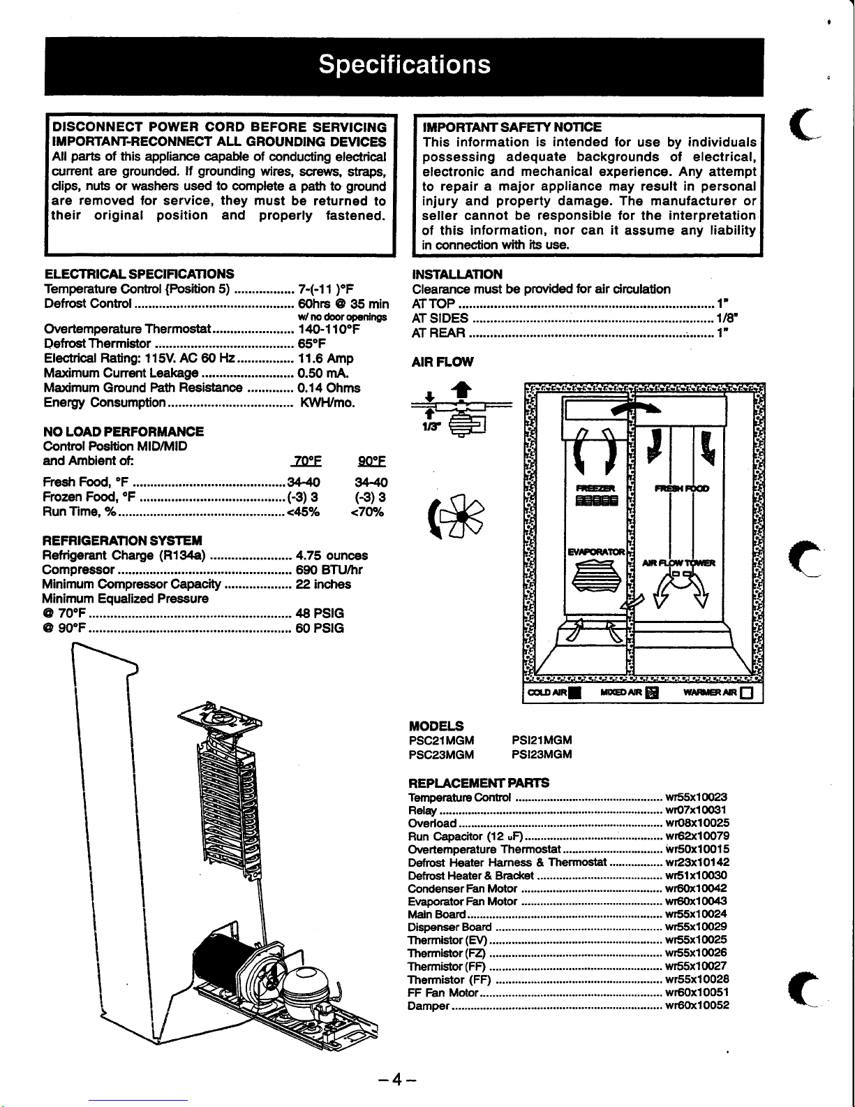
ELECTRICAL
SPECIF|CANONS
Temperature
Control
{Position
5) .................
7-(-11
fF
Defrost Control.
IMFORTAI{T SAFETY
NOTICE
This information
is intended for
use by
individuals
possessing
adequate
backgrounds
of electrical,
electronic and
mechanical experience. Any
attempt
to
repair a major appliance may result in
personal
injury
and
property
damage. The manufacturer or
seller cannot
be responsible for
the
interpretation
of this
information, nor can it
assume any
liability
in connection
with
its
use.
INSTALLATION
Clearance
must be
ptwided
br air
circulaton
tirToP
.........1"
...1t8'
(#
MODELIS
PSC21MGM
PSI21MGM
PSCzSMGM
PSI23MGM
REPI.ACEMENTPARTS
Temperatur€
Control
....-................
... wr55x1@23
(,
60hrs @
35 min
w/no
(borop€nlrigs
Overtemperalure Thermostat .. 140-1 10"F
ATSIDES
Defrost
Thermistor .....
65"F
AT REAR
AIR FLOI'V
ElectricalRating: 115V. AC 6O
H2................
11.6 Amp
Marcimum Cunent Leakage .....
0.50 mA.
Ma<imum
Ground
Path
Resistanoe
.............0.14
Ohms
Energy Consumption
l(/Vl'Umo.
1"
NO LOAD PERFORMANCE
Control Posltion MID/MID
and Ambient oft
TocF
Fresh Food,
oF.,..............
...^M
900F
w
G3)
3
<7Wo
Frozen Food,
oF
......... ..G3)
3
RunTime,
a/o.........,.......
.........<45Uo
REFRIGERATIONSYSTEil
Refrigerant Charge
(R134a)
...4.75
ounoes
Gompressor .......690 BTU/hr
Minimum Compressor Capacity 22 inches
Minimum Equalized Pressure
@ 70"F 48
PS|G
60 PSIG
@
90"F.............
t
....... w()TxlOotll
Overload.....
wo8x10025
Run Capacitor
(12
uD............................................
w62xl0079
Overtemperature
Thermostat
......... iryrsoxloOls
Defrost
HEater
Harness & Thermostat
............-....
wr23xl 0l
42
Defrost Heater & Bracket
wr51x10030
CondenserFan
Motor
......................
wr6uloolt2
E\aporatorFan Motor
.........-..
..........
wr6(Xl004ll
Main Boad.........
....................
wr55x1@24
Thermistor
(EV)
wr55x10025
Thermistor(FZ)
.........
wr55x10026
Thermistor(FF)
......... wr55x10027
Thermistor
(FF)
.....-.....-.
wr55x10028
FF
Fan
Motor.............
w60x1OO51
Damper................
(
cq-oaR!
reen$| wenmenE]
-4-
wr6fi10052
Page 7
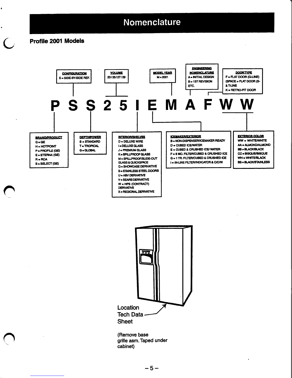
Profile
20/Jl
Models
C
-.
t
"**t"
t:-:
lrcoervrenl lnouerrcrrrune ll
po.nrYDE
I
I
M=2m1
| lA'NrnALDEscN llF-nxrDooR(c+lt{9 1
l--J
l8-lsrREvtstcftt I I
€mcE'FL{rDooR(9
I
I
ril
,,ll:@l
r
I;-
PSS2sIEMAFWW
n
o
Location
Tech Data
Sheet
(Remove
base
grille
asm.Taped
under
cabinet)
-5-
IBAtrENOIUCI
GrGE
H- HOTFOINT
P-PFOFI-E(OE)
E.ETERM(oE)
BT
RCA
S:SEECT(GB
ICETIICEET]EENE
B- Mll+otSPEilSEMCEM
IGR READf
D. CUBED
ICEAYAT€R
E. drBED
t CBUSIIED
ICE/W tER
F- G
ftlO. FILIER
CUBED
t CR SI{ED ICE
G
.
1 YR
FILTERDUBED
t CFT SHED
ICE
| . ll&UNE
FILTEMNDICAIOf,
t Clc/W
ItrIEEOEEUE.IES
D-DEIJ)GWRE
ITDELIJGGI.ASS
J.PBEMIUMGlrSS
K.SP|ITPFC,OFGLTSS
M:SPl1gr6g9P6119g6g1
Grrss&orrcKsnc€
O - SIIO,UCASE DEFIVATIVE
S r SitrlNLESS SIEEL
OOORS
U-AErVOlgl||VAIfVE
v.SE
FSDERI\AIIVE
W
r
HPS
(CO0{TFAGT}
DEHVtrryE
X.REOIOMLDEHVAnVE
EGEOECOIOB
UVW. WHlTElfllfTE
AATA.IIONUAIIOND
EBrE.A€l(BrlCl(
@rEISQUE/BISCUE
WHrlYl{TE/tslliq(
SSrH-SXlSlAllt[-ESSI
Page 8

Sales
slip or canoel,ed
check
is rquird
as
prcd
of
ortginal
purchase
date to obhin *ruioe
under
waffanty.
Allwananty seruice
is
provided
by our Fadory
Seruie
Centers
or
an authorized Customer Care@
technician.
(
c
Any
part
of the refrigerator
(excluding
water filter cartridge) which fails
due to a defect in materials
or workmanship.
During this full on*year
warranty,
GE
will
also
provide,
fre of
chatge,
all labor
and
in-home
servioe
to replace the
defective
part.
Any
part
of the
seated
refrigerating
system
(the
compressor,
condenser, evapoftltor,
and all
connecting
tubing) which f,ails
due to
a
defect in materials
or workmanship.
During
this fiveyear wananty,
GE
wiff
afso
provide,
free
of charge, all
labor and
in-home
service to replace
the defective
part.
Any
s*through
pan
or drawerturnished
with the
refrigerator
if
the
pan
or drawer breaks
during normal household
use.
Drawer covers
are not
included.
Any
part
of the water filter
cartridge
which
fiails due to a defect in
materials
or workmanship.
During
this
fuIt
thirty4ay waftanty, we will
afso
provide,
tree of
charge, all
labor and
in-home service
to
replace
the
defective
part.
.
Service trips
to
your
home
to teach
you
how to use
the
producl
.
lmproPerinstallation.
.
Failure of
the
product
if it is
abused or
used
for other
than
the
intended
purpose
or used commercially.
.
Loss of
food
due
to
spoilage.
.
Replacement
of
the water filter cartridge
due
to water
ptessure
that is
outside the
specified
operating
tange or due to
exces-
sive
sediment
in the water supply.
.
Replacement
of
water filter cartridge
after
its expected
useful
life,30 days.
e
Damage
to
the
product
caused by accident,
fire,
floods, or
acts of God.
'
Feplacement
of
house fuses or resetting
of
.
tncidentat
or
consequential damage caused
circuit breakers'
by
possible
defects
with
this
apptianoe.
This
wananty is ertended
to
the
original
purchaser
and any succeeding
ovvner
for
products purchased
for home
use within
the USA.
ln
Alaska, the wananty
excludes
the crist
of
shipping or seruice
alls
to
your
home.
Some sfafes
do
not allow
the
exclusion or
limiktion
of incidental
or
@nsequential
damages.This
war-
ranty
gives
you
specific
legal ights, and
you
may
also have
other
rights
which vary
from
state to state.
To
know what
your
legal
rights are, consult
your
local
or
state @nsumer
afkirs
office or
your
sfafe's
Attomey
General.
Warrantor: Genenl Eledric
Company.
Louisville,
l<Y
tt025
c
-6-
Page 9
Table
of
Contents
Fresh
Food/Freezer
lndependent Operation..
....
-..
8
Normat
Operating
Characteristics,
but Different
from
Prcvious
Models
.... ... I
Abnormal
Operating Characteristics
(lnconect Operation)....
. -.....
8
Adaptive
Defrost.
.-.---
8
GoolingOperation(AdaptiveDefrost)
.--- 9
Pre-Chilt
Operation
(Adaptive
[lefrost)
.....
. . . 9
Defrost
Heater
Operation
(Adaptive
Defrost)
... 9
Dwell
Period
(Adaptlve
Defrost)
....
9
Post
[)ryvell
(Adaptive
Defros0.
..
... 9
Liner
Protection
Mode
..... -.
9
Electrpnlc
lcemaker
...
-....10
Dispensing
Functlons
..
.....
Qulck
lce
..
Door
Alarm
Dispenserlight
.-..--
10
10
10
10
Dispenser
Lock
Filters
Hinge
System
and
Door Closure
Airflow
(Cabinet
lnterior)
"Jelly
Roll"
Condenser
....
Main Control
Board
10
11
11
11
12
13
-7-
Page 10
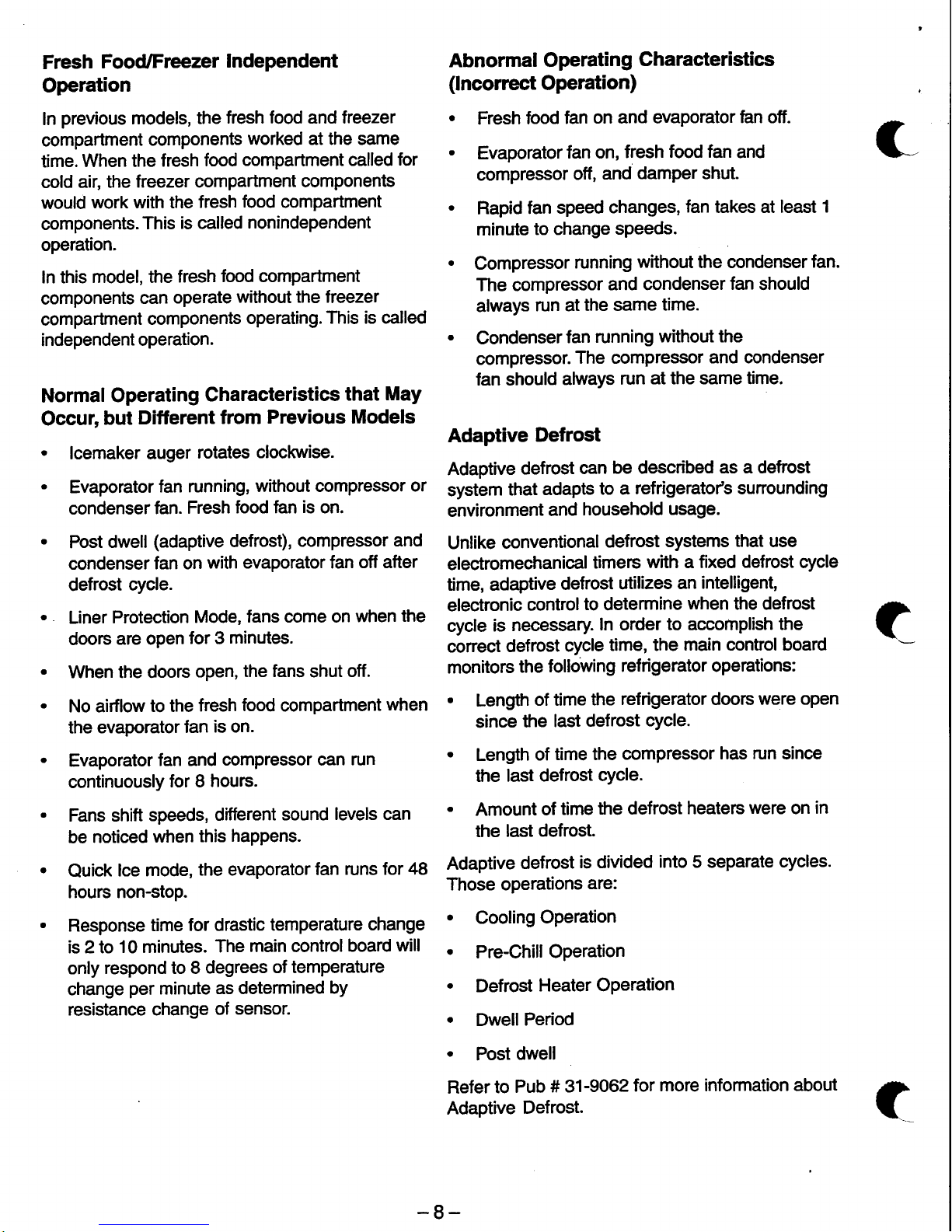
Fresh
Food/Freezer
Independent
Operation
fn
previous
models, the
fresh food and treezer
compartment
components
worked at the same
time.
When the
fresh
food
compartment called
for
cold
air, the
freezer compartment
components
would
work with the
fresh
food
compartment
components.
This
is
called
nonindependent
operation.
In this
model, the
fresh
food compartment
components
can
operate
without the freezer
compartment
components
operating.
This is called
independent
operation.
Normal
Operating
Characteristics
that
May
Occur,
but
Different
from
Previous Models
.
lcemaker auger
rotates
clockwise.
.
Evaporator
fan running,
without compressor
or
condenser
fan.
Fresh
food fan
is
on.
.
Post
dwell
(adaptive
defrost),
compressor
and
condenser
fan on
with evaporator fan
off after
defrost
cycle.
.
Liner
Protection
Mode,
fans come on
when
the
doors
are open
for 3 minutes.
.
When the doors
open,
the fans
shut
off.
.
No airflow
to the
fresh
food
compartment
when
the evaporator
fan
is on.
.
Evaporator
fan and
compressor can run
continuously
for 8
hours.
.
Fans shift
speeds,
different
sound
levels can
be
noticed
when
this
haPPens.
.
Quick
lce mode,
the evaporator
fan runs
for 48
hours non-stop.
.
Response
time
for drastic
temperature
change
is 2 to
10 minutes.
The
main control
board
will
only
respond to 8
degrees
of temperature
change
per
minute
as determined
bY
resistance change
of
sensor.
Abnormal Operating
Characteristies
(lncorrect
Operation)
.
Fresh
food
fan
on and evaporator
fan off.
.
Evaporator
fan on,
fresh
food fan
and
compressor
off,
and
damper shut.
.
Rapid
fan
speed
changes,
fan
takes at least
1
minute
to change
sPeeds.
.
Compressor
running
without the condenser
fan.
The compressor
and condenser
fan
should
always
run at
the same
time.
.
Condenser
fan running
without the
compressor.
The compressor
and condenser
fan should
always
run
at the same time.
Adaptive
Defrost
Adaptive
defrost
can
be described
as a defrost
system
that
adapts
to a
refrigerato/s sunounding
environment
and
household
usage.
Unlike
conventional
defrost
systems
that
use
electromechanical
timers
with a fixed defrost cycle
time, adaptive
defrost
utilizes
an
intelligent,
electronic
controlto
determine
when
the defrost
cycle
is
necessary.
In order
to accornplish the
corect
defrost
cycle
time, the
main control board
mon
itors
the f ollowi
n g ref rigerator operations
:
.
Lengft
of time
the
refrigerator doors
were open
since
the
last
defrost
cycle.
.
Length
of
time the
compressor
has run since
the last
defrost
cycle.
.
Amount
of
time
the defrost
heaters
were
on
in
the
last
defrost.
Adaptive
defrost
is divided
into 5 separate
cycles.
Those operations
are:
.
Cooling
Operation
.
Pre-Chill
Operation
.
Defrost
Heater Operation
.
Dwell
Period
.
Post
dwell
Refer
to
Pub
# 31-9062
for
more information about
Adaptive
Defrost.
c
t
-8-
Page 11
r\
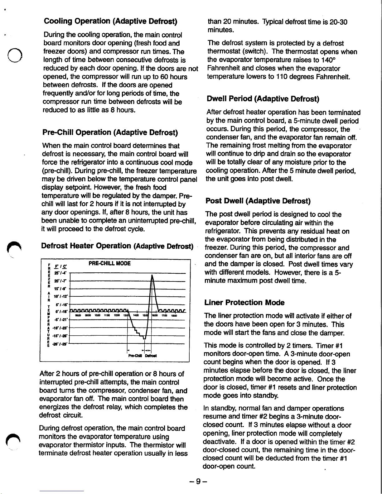
Cooling
Operation
(Adaptive
Defrost)
During
the cooling operation, the
main
control
board monitors door opening
(fresh
food
and
treezer
doors)
and compressor
run times.
The
length
of time between consecutive
defrosts
is
reduced
by each
door
opening.
lf the
doors
are not
opened, the compressor
will
run
up to
60 hours
between defrosts.
lf the
doors
are
opened
frequently
and/or
for
long
periods
of time,
the
compressor run
time
between
defrosts
will
be
reduced
to as
little as I hours.
Pre-Chill
Operation
(Adaptive
Defrost)
When the
main
control board determines
that
defrost is necessary
the main
control
board
will
force
the refrigerator
into
a cpntinuous
cool
mode
(pre-chill).
During
pre-chill,
the freezer
temperature
may
be
driven below
the temperature
cpntrol
panel
display setpoint.
However,
the fresh food
temperature will be regulated
by the
damper.
Pre-
chill will last
for 2 hours if it is not
intemlpted
by
any door openings.
lf,
after I hours,
the
unit
has
been
unable
to complete
an uninterrupted
pre-chill,
it
will
proceed
to the
defrost
rycle.
Defrost Heater Operation
(Adaptive
Defrost)
After 2 hours of
pre-chill
operation
or
8 hours
of
intemlpted
pre-chill
attempts, the
main control
board turns the
compressor,
condenser
hn,
and
evaporator
fan off. The main
control
board then
energizes the defrost relay, which
completes
the
defrost circuit.
During
defrost
operation, the main
control
board
monitors the
evaporator
temperature
using
evaporator thermistor inputs. The
thermistor
will
terminate
defrost
heater operation
usually in
less
than 20 minutes.
Typicaldefrost
time
is 20-30
minutes.
The
defrost system is
protected
by a defrost
thermostiat
(srlitch).
The
thermostat
opens when
the evaporator temperature
raises
to
140"
Fahrenheit
and closes
when
the evaporator
temperature
lowers
to 110
degrees Fahrenheit.
Dwell Period
(Adaptive
Defrost)
After defrost heater
operation
has
been terminated
by
the main
control board,
a S-minute
dwell
period
occurs.
During
this
period,
the
compressor,
the
condenser
fan,
and the
evaporator fan
remain
off.
The remaining frost melting
from
the
evaporator
will continue to
drip and drain
so the
evaporator
will
be
totally
clear of
any moisture
prior
to the
cooling
operation.
Afterthe
5 minute
dwellperiod,
the unit
goes
into
post
dwell.
Post Dwell
(Adaptive
Defrost)
The
post
dwell
period
is
designed
to
coolthe
evaporator before circulating
air within
the
refrigerator.
This
prevents
any
residual
heat
on
the evaporatorfrom
being
distributed
in the
treezer.
During
this
period,
the
compressor
and
condenser
fan are
on, but
all interior
fans
are off
and the
damper is
closed.
Post
dwelltimes
vary
with different models.
However,
there is
a
5-
minute maximum
post
dwelltime.
Liner Protection
Mode
The
liner
protection
mode
will
activate if
either of
the doors have been
open for
3 minutes.
This
mode willstart
the
fans
and
close the
damper.
This mode is controlled
by 2 timers.
Timer #1
monitors
door-open
time.
A
3-minute door-open
count begins
when
the
door is opened.
lf
3
minutes elapse before
the
door
is
closed,
the liner
protection
mode will
become
active.
Once
the
door
is
closed, timer #1 resets
and liner
protection
mode
goes
into
standby.
In
standby,
normalfan
and
damper
operations
resume
and
timer
#2
begins a 3-minute
door-
closed count. lf 3 minutes
elapse without
a
door
opening,
liner
protection
mode will
completely
deactivate. lf a door is
opened within
the timer #2
door-closed
count, the remaining
time in the
door-
closed count will be
deducted from
the timer #1
door-open
count.
n
PRE4HILL TIODE
I
erc
I
stt
I
a.rt
"
rtl.f
?
tar"t
T
'r-tt
I
o'r.rr
2
st,ar'
F
A 40!l-,3'
T
X
-rfr-zr
!
eo'rar'
@ml@trsta
-9-
Page 12
Electronic
lcemaker
This
refrigerator is equipped
with
an
Electronic
lcemaker.
Refer to
Pub # 31-9063lor more
information.
Dispensing
Functions
The
water, crushed
ice, and cubed ice functions
are controlled
by the
main
control
board.To select
a function,
press
the
appropriate
pad
on the
dispenser.The LED
will
light to identify
the
selection.
To dispense
the selected
item,
depress
the
dispenser cradle
located
in the
dispenser
re@ss.
The solenoid and
linkage
assembly will open the
ice
chute door
to dispense
the ice. lf
cubed
ice is
selected, the
crushed
ice
bypass solenoid will
allow cubed
ice to bypass
he
ice
crusher.
The
ice
chute door
must remain
open for 5 seconds after
dispensing
ceases.
After
this
S-second
delay, the
solenoid
and
linkage assembly
will
shut
the icp
chute door.
The
dispenser
light
will come on automatically
when the dispenser
cradle
is
depressed and
will
fade out 5 seconds
after
it is released.
The dispenser
selection
is recorded in the main
control board.
ln the event
of a
powerfailure,
the
last selected function
will be
restored.
Quick
lce
The
quick
ice
feature is available
on
some
models.
This feature causes
the evaporator fan to operate
non-stop tor 48
hours
(fan
may operate in high or
low
speed).
This enables
madmum icemaker
ouFut
The
QUICK
ICE
pad
initiates
the
quick
ice mode
in the refrigerator.
Pressing
the
QUICK
ICE
pad
lights the LED and sets
the
evaporator fan to
run
at medium
speed
(unless
the main controlboard
selects
high speed)
for a
48-hour
period.The
evaporator
fan is
terminated during defrost, dwell,
post
dwell,
and door
openings.
The
quick
ice
selection
is stored
in
the main
control board.
The
function
will
be restored
in
the
event of
a
power
failure.
Door Alarm
The DOOR AIARM
pad
is used
to tum on and
tum off
the door
alarm feature.
lf
the
feature
is on,
the DOOR
ALARM LED
willflash
when the
door
is
opened.
lf the door
is
open
for more than 2
minutes,
the door
alarm
will sound.
The
alarm can
be stopped
by
pressing
the DOOR
ALARM
pad
or
by shutting
the door.
lf
the
DOOR
ALARM
pad
is
pushed
while
the door
is open, the alarm willstop
but the
led
will continue
to flash untilthe
door is
closed.
When
the door
is closed it will reset
the
audible
alarm.
This feature
will
be retained in the
event of a
power
failure.
Dispenser
Light
The LIGHT
pad
tums the
dispenser light
on and
off.
When
the light
is
tumed
otf,
it
will
fiade
out. The
dispenser
light
will come on automatically when
the
dispenser
cradle
is
depressed
and willfade out
5 seconds
after
it
is released.
The
LIGHT
pad
will
not tum off
the light during
dispense.
Dispenser
Lock
When
the
dispenser
system is
locked, no
dispenser
command
will be
accepted.
This
includes
the dispenser
cradle
and will
prevent
accidental
dispensing
that
may
be caused by
children or
pets.
lf a
pad
is
pressed
with
the
system
locked,
it will be acknowledged with
3
pulses
of
the LOCK
LED accompanied by an
audibletone.
To lock
or
unlock communication between
the
dispenser
and the
main
control
board,
press
the
LOCK
pad
and
hold it for 3 seconds. The
LOCK
LED
willflash
while the LOCK
pad
is
pressed.
\Afhen
the
communication
is locked,
the LOCK
LED
will be
illuminated.
The status
of other
functions, selected
prior
to the
initiation
of
the
lock
feature, will be
displayed. lf the
lock is engaged
while a
mode is
active,
the LED
will remain
on untilthat
mode times
out.
lf the
lock
is engaged
when the
filter
timer
expires,
the LED
willcome
on
but
cannot be reset untilthe
lock is tumed
off.
The lock
feature
will be retained
through a
power
outage.
r
-
10-
Page 13

o
Filters
The
FreshSaver
filter is located
on the
FRESH
PRODUCE drawer
and will last for 1
year.
Some
models
are equipped
with a FreshSaver
FILTER
LED. After
1
year
of
refrigerator
operating time,
the FreshSaver
FILTER LED will illuminate
as
a
reminder to
the
ownerto change the filter.The
LED
can
be
reset
by
pressing
and
holding
the HOLD
3
SECS
pad
for 3
seconds. The LED will flash
while
the
pad
is
pressed,
remain illuminated
for
3
seconds after
the
pad
is released,
and
tum off.
Some
models
are
equipped with a water
filter that
is located in
the upper
right-hand
comer
of
the
fresh food
compartment.
Filters
are designed to be
used
for up
to
18 hours of
open
valve
time
or 1
year
of
clock
time.
When 90%
of
filter time has elapsed
(open
valve
time or
clock
time,
whichever
@mes
first),
the
main controlboard
willilluminate
the filter
reminder
LED
(amber).
When
10O/" of the filter time
has
elapsed,
the
main control board
will
illuminate the
filter
reminder
LED
(red).
Hinge System
and Door
Closure
The
hinge
brackets are
not
adjustable
on the
cabinet. The
fresh
food
door can be
adjusted up
and
down
by
using
the hinge
adjustment
pin
(located
on
the fresh
food lower
door hinge).
This refrigerator
is equipped
with
a
door opening/
closing
feature.
This
feature
consists
of a
spring-
loaded
arm
located
at
the
bottom of the
cabinet for
each
door.
The
arm
provides
a stop for
the door
when the door
is
partially
open and automatically
closes
the door
when the door is almost
closed.
IMPORTANT:
The
refrigerator rollers must
be
adjusted
correctly
for
proper
door closure. When
the rollers are
adjusted
correctly,
the
door should
close easily
when open approximately
45
degrees
(haltway).
Airflow
(Cabinet
Interior)
The freezer cabinet
is designed so that air is
drawn
into the bottom
of the airtunnel and through
the evaporator
when the evaporator fan is
operating.The
chilled air
is then
pushed
out
into
the top of the
treezer.
The fresh
food compartment
receives chilled air
via
an electronic
damper that is
positioned
at the
top
rear
of the refrigerator between the
freezer
cabinet
and
the fresh
food
cabinet.
The
damper
is
controlled
by the
main control
board and
when
open,
allows
chilled air
from the freezer
air
tunnel
to
move
into
the fresh food air tower. The fresh
food air
tower contains
a fresh food fan which
draws
chilled
air
from the freezer
(through
the
damper)
into
the
air
tower.
The
air tower directs
chilled
air across
the top of the
fresh
food cabinet
to
two
outlets. The
air tower also directs
chilled
air
down
the
back
wall of the
fresh
food cabinet.
The
chilled
air exits
the air tower
through vents in the
tower.
Air
retums from the
fresh food
cabinet
to the
treezer cabinet
via a
mullion located to the left of
the
FRESH
PRODUCE drawer.
AIR FLOW
+,
i,
H
ilr -l
\Er'-
lt..u/
lr
-!
UI\/
1LJ"
o
n
aoenl reenfil
-11-
Page 14
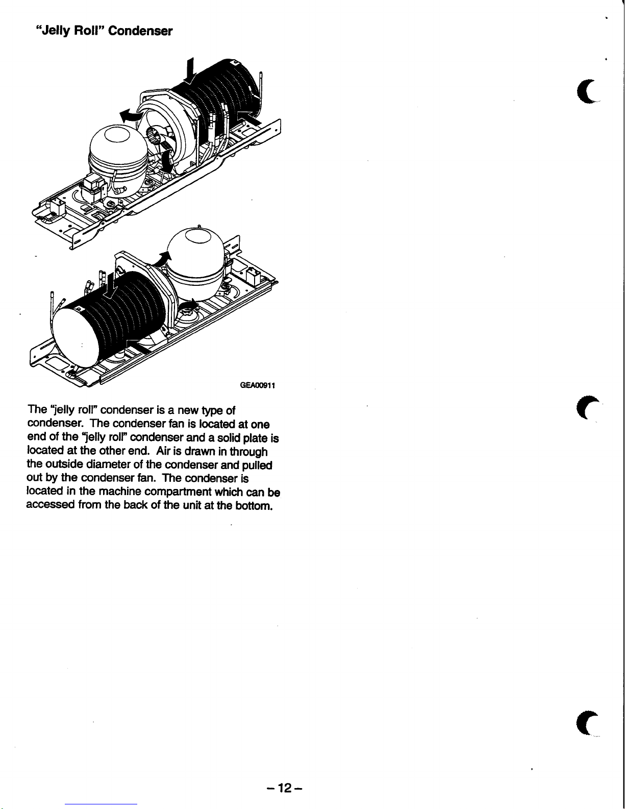
"Jelly
Roll"
Condenser
The
"jelly
roll"
condenser
is a new
type
of
condenser.
The condenser
fian is
located
at one
end
of
the
"jelly
roll" condenser
and
a
solid
plate
is
located
at the other
end. Air
is
drawn
in
through
the
outside
diameter
of
the
condenser
and
pulled
out
by
the condenser
fan.
The
condenser
is
located
in the
machine
compartment
which
can
be
accessed
from
the back
of the
unit
at the
bottom.
(
-12-
Page 15

Main Control
Board
INPUTS
ACCUMUI-ATED
FF
AND FRZ
DOOR OPENTNGS
(MINUTES)
COMPRESSOR
RUNNilE
(MTNUTES)
DEFROST
HEATER
OI{ TIIIE
(MTNUTES)
->
.|>
->
I
oUTPUTS
i
COOUNG
PRE-CHILL
DEFROST
<.
+
<-
n
i------lr-
----'t----,
ico||xt[rcattoil
ll ourpen
|
:ncooen
ll
THEhrstoa
i
roDEL
:
|
!'o'tfio{rrpur
tl
@[s
I rwuts
11
NRfGi
i
*
;
!!!s3
tlo
o o o
oliilo
o
o oio
rt:_-_---_e1t
rt_
r----,'
'=
n
---i--,t----l.?
oooo:oooooo
-13-
Page 16
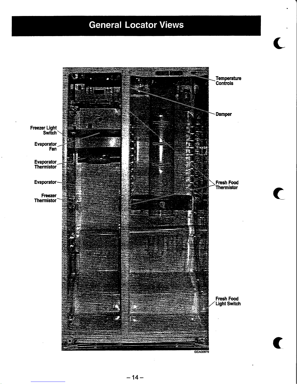
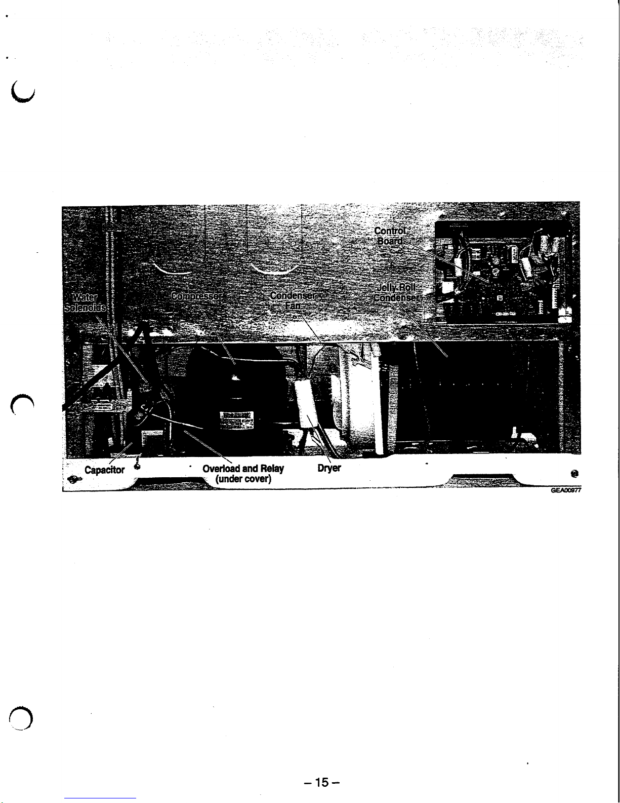
Temperature
Controls
Frcezer Light
Switch
Evaporator
Fan
Evaporator
Freezer
Thermistor
Evaporator
Thermistor
Fresh Food
Thermistor
Fresh
Food
Light
Switch
c
-14-
Page 17
o
o
"
gapacfior
-
vvt,rKras
dlls nElay
etra
o
ie"
'
.-ruF-'', (::dercove0
_.
_**
-
,,o.
==, =*,
GEA(E,''
-15-
Page 18
Table
of
Gontents
Door
Handle
18
Door Gasket
18
.
.:
Fresh Food Compartment Quick
Access Door
.
Fresh
Food Door
Light
Switch
19
Fresh Food Gompartment
Door Shelves
Fresh
Food Compartment
Shelves
. ..
19
Fresh
Food Compartment
Drawerls ... ....:.,:
....
19
Fresh Food Compartment
Ughts
Water Filter
20
Fresh Food
Fan and
Mullion Damper.
....,...
20
D,eli
Fresh Damper
FreshFoodThermistors..
r.!i,
21
Temperature
Gontrol
Panel
n
Freezer Door
Bins
.
22
Doors and
Door
Hinges
Uz
Fresh Food
Door Adjustment.
..
23
Rollers
23
Roller Adjustment
..
24
Freezer Compartment
Shelves
and Bins.
24
Freezer
Door Light
Switch
24
lce Dispenser
.
24
lce
Dispenser
Auger Drive and Cube Solenoid
lcennaker
25
?s
-16-
Page 19
Frcezer
Light
..........
.,.,.
26
Evaporator
Fan
. '... -
26
Evaporator
Thermistor...
.....,
27
Defrost
Thermostat
27
Defrost
Heater.
27
EvaporatorDriPPan.
"""
28
Evaporator...
.
Freezer
Thermistor....
.. '..
Condenser
Fan.
.....,..r.
Main
Processor
Gard
r.........
Water
Solenoids
...
-,.....
28
a
n
n
C
-17
-
Page 20

Door Handle
The door handles
allow
access into
the
fresh food
and freezer compartments. They
are front
mounted with 1 Ton
head
screw.
With a small flat-blade screwdriver,
slide the
handle trim down and
pull
it
out.
Remove the lower Torx head
screw.
Lift
the
handle in and upward motion
until
it
disengages the
locking tabs.
Pullthe
handle
outward to
remove
it.
Door
Gasket
The
door
gasket
is
a
molded
gasket
set into
a
channel located
in
the
door
liner.
1.
Open
the
door.
2. Grasp the
gasket
and
pull
in an
outward
motion untilthe molded
gasket
separates
from
the door liner.
Fresh
Food
Compartment
Quick
Access
Door
The fresh icod
compartment allows access
to the
fresh
food
compartment
without opening
the
fresh
food
door.
1.
Open
the
quick
access door
and remove
the
hinge
Tox head screws
(2),
located
on
each
side of the door.
With a small
flat-blade screwdriver, remove
the
door
frame and
door
frame assembly.
Remove the
gasket
and
slide
the door
out of
the frame.
The
quick
access door also
has
an
interlock
switch
located
at
the top
right-hand
side
of the
interior frame. Remove
the
Phillips
screw
and
slide the switch assembly
down and out.
Disconnect
the
wires
to the switch and remove
it.
C
1.
2.
3.
Rir'.
ffi.'
te
16:
*,r:
u.
k.
i:;
t
x
N:.
i.
I
t'
i.
f:-"--
t
i'
t.
:'
;.
!1'l
l:
'
i:::
't
GEA00922
-18-
Page 21

Fresh
Food
Door
Light Switch
In
addition
to
the
quick
access
door
light swttch,
the fresh food
compartrnent
has
a door
light
sntitch
located in the
lower
right comer
for the
compartment.
1.
Use a
small flat-blade
screwdriver
to
unlock
the locking
tab tabs
and
pullthe
switch out until
the
wire connector
is
visible.
2. Disconnect
the connector
and
remove the
switch.
Fresh Food
Compartmenl
Door
Shelves
The
door shelves
allow storage
of
perishable
items.
1. Tilt the shelf
up
and slide
it out.
Fresh Food
Compartment
Shelves
These shelves
allow
the storage
of
larger
items
and
pull
out
for easy
access.
1. Pull the
shelf
out
until
the shelf stop
tab meets
the compartment
stoP.
2.
Push the
shelf
stop
tab
down and
pullthe
shelf out
until
it is
removed.
Fresh
Food
Compartment
Drawers
Fresh
irod compartment
drawers
are designed
for
storage
of
fruils,
vegetables, and deli
items.The
drawers
are
located
in
the lower
portion
of
the
fresh
frood
compartment.
Pull
out
the drawer until
the rollers meet
the
mechanical
stoP.'u''
Tilt the
drawer
up
and
pull
it out
until
it is
removed.
Fresh
Food Compartment
Lights
The fresh
food
compartment
lights are
located
in
the upper
and
lower
portion
of
the fresh
food
compartment.
1.
To access
the
upper
lights,
remove the upper
opaque
cover
by unlocking
the tabs and
pulling
the cover
down.
1.
n
GEAfiIg28
GgA0@9
GEAOGIT'
-19-
Page 22

GEA{'GfiI
GEAOoSTO
2.
3."
To
access the
lower lights,
pullthe
delifresh
damper
adjusting
knob off.
Lift the
opaque
cover off the
tabs.
,
Water Filter
The waterfilter is
located
in the
upper right-hand
portion
of the fresh food compartrnent.
The
water
filter, filters uater for the
ice
maker
and the
water
dispenser. An LED
on
the
temperature
control
panelwill
illuminate when the filter
needs
to be
changed.
1. Turn the water filter 112 turn counterclochryise
and
pull
it
down.
2. To installthe
filtet
push
it up
while
turning 1/2
turn clockwise. Do not
force
the
filter.
Fresh
Food Fan and Mullion
Damper
The
fresh food
compartnent fian is located
under
the upper dustwork in the fresh
frcod
compartnent.
This fan
distributes
cold
airfrom the
lreezer
via
the
mullion
damper.The
mullion damper
is
located
in
the
same assembly as
the fan.
Both
are
controlled
by the
prccessor.
1.
Remove
the
delifresh adjusting
knob
and
light
cover.
2.
Unlock
the upper
and
lower
locking
tabs
for
the
center ductwork and
remove.
The
ductwork
is
also
fastened
with double-sided
tape
at
the
upper and
lower
portions.
GEA0oSI
GEA@982
-20-
Page 23

3.
Remove
the
upper
water
filter cover.
4.
Unlock
the
upper
opaque
light
cover tabs and
remove
the
cover.
5. Unlock
the
upper
ductwork
tabs
and remove it.
9.
Lay the fan
and damper
assembly
against
the
compartment
and
open the
back cover.
10. Disconnect
the
wire connections
and
remove
the damper
or
fan.
6. Remove
the
Phillips
head
screws
(8)
for
the
upper
light
assembly
plastic
bracket-
Pullthe
stainless
steel
light
bracket
down until
the
wires
are exposed
and
disconnect
them.
Remove
the
Phillips
head
screws
(2)
for the
fresh food
fan
and damper
cover
and
remove
the cover.
Deli
Fresh
Damper
The
delifresh
damper
is
located
at the bottom
of
the
cold
air ductwork.
lt allows
the
flow
of cold
air
to be
adjusted
to the
delifresh
drawer.
1.
Remove
the
delifresh
damper
adjusting
knob
and
the
lower
light cover.
2.
Remove
the
center
ductwork
by
unlocking
upper
and
lower tabs.
Double-sided
tape
is
applied
to upper
and
lower
areas.
3.
Remove
the
damper
Phillips
head mounting
screws
(3)
and
remove
the damPer.
Fresh
Food
Thermistors
The
fresh
food thermistors
are
located at
the
upper
and
lower
portions
of the
fresh
food
compartment.
They send
temperature
signals
to
the
processor.
7.
n
oEAOO$4
GEAO09I5
GEA00938
GEAO09S6
-21
-
Page 24

1. \Mrth
a small flat{lade
screwdriver,
unlock
the
tabs
and
remove
the
assembfy.
Remove the
thermistor from the
cover
and
disconnect the wire
connector.
Temperature
Contnol Panel
The
temperature
control
panelis
located
in
the
fresh food
comparFnent and mounted
atthe
upper
front.
This
panel
allows
temperature
control for
the
fresh
food
and freezer
compar[nents.
Eacfr
comparfrnent
has an LED readout
of
the
temperature
setting.
In
addition
the
panelhas
an
LED
readout for
water filter
change.
1. Remove
the control
panel
Phillips
head
mounting
screws
(3).
2. Pullthe
paneldown
untilthe
wire
connections
are exposed.
G€ m.F
Disc-onnect
the
panel
wire connector.
Disconnect
the circuit card ribbon.
Unlock
the
cad
locking tabs
located
at the
lower
lefi-
and
right-hand
oomers
of
the
card.
Remove
the
card.
Frcerer
Door Bins
The
freezer
door bins are located
on
the
inside
of
the freezer
door and tilt
out
to
allow
easy
access
of frozen items.
1. Tilt
the
bin
up and slide it
out
of
the
door.
Doors and Door
Hinges
IMPOffiANT:
The freezer
door
is
not
adjustrable.
The
fresh food door can
be adjusted
up
and down
to match
the
height
of
the
freezer
door.
Adiust
the
fresh
food door up or down using
the
hinge
adjustrnent
pin
(located
on the fresh
food
door
lower
hinge).
IMPORTANT:
The refrigerator rollers
must
be
adjusted
conecdy
to
ensure
proper
door
closure.
Refer to
the
Roller Adjusffnent
section
in
this
.
chapter for
more information.
1. Remove the base
grille.
2. Wih
the
door in
the closed
position,
disconnect the wiring harness
connector.
3. Disconnect the water
supply tube. To
disconnect
the tube,
push
the
white
collar
on
the
quick
connector
in
and
pullthe
tube
out.
4.
5.
6.
7.
GEAdXX]9
GEAO094e
GEAO@41
GEAOogrfi'
-22-
Page 25

4. Witr a
small
flat-blade screwdriver, disengage
the
locking
tabs of
the upper hinge cover
and
remove
it.
Remove
the
Tox head
hinge
scre\,\fs
(2)
and
lift
the upper
hinge
off the unit.
CAUTION:
Do
not side-load
hinges.
CAUTION:
Freclzer
door only
-
Do not
allow the
connrtor
to
contact
the
floor. Hard
contact may
damage
the
connector.
NOTE:
Guide
the
waterline and wiring
harness
through
hinge
while lifting the
door from hinge.
6. Open
the
door
90o and
lift
door straight up and
off
the
lower
hinge.
Thlmbb
Hlnge Pln
Torx Scrprv
6EAOO90I
Lower
Hinge, Freezer Side
7.
Remove
the
Tox screws
(3)
and
the lower
hinge
from
the
cabinet.
Thimbb
Hinge
\--Torrscre*
Lower
Hinge, Fresh Food Side
Fresh
Food
Door Adjustment
IMPORTANT:
The freezer door is not adjustable.
The
fresh
food door can be adjusted to
match the
height of
the
freezer door.
IMPORTANT:
The refrigerator rollers must be
adjusted
conectly
to ensure
proper
door closure.
Refer
to the
Roller Adjustment
section in this
chapter
for more information.
1. Remove
the
base
grille.
2.
Turn
the
hinge adjustment
pin
(located
on the
fresh food
lower
hinge)
clockwise
to raise
the
door
level and
counterclockwise
to
lower the
door.
Rollers
This unit
has
4 rollers
for
easy
movement
of the
refrigerator.There
are
2 rollers
located in the
front
and
2
rollers
located
in the rear of the unit.
IMPORTAM:
The reftigerator
rollers must be
adjusted
properly
to
ensure
proper
door closure.
Refer
to
Roller Adjustment.
1.
To
remove
the front
rollers, back the level
adjusting
screw all
the
way
out.
2.
Remove
the
1/4-in. roller
mounting screws
and
remove
the caster.
To
remove
the
rear rollers,
remove 114-in.
mounting
screws
(2).
Tilt
the
roller
down and slide
it out.
Hlngc
ffJ"*".".
GEqOOtXa
GEA0G'15
-23
-
Page 26

1.
2.
Roller Adjustment
The
front
(2)
rollerc are adjustable.
Adjust
them
so
that the refrigerator
is solid and the
doors close
easily.
Remove the base
grille.
With
a flat-blade screwdrivel
tum
the
adjusting
screw clockwise to raise
the roller
and
counterclockwise
to lower
the roller.
Freezer
Compartment Shelves and
Bins
The
shelves
and bins slide
out
for easy access for
frozen items.
1.
Slide
the
shetfibin out
until
it
reaches
its stop.
2. Tilt the
shelfibin up and slide it
out
of the
compartment.
Freezer
Door Light Switch
This
switch is located in
the
left-hand
portion
of
the freezer
compartment and sends
a signalto
the
processor.
1.
With
a
small flat-blade screwdriver,
unlock
the
locking
tabs and
pullthe
switch
out
untilthe
wire
connector
is
visible.
2. Disconnect
the wire connector and remove the
switch.
lce
Dispenser
The ice
dispenser
is located in the
upper
portion
of
the freezer
comparhnent.
This
assembly stores
ice
made by the
icemaker
and dispenses
ic€
on
demand from the door dispensertarget
switch.
1.
Remove the
upper
ice bucket tray.
2. Slide out the
ice
dispenser assembly.
Remove the
ice
cube solenoid linkage Phillips
head
screw
and slide the linkage
back.
Remove the
ice
crusher cover Phillips head
screws
(2)
and
remove
the
cover.
With a
pair
of
pliers,
twist off the
backing
plate
tabs located
on either side of the
crusher.
c
GEAO€46
GEA00947
GEAO€5o
Page 27

7.
With 2
smallflat-blade
screwdrivers,
unlock
the
ice
crusher
locking
tabs
located
at either
side
of
the
ice
crusher-
Lift the
ice
crusher
out
of
the
bucket.
8.
Remove
the
ice crusher
bac*
cover.
9.
Remove
the
locking
ring
from
the
ice crusher
auger.
10.
Remove
the
plastic
nut
with
a
pair
of
pliers
by
tuming
it
clockwise.
11.
Remove
the
spacers
and
blades.
The blades
are
numbered
for
reassemblY.
lce
Dispenser
Auger
Drive
and
Cube
Solenoid
The
ice
dispenser
drive
motor
and
cube
solenoid
are
located
in
the
upper
rear
of
the
freezer
compartment.The
drive
motor
rnoves
the auger
via a
fork
located
on
the
drive
motor.The
cube
solenoid
allows
cube
or crushed
ice to
be
dispensed
on
demand-
1.
Remove
114'in.
housing
mounting
screws
(4)
located
at
the
four comers
of
the
housing.
2. Slide
the
housing
forward
untilthe
connector
is
visible,
disconnect
the connector,
and
remove
the unil
from
the
housing.
Note:
Drive
fork
has
reverse
threads;
tum
clockwise
to
remove.
3.
Remove
the
fork
from
the
drive
motor
by
tuming
it clockwise.
4.
Disconnect
the
motor
connectors
and
remove
the
ground wire.
5.
Remove
1l4-|in.
mounting
screws
(3)
and
remove
the
motor.
6.
Dismnnect
the
cube
solenoid
wires.
7.
Remove
cube
solenoid
1/4-in.
mounting
screws
(2)
and
remove
the cube
solenoid.
lcemaker
The
icemaker
is
located
in the upper
rear
of
the
trwzer
compartment
and
supplies
ice to
the
dispenser
tub.
1.
Disconnect
the
icemaker
cable
connector.
2.
Remove
1l&in"
icemaker
mounting
screws
and
slide
out
the
icemaker.
This
relrigerator
is equipped
with an
Electronic
lcemaker.
Refer
to Pub
# 31-9063
for more
information.
-25-
Page 28

Freezer
Light
The
freezer
light is
located
in the upper rear
of
the
freezer
bompartment
The
light is
covered by an
opaque
cover.
1.
Unlock the
locking tabs and remove
the cover.
2.
Replace the
appliance
light
Evaporator
Fan
The
evaporator
fan
is located
in
the
upper rear
portion
of the
treezer compartment.
This
fan
supplies
cold air
to the freezer
and fresh
food
compartments. The evaporator
thermistor
must
be
replaced
when replacing
the fan.
1.
Remove 1lSin. icemaker
bracket screws
(4)
located at the four comers
of
the bracket.
2. Remove 1l&in.
ice dispenser
drive mounting
bracket screws
(2)
and remove
the brackets.
Remove 1lSin. upper
evaporator fan
duslwork
screws
(2).
Unlock the
tabs and
remove
the
lower
evaporator
fan ductrrvork.
Remove 1l#in, evaporator cover screws
(4)
and
remove the oover.
Remove
1l$in. upper
evaporator fan
duct work
screws
(2),
located at the
lower
portion
of
the
ductwork.
\ffith
a smallflat-blade
screwdriver,
unlock the
tabs for
the
icemaker and dispenser
cables.
Slide
the upper
fan ductwork out.
Disconnect the
evaporator
fan
wiring hamess.
4.
c
6.
7.
8.
9.
G8400855
GE400058
-26-
Page 29

10. Remove
the
1/4-in.
screw
for the evaporator
fan
ground
wire.
11. Remove
the
1/4-in.
evaporator
fan
bracket
mounting
screws
(2),
located at
either side
of
the bracket.
12.
Remwe
the evaporator
fan assembly.
Evaporator
Thermistor
The evaporator
thermistor
is
snapped
on to the top
portion
of the
evaporator.
This
thermistor
sends
evaporator
temperature
signals
to
the
processor.
The thermistor
must
be
replaced
when replacing
the evaporator
fan.
1. Complete
evaporator
fan
procedure.
2. Unsnap
the
evaporator
thermistor
from the
evaporator
and
remove
it.
Ilefrost
Thermostat
The
defrost
thermostat
is snapped
onto the
top
portion
of
the evaporator.The
thermostat
sends
temperature
information
to the
processor.The
detrost
heater
must
be replaced
when
replacing
the
thermostat.
1.
Remove
the
lower fan duct
work
from the
evaporator
cover.
2
Remove
the
1/4-in.
evaporator
cover screws
and
remove
the evaPorator
cover.
3.
Disconnect
the
defrost
thermostat
wiring
connector.
4. Remove
the
defrost
thermostat
from
the
evaporator.
Defrost
Heater
The
defrost
heater
is located
at the bottom
of the
evaporator.The
defrost
heater
heats the
evaporator
in
the defros{
mode of operation.The
thermostat
must be
replaced when replacing
the
defrost
heater.
1.
Complete
defrost
thermostat
procedure.
2.
Remove
Phillips
head defrost
heater
mounting
screws
(2).
3.
Remove
the
defrost
heater.
GEAOMG2
GEAO@63
-27
-
Page 30

n
Condenser
Fan
The condenser
fan
is located in the rear of the
unit.
It
provides
forced-draft
cooling
for the condenser
coil.
1. Remdve
the
1i4-in. back
panel
access screws
(5)
and
remove
the
back
Panel.
2. Remove
the
1/4-in.
condenserfan
mounting
screw and
slide
the
lan out untilthe
wire is
exposed.
3. Disconnect
the supply
wire connector.
Main Processor
Card
The main
processor
card
is located in
the
back of
the
unit.
This card
controls the operation of
the
unit. lf a fan short
has
occurred,
replace the
fan
prior
to
the card
or the card
will be destroyed.
1.
Secure
power
to the unit.
2. Remove
the
1/4-in.
processor
card
panel
screws
(10)
and
rernove
the
panel.
Disconnect
the
processor
cable
connectors.
Remove the
card by
unlocking
plastic
locks
located
at
the comerc
of
the card.
Water Solenoids
When
the solenoids
receive a signalfrom
the
processor,
they route
water to the filter, cooler, and
icemaker.
1. Remove
the 1/4-in.
rear
panel
screws
(10)
and
remove
the
rear
panel.
2. Remove
the
1/4-in.
bracket screw.
3.
Slide
the
solenoid
assembly out.
4.
Disconnect
the
cable assembly.
5. Disconnest
the
water
tube.
To disconnect
the
quick
connect,
push
the black collar
in and
pull
the
tube
out.
6.
Remove
the solenoid.
3.
4.
o
-29-
Page 31

r
-30-
Page 32

/t\
o
-31
-
Page 33

Table
of
Contents
Efficient
Use
of Diagnostics
...
g2
Failure
Gauses
(table
1)
...
......
3il
Self Diagnostics
......
3lt
Diagnostic
Tests
ftable
2)
.
. .
35
Communication
Tests
(0
2,
0 3, or
0 4)
. . .
35
Temperature
Control
Panel
Self-Test
(0
6)
.
gs
_
Dispenser
Board.
36
Control
and
Sensor System
Self-Test
pn.
r o i '
36
Main
Control
Board
(Low-Voltage
Side)
......
97
Main
Control
Board
(120-VAC
Side)
38
Main
Control
Board Locator
Table
(Low-Voltage
Side)
gg
Main
Control
Board LocatorTable (l2GVAC
Side)
40
Unit Dead,
No
Sound & No
Cooling
(diagnostic
chart)
42
Fresh
Food
Warm - FreezerWarm
(diagnostic
chart)
rt3
Fresh
Food
Warm - Freezer
Normal
(diagnostic
chart)
u
Fresh
FoodTooGold
-
FreezerNormal (diagnosilc
chart)
......
45
Freezer
Warm
-
Fresh Food
Normal
(diagnostic
chart)
rt6
Compressor
Not Running
(diagnostic
chart)
4T
Damper
Door
Not Opening
or Not
Closing
(diagnostic
chart)
g
Gondenser
Fan
Not Running
(diagnostic
chart)
49
Evaporator
Fan
Not
Running
(diagnostic
chart)
50
Fresh
Food
Fan Not Running
(diagnostic
chart)
Hearry
Frost
on Evaporator
(diagnostic
chart)
... . . .
52
ThermistorTest(diagnosticchart)
......
53
Thermistor
Values
(Iable
3). . .
54
Efficient
Use of
Diagnostics
For
the
most
etficient
use of the
diagnostics,
find
the
appropriate
diagnostic
chart and
proceed
as
directed
in
the
chart.
When directed
to
enter
Self
Diagnostics,
refer to the
Self Diagnostics
section of
this
chapter
for
more information.
When
directed
to
perficrm
a diagnostic
test
(example;
encoder
test
0
5), refer
to Table
2, Diagnostic Key
Sequences, for
more
information.
-32-
c
r
Page 34

t,
Table 1.
Failure
Causes
Freezer
Compartment
Fresh
Food
Gompartment
Above
15o
Fahrenheit
High-resistance
f reezer thermistor
Low
resistance
erraporator
thermistor
Condensor
tan
tailure
Erraporator
ian
tailure
Defrost
heater
stuck
on
Door
s'witch
failure
Main
control
board
f-aultY
Hamess
faulty
Dispenser
flap
oPen
Door
gasket
leak
Door
ajar
Sealed
system
failure
Above
5(P
Fahrenheit
High-resistance
fresh food
compartment
thermistor
Damper
closed
Fresh
food hn
failure
Evaporator
tan
failure
Door
srvitch
tailure
Main
control
board
faulty
Harness
faulty
Door
gasket
leak
Door
ajar
Cycle
Normal
(between 14o and
-14"
Fahrenheit)
Cycle
Normal
(between
49P and 33o
Fahrenheit)
Below
-15o
Fahrenheit
Damper
stuc*
closed
Low-resistance
in treezer
thermistor
circuit
Main
control
board
faultY
Fresh
food
compartment
fan failure
Harness
taulty
Below
32o
Fahrenheit
Damper
stuck
oPen
Low-resistance
f resh food
compartment
sensor
circuit
Main
control
board
faultY
Ambient
temperature
below
60o
Harness
faulty
)
Self
Diagnostics
To
enter
Self
Diagnostic
mode,
both
temperature
control
panel
displays
must be
illuminated.
A display
can
be
illuminated
by
pressing
an adjacent
temperature
adjustment
button.
When
both displays
are
ifluminated,
set
the
lreezer
anO
r*rigLratortemperature
settings
to 5.
Simultaneously
press
and
hold
all
4 temperature
adjustment
buttons
for approximately
3
seconds.
A flashing
0
in the
refrigerator
and
lreezer
displays
will
indicate
that the
refrigerator
is
in Self
Diagnostic
mode.
To
perform
a
self
diagnostic
test,
locate
the test
in
Table
2,
DiagnosticTests.
For temperature
control
panels
with
single-digit
displays,
the COLDER
temperature
adjustment
button
will increment
the
numbers
up
and the
WARMER
temperature
adjustment
button
will
increment
the
numbers
down.
Use
the
treezer
temperature
adjustment
buttons
to
enter
the test
code
number
in
the
treezer
display.
Use
the
refrigerator
temperature
adjustment
buttons
to
enter
the
test code
number
in
the
refrigeiator
display.
When
a
test code
has
been
entered,
the
displays
willflash
to confirm
the
test.
Press
the
HOLD
button
for 3
seconds
to begin
the
test.
For
temperature
cpntrol
panels
with
3-digit
displays,
the
COLDER
temperature
adjustment
button
will
increment
the
numbers
down
and
the
WARMER temperature
adjustnent
button
will
increment
the
numbers
up.
Use
the
freezer
temperature
adjustment
buttons
to enter
the
test
code
number
in the
treezer display.
Use
the
refriger:aior
temperature
adjustment
buttons
to
enter
the
test code
number
in
-33-
Page 35

the refrigerator
display.
When
a test
code has
been entered,
the displays
willflash
to confirm
the
test
code.
Press
any button other than
a temperature
adjust
button to
begin
the test.
When testing
has
been
completed,
do one of the following
things:
.
Enter code
1 5 to completely reset
the
system.
.
Enter
code
1 6 to exit diagnostic
mode. The temperature
control
panel
is reset
automaticatly.
.
Unplug
the refrigeratorfor at least
10
seconds. Test
mode willterminate
when the refrigerator
is
plugged
back in.
Test mode willterminate
automatically
after 15 minutes
of inactfuity.
c
r
Temperature
Control
Panel
(Single-Diglt
Display)
-u-
Page 36

Table
2. Diagnostic
Tests
Freezer
Dlsplry
Relrlgentor
Dlsplry
Modo
Commsnts
0
2
Temperature
control
panel
to
main
control
board
communicalion
P on
the FZ
disPlaY
if OK.
F on
the
FZ
disPlaY
if
not OK.
0
3
Temperafu
re control
Panel
to
dispenser
board communication
P
on
the
FZ
disPlaY
if OK.
F on
the
FZ
disPlaY
lf
not
OK.
0
4
Dispenser
board
to main
control
board
communication
P on
the
FZ
display
if OK
F
on
the FZ
disPlaY
if not OK-
0
6
Temperature
contol
Panel
self'
test
See
Temperature
Control
Panel
Setf-Test
on
page
35.
0
7
Control
and
sensor
sYstem
self-
test
See
Controland
Sensor
Self-Test
on
page
36.
1
0
Open
damper
Damper
will
open,
pause
briefly'
then
close.
1
1
Fan
speed
test
Each
fan will
run
br 10
seconds,
then
stop.
1
2
l(X)o/o run
time
This
mode
runs
the
sealed
sysfiem
100f:h
of the
time
br
t
hour.
1
3
Enter
pre-chill
This
places
the
freezer
in
prachill
mode.
The
refrigerator
will
retum
to normal
operation
on
its orvn.
1
4
Enter defrost
This
will
set
the
refrigerator
into
the defrost
mode.
lf
the
cabinet
is not
cold
when
executed,
ihis
mode
may
execute
extremely
fast
The
refrigerator
will
retum
to
normal
operation
on
its
own.
1
5
Refrigerator
reset
Causes
a system
reset.
1
6
Test
mode o<it
Causes
system
to
exit
test
mode and
resets
temperature
control
Panel
1
7
Degree
C/F
Refrigerator
temperature
adiust
keys
can
be used
to
change
displaY
from
F to C
or C
to
F.
o
CommunicationTests
(0
2,0
3' or
0
4)
A
communication
test
wiil display
the test
code
while
checking
communication.
When
the
test
has
concluded,
the
freezer
display
will display
a
P
(passed) or
an
F
(failed) for 2
seconds.
After 2 seconds,
the
displays
will show
the iesl
code.
At
this time,
a
new
test
code
can
be
entered.
Temperature
Control
Panel
Self-Test
(0
6)
This
test
applies
only
to
the temperature
control
board
inside
the
fresh
food
compartment.
When
the
Temperature
Control
Panel
Self-Test
is initiated,
all
of
the
LEDs
and
numerical
segments
in the
displays
will
illuminate.
when
the sAFE
THAW button
is
pushed,
all
3
LEDs
for
safe
thaw
should
turn
ofr.
wnen
the
QUICK
oHILL
button
is
pressed,
all 3
LEDs
for
the
quick
chill
should
turn off.
Continue
this
process for each
LED/Button
pair
on
the display.
The
colder
key
is to
turn
off
seven-segment
LEDs.The
warmer
key
is to
turn
ott ttre
Set
LED
for both
the
freezer
and
the
fresh
food
compartments'
To
exit
the
Temperature
control
panel
self-Test,
both
of
the
refrigerator
temperature
adjust
keys
must
Oe
fresseO
simultaneously
for 3
seconds.
This can
be
done
at any
time
to exit
the test.
f
-35-
Page 37

Dispenser Board
No self
diagnostic tests exist
for the dispenser
board.
Dispenser
board
operation
is tested
by
pressing
each button
and checking
for
proper
operation.
Control and Sensor System Self-Test
(0
7)
This test checks
all
fre thermistors located throughout
the
unit.
Once the
test is initiated,
the test
code
(0
7) will
stop
flashing and
the thermistor test results
will
appear on the
treezer display in the test
order
listed
below.
The thermistor
test sequence number will
not be shown on
the
display.
lf the
unit
is
not equipped
with
the
Quick
Chill option,
the third thermistor
(quick
chill)
will
display a 0 and
3 audible beeps will sound
at the temperature control
panel.
This is not
a
fiailure if
the unit is not
equipped with
the
Quick
Chill option.
Thermistor test resutts:
o
_P
=
Pass
.
0 = Failed
o
$=Shortto5VDC
o
l=Badamplifier
Thermistor
test sequence
is:
1. Fresh ficod
top thermistor
2. Fresh food
bottom
thermistor
3.
Quick
chillthermistor
(displays
0
if unit is not
equipped with
Quick
Chill
option)
4. Evaporator
thermistor
5.
Freezer
thermistor
Note: Thermistor
test
results will be displayed in the sequence shown above.
The thermistor test
sequence number
will
not be
shown
on the display.
-36-
Page 38

INPUTS
ACCUIIIULATED
FF AND
FRZ
DOOR
OPENINGS
(lrlll{uTEs)
COMPRESSOR
RUNTITIIE
(MTNUTES)
DEFROST
HEATER
ONTIME
(MNUTES)
Main
Control
Board
(Low-Voltage
Side)
I
I
I
------1
I
-
Blk
-
Red
-
Blu
-
Pur
-
whr
1
2
3
4
5
DAFCi
od,s
lt
rPu|ls
1
sE-Ecr
I
-
Red
-
Not Used
-
Btk/whr
-
Yel
-
Yel /
Blk
-wm
-
Blu /Wht
-
Blu
->
+
+
a
1
-Yel
2
-
Red/
Blk
3
-
Vtfht/
Brn
4-Blu/Yel
trtrtrutrtrtrtrtrtr
3
-
Fed/Wht
4 - Blu/Wht
ffiEltr
trtrtrtrtr
@@
r-
('-
l-
I.
ry
oooooloooo
oooioooooo
trtrtrtrtrtrtrtr
5
4
3
2
1
-37
-
cEA009o6
Page 39

Main
Control
Board (l2GVAC
Side)
C
I
I
I
I
I
I
I
I
I
I
I
I
I
I
I
I
I
I_
DEFROST
{-i
<-i
<-i
OUTPUTS
COOLING
PRE-CHILL
I
I
J7
1
-
Beige
2-Sal
3-Yel
4-
Red/Wht
5 - Blu
/Wht
-
Pur
7-Red
-
Not
Used
-
Orn
r
PROCESSING
UNlT
*#
EFE
utrtrutrDDtrtr
-38-
Page 40

C
n
o
Main
Control
Board
Locator
Table
(Low-Voltage
Side)
Connector
Pin
Wire Color
Component
Termination
Pin-to-Pin
Voltage Reading
J1
1 Blue/Red
Fresh
food
thermistor
#1
J1
pin
1
to
pin
5
=
2.8
to 3.5
VDC
J1
2
Yellow
Fresh
food
thermistor
#2
J1
pin
2 to
pin
5
=
2.8 to
3.5
VDC
J1
3
RedAilhite
Freezer
thermistor
Jl
pin
3 to
pin
5 = 2.8
to
3.5
VDC
J1
4 BlueM/hite
Evaporator
thermistor
Jl
pin
4 to
pin
5
=
2.8
to 3.5
VDC
J1
5
Blue
Thermistor
supply
voltrage
(5
VDC)
Jl
pin5toJ4pin3=5VDC
J2
1
Blue
Evaporator
fan
tachometer
J2
pin
1 to
pin
3 = 6.3
VDC
J2
2
BlueA/t/hite
Fan
input
J2
pin
2
to
pin
3
=
12
VDC
J2
3
\ /hite
Fan
common
J2
pin
3 to
pin
I
=
12
VDC
J2
4
Yellow/Black
Evaporator
fan
J2
pin
4 to
pin
3
=
12.4
VDC
(high
speed),
I
VDC
(low
speed)
J2
5
Yellow
Condenser
fan
J2
pin
5 to
pin
3
=
13.4
VDC
(condenser
fan is single
speed)
J2
6
BlackAA/hite
Fresh
food
fan
J2pinGtopin3=0VDC
(high
speed),
3
VDC
(low
speed)
J2
7
Not used
Not applicable
Not
applicable
J2
I
Red
Fan
supply
voltage
(12
vDC)
J2
pin
I to
pin
6
=
13.4
VDC
(high
speed),
9
VDC
(low
speed)
J2pinStoJ4Pin3=
13.4
VDC
Continued
on
next
Page.
-39-
Page 41

Main
Control
Board
Locator
Table
(Low-Voltage
Side)
Connector
Pin
Wire
Color
Component
Termination
Pin to Pin Voltage
Reading
J3 1 Yellow
Damper
J3pinltoJ4pin3=
Standing Voltage
2,3
VDC
Traveling Vohbge
6.0
VDC
J3
2 Red/Black
Damper
J3
pin
2to
J4
pin
3
=
Standing Voltage
2.3
VDC
Traveling Voltage
6.0 VDC
J3
3
White/Brown
Damper
J3pin3toJ4pin3=
Standing Voltage
2.3 VDC
Traveling Voltage
6.0 VDC
J3 4
BlueA/ellow
Damper
J3
pin
4to
J4
pin
3
=
Standing Voltage
2.3VDC
Traveling Voltage 6.0
VDC
J4 1 Black
Dispenser
board
@mmon
transmiUreceive
See schematic
J4
2
Red
Dispenser
board
common
12 VDC
See schematic
J4
3
Blue
Dispenser
board
common
ground
See
schematic
Continued
on next
page.
C
c
r
-40-
Page 42

Q
n
)
MainControl
Board
Locator
Table
(120-VAC
Side)
Connector
Pin
Wire
Color
Component
Termination
Pin
to
Pin
Voltage
Reading
J7
1
Beige
Auger
motor
J7
pin
1
to
J7
pin
9
+
120
VAC
J7
2
Silver
Cube
solenoid
J7
pin
2to
JT
Pin
9
+
120
VAC
J7
3
Yellow
Water
valve
J7
pin
3
to J7
pin
9
+
120
VAC
J7
4
RedMhite
Auger
motor
interlock
J7
pin
4
to
JT
pin
9 + 120
VAC
J7
5
BlueM|hite
Quick
chill
heater
J7
pin
5
to J7
pin
9
+
120
VAC
J7
6
Purple
Fresh
food
door
light
switch
feedback
J7
pin
6 to J7
pin
9
+
120
VAC
J7
7
Red
Freezer
door
light
switctl
feedback
J7
pin
7 to
J7
pin
9 + 120
VAC
J7
I
Not used
Not
used
Not used
J7
I
Orange
Neutnal
Neufal
-41
-
Page 43

Caution:
Unplug
power
when disconnecting
and
connecting
connectors
on
the board.
Unlt D,ead, No Sound & No Coollng
c
Ched(h12O/ACd6dn
csnecbra
terduit
lbyut
have 12O/AG?
Are the hterior ligtG m?
Ctre*
tslse st
pply
rclbge.
Doyullaw
l?fl,lrG.?
FsCacon[o|
b€tdandch€ck
d
fan notqs drcuit b shorb.
It shod
b d€ct€cled
tFeir sfioft c
l€ple fEl
mobr. Fallupto
ttCace sttqted
carpsrnt
will
cbnage
lhs nsw
corml bedrpn
fEtamiion
ItrphrgJ2
oqnecbfiutt
aontol bcrd.
Ctrd(tu12VDCel
contsdbcddnJ2€b
Jag Doyq.t
tmrwltag3
CtFc*
@sto€r
and t€mpefailt€
conffol lighEl
DotFyrcri?
lil.n Sade
Dlagnodc T.!t ( 07
)
Thonnisiortest - se€
pegs
33
for
€niledr€ dagtciic
ttbde
DotEifF
nisbrsts6i OK?
Fdbrvd $€F
inthe'f'&br
bstbffifiineprobltn
Fttn
Scilbe
DlegnodcTc.t( 1€
)
Prccill
-
see
page
3E|
fa eniefttg
senioedagtdics
Do€s rnitstarttonn?
-
42-
Page 44

Baslc
rafrlgerator
checlc:
Door
gasket
seal
OK?
Door switctr
-
light tuming off
with door closed?
Dispenser
duct door closing
propeny?
C
Fresh Food Warm - Frcezer
Warm
n
Run
Servlce Dlagnosilcr
Test
(o'D
Thermistor check
-
see
page
5{l
Did test
check
OK?
Run Sewlce
Dlegnostlcs
Test
(1{)
Prc€hlll'
see
page
3tl
for
entedng
diagnostic
mode
ls the condenser
fan running?
Goto
Evaporator
Fan
Not Running
Flovtrchan
page
50
ls
the evaporator
fan
running?
Unit
tests OK
Run cfiecks
again
Reset eleclronics
by
unplugging
refrigerator
for
15
seconds
-43-
Page 45

Fresh Food Waim
-
Freezer Normal
Check
control settings and temperaturcs
Food
at setting of 5 and 5
with no
door
opens for 12 hours should
be:
Fresh food
U"F
lo 42"F
Freezer
€oF
to
+6oF
I
Contd settings
OK
conrotsettings
ffi
"ffiI[*@
I
|
,"the
Freshroodfan
runnins?
-*-*l
t*
?fffiasnostict""t(1-1)
|
Yes
r
r
Tum unil
off
then back on!
Did the damperqrcle?
ls the
airffow
within
lhe
Fresh Food normal?
Check sealed s!6tem
Normal
trost
pattem
on evaporato?
Unit tests
OK
Run checks again
Reset
electronics by unplugglng
refrigerdor
for
15 seconds
Look for usage
problem
-M-
Page 46

Check
control settings
and temperaturcs
Controls
at a setting of
5 and 5
with
no door
openings
for 12 hours should
be:
Fresh Food 34"F
to 42"F
Freezer€F
to
6F
f
Fresh FoodToo
Cold
-
Freezer
Normal
Control
seftings
OK
n
Lonrambient?
ls the room temp€rature
must be
above
55"F
?
ls damper
closed?
Run SeMce DiagnosticTest
(
G7
)
Thermislor cfieck
-
see
page
53
Did test check OK?
Unit lesls OK
Run checks
again
Reset
elecilronics
by unplugglng
Efrigentor
for
15
seconds
Look
for usage
prcblem
-45-
Page 47

Freezer
Warm
-
Fresh Food
Normal
Check control
settings
and temPeratutes
Food at a setting
of 5
and 5
with no
door openings
for 12 hours should
be:
Fresh
food
g"F
lo 42"F
Freezer
€"F
to
+6oF
Contrcl
settings
OK
Basic
refrigerator
checks:
Door
gasket
seal OK?
Door switch
-
light tuming
off
with door closed?
Dispenser duci
door
closing
propeffi
C
Run Servlce
Dlagnostics
Tesl
(1€)
Pre.Chill
-
see
Page
3i!
for
entedng
diagnostic
mode
Go
to
Eraporator
Fan Not
Running
Flo,udlad
page
50
ls the evaporatorian
running?
Look for blockage at
vents
or healy frost on
e\rapoBtor cowr
Unit
tests
OK
Run checks
again
Reset electronics
by unplugging
retrigerator
lor 15 seconds
Look
for usage
problem
-46-
Page 48

.)
Cautlon:
Unplug
power
when
disconnecting
and
connecting
connectors
on the
board.
Compressor
Not
Running
Run
Sewlce
Diagnosdc
Tesr
(
l€
)
Ple€hill
-
see
Page
Sl
for entedng
diagnostic
mode.
ls the
compressor
running?
Ch€ck
tor
120VAC at
connector
J7-9
orange
wire
to TAB1 / Jl1
Bbck wire.
Do
you
have 120VAC
Direcl
test the
qompGssor.
Did it
start?
-47
-
Page 49

Caution:
Unplug
power when
disconnecting
and
connecting
connectors
on
the board.
Damper
Door
Not
Opening
or
Not
Closing
Yes-'l
ffi
ry
Run
Service
Diagnostic
Test
(
1{l
)
Damper
door
test
Check
damPer
door
PhYiscal
movement
at
beginning
of
test.
Does
it move?
Push
on damPer
door
to
check
manual
mowrnent-
Does
the damPer
door
mot/e?
Run
Sernlce
Diagnos$c
fest
(
G7
)
Thermistor
Check'see
Page
53
Dad tesr
check
OK?
Check
continuity
at
connectorJ3.
4(D ohms
JSI
to
J$2
?
4O0 ohms
J$3
to
J&4
?
-48-
Page 50

f\
Caution:
Unplug
power
when disconnecting
and
connecting
connectors
on
the board.
Condenser
Fan
Not
Running
Ctreck
torvotage
at
main
boad
J2.
ls there
at
lsast 12VDC
b€tween
pins
3
-
5 and
betucen 3
-
8?
Run Service
Dhgnosfic
Test
(1€
)
Pre-Chill - see
page
33
tor enterirg
diagnostic
mode.
ls the
condenser
tan running?
Remorre J2 connectorlrom
lhe
main
board.
Chec*
for rcsistance
between
the white
wire and
rcd
wire on
hamess
ls the resistance
approximately
1.5K
ohms
to
3K
ohms?
Measure
the resistance
directty
at the
Condenser
fan motod
ls the resistance
approximatelty
1.5K
ohms
to
3K
otms?
Does the condenserfan
motor
read
open?
-49-
Page 51

r
Evaporator Fan
Not Running
ib
I
|
ffianainb€rd
I
I
sdfanrffi
|
t
Rn
Smtlco tlqnodc
Td ( 1€
)
PteCill - se
page
33 fcr
ernefB
dagr06fic nrcde
RrmrJ2
tenrcs cqneciorfiqn boad dd drckir
re$s6m b€Nr,sr md ulle
fin
8 and
n'hite v$t€
fin
3 ct
lE
rFsE
ls the laistare
apprcDdrd€ly
1.5Kb
g(f8
ot€ck\rol4oai
€€vr,fiibni'€
art.tZ4yellov
rir€.
lbretEnSvt?
Checkthe
B*$arrem
snecbr
J2r3
ufib rae b
Ja4
ydlowr{rc
Dosrlruit
led open?
| -
I
a,".t,"ugeatreinbsrl.Il
I f-----f
I
Ooes f: An rrrc nd *rorbcP
l-Y€s+l
ls ttgs e0 ld 12
VDC betnsr
FVol
RedG ten
ntrJ
I
Caution: Unplug
power
when disconnecting and
connecting connectors on
the board.
-50-
Page 52

Frcsh
Food
Fan
Not Running
Run
Servlca Dlagnortlc
Tott ( 1-1
)
Did the FF fan run?
Remove J2 hamess
@nnestorfrom
board and
check lor resistance
betwsen red wire J2€
and blackArhlte
wlre J2€
ls the
resistance
apProximately ? Ohms
Check
the
vottrago 8l lhe
main
boanl
J2.
ls
ther€
at
least
Evdc
betwaen
pins
I and
6?
M€asur€
the resistance
directly at
the fan
motor I
ls the
rcsistance
approldmatey
?ohms?
Does
lhe
fan motor rsad
open?
|
*r
the
FFfan
I
f
t*-"gt:":
I
motorread
F"*-!
;frfri'il:
f-"**@
I
shoned?
|
lb"dHffisfio,
|
\--
Caution:
Unplug
power
when disconnecting
and
connecting connectors
on the board.
fl
-51
-
Page 53

Heaqy
Frost
on
Evaporator
Ctteckdoorajar
Customer
usage
-
nurnerous
&oroponings
ffiP'l t-**l
"**l
m,:ff"1-"*t @'i
I
r tzovlc
pcseril'l
| |
n€arer
I
tl
--T--
hlt
I
Ched<witing
I
I
betu€en heder
I
I
endmsinbcd
I
Caution: Unplug
power
when
disconnecting
and
connecting
connectors on the boad.
Run
Service Dagnctic Tesl
(14)
Defrost
sys{ern cfEck
Does
defiost heder corne on?
Careftdly unplug J9 Hue connec'tor
fronr
rnain board ileasurc between bhre wirc on
cmnedor and neutral orangE wire on
rnain
b€rd J7.
ls
there
approxiffr^dy
nA
Ched< for 120 VACftom
nanhal
orargewir€JZb
tbftost terminal
J9 on mdn
bcnt
ls
120 VAC
gesen(r
Rm
Service DfagnosticT6sf
(GA
forthemistors
DoUF mistors
passtesfl
R€ple
rnainbdrd
-52-
Page 54

Thermistor
Test
Check
wiring connections
lor an
open
circuil.
lf
OK,
replace thermistor.
Replace
main board
Run
Service
Diagnostic
Test
(Ga
Thermistor test - see
page
3il
for
enlering
diagnostic
mode
Do all thermistors
available
on
specifrc
model
pass
diagnostic
test?
-53-
Page 55

Table
3. Thermistor
Values
Temperature
Degrces
(C)
Temperdurc
Degr€es
(D
Resistance
in Kilo-
Ohms
-&
40 166.8l(f,r
-35 -31
120.5lcCt
-30 -u
88!(sl
-25 -13
65
K)
-20
4 48.41()
-15
5 36.4l(fi
-10
14 27.6k52
-5
23
21
l(s!
0 32 16.3 kO
5
41 12.7l<52
10 50
10 ko
15 59
7.8 kO
20 68 6.2
kO
25
T7 5ko
30
86
4l(cl
35
95
3.2
ksr
&
104 2.6
kO
45
113
2.21<d2
50
122
1.8
kO
55
131 1.5
kO
60
140
1.2 kO
NOTE: The thermistor's
resistance has a
negative
coefficient.
As the temperature
incrcases,
the
thermistor's resistance decreases.
c
-54-
Page 56

Freezer
UghtSwitch
Freezer
Thermistor
Evaporator
Fan
Ilefrost
Thermostat
Ught
Evaporator
Thermistor
G8A00978
-55-
Page 57

Fresh Food
Ugtrts
Fresh
Food
Thermistor
Fresh
Food
Light Switch
GEA0098o
-56-
Page 58

o
-57-
Page 59

I
-Yel
2-Red/Blk
3-Wht/Bm
4-Blu/Yel
trtrtrtrtrtrtrtrtrtr
Main
Gontrol Board
(Low-Voltage
Side)
INPUTS
ACCUilIJLATED
FF ANO FBZ
DOOB
OPENTNGS
oTTNUTES)
COMPRESSOF
RUNTIME
.
(irNurEs)
DEFROSTHEATEB
ONTIIIE
(MtNUTES)
NOTE:
Refer
to the Main
Control Board
information.
:>
.+
.>
C
8-Red
7 - Not
Used
6
-
Btk/whr
5-Yel
4-Yel/Blk
3-Wht
2-Blu/Wht
1-Blu
LocatorTables
in the Diagnostics chapter for
more
-58-
c
1-Blu/Red
2-Yel
3-Red/Wht
4-Blu/Wht
J-5
-
Blu
DntrtrtrtrEEtr
r----T--]_t
l--.n--'r-
-
n
- -
-i - - rl-
-- - r? ---
--lr----:
@@
t-
(f-
l-
.I_
ffi
ljr'!3.SlSE6ffKIl
r
c4?
qp
CE
gB
H E
;
*,r-,""
-;
U
tlooooooooll
tF-."-'---tr
@ffi-q--
ooo:ooooo
trtrtrEItr
trnnEnntrE
Page 60

Main
Control Board
(l2GVAC
Side)
OUTPUTS
COOLING
PRE€HILL
DEFROST
<-|
<,i
<-i
-
Beige
-
sil
-
Yel
-
Red / Wht
-
Blu
/
Wht
-
Pur
-
Red
-
Not
Used
-Om
f\
NOTE:
Refer to
the Main Gontrol
Board LocatorTables
in the
Diagnostics chapter
for
information.
trutrtrtrtrtrtrtr
-59-
Page 61

Th'brmistor Locator
Evaporator
Thermistor
(Located
on
Evapordor)
Fresh Food
Thermistors
Freezer
Thermistor
C
-60-
Page 62

t
()
DC
rEam
o
o
tr
o
o
J
PI
,l
o1
C)
z
\
t L--
m
.;.-
u
tEl
ml
\K0'
clr
-61-
Page 63

c
I
rii-
-'
I
I
II
'
gffiulg
-F}M
-FHH
I | | I I
L
I ircx
I I I
Lr
lsf uao
llllLaFE llL2YELd
lllusrur lusFE
I I
I
.FHr.
L
aOiAY
lL
sYU|fiE
L
sdtctgwlfTE
sH FCrCn)
LAIIP
-7-,
I
ll
tl
tl
tl
F\IT
-
dilutl
DO(n
SW|llCH
I
It
It
FRESHFOOD
rrilPS;
I
l-
|
-'
\l
l'
ll
l;
t,
tl
/r
)
't-
--\
ICEMAKER
VALVE
\
lu;--'j--
-'Y-
l-
t
-.fif,nlBL
w&,-
\onexqe
r
'
UGHT
I
LSAY'TCH
/^,w
l
-
62-
\
Rlr
cAPAcIToR
 Loading...