

Sears Gas Cooktop,Gas Cooktop Installation Instructions Manual

iNSTALLATiON AND SERVICE MUST BE PERFORMED BY
A QUALiFiED iNSTALLER.
iMPORTANT: SAVE FOR LOCAL ELECTRICAL iNSPECTOR'S USE.
EAD AND SAVE THESE iNSTRUCTiONS FOR FUTURE REFERENCE.
if the information in this manual is not followed exactly, a fire or explosion may result
causing property damage, personal injury or death.
FOR YOUR SAFETY:
B Do not store or use gasoline or other flammable vapors and liquids in the vicinity of this or any other
appliance.
WHAT TO DO IF YOU SMELL GAS:
* Do not tryto light any appliance.
* Do not touch any electrical switch; do not use any phone in your building.
* Immediately call your gas supplier from a neighbor's phone. Follow the gas supplier's instructions.
* if you cannot reach your gas supplier, call the fire department.
Installation and service must be performed by a qualified installer, service agency or the gas supplier.
Cooktop Dimensions 30" Min.
(76.2 cm)
........... ...... B .
C
Cooktop Cutout Dimensions
30"Model 30 (76.2) 211/2(54.6) 21/2(6.4) 26s/8(67.6) 19(48.6)
All dimensions are in inches (cm).
NOTE: Wiring diagram for this appliance is enclosed in this booklet.
263A(67.9) 281/2(72.4) 191/16(48.4) 20(50.8)
P/N 318201484 (0811 ) Rev. A
English - pages 1-10
Espafiol - pAginas 11-19
Wiring Diagram - pages 20
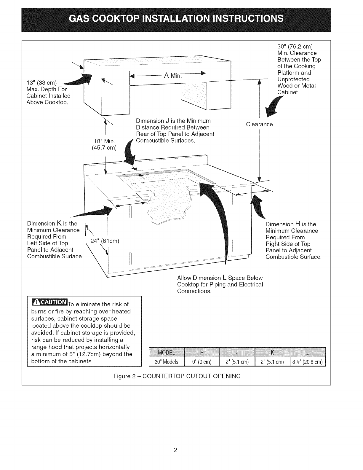
13" (33 cm)
Max. Depth For
Cabinet Installed
Above Cooktop.
30" (76.2 cm)
Min. Clearance
Between the Top
of the Cooking
Platform and
---------_-¢U nprot ected
Wood or Metal
binet
Dimension K is the
Minimum Clearance
Required From
Left Side of Top
Panel to Adjacent
Combustible Surface.
18" Min.
(45.7 cm)
24" _ cm)
Dimension J is the Minimum
Distance Required Between
Rear of Top Panel to Adjacent
Combustible Surfaces.
Allow Dimension L Space Below
Cooktop for Piping and Electrical
Connections.
Clearance
Dimension H is the
Minimum Clearance
Required From
Right Side of Top
Panel to Adjacent
Combustible Surface.
_J__To eliminate the risk of
burns or fire by reaching over heated
surfaces, cabinet storage space
located above the cooktop should be
avoided. If cabinet storage is provided,
risk can be reduced by installing a
range hood that projects horizontally
a minimum of 5" (12.7cm) beyond the
bottom of the cabinets.
Figure 2 - COUNTERTOP CUTOUT OPENING
[ 30"Models [ 0" (0cm) J. 2" (5.1cm) J. 2" (5.1cm) 81/8''(20.6cm)
2
important Notes to the Installer
1. Read all instructions contained in these installation
instructions before installing the cooktop.
2. Remove all packing material before connecting the
electrical supply to the cooktop.
3. Observe all governing codes and ordinances.
4. Be sure to leave these instructions with the
consumer.
5. Note: For operation at 2000 ft. elevations above see
level, appliance rating shall be reduced by 4 percent
for each additional 1000 ft.
Important Note to the Consumer
Keep these instructions with your Use and Care Guide
for future reference.
cabinets above the cooktop. Children could be
seriously burned climbing on the cooktop to reach
items.
To eliminate the need to reach over the surface
burners, cabinet storage space above the burners
should be avoided.
Adjust surface burner flame size so it does not
extend beyond the edge of the cooking utensil.
Excessive flame is hazardous.
Never use your cooktop for warming or heating
the room. Prolonged use of the cooktop without
adequate ventilation can be hazardous.
Do not store or use gasoline or other flammable
vapors and liquids near this or any other appliance.
Explosions or fires could result.
I PO NT SAFETY
I STR CTI
Installation of this cooktop must conform with local
codes or, in the absence of local codes, with the
National Fuel Gas Code ANSI Z223.1 / NFPA No.54
in the United States, or in Canada, with the Canadian
Fuel Gas Code, CAN/CGA B149 and CAN/CGA
B149.2.
This cooktop has been design certified by CSA
International. As with any appliance using gas and
generating heat, there are certain safety precautions
you should follow. You will find them in the Use and
Care Guide., read it carefully.
Be sure your cooktop is installed and grounded
properly by a qualified installer or service technician.
This cooktop must be electrically grounded in
accordance with local codes or, in their absence, with
the National Electrical Code ANSl/NFPA No. 70--
latest edition in the United States, or in Canada, with
the Canadian Electrical Code, CSA C22.1 Part 1.
The installation of appliances designed for
manufactured (mobile) home installation must
conform with Manufactured Home Construction and
Safety Standard Title 24CFR, Part 3280 [Formerly
the Federal Standard for Mobile Home Construction
and Safety, Title 24, HUD, (Part 280)] or when
such standard is not applicable the Standard for
Manufactured Home Installation 1982 (Manufactured
Home Sites, Communities and Set-Ups), ANSI
Z225.1/NFPA 501-A- latest edition, or with local
codes.
Do not store items of interest to children in the
The electrical power to the cooktop must
be shut off while gas line connections are being made.
Failure to do so could result in serious injury or death.
Safety Measures - Gas Surface Units
Your new cooktop has been tested to meet the most
rigid safety standards. You can feel confident while
using it but use these safety suggestions to help avoid
accidents that can cause injury to the user or damage
to the cooktop.
Note: All safety measures listed may apply to your
model.
Plug the unit into a 120-volt grounded outlet only.
Do not remove the grounding prong from the plug. If
in doubt about the grounding of the home electrical
system, it is the personal responsibility and obligation
of the owner to contact a qualified electrician and
have an ungrounded receptacle replaced by a
properly grounded three-prong wall receptacle, in
accordance with the National Electrical Code. Do not
use an extension cord with this unit.
Do not repair or replace any part of the unit unless
specifically recommended in this guide. Call a
qualified technician for all other servicing.
Clean only the parts of the cooktop as instructed in
the Use and Care Guide.
Be certain all packing materials are removed from
the unit before operating to prevent fire or smoke
damage, should the packing material ignite.
Ventilating Hoods
Clean ventilating hood frequently. Grease should not
be allowed to accumulate on hood or filter.
When flaming foods under the hood turn the fan off.
The fan, if operating, may spread the flame.
3
Safety on the Cooktop
Do not allow dry empty pans to heat on the cooktop
as this could ruin the pan and cause a fire hazard.
Do not use a wok on the cooking surface if it is
equipped with a round metal support placed over
the burner grate. This support acts as a heat trap
which may damage the burner grate, drip bowls and
burner head. It may also cause the burner to work
improperly and create a carbon monoxide hazard.
When lowering the cooktop be careful not to pinch
your fingers. Grasp sides of the top with fingertips
and lower into position.
Important: Please Read Before Continuing
This appliance and its individual shutoff valve must be
disconnected from the gas supply piping system during
any pressure testing of that system exceeding Y2psig.
This appliance must be isolated from the gas supply
pipping system by closing its individual manual shutoff
valve during any pressure testing of the gas supply
piping system equal to or less than Y2psig.
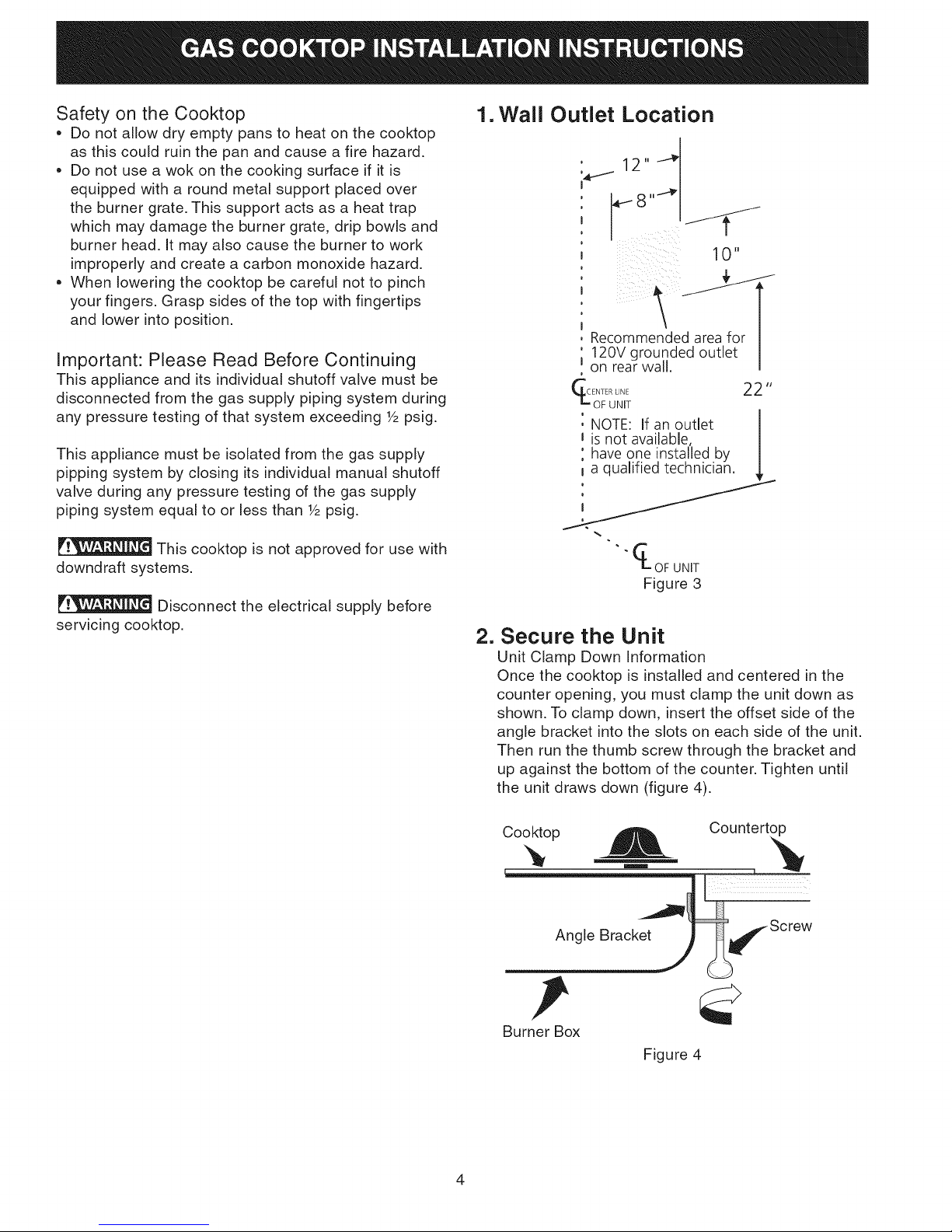
1. Wall Outlet Location
, 12._
i 10"
J Recommended area for /
120Vgrounded outlet |
Jon rear wall.
e
_ _FRuLN_ET 22 "
NOTE: Ifan outlet
is not available, I
have one installed by I
/
This cooktop is not approved for use with
downdraft systems.
Disconnect the electrical supply before
servicing cooktop.
_-OF UNIT
Figure3
2. Secure the Unit
Unit Clamp Down Information
Once the cooktop is installed and centered in the
counter opening, you must clamp the unit down as
shown. To clamp down, insert the offset side of the
angle bracket into the slots on each side of the unit.
Then run the thumb screw through the bracket and
up against the bottom of the counter. Tighten until
the unit draws down (figure 4).
Cooktop
m
Angle Bracket
Countertop
Burner Box
Figure 4
4

3. Provide an Adequate Gas Supply
The cooktop covered in these installation instructions
is designed to operate on natural gas at 4" (10.2cm)
of manifold pressure or on LP gas at 10" (25.4cm) of
manifold pressure.
Manual GAS FLOW Pressure
Shutoff Flare _'_ Flare Regulator
Valve Union Union 4,
A convertible pressure regulator is supplied with each
surface unit and MUST BE CONNECTED IN SERIES
between the supply line and the valve manifold
regardless of which type of gas is being used.
The convertible regulator for the surface units must be
located and turned in such manner to allow for easy
access to the convertible feature.
For proper operation, the maximum inlet pressure to
the regulator must not exceed 14" (35.6cm) of water
column (W.C.) pressure for both LP and Natural Gas.
For checking the regulator, the inlet pressure must
be at least 1" (2.5cm) (or 2.5 kPa) greater than the
regulator manifold pressure setting. If the regulator
is set for 4" (10.2cm) of manifold pressure, the inlet
pressure must be at least 5"(12.7cm). If the regulator is
set for 10" (25.4cm), the inlet pressure must be at least
11" (27.9cm).
The gas supply line to the cooktops should be W'
(1.3cm) or 3A"(1.9cm) pipe.
4. Connection to gas
IMPORTANT: Remove all packing material and
literature from cooktop before connecting gas and
electrical supply to the appliance.
_qJ_ Nip_Ple Flexible
Off Connector
All connections must be wrench-tightened
Figure 5
Assemble the flexible connector from the gas supply
pipe to the pressure regulator in the following order:
1. manual shutoff valve
2. 1/2" nipple
3. 1/2" flare union adapter
4. flexible connector
5. 1/2" flare union adapter
6. 1/2" nipple
7. pressure regulator
Use pipe-joint compound made for use with Natural
and LP/Propane gas to seal all gas connections. If
flexible connectors are used, be certain connectors are
not kinked.
The supply line must be equipped with an approved
manual shutoff valve. This valve should be located
in the same room as the cooktop and should be in a
location that allows ease of opening and closing. Do
not block access to the shutoff valve. The valve is for
turning on or shutting off gas to the appliance.
Access
Cap
Seal all openings in the wall behind the cooktop and
in the floor under the cooktop after gas supply line is
installed.
Install Pressure Regulator
Install the pressure regulator with the arrow on the
regulator pointing up toward the unit in a position
where you can reach the access cap.
Do not make the connection too tight.
The regulator is die cast. Overtightening may crack the
regulator resulting in a gas leak and possible fire or
explosion.
Shutoff Valve =
Open position
Figure 6
Once regulator is in place, open the shutoff valve in
the gas supply line. Wait a few minutes for gas to move
through the gas line.
Check for leaks. After connecting cooktop gas, check
system for leaks with a manometer. If a manometer is
not available, turn on the gas supply and use a liquid
leak detector (or soap and water) at all joints and
connections to check for leaks.
5

Donotuseflametocheckforleaksfrom
gasconnections.Checkingforleakswithaflamemay
resultinafireorexplosion.
Tightenallconnectionsif necessarytopreventgas
leakageinthecooktoporsupplyline.
Checkalignmentofcontrolknobvalvesafter
connectingthecooktopto thegassupplytobe
surethecooktopmanifoldpipehasnotmoved.A
misalignmentcouldcausethevalvestemstorubon
thecontrolpanel,resultingina gasleakatthevalve.
Disconnectthecooktopanditsindividualmanual
shutoffvalvefromthegassupplypipingsystemduring
anypressuretestingofthatsystematatestpressure
greaterthanY2psig (3.5 Kpa or 14" water column).
Isolate the cooktop from the gas supply piping system
by closing its individual manual shutoff valve during
any pressure testing of the gas supply piping system at
a test pressures equal to or less than Y2psig (3.5 Kpa
or 14" water column).
5. LP/Propane Gas Conversion
A. Pressure Regulator Conversion
Note: = Do not remove the Pressure Regulator.
If in doubt about the pressure at the manifold,
use a manometer. The inlet pressure on the
regulator must be at least 1" W.C. higher than
the outlet pressure. Inlet pressure on the
regulator must never exceed 14" W.C.
Cap position
NAT
Figure 8
,
Turn the plug over so that the nib on the end of the
cap faces upward and re-insert into the cap (Figure
9). Rotate the plug 90° degrees in either direction to
lock it into the cap (Figure 10).
Figure 10Figure 9
,
Reinstall the cap and plug securely onto the
regulator (Figure 11).
Cap
for LP
,
Unscrew the hex shaped cap and turn it over to
access the conversion plug inside the cap (Figure 7).
f
J
\._oj)
Figure 7
,
Rotate the plug 90° degrees in either direction to
align the tabs on the plug with the notches in the
cap (Figure 8).
Figure 11
B=
Burner Valves Conversion
(see figure 12 and 13)
Figure 12
6
 Loading...