

Sears Gamefisher 298.585130 Owner's Manual

MODELNO.
298.585130
• owner's
responsibility
• maintenance
,_operation
• trouble
shooting
,= replacement
paris
Publication No.
970-35118-203
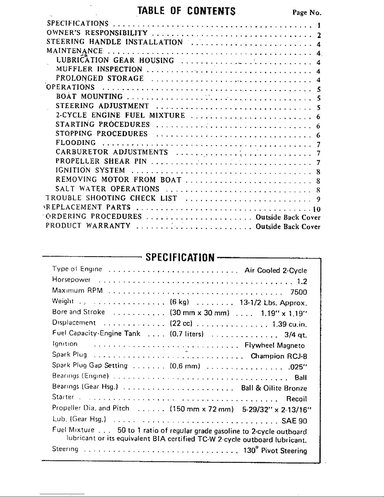
TABLE OF CONTENTS Pag,,No.
SPECIFICATIONS ......................................... I
OWNER'S RESPONSIBILITY ................................. 2
STEERING HANDLE INSTALLATION 4
MAINTENANCE , ......................................... 4
LUBRIC'_kTION GEAR HOUSING ............... ,............ 4
MUFFLER INSPECTION .......... ........................ 4
PROLONGED STORAGE .................................. 4
'OPERATIONS ............................................ S
BOAT MOUNTING ................ . ..................... 5
STEERING ADJUSTMENT ................................ 5
2-CYCLE ENGINE FUEL MIXTURE ......................... 6
STARTING PROCEDURES - 6
STOPPING PROCEDURES ........... ..................... 6
FLOODING ........................................... 7
CARBURETOR ADJUSTMENTS " 7
PROPELLER SHEAR PIN .......... • ...... . ................ 7
IGNITION SYSTEM ..................................... 8
REMOVING MOTOR FROM BOAT .......................... 8
SALT WATER OPERATIONS .............................. 8
TROUBLE SHOOTING CHECK LIST .......................... 9
_R EPLACEMENT PARTS .................................... I0
• ORDERING PROCEDURES .... ; ................. Outside Back Cover
PRODUCT WARRANTY - Outside Back Cover
SPECIFICATION
Type of Engine ........................... Air Cooled 2-Cycte
Horsepower ........................................ 1.2
Maximum RPM .................................... 7500
Weight . ,................ (6 kg) ........ 13-1/2 Lbs. Approx.
Bore and Stroke ........... (30 mm x 30 mm) .... 1.19" x t.19"
D_splacement ............. (22 cc) ............... 1.39 cu.in.
Fuel Capacity-Engine Tank .... (0.7 liters) .............. 3/4 qt.
Igmtlon .............................. Flywheel Magneto
Spark Plug ................... "_ ........... Champion RCJ-8
Spark Plug Gap Setting ....... (0.6 ram) ................. 025"
Bearings (Engine) .................................... Ball
Bearings (Gear Hsg.) ....................... Ball & Oilite Bronze
Staster Recoil
Propeller Dia. and Pitch ...... (150 mm x 72 ram) 5-29/32" x 2-13/16"
Lub. (Gear Hsg.) ................................. SAE 90
Fuel M_xture . . . 50 to 1 ratio of regular grade gasoline to 2-cycle outboard
lubricant or its equivalent BIA certified TC-W 2-cycte outboard lubricant.
Steering ................................ 130 ° Pivot Steering
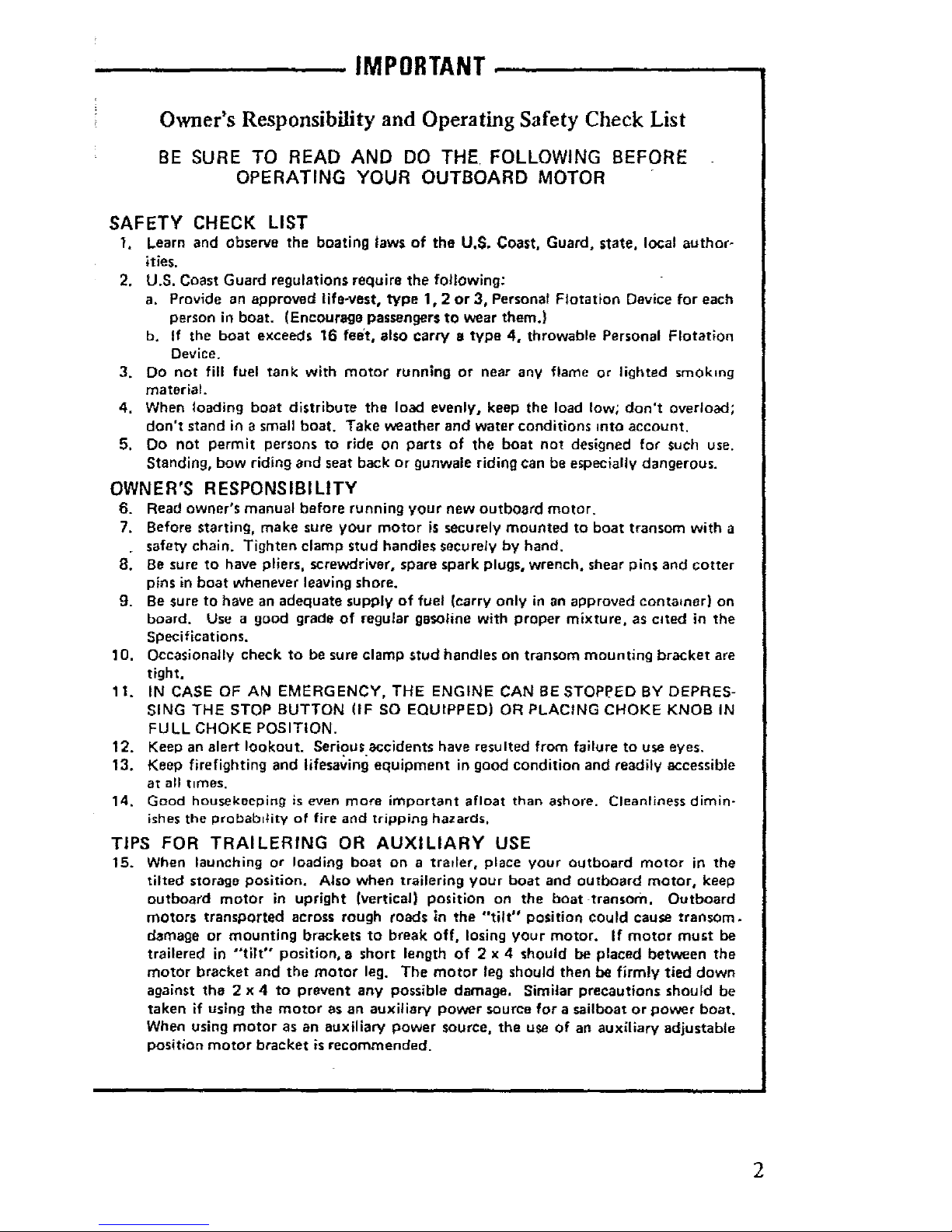
IMPORTANT
Owner's Responsibility and Operating Safety Check List
BE SURE TO READ AND DO THE. FOLLOWING BEFORE
OPERATING YOUR OUTBOARD MOTOR
SAFETY CHECK LIST
I. Learn and observe the boating Jaws of the U.S, Coast, Guard, state, local author-
ities.
2. U,S. Coast Guard regulations require the following:
a. Provide an approved life-vest, type 1,2 or 3, Personal Flotation Device for each
person in boat. (Encourage passengers to wear them.)
b, If the boat exceeds 16 feat, also carry e type 4, throwable Personal Flotation
Device.
3. Do not fill fuel tank with motor running or near any flame or lighted smoking
material.
4. When loading boat distribute the load evenly, keep the load low; don't overload;
don't stand in a small boat. Take weather and water conditions into account.
5. Do not permit persons to ride on parts of the boat not designed for such use.
Standing, bow riding and seat back or gunwale riding can be especially dangerous.
OWNER'S RESPONSIBILITY
6. Read owner's manual before running your new outboard motor.
7. Before starting, make sure your motor is securely mounted to boat transom with a
. safety chain. Tighten clamp stud handles securely by hand.
8. Be sure to have pliers, screwdriver, spare spark plugs, wrench, shear pins and cotter
pins in boat whenever leaving shore.
g. Be sure to have an adequate supply of fuel (carry only in an approved container) on
b_ard, Use a good grade of regular gasoline with proper mixture, as cdted in the
SpeciHcations.
10. Occasionally check to be sure clamp stud handles on transom mounting bracket are
tight.
11. IN CASE OF AN EMERGENCY, THE ENGINE CAN BE STOPPED BY DEPRES-
SING THE STOP BUTTON (IF SO EQUIPPED) OR PLACING CHOKE KNOB IN
FULL CHOKE POSITION.
12. Keep an alert lookout. Serious accidents have resulted from failure to u_e eyes,
13. Keep firefighting and lifesaving equipment in good condition and readily accessible
at all t_mes.
14, Good housekeeping is even more important afloat than ashore. Cleanliness dimin-
ishes the probab)tity of fire and tripping hazards,
TIPS FOR TRAILERING OR AUXILIARY USE
15. When launching or loading boat on a trailer, place your outboard motor in the
tilted storage position. Also when trailering your boat and outboard motor, keep
outboard motor in upright (vertical) position on the boat transom. Outboard
motors transported across rough roads in the "tilt" position could cause transom.
damage or mounting brackets to break off, losing your motor. If motor must be
trailered in "tilt" position, a short length of 2 x 4 should be placed between the
motor bracket and the motor leg. The motor leg should then be firmly tied down
against the 2 x 4 to prevent any possible damage, Similar precautions should be
taken if using the motor as an auxiliary power source for a sailboat or power boat.
When using motor as an auxiliary power source, the use of an auxiliary adjustable
position motor bracket is recommended.
2
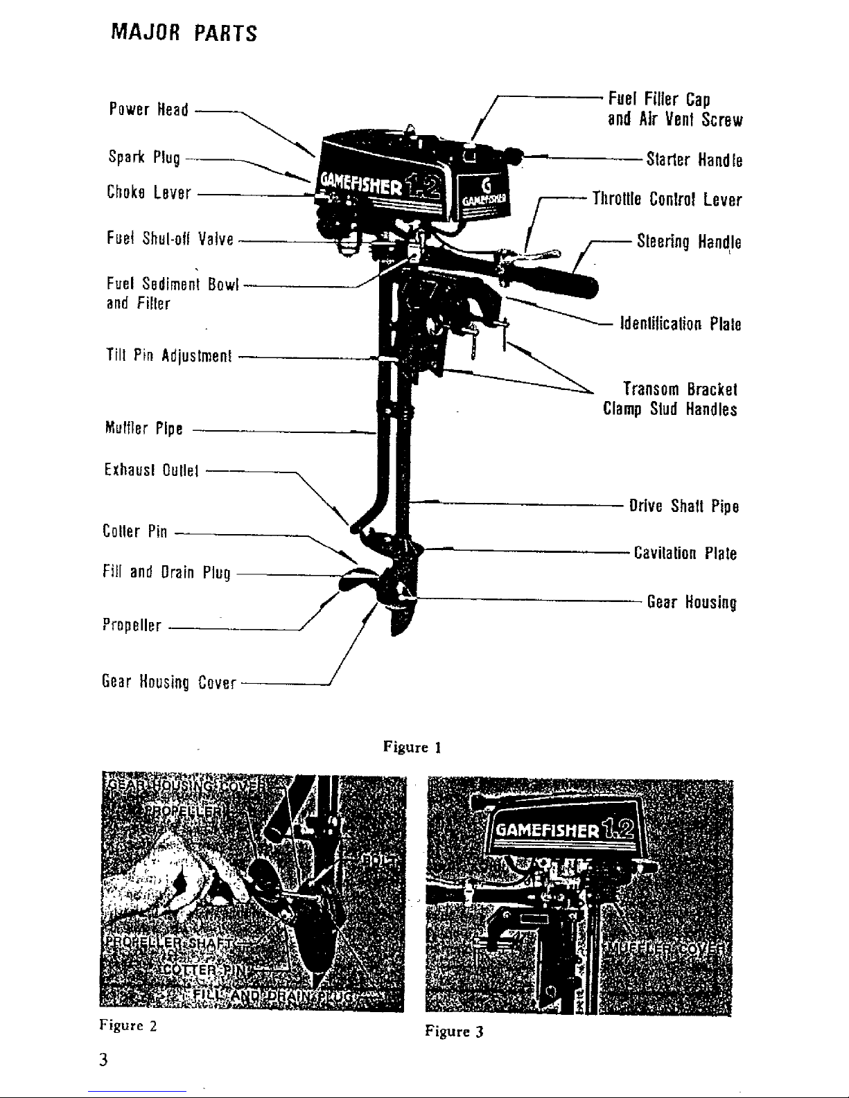
MAJOR PARTS
PowerHeed
SparkPlug
FuelShul-oflVatve
FuelSedimentBow[
andFilter
Tilt Pin Adjustment
MufflerPipe
ExheuslOullel
CoUerPin
Fill andDrainPlug
\
Propeller
/
-Fuel Filler Cap
andAirVenl Screw
Slarter Handle
Throllle ConlrolLever
SleetingHandle
IdenlilicalionPlale
TransomBracket
ClampSludHandles
Drive Shall Pipe
CavilaUonPlate
GearHousing
Figure 2
Figure 1
3
Figure 3
INTENANCE
! FEATURE INFORMATION
This outboard motor has special design
features as shown in Figure 1;
Your selection of our Marine Products will
!provide you with many hours of enjoyable
iboating. To assure your conll01e_te satisfac-
i_ion on the investment you have just made,
iwe ask you to read this manual thoroughly
before going afloat. Acquaint yourself with
]the particular areas of operation on your
ioutboard motor as you read the step-by-step
_procedures. Keep _n"mind maximum per-
formance is achieved only when the owner
or operator is completely familiar with the
operating instructions.
Periodic servicing will be required. It is
recommended that you consult your Sears
Service Center when service is necessary.
We wilt be happy to extend our facilities
and assure prompt service.
STEERING HANDLE INSTALLATION
move snap pin and washer 5 from, .ste.ering
dle, screw handle mounting bolt in joint
e holder and stop steenng handle, Then push
;_ove at tip of steering handle against handle
pper.
it washer 5 in over handle mounting bolt and
iert snap loin.
LUBRICATION--GEAR HOUSING
The Gear Housing has been pre-lubricated at
the factory; however, the grease level should
be checked as follows using SAE 90 out-
board motor grease. (See Figure 2).
(1) Prior to initial operation,
(2) After first four (4) hours of use.
(3) Recheck after every fifty (50) hours
running time.
(4) Replace with new lubricant at the end
of your outboard motor season. This
is =mportant. as it removes any water
from the gear housing and prevents
I
[ possible corrosion to internal parts.
! To Check, Drain or Fill gear housing, follow
these steps:
(1) Position outboard motor upright.
(2) Remove drain plug and washer, then
insert nozzle of gear lubricant tube
into hole.
(3) Squeeze tube untii lubricant is forced
out around tube.
(4) Replace plug and washe(. Be sure piug
is tightened securely.
(5) To achieve complete drainage of-_ubrJ-
cant, remove cotter pin, propeller and
shear pin from propeller shaft, also,
gear housing cover by unscrewing 2
bolts.
C°
(6) When lubricant has completely drained,
reptape parts and refill gear housing
using filling procedure above,
For best results, lubricate propeller shaft
with lithium grease every 30 to 60 days.
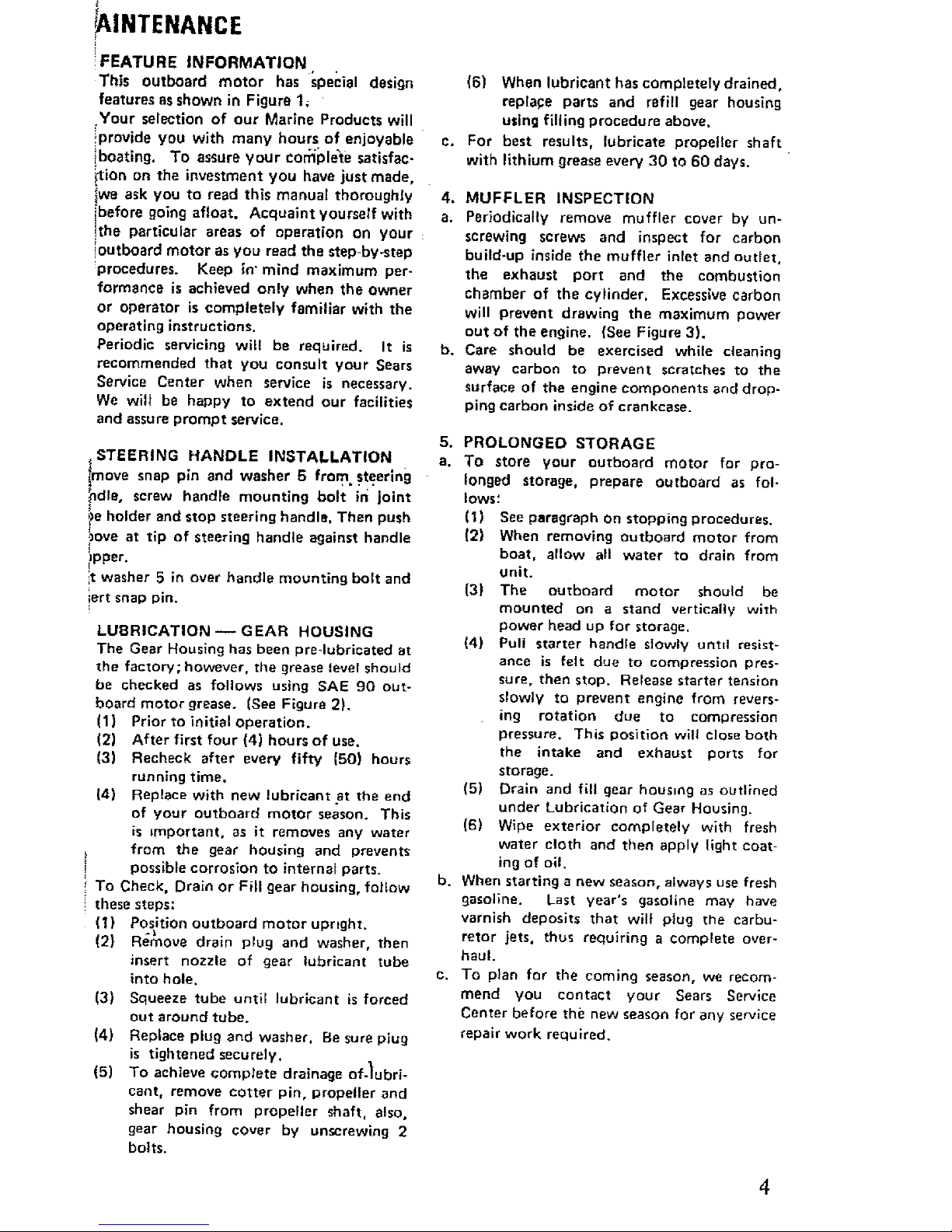
4. MUFFLER INSPECTION
a. Perlod_calI¥ remove muffler cover by un-
screwing screws and inspect for carbon
build-up inside the muffler inlet and outlet,
the exhaust port end the combustion
chamber of the cylinder, Excessive carbon
will prevent drawing the maximum power
ou't of the engine. {See Figure 3).
b. Care should be exercised while cleaning
away carbon to prevent scratches to the
surface of the engine components and drop-
ping carbon inside of crankcase.
5. PROLONGED STORAGE
a. To store your outboard motor for pro-
longed storage, prepare outboard as fol-
lows;
(I) See paragraph on stopping procedures.
(2) When removing outboard motor from
boat, allow all water to drain from
unit.
(3) The outboard motor should be
mounled on a stand vertically with
power head up for storage.
(4) Pull starter handle slowly untd resist-
ance is felt due to compression pres-
sure, then stop. Release starter tension
slowly to prevent engine from revers-
ing rotation due to comoression
pressure. This position will close both
the intake and exhaust ports for
storage.
(5) Drain and fill gear housing as outlined
under Lubrication of Gear Housing.
(6) Wipe exterior completely with fresh
water cloth and then apply light coat-
ing of oil.
b. When starting a new season, always use fresh
gasoline. Last year's gasoline may have
varnish deposits that wil} plug the carbu-
retor jets. thus requiring a complete over-
haul.
c. To plan for the coming season, we recom-
mend Vou contact your Sears Service
Center before the new season for any service
repair work required.
JPI'HA[ IL1N
,. BOAT MOUNTING
Mount the motor on the center of the boat
transom (stern). (See Ftgure4).
CAUTION
Hand t_ghten clamp bracket clamp stud
handles stmultaneously. Do not use a
wrench or any other device that would
cause damage to brackets. Occasionally
check to be sure lamp stud bandies on
transom mounting bracket are tight.
(See Figure 5)
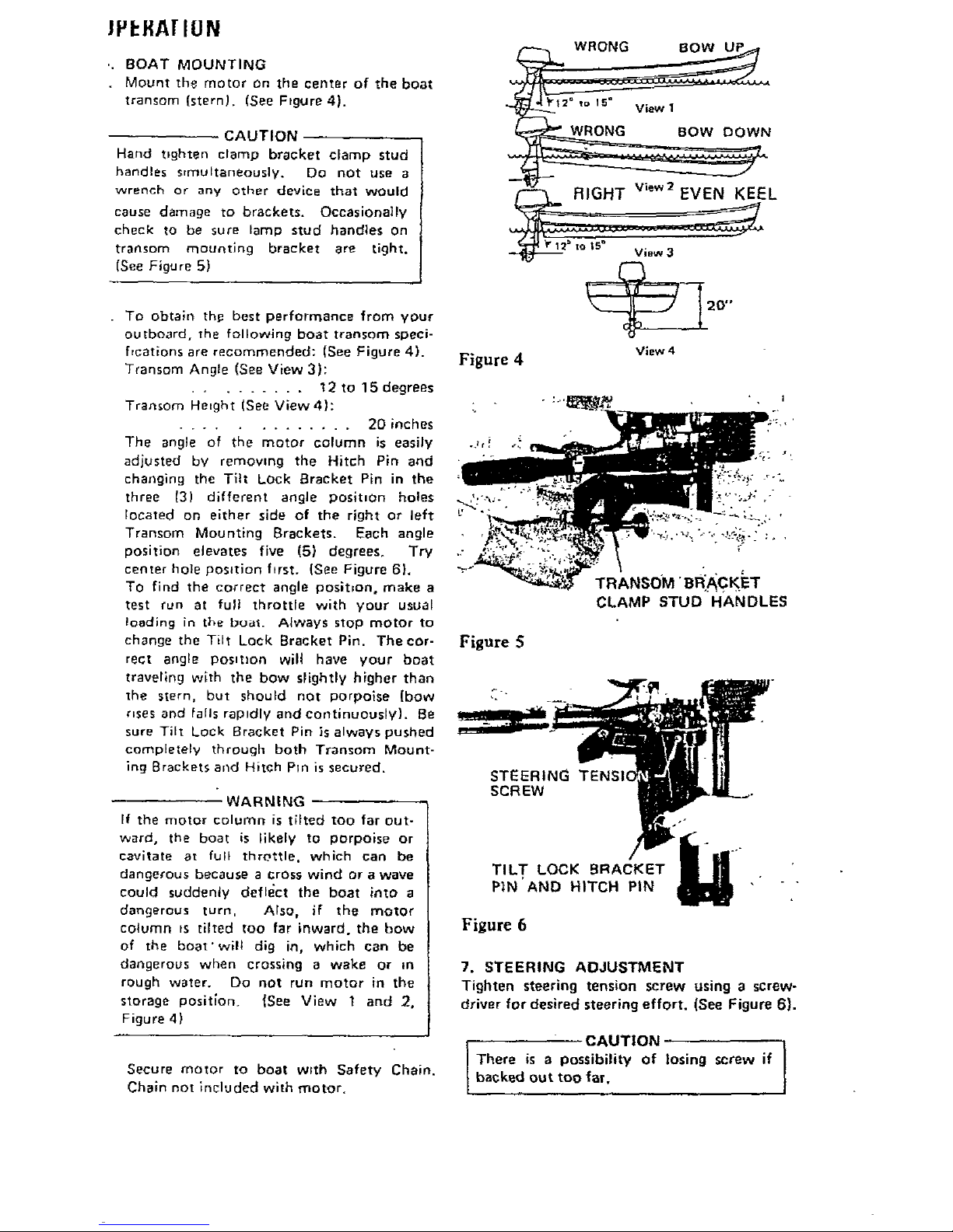
To obtain thp best performance from your
outboard, the following boat transom speci-
frcations are recommended: (See Figure 4).
Transom Angle (See View 3):
......... t 2 to 15 degrees
Transom Height (See View4):
............. 20 inches
The angle of the motor column is easily
adjusted bv removing the Hitch Pin and
changing the Tilt Lock Bracket Pin in the
three t3) different angle positnOn holes
located on either side of the right or left
Transom Mounting Brackets. Each angle
position elevates five (5) degrees. Try
center hole position f_rst. (See Figure 6},
TO find the correct angle poslt=on, make a
test run at full throttle with your usual
loading in the boat. Always stop motor to
change the Tilt Lock Bracket Pin. The cor-
rect angle Posnt_on wil! have your boat
traveling with the bow slightly higher than
the stern, but should not porpoise [bow
r=ses and falls rapidly and continuously). Be
sure Tilt Lock Bracket Pin is always pushed
completely through both Transom Mount-
ing Brackets and Hitch Pm is secured.
WARNING
If the motor column is tilted too far out-
ward, the boat is likely to porpoise or
eavitate at full throttle, which can be
dangerous because a cross wind or a wave
could suddenly deflect the boat into a
dangerous turn, Also, if the motor
column us tilted too far inward, the bow
of the boat'will dig in, which can be
dangerous when crossing a wake or tn
rough water. Do not run motor in the
storage position. {Sea View 1 and 2,
Figure 4)
Secure motor to boat wrtb Safety Chain.
Chain not included with motor.
Figure 4
.... ! ._
__ 20°"
View 4
Figure 5;
TRANSOM' 13RI._€I_ET
CLAMP STUD HANDLES
STEERING TENSI(
SCREW
TIL T LOCK BRACKET
PIN AND HITCH PIN
Figure 6
7. STEERING ADJUSTMENT
Tighten steering tension screw using a screw-
driver for desired steering effort, (See Figure 6).
I CAUTION
There is a possibility of losing screw if
backed out too far,
OPERATION
8. 2-CYCLE ENGINE FUEL MIXTURE
Use a good grade of regular gasoline. (See mix-
ing table below,)
CAUTION
Always usa BIA certified TC-W oil in the
50:1 ratio, Failure to do =0 may result tn
excessive spark plug fouling, piston
scoring, or bearing failure. Do not under
any circumstances, ur_ muttigrade, such as
10W-30, or other automobile oils,
If BIA certified oil is not available, use
an SAE 30 or 40 2,<:ycle or outboard oil.
We reserve the right to refuse warranty on
parts which are damaged when using
improper fuels or fubrldants.
WARNING
Gasoline is highly flammable. Always mix
in wefl ventiJated area, Do not fill tank
with motor running, nor near any flame
or while smoking. Be sure vent screWs
and filler caps on tanks are finger tighte-
ned when transporting gasoline in the
trunk of your automobile to prevent
explosion.
FUEL
MIXING
TABLE
50" 1
MIXTURE
U.S. Measure
Regular Amount of 0;I
Gasoline to be added "
in Gallons In Pints In Oz
1 0.16 2.6
3 0.48 7.7
5 0,80 12.8
6 0.96 15.4
Metric Measure
Regular
Gasotina
In Liters
1
5
10
2o
Amount of oil
to be added
In Liters
0.02
0.10
0.20
0.40
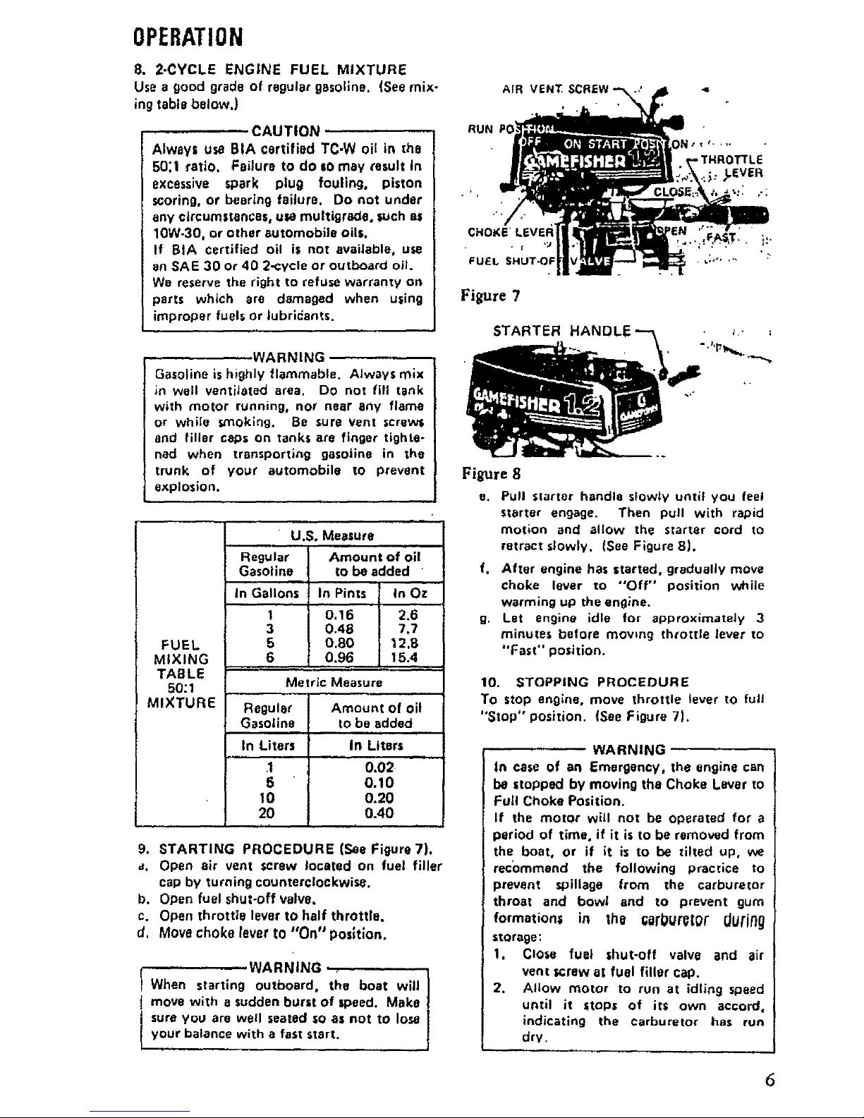
9. STARTING PROCEDURE (See Figure 7).
a, Open air vent screw located on fuel filler
cap by turning counterclockwise,
b. Open fuel shut-off valve,
c. Open throttle lever to half throttle.
d, Move choke lever to "On" posfflon.
WARNING ,
When starting outboard, the boat will
move with a sudden burst of speed, Make
sure you are well seated sO as not to lose
your balance with a fast start.
AIR VENT•
RUN P0
Figure 7
STARTER HANDLE
Flsure 8
e. Pull Slartor handle slowly until you feel
starter engage. Then pull with rapid
motion and allow the starter cord to
retract slowly. (See Figure 8).
f. After engine has started, gradually move
choke lever to "Off" position v_,_ile
warming up the engine.
g. Let engine idle for approxlmately 3
minutes before mowng throttle lever to
"Fast" position.
10, STOPPING PROCEDURE
To stop engine, move throttle lever to full
"Stop" position. {See Figure 7).
WARNING
In case of an Emergency, the engine can
be stopped by moving the Choke Laver to
Full Choke Position.
If the motor will not be operated for a
period of time. if it is to be removed from
the boat, or if it is to be tilted up, we
rec'ommend the following practice to
prevent spillage from the carburetor
throat and bowl and to prevent gum
formation= in the =orburQtgrUuring
storage:
I, Close fuel shut-off valve and air
vent _crew at fuel filler cap,
2. Allow motor to run at idling speed
until it stops of its own accord,
indicating the carburetor has run
dry,
 Loading...