

Sears Free Spirit 298.488531 Owner's Manual
IIIII I
SPORTS CENTER
MODELNO.
298.488531
• contents
• Installation
• operation
• adjustment
• maintenance
• replacement parts
p
OWNER,SMANUAL
: II IIII] I
=L
L •
Publication No. 970-36151-202
E
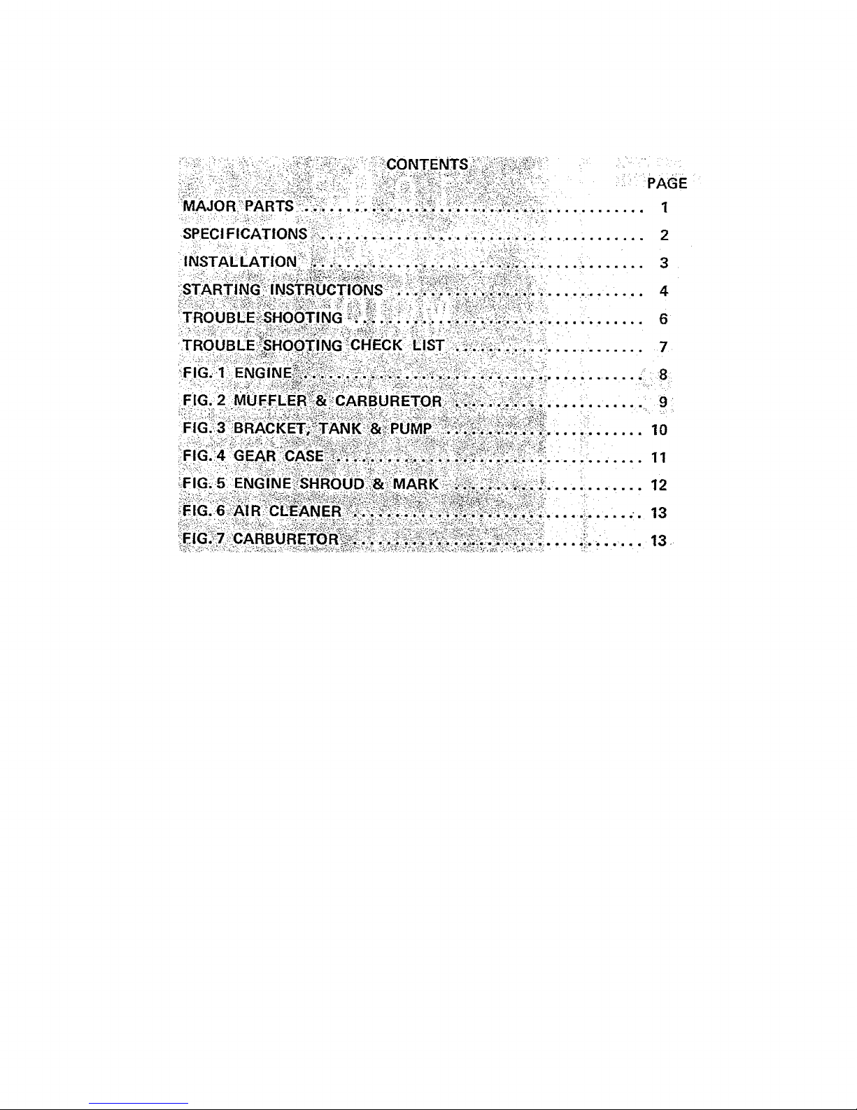
M .............. 1
SPECJFi_oNs:'_!i_.:_:;:_-...:..:i..........!!;_:.,_;;i_!-:.:._:i.;::............ 2
. = ,-. ,.,o . . . ° . , = . o . o . = = o
°°°°=°°°°6. 6
°.==°.o.°°. 9
lO
...... . ...... 11
12
.... _...... ;. 13
.... _........ 13
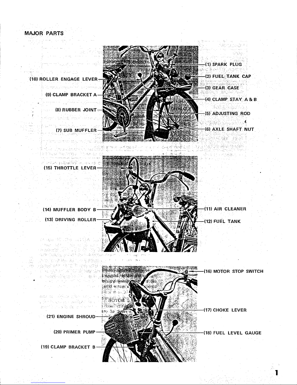
MAJOR PARTS
. =
(10) ROLLER ENGAGE
(9) CLAMP BRA(
(8) RUBBER
" (7| SUB MUFFLER
(15) THROTTLE
(14) MUFFLER BODY
(13) DRIVING
o • -o
AIR :CLEANER
12) FUEL TANK
16) MOTOR STOP SWITCH
(21) ENGINE
(17) CHOKE LEVER
(20) PRIMER
(18) FUEL LEVEL GAUGE
(19) CLAMP BRACKET
• _ ••i• i •• _,•_ii¸
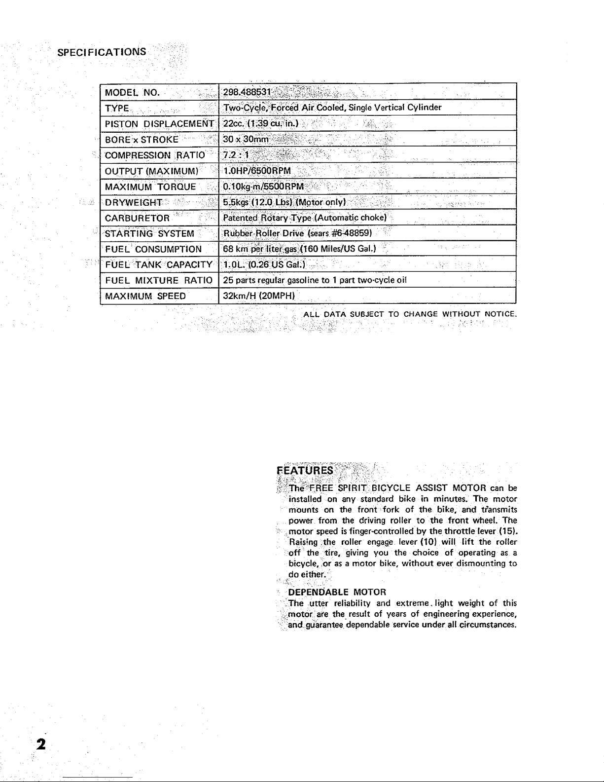
SPECl FICATIONS
MODEL NO. _ ;,.i::,.
TYPE ; : : i::_i:
PISTON DISPLACEMENT
'COMPRESSION :,RATIO
OUTPUT (MA XIMUM) !i
., , . , ...........
DRMWEIGHT-:--_":_ .....-::_/:i!i::5!5k_s!('.12:0:l_b_):[i(MotoronlYl '";::;!(::.:'i:_:4:-/. "............
CARBURETOR :_'?' [L: ' iPaten'te_J_;R_iary:Typeti(Auiomatic Choke}'
STAi_i:iNG sYSTEM : Ru'bb_#-Roiier Dri_te (_ears #648859) :;_:
FUEL _CONSUMPTION :68 I<_P_r:iiitei_igasli;(i60 Mites/US Gal,) ":i ....
FOEI_ :TANK : CAPACITY" !1;OL,::(0!2B:LjS Gai:il : ;_
FUEL MIXTURE RATIO 25 parts regutar gasoline to 1 part two-cYcle oil
MAXIMUM SPEED 32km/H (20MPH) :
ALL DATA SUBJECT TO CHANGE W:[THOUT NOTICE.
PtRIT-i6 c¥c,EASSISTMOTOR be
:'installed on any standard bike in minutes.' The motor
mounts on the fr0nt fork of the bike,:and transmits
power from the driving roller to the front wheel. The
!_ _motor speed isfinger-controlled by the throttle lever (15).
Rais!ng the roller engage lever (10} wil! lift the roller
off _the tir e, giving you the choice of operating as a
:bicycle,'.or as a motor bike, without ever dismounting to
do eitfter: _
DEPENDABLE MOTOR
:•liThe utter reliability and extreme.light weight of this
;i.motor:ate the result of years of engineering experience,
?ii_andguarantee dependable service under all circumstances.
2
J:
HANDLING
Because of the ease of installation, and simplified con-
trois, the motor can be used on every type of bike, from
a ten-speed racer to a three-wheeled adult tricycle.
ECONOMICAL _:"-
The motor runs up to 160 miles_per gallon (MPG) at an
averagecruising speed. . •
GREAT PERFORMANCE... PEDAL,- OR POWER
Since the moto_mounts on-yOur_own bike, a bike suited
to your needs, you have the best of two worlds. Motor
off, your. bike performs as_welt as it always did. Motor
on, you've added a wonderful new dimension to cycling,
without sacrifice.
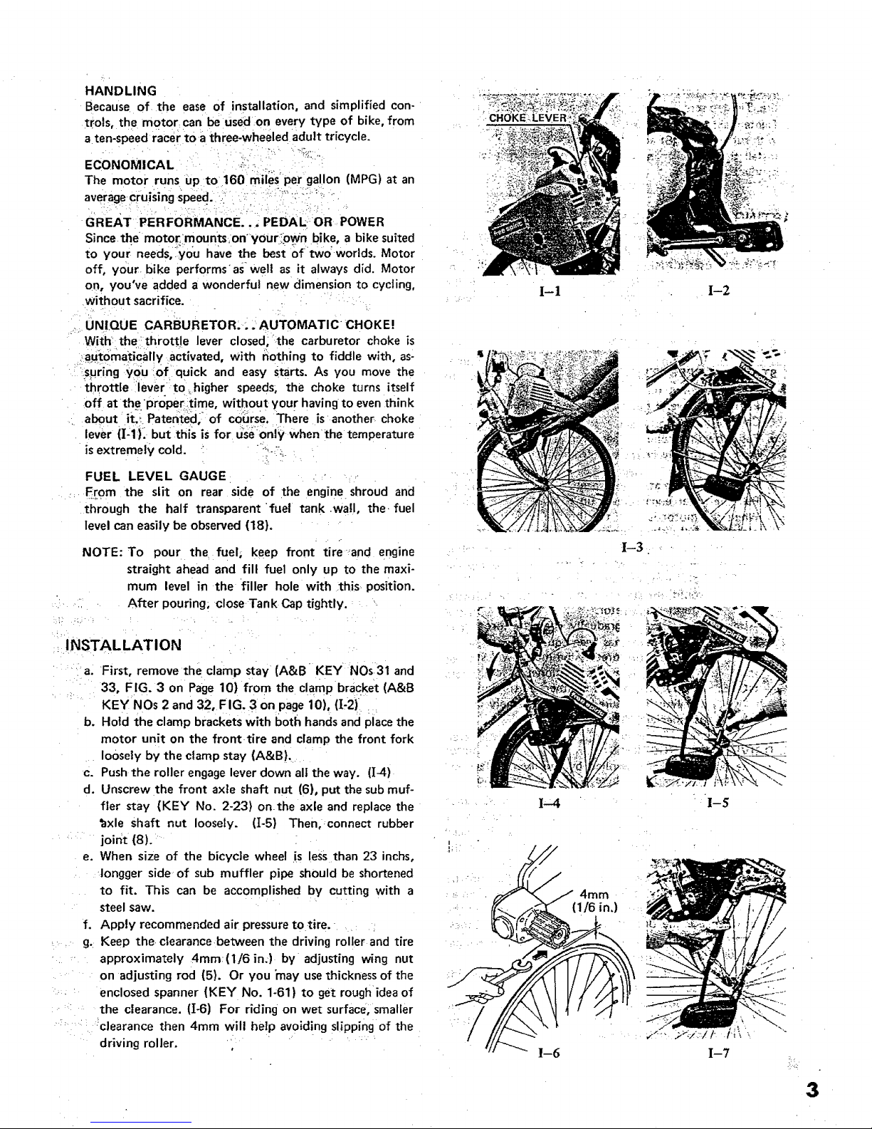
UNIQUE CARBURETOR:.. AUTOMATIC •:CHOKE!
With=the: throttle lever closed, the carburetor choke is
._aut0matically activated, with nothing to fiddle with, as-
spring you of quick and easy starts. As you move the
throttle lever to.higher speeds; the choke turns itself
off at the "proper.time, without your having to even think
about it_i Patented; _of co_rse, There is=another choke
lever (][:1:).-but this is for useonly when the temperature
is extremely cold. " _:-j:_
FUEL LEVEL GAUGE
F:rom the slit on rear side of the engine shroud and
through the half transparent fuel tank •wall, the. fuel
level can easily be observed (18).
NOTE: To pour the fuel, keep front tire=and engine
straight ahead and fill fuel only up to the maxi-
mum level in the filler hole with this. position.
After pouring; close Tank Cap tightly.
I-!
I-3
INSTALLATION
a. First, remove the clamp stay (A&B KEY NOs31 and
33° FIG. 3 on Page 10) from the clamp bracket (A&B
KEY NOs 2 and 32, FIG. 3 on page 10), ([-2)
b. Hold the clamp brackets with both handsand place the
motor unit on the front tire and clamp the front fork
loosely by the clamp stay (A&B).
c. Push the roller engagelever down all the way. (][-4)
d. Unscrew the front axle shaft nut (6), put the sub muf-
tier stay (KEY No. 2-23) onthe axle and replace the
bxle Shaft nut loosely. (I-5) Then, connect rubber
joint (8).
e. When size of the bicycle wheel is !ess than 23 inchs,
Iongger side of sub muffler pipe should be shortened
to fit. This can be accomplished by cutting with a
steel saw.
f. Apply recommended air pressure to tire. ;
g. Keep the clearance between the driving roller and tire
approximately 4mm(1/6 inJ by adjusting wing nut
on adjusting rod (5). Or you "may use thickness of the
• enclosed spanner (KEY No. 1-61) to get rough idea of
the clearance. (I-6) For riding on wet surface, smaller
:_ : _clearance then 4mm will help avoiding slipping of the
driving roller. " ....
3
 Loading...