

Page 1
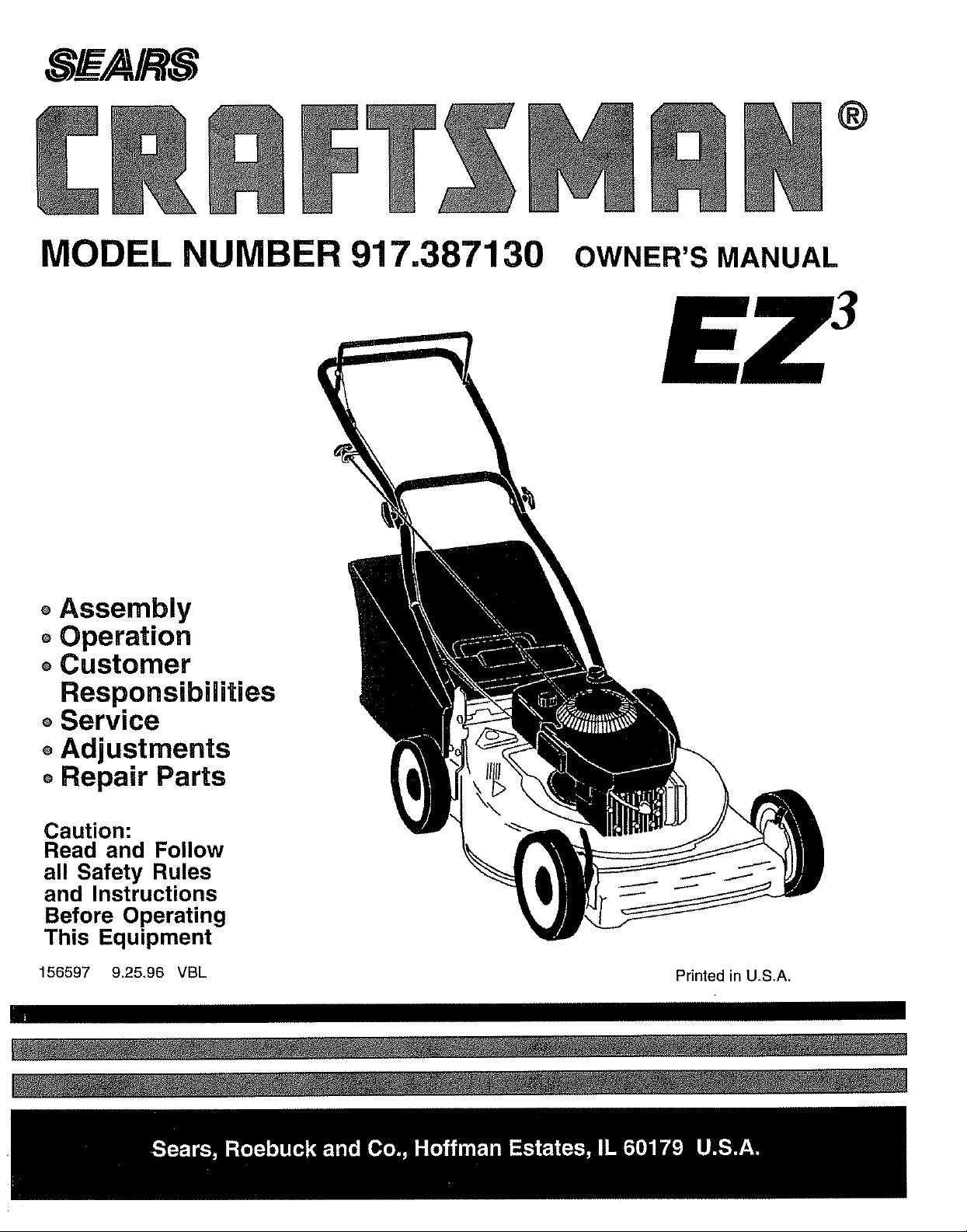
MODEL NUMBER 917.387130 OWNER'SMANUAL
oAssembly
oOperation
oCustomer
Responsibilities
oService
oAdjustments
oRepair Parts
Caution:
Read and Follow
all Safety Rules
and Instructions
Before Operating
This Equipment
156597 9.25,96 VBL
Printed in U.S,A,
Page 2
A SAFETY RULES A
IMPORTANT: THIS CUTTING MACHINE IS CAPABLE OF AMPUTATING HANDS AND FEET AND THROWING OBJECTS.
FAILURE TO OBSERVE THE FOLLOWING SAFETY INSTRUCTIONS COULD RESULT IN SERIOUS INJURY OR DEATH.
SAFETY STANDARDS REQUIRE OPERATOR PRESENCE CONTROLS TO MINIMIZE THE RISK OF INJURY. YOUR UNIT IS
EQUIPPED WITH SUCH CONTROLS. DO NOT ATTEMPT TO DEFEAT THE FUNCTION OF THE OPERATOR PRESENCE
CONTROLS UNDER ANY CIRCUMSTANCES
Safe Operation Practices for Walk-Behind Mowers
TRAINING:
Read thisoperator's manual carefully Become familiar with
the controls arrd know how to operate your mower properly
Learn how to quickly stop mower.
Do not allow children touse your mower. Never allow adults
to use mower without proper instructions
Keep the area of operation clear of all persons, especially
small children and pets+
Use mower only as the manufacturer intended and as de-
scribed in this manual
Do not operate mower ifit has been dropped or damaged in
any manner. Always have damage repaired before using
your mower,
Do notuse accessory attachments thatare not recommended
by the manufacturer Use of such gttachments may be
hazardous.
The blade turns when the engine is running.
PREPARATION:
Always thoroughly check the area to be mowed and clear it of
all stones, sticks, wires, bones, and other foreign objects.
These objects will be thrown by the blade and can cause
severe injury
D
Always wear safety glasses or eye shields when starting and
while using your mower,
Dress properly. Do not operate mower when barefoot or
wearing open sandals Wear only solid shoes with good
traction when mowing
Check fuel tank before starting engine. Do not fill gas tank
indoors, when the engine is running orwhen the engine is hot
Allow the engine to cool for several minutes before filling the
gas tank, Clean off any spilled gasoline before starting the
engine.
Always make wheel height adjustments before starting your
mower. Never attempt to do this while the engine is running.
Mow only in daylight or good artificial light
OPERATION:
Keep your eyes and mind on your mower and the area being
cut Do not let other interests distract you
Do not mow wet or slippery grass Never run while operating
your mower. Always be sure of your footing -keep a firm hold
on the frandles and walk+
• Do not put hands or feet near or under rotating parts. Keep
clear of the discharge opening at all times.
• Always stop the engine whenever you leave or are not using
your mower, or before crossing driveways, walks, roads, and
any gravel-covered areas,
• Never direct discharge of material toward bystanders nor
allow anyone near the mower while you are operating it.
• Before cleaning, inspecting, or repairing your mower, stop the
engine and make absolutely sure the blade and all moving
parts have stopped+ Then disconnect the spark plug wire and
keep it away from the spark plug to prevent accidental
starting+
Do not continue to run your mower if you hit a foreign object.
Follow the procedure outlined above, then repair any dam-
age before restarting and operating you mower.
Do not change the governor settings or overspeed the
engine. Engine damage or personal injury may result
Do not operate your mower if it vibrates abnormally Exces-
sive vibration is an indication of damage; stop the engine,
safely check for the cause of vibration and repair as required.
Do not run the engine indoors. Exhaust fumes are danger-
ous.
Never cut grass by puning the mower towards you Mow
across the face of slopes, never up and down or you might
Ioseyour footing+ Do not mowexcessivelysteepslopes. Use
caution when operating the mower on uneven terrain orwhen
changing directions - maintain good footing.
Never operate your mower without proper guards, plates,
grass catcher or other safety devices in place.
MAINTENANCE AND STORAGE:
Check the blade and the engine mounting bolts often to be
sure they are tightened properly,
Check all bolts, nuts and screws at frequent intervals for
proper tightness to be sure mower' is in safe working condi-
tion+
• Keep all safety devices in place and working.
• To reduce fire hazard, keep the engine free of grass, leaves
or excessive grease and oil+
Check grass catcher often for deterioration and wear and
replace worn bags+ Use only replacement bags that are
recommended by and comply with specifications of the
manufacturer of your mower.
• Always keep a sharp blade on your mower.
Allow engine to cool before storing in any enclosure
• Never store mower with fuel in the tank inside a building
where fumes may reach an open flame or an ignition source
such as a hot water heater, space heater, clothes dryer, etc+
portant safety precautions. It means
A ook for this symbol to point out im-
CAUTIONt!! BECOME ALERT!!! YOUR
SAFETY IS INVOLVED.
CAUTION: Always disconnect spark
plug wire and place wire where it can-
A
not contact spark plug in order to pre-
vent accidental starting when setting
up, transporting, adjusting or making
repairs.
WARNING A
The engine exhaust from this product con-
tains chemicals known to the State of Califor-
nia to cause cancer, birth defects, or other
reproductive harm.
2
Page 3
CONGRATULATIONS onyour purchase of a Sears Lawn
Mower. It has been designed, engineered and manufac-
tured to give you the best possible dependability and
performance.
Should you experience any problem you cannot easily
remedy, please contact your nearest Sears Authorized
Service Center/Department We have competent, well-
trained technicians and the proper tools to service or repair
this lawn mowen
Please read and retain this manual. The instructions will
enable you to assemble and maintain your lawn mower
properly. Always observe the "SAFETY RULES'L
MODEL
NUMBER 917387130
SERIAL
NUMBER
PRODUCT SPECiFiCATIONS
HORSEPOWER: 45
DISPLACEMENT: 11.5CU, IN,
GASOLINE CAPACITY 1,5QUARTS
AND TYPE: UNLEADED REGULAR
OIL TYPE (APFSF/SG): SAE 30 (ABOVE 32°F)
SAE 5W-30 (BELOW 32°F)
OIL CAPACITY: 20 OZS,
SPARK PLUG: CHAMPION J19LM. RJ19LM
GAP: 030") STD361458
VALVE CLEARANCE: INTAKE: .008
EXHAUST: ,008
SOLID STATE IGNITION
AIR GAP: 0125 IN,
DATEOFPURCHASE
THE MODELAND SERIALNUMBERS_/ILL BE FOUND
ON A DECAL ATTACHED TO THE REAR OF THE
LAWN MOWER HOUSING
YOUSHOULDRECORDBOTHSERIALNUMBERAND
DATE OFPURCHASEANDKEEPINASAFEPLACE
I FOR FUTURE REFERENCE_
BLADE BOLTTORQUE: 35-40 FT LBS
MAINTENANCE AGREEMENT
A Sears Maintenance Agreement is available on this p_duct. Contact your nearest Sears stem for details.
CUSTOMER RESPONSIBIUTIES
Read and observe the safety rules.
Follow a regular schedule in maintaining, caring for and using your lawn mower..
• Follow the instructions under "Customer Responsibilities" and "Storage" sections of this owner's manual
LqMITED TWO YEAR WARRANTY ON CRAFTSMAN POWER MOWER
For two years from date of purchase, when this Craftsman Lawn Mower is maintained, lubricated, and tuned up
according to the operating and maintenance instructions in the owner's manual, Sears will repair free of charge any
defect in material or workmanship.
If this Craftsman Lawn Mower is used for commercial or rental purposes, this warranty applies for only 90 days from
the date of purchase,
This Warranty does not cover:
Expendable items which become worn during normal use, such as rotary mower blades, blade adapters, belts,
air cleaners and spark plug.
o Repairs necessary because of operator abuse or negligence, including bent crankshafts and the failure to maintain
the equipment according to the instructions contained in the owner's manual.
WARRANTY SERVICE IS AVAILABLE BY RETURNING THE CRAFTSMAN POWER MOWER TO THE NEAREST
SEARS SERVICE CENTER/DEPARTMENT IN THE UNITED STATES. THIS WARRANTY APPLIES ONLY WHILE
THIS PRODUCT IS IN USE IN THE UNITED STATES.
This Warranty gives you specific legal rights, and you may also have other rights which vary from state to state.
SEARS, ROEBUCK AND CO., D/817 WA, HOFFMAN ESTATES, ILLINOIS 60179
3
Page 4
TABLE OF CONTENTS
SAFETY RULES ............................................................ 2
PRODUCT SPECIFICATIONS ...................................... 3
CUSTOMER RESPO NSlBILITIES ..................... 3, 11-13
WARRANTY .................................................................. 3
ASSEMBLY ................................................................... 6
OPERATION .................................................................. 8
MAINTENANCE SCHEDULE ...................................... 11
INDEX
A
Accessories ................................................5
Adjustments:
Carburetor _.......................................14
Engine Speed ...................................14
Handle Height .............................14
Height of Cut ...................................9
Air Filter:
Replacement ............................ 13
Service ................................................13
Assembly ...................................................6
B
Blade:
Sharpening ..................................12
Replacement .............................12
C
Controls:
Engine Zone Control ....................9
Engine Speed Control ....................8
Operator Presence
Control Bar .......................................8
Customer Responsibilities,., 3, 11-13
Air Filter .................................... 13
Blade Care/Replacement ....... 12
Engine .................................... 13
Lubrication ...................................13
Spark Plug ..........................................13
Cutting Levels .......................................9
Engine:
Air Filter ............................................13
Oil Change ................................. 13
Oil Level ................................... 13
Oil Type ..............................................13
Starting ...........................................10
Stopping ..........................................10
Storage ..........................................15
Fuel:
Capacity ...............................................3
Storage .................................... 15
Type .....................................................9
Handle Adjustment:
Assembly .................................. 6
Cutting Height: ..................................14
Lubrication:
Engine .........................................13
Lawn Mower ........................... 11
Maintenance Agreement ...................3
Maintenance Schedule ................... 11
Mowing Tips ......................................10
Oil:
Engine ..................................... 13
Storage .......................................15
SERVICE AND ADJUSTMENTS ................................. 14
STORAGE ................................................................... 15
TROUBLESHOOTING ................................................. 21
REPAIR PARTS - LAWN MOWER ........................ 16-17
REPAIR PARTS - ENGINE .................................... 18-20
PARTS ORDERING/SERVICE .................................... 22
E
F
H
L
O
Operation:
Engine Control ............... :............9
Grass Catcher ....................................9
Mower_ ............................................9
Operator Presence
Control Bar ..............................................9
Options:
Accessories ..........................................5
R
Repair Parts:
Engine .........................................18-20
Lawn Mower ....................... 16-17
Responsibilities, Customer_ 3, 11-13
S
Safety Rules ..................................... 2
Service and Adjustments .................14
Carburetor .......................................14
Engine Speed ............................14
Handle ..............................................14
Spark Plug ............................................13
Specifications ..................................... 3
Speed Control:
Engine ............................................14
Starting the Engine ...........................10
Stopping the Engine ...................... 10
Storage ............................................. 15
T
Trouble Shooting Chart .................. 21
W
Warranty .................................................3
4
Page 5
LAWN
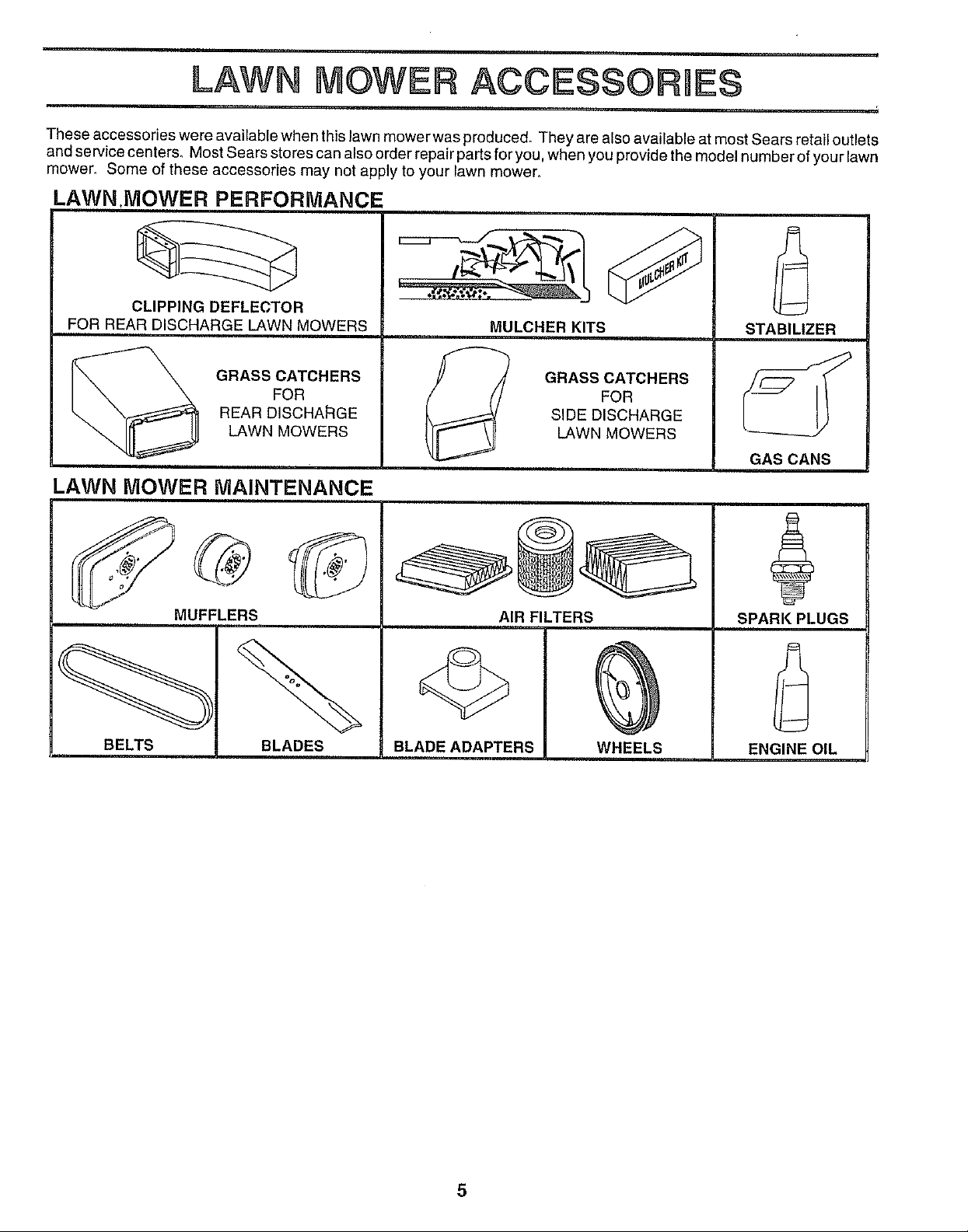
These accessories were available when this lawn mower was produced° They are also available at most Sears retail outlets
and service centers° Most Sears stores can also order repair parts for you, when you provide the model number of your lawn
mower., Some of these accessories may not apply to your lawn mower,
ACCESSORU
LAWN.MOWER PERFORMANCE
CLIPPING DEFLECTOR
FOR REAR DISCHARGE LAWN MOWERS
MULCHER KITS
STABILIZER
GRASS CATCHERS
FOR
REAR DISCHARGE
LAWN MOWERS
LAWN MOWER MAINTENANCE
MUFFLERS
BELTS
BLADES
GRASS CATCHERS
FOR
SIDE DISCHARGE
LAWN MOWERS
AIR FILTERS
BLADE ADAPTERS WHEELS
GAS CANS
SPARK PLUGS
ENGINE OIL
Page 6
ASSEMBLY
Read these instructions and this manual in its entirety
before you attempt to assemble or operate your new lawn
mower_ Your' new lawn mower has been assembled at the
factory with the exception of those parts left unassembled
for shipping purposes. All parts such as nuts, washers,
bolts, etc. necessary to complete the assembly have been
placed in the parts bag. To ensure safe and proper
operation of your' lawn mower, all parts and hardware you
assemble must be tightened securely. Use the correct
tools as necessary to ensure proper tightness
TO REMOVE LAWN MOWER FROM
CARTON
° Remove loose parts included with mower
Cut down two end corners of carton and lay end panel
down flat.
Remove all packing materials except padding between
upper and lower handle and padding holding operator
presence control bar to upper handle.
Roll lawn mower' out of carton and check carton thor-
oughly for additional loose part&
HOWTO SET UPYOUR LAWN MOWER
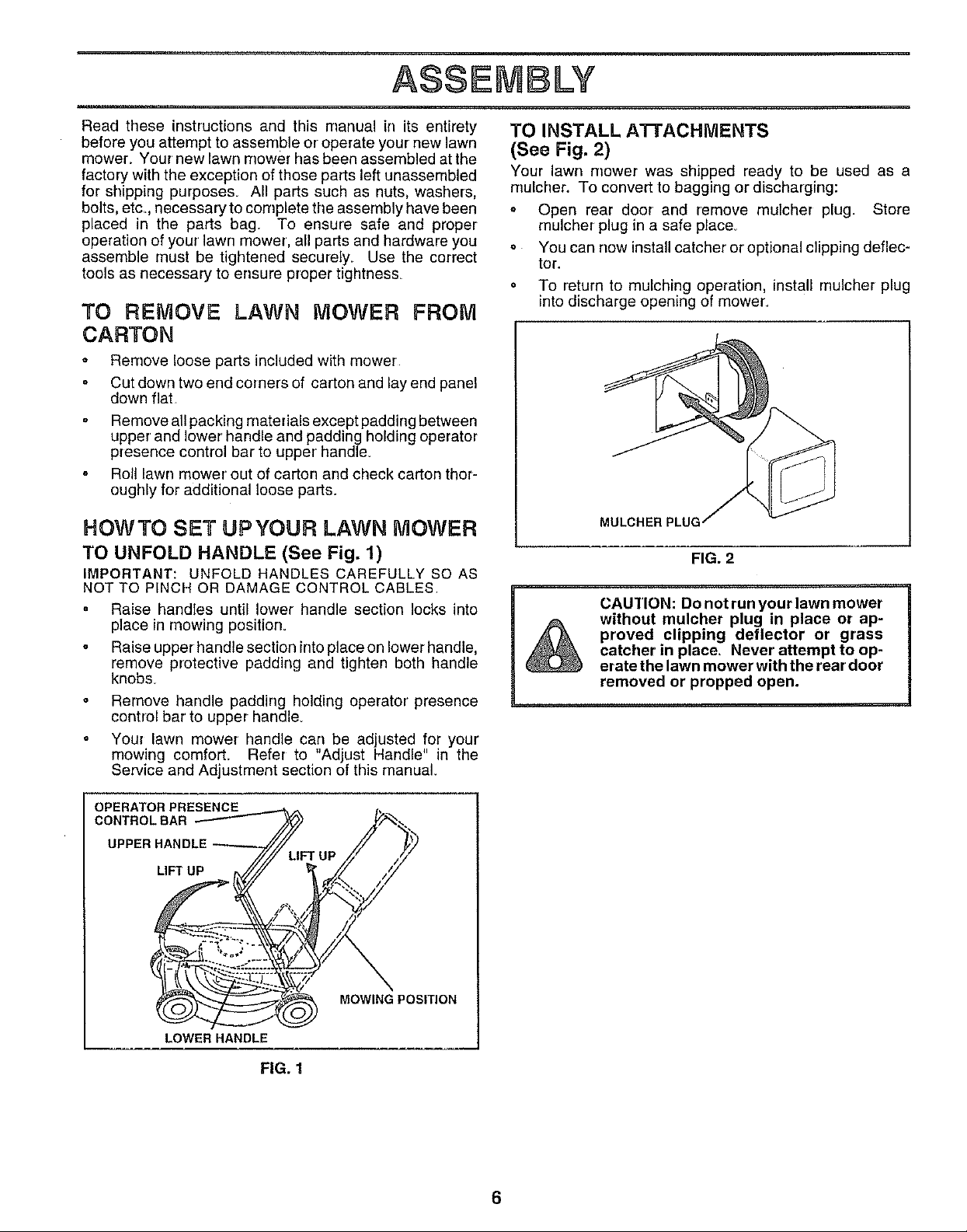
TO UNFOLD HANDLE (See Fig. 1)
IMPORTANT: UNFOLD HANDLES CAREFULLY SO AS
NOT TO PINCH OR DAMAGE CONTROL CABLES
° Raise handles until lower handle section locks into
place in mowing position.
. Raise upper handle section into place on lower handle,
remove protective padding and tighten both handle
knobs
Remove handle padding holding operator' presence
control bar to upper handle.
Your lawn mower handle can be adjusted for your
mowing comforL Refer to "Adjust Handle" in the
Service and Adjustment section of this rnanual.
TO INSTALL A'I-rACHMENTS
(See Fig. 2)
Your lawn mower was shipped ready to be used as a
mulcher, To convert to bagging or discharging:
= Open rear door and remove mulcher plug. Store
mulcher plug in a safe piace.
• You can now install catcher or optional clipping deflec-
tor.
o To return to mulching operation, install mulcher plug
intodischarge opening of mower.
FIG. 2
CAUTION: Do not run your lawn mower
without mulcher plug in place or ap-
proved clipping deflector or grass
catcher in place, Never attempt to op-
erate the lawn mower with the rear'door
removed or propped open,
OPERATOR PRESENCE
CONTROLBAR
UPPER HANDLE
LIFT UP
LOWER HANDLE
MOWING POSITION
FIG. 1
6
Page 7
BLY
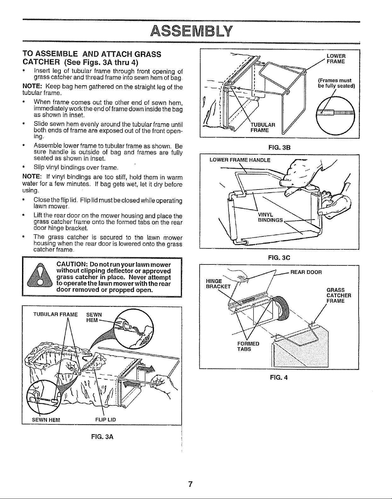
TO ASSEMBLE AND ATTACH GRASS
CATCHER (See Figs. 3A thru 4)
° Insert leg of tubular frame through front opening of
grass catcher and thread frame into sewn hem of bag
NOTE: Keep bag hem gathered on the straight leg of the
tubular frame,
• When frame comes out the other end of sewn hem,
immediately work the end of frame down inside the bag
as shown in inseL
o Slide sewn hem evenly around the tubular frame until
both ends of frame are exposed out of the front open-
ing_
° Assemble lower frame to tubular frame as shown. Be
sure handle is outside of bag and frames are fully
seated as shown in inset.
• Slip vinyl bindings over frame.
NOTE: If vinyl bindings are too stiff, hold them in warm
water for a few minutes. If bag gets wet, let it dry before
using.
° Close the flip lid, Flip lid must be closed while operating
lawn mower
Lift the rear door on the mower housing and place the
grass catcher frame onto the formed tabs on the rear
door hinge brackeL
The grass catcher is secured to the lawn mower
housing when the rear door is lowered onto the grass
catcher frame,
CAUTION: Do not run your lawn mower
without clipping deflector or approved
grass catcher in place. Never attempt
to operate the lawn mower with the rear
door removed or propped open.
dr-/ I', _ // !1 (Framesmust
I
I
//J;
LOWER FRAME HANDLE
\
BRACKET
LOWER
FIG. 3B
FIG, 3C
DOOR
GRASS
CATCHER
FRAME
TUBULAR
SEWN HEM
FRAME SEWN
FORMED
TABS
FIG. 4
FLIP LID
FIG. 3A
Page 8

OPERATION
KNOW YOUR LAWN MOWER
READ THIS OWNER'S MANUAL AND SAFETY RULES BEFORE OPERATING YOUR LAWN MOWER_ Compare the
illustrations with your lawn mower to familiarize yourself with the location of various controls and adjustments, Save this
manual for future reference,.
These symbols may appear on your lawn mower or in literature supplied with the product. Learn and understand
their meaning.
CAUTION FAST FUEL
OR WARNING
STARTER HANDLE
GRASS CATCHER
ENGINE ENGINE
ON OFF
HANDLE KNOB
SLOW CHOKE OIL DANGER, KEEP HANDS
AND FEET AWAY
OPERATOR PRESENCE CONTROLBAR
GASOLINE FILLER CAP
MULCHER PLUG
ENGINE OIL CAP
WITH DIPSTICK
LAWN MOWER HOUSING
WHEEL ADJUSTER
(ON EACH WHEEL)
MEETS CPSC SAFETY REQUIREMENTS
Sears rotary walk-behind power lawn mowers conform to the safety standards of the American National Standards Institute
and the U.S. Consumer Product Safety Commission_ The blade turns when the engine is running.
OPERATOR PRESENCE CONTROL BAR - must be held
down to the handle to start the engine. Release to stop the
engine_
PRIMER - pumps additional fuel from the carburetor to the
STARTER HANDLE - used for' starting the engine=
MULCHER PLUG - located at the discharge opening must
be removed when converting to bagging or discharging
operation
cylinder for use when starting a cold engine.
8
Page 9

OPERATION
The operation of any lawn mower can result in foreign objects thrown into the eyes, which can
result in severe eye damage. Always wear safety glasses or eye shields while operating your
I
HOWTO USEYOUR LAWN MOWER
ENGINE SPEED
The engine speed was set at the factory for optimum
performance_ Speed is not adjustable.
ENGINE ZONE CONTROL
CAUTION: Federal regulations require
an engine control to be installed on this
lawn mower in order to minimize the
risk of blade contact injury. Do not
&
o Your lawn mower is equipped with an operator pres-
ence control bar which requires the operator to be
positioned behind the lawn mower handle to start and
operate the lawn mower.
TO ADJUST CUTTING HEIGHT (See Fig. 5)
Raise wheels for low cut and lower wheels for high cuL
• Adjust cutting height to suit your requirements. Me-
dium position is best for most lawn&
• To change cutting height, squeeze adjuster lever to-
ward wheel Move wheel up or down to suit your
requirements Be sure all wheels are in the same
setting.
NOTE: Adjuster is properly positioned when plate tab
inserts into hole in lever Also, 9-position adjusters (if so
equipped) allow lever to be positioned between the plate
tabs.
LOWER WHEELS PLATE TAB
FOR HIGH CUT
RAISE WHEELS
FOR LOW CUT
TO EMPTY GRASS CATCHER (See Fig. 6)
Lift up on grass catcher using the frame handle
o Remove grass catcher with clippings from under lawn
mower handle.
o Empty clippings from bag using both frame handle and
bag handle
NOTE: Do not drag the bag when emptying; it will cause
unnecessary wear.
tinder any circumstances attempt to
defeat the function of the operator con-
trol. The blade turns when the engine is
running.
lawn mower or performing any adjustments or repairs. We recommend a wide vision safety
mask over the spectacles or standard safety glasses.
LEVER
FIG. 5
FIG. 6
BEFORE STARTING ENGINE
OIL (See Fig. 7)
Your lawn mower is shipped without oil in the engine.
• Be sure mower islevel and area around oil fill is clean.
• Remove engine oil cap w/dipstick and fill to the full line
on the dipstick.
° Use20ezs of oil. Fortypeandgradeofoiltouse, see
"ENGINE" in Customer Responsibilities section of this
manual.
° Pour oil stowly Do not over fill.
° Check oil level before each use. Add oil if needed. Fill
to full line on dipstick.
• To read proper level, tighten engine oil cap each time_
° Reinstall engine oil cap and tighten.
• After the first two (2) hours of mowing, change the oil,
and every 25 hours thereafter You may need to
change the oil more often under dusty, dirty conditions..
GAS (See Fig. 7)
° Fill fuel tank. Use fresh, clean, regular unleaded
gasoline with a minimum of 87 octane. Do not mix oil
with gasoline. Purchase fuel in quantities that can be
used within 30 days to assure fuel freshness.
WARNING: Experience indicates that alcohol blended
fuels (called gasohel or using ethanol or methanol) can
attract moisture which leads to separation and formation of
acids during storage_ Acidic gas can damage the fuel
system of an engine while in storage. To avoid engine
problems, the fuel system should be emptied before stor-
age of 30 days or longer. Drain the fuel tank, start the
engine and let it run until fuel lines and carburetor are
empty. Use flesh fue_ next season See Storage _nstruc-
tions for additional information. Never use engine or
carburetor cleaner products in fuel tank or permanent
damage may occur.
FILLER CAP
ENGINE OIL CAP
W/DIPSTICK
9
FIG. 7
Page 10

OPERATION
TO START ENGINE
To start a cold engine, push primer five (5) times before
trying to start. Use a firm push. This step is not usually
necessary when starting an engine which has already
run for a few minutes.
. Hold operator presence control bar down to the handle
and pul! starter handle quickly Do not allow starter
rope to snap back.
• To stop engine, release operator presence control bar'
NOTE: In cooler weather it may be necessary to repeat
priming steps In warmer weather over priming maycause
flooding and engine will not start. If you do flood engine,
wait a few minutes before attempting to start and do not
repeat priming steps
MOWING TiPS
• Undercertain conditions, such as very tall grass, it may
be necessary to raise the height of cut to reduce
pushing effort and to keep from overloading the engine
and leaving clumps of grass clippings°
For extremely heavy cutting, reduce the width of cut
and raise the rear of the lawn mower housing one (1)
wheel adjuster setting higher than the front for better
discharge of grass.
o When using a rear discharge lawn mower in moist,
heavy grass, clumps of cut grass may not enter the
grass catcher. Reduce ground speed (pushing speed)
and/or run the lawn mower over the area asecond time.
= If a trail ofgrass clippings is left onthe rightside of a rear
discharge lawn mower, mow in a clockwise direction
with a small overlap to collect the clippings on the next
pass
. Keep top of engine around starter clear and clean of
grass clippings and chaff. This will help engine airflow
and extend engine life.
= Pores in cloth grass catchers can become filled with dirt
and dust with use and catchers will collect less grass.
To prevent this, regularly hose catchers off with water
and let dry before using.
MULCHING MOWING TiPS
IMPORTANT: FOR BEST PERFORMANCE, KEEP
MOWER HOUSING FREE OF BUILT-UP GRASS AND
TRASH CLEAN UNDERSIDE OF MOWER HOUSING
AFTER EACH USE. SEE "CLEANING" IN CUSTOMER
RESPONSIBILITIES SECTION OF THIS MANUAL.
° The special mulching blade will recut the grass clip-
pings many times and reduce them in size so that as
they fall onto the lawn they will disperse into the grass
and not be noticed_ Also, the mulched grass will
biodegrade quickly to provide nutrients for the lawn.
Always mulch with your highest engine (blade) speed
as this will provide the best recurring action of the
blades_
o Avoid cutting your lawn when it is weL Wet grass tends
to form clumps and interferes with the mulching action.
The best time to mow your lawn is the early afternoon.
At this time the grass has dried and the newly cut area
will not be exposed to the direct sun.
. For best results, adjust the lawn mower' cutting height
so that the lawn mower cuts off only the top one-third
of the grass blades (See Fig. 8)_ If the lawn is over-
grown it will be necessary to raise the height of cut to
reduce pushing effort and to keep from overloading the
engine and leaving clumps of mulched grass. For
extremely heavy mulching, reduce your width of cut,
mow slowly and raise the rear of the lawn mower one
wheel adjuster setting higher than the frenL
° Certain types of grass and grass conditions may re-
quire that an area be mulched a second time to com-
pletely hide the clippings. When doing a second cut,
mow across or perpendicular to the first cut path.
Change your cutting pattern from week to week. Mow
north to south one week then change to east to west the
next week.. This will help prevent matting and graining
of the lawn.
MAX 1/3
10
FIG. 8
Page 11

CUSTOMER RESPONSaBILmT ES
MAINTENANCE SCHEDULE _._'_._, _'O_,_%-_ _._£,_Y
FILL IN DATES
AS YOU COMPLETE
Check for Loose Fasteners 6/ 6#"'
Clean/Inspect Grass Catcher
(If Equipped) 6/'
M Clean Lawn Mower
J J
(Power-Propelled Mowers)
O Clean Under Drive Cover
Check drive belt/pulleys
_ Power-Propelled Mowers)
Check/Sharpen/Replace Blade
Lubrication Chart
Clean Battery/Recharge
{Electric Start Mowers)
Check Engine Oil Level 6f
N Change Engine Oil
G Clean Air Filter
Inspect Muffler
N Clean or Replace Spark Plug
E Replace Air Filter Paper Cartridge
1 - Change more often when operating under a heavy load or in high ambient temperafures
2 - Service more often when operaling in dirty or dusty conditions
3 - Replace blades more often when mowing in sandy soil
4 - Charge 48 hours at end of season
e,'
e,"
GENERAL RECOMMENDATIONS
The warranty on this lawn mower does not cover items that
have been subjected to operator abuse or negligence, To
receive full value from the warranty, operator must maintain
mower as instructed in this manual,
Some adjustments will need to be made periodically to
properly maintain your uniL
All adjustments in the Service and Adjustments section of
this manual should be checked at least once each season.
• Once a year, replace the spark plug, replace air filter
element and check blade for wear. A new spark plug
and clean/new air filter element assures proper air-fuel
mixture and helps your engine run better and last
longer
• Follow the maintenance schedule in this manual.
V%
J V',
J
J2
/'/
LUBRICATION CHART
WHEEL
(_BRAKE
SPRING
BRACKET
(_) ENGINE OIL
BEFORE EACH USE
• Check engine oil level.
° Check for loose fastener&
LUBRICATION
Keep unit well lubricated (See "LUBRICATION CHART")
(_)HANDLEBRACKET " REAR
MOUNTING PIN _DOOR
HINGE
(_)SPRAYLUBRICANT
(_)SAE30MOTOROIL. REFERTOENGINE-CUSTOMERRESPON-
SIBILITIES SECTION,
IMPORTANT: DO NOT OIL OR GREASE PLASTIC WHEEL
BEARINGS VISCOUS LUBRICANTS WILL ATTRACT
DUST AND DIRT THAT WILL SHORTEN THE LIFE OF
THE SELF LUBRICATING BEARINGS. IF YOU FEEL THEY
MUST BE LUBRICATED, USE ONLYA DRY, POWDERED
GRAPHITE TYPE LUBRICANT SPARINGLY
'11
Page 12

CUSTOMER RESPONSmB LITUE$
LAWN MOWER
Always observe safety rules when performing any mainte-
nance
TIRES
= Keep tires free of gasoline, oil, or insect control chemi-
cals which can harm rubber.
Avoid stumps, stones, deep ruts, sharp objects and
other hazards that may cause tire damage.
BLADE CARE
For best results, mower blade must be kept sharp= Replace
bent or damaged blades
TO REMOVE BLADE (See Fig_ 9)
• Disconnect spark plug wire from spark plug and place
wire where it cannot come in contact with spark plug.
• Turn lawn mower on its side_ Make sure air filter and
carburetor are up.
Use a wood block between blade and mower housing
to prevent blade from turning when removing blade
bolt.
Protect your hands with gloves and/or wrap blade with
heavy cloth.
o Remove blade bolt by turning counter-clockwise. Use
a 9/16" box or open-end wrench.
o Remove blade and attaching hardware (bolt, lock
washer and hardened washer)_
NOTE: Remove the blade adapter and check the key
inside hub of blade adapter. The key must be in good
condition to work properly. Replace adapter if damaged.
TO REPLACE BLADE (See Fig. 9)
o Position the blade adapter on the engine crankshafL
Be sure key in adapter and keyway in crankshaft are
aligned.
Position blade on the blade adapter aligning the two (2)
holes in the blade with the raised lugs on the adapter_
Be sure the trailing edge is up toward the engine_
o Install the blade bolt with the Iockwasher and hardened
washer into blade adapter and crankshaft,
• Use block of wood between blade and lawn mower
housing and tighten the blade bolt, turning clockwise.
o The recommended tightening torque is 35-40 ft. Ibs.
IMPORTANT: BLADE BOLT IS GRADE 8 HEATTREATED
BLADE CRANK-
ADAPTER
BLADE
HARDENED
WASHER
LOCK WASHER EDGE
TRAILING
BLADE ADAPTER
KEYWAY
'CRANK-
SHAFT
FIG. 9
NOTE: We do not recommend sharpening blade- but ifyou
do, be sure the blade is balanced.
TO SHARPEN BLADE
Care should be taken to keep the blade balanced. An
unbalanced blade will cause eventual damage to lawn
mower or engine_
• The blade can be sharpened with a file or on agrinding
wheel Do not attempt to sharpen while on the mower.
o To check blade balance, ddve a nailinto a beam orwallo
Leave about one inch of the straight nail exposed.
Place center hole of blade over the head of the nail. If
blade is balanced, it should remain in a horizontal
position If either end of the blade moves downward,
sharpen the heavy end until the blade is balanced_
GRASS CATCHER
o
The grass catcher may be hosed with water, but must
be dry when used.
o
Check your grass catcher often for damage or deterio-
ration. Through normal use it will wear. If catcher
needs replacing, replace only with a manufacturer
approved replacement catcher. Give the lawn mower
model number when ordering.
12
Page 13

CUSTOM RESPONS BDLRTmES
ENGINE AIR FILTER
LUBRICATION
Use only high quality detergent oil rated with APt service
classification S For SG, Select the oil's SAE viscosity grade
according to your expected operating temperature.
SAE VISCOSITY GRADES
"20 ° 0" 60 ° 80°
TEMPERATURE RANGE ANTICIPATED BEFORE NEXT OIL CHANGE
NOTE: Although multi-viscosity oils (5W30, 10W30 etc,)
improve starting in cold weather, these multi-viscosity oils
will result in increased oil consumption when used above
32°F, Check your engine oil level more frequently to avoid
possible engine damage from running low on oil
Change the oil after the first two hours of operation and
every 25 hours thereafter or at least once ayear if the lawn
mower is net used for 25 hours in one year.
Check the crankcase oil level before starting the engine
and after each five (5) hours of continuous use, Tighten oil
plug securely each time you check the oil level
TO CHANGE ENGINE OIL (See Fig. 10)
NOTE: Before tipping lawn mower to drain oil, drain fuel
tank by running engine until fuel tank is empty.
Disconnect spark plug wire from spark plug and place
wire where it cannot come in contact with spark plug.
Remove engine oil cap; lay aside on a clean surface.
o Tip lawn mower on its side and drain oil into a suitable
container. Rock lawn mower back and forth to remove
any oil trapped inside of engine.
• Wipe off any spilled oil on lawn mower and on side of
engine.
• Fill engine with oil. Fill only to the "FULL" line on the
dipstick. DO NOT OVER FILL
o Replace engine oil cap,
• Reconnect spark plug wire to spark plug
Your engine will not run properly and may be damaged by
using a dirty air filter.
Replace the air filter every year, more often if you mew in
very dusty, dirty condition& Do not wash air filter.
TO
CHANGE AIR FILTER (See Fig_ 11)
o
Remove the air filter cover by turning counterclockwise
to the stop and pull away from collar.
Remove filter from inside of cover.
o Clean the inside of the cover and the collar to remove
any dirt accumulation°
° Insert new filter into cover_
Put air filter cover and filter into collar aligning the tab
with the slot.
° Push in on cover and turn clockwise to tighten,
COLLAR
SLOT
MUFFLER
Inspect and replace corroded muffler as it could create a
fire hazard and/or damage,
SPARK PLUG
Change your spark plug each year to make your engine
start easier and run better. Set spark plug gap at .030 inch.
CLEANING
IMPORTANT: FOR BEST PERFORMANCE, KEEP
MOWER HOUSING FREE OF BUILT-UP GRASS AND
TRASH CLEAN UNDERSIDE OF MOWER HOUSING
AFTER EACH USE,
COUNTER-
CLOCKWISE
TO REMOVE
AIR FILTER COVER TO TIGHTEN
FIG. 11
CONTAINER
FIG. 10
from spark plug and place wire where it
cannot come in contact with the spark
I & CAUTION: Disconnect spark plug wire
plug.
Turn lawn mower on its side,. Make sure air filter and
carburetor are up, Clean the underside of your lawn
mower by scraping to remove build-up of grass and
trash.
° Clean engine often to keep trash from accumulating. A
clogged engine runs hotter and shortens engine life.
o Keep finished surfaces and wheels free of all gasoline,
oi!, etc.
We DO NOT recommend using a garden hose to clean
lawn mower unless the electrical system, muffler, air
filter and carburetor are covered to keep water ouL
Water in engine can result in shortened engine life.
13
Page 14

SERVMCE ADJUSTMENTS
I _ CAUTION: BEFORE PERFORMING ANY SERVICE OR ADJUSTMENTS:
o Release control bar. I
= Make sure the blade and all moving parts have completely stopped.
° Disconnect Spark plug wire from spark plug and place where it cannot come in contact with plug,
LAWN MOWER
TO ADJUST CUTTING HEIGHT
See "TO ADJUST CUTTING HEIGHT" in the Operation
section of this manual
REAR DEFLECTOR
The rear' deflector, attached between the rear wheels of
your' lawn mower, is provided to minimize the possibility
that objects will be thrown out the rear of the lawn mower
into the operator's mowing position_
If the rear deflector becomes damaged, it should be re-
placed,
TO ADJUST HANDLE (See Figs. 12 Thru 14)
Your lawn mower handle can be raised or lowered for your
mowing comfort, Four (4) positions are available: high,
medium high, medium low and low, Handles are shipped
mounted in the medium low position.
To change from medium low to medium high position,
the upper and lower handle sections will have to be
turned over (See Fig. 12B).
Remove the cable clips.
• Remove the controls and operator presence control
bar from the upper handle.
° Remove the starter rope guide from the lower handle
Remove hairpin cotters,
Disconnect the lower handle from the handle brackets
(See Fig_ 14)
° Turn the handle over and reassemble the hairpin
cotters that have been removed_
. Reassemble the starter rope guide.
• Reassemble the controls and the operator presence
control bar' to the upper handle_
CAUTION: The operator presence con-
trol bar must pivot freely to permit blade
brake engagement when control bar is
released. Do not over tighten the fas-
teners holding the controls to the up-
per handle.
SHIPPING POSITION
MEDIUM LOW
FIG. 12A FIG. 12B
FIG. 13A FIG. 13B
SQUEEZE
TO REMOVI
MEDIUM HIGH
LOW
LOWER HANDLE
o To change from medium low to high position only the
upper handle section will have to be turned over (See
Fig_ 13A).
o To change from medium low to low position, only the
lower handle section will have to be turned over (See
Fig. 13B)_
ENGINE
CARBURETOR
Your carburetor has a non-adjustable fixed main jet for
mixture control. If your engine does not operate properly
due to suspected carburetor problems, take your lawn
mower to an authorized service center for repairor adjust-
ment
HAIRPIN CLIP
FIG. 14
ENGINE SPEED
Your engine speed has been factory set. Do not attempt
to increase engine speed or itmay result in personal injury,
If you believe that the engine is running too fast or too stow,
take your lawn mower to an authorized service center for
repair and adjustment.
14
Page 15

STORAGE
i
Immediately prepare your lawn mower for storage at the ENGINE
end of the season or if the unit will not be used for 30 days
or more.
LAWN MOWER
When lawn mower is to be stored for a period of time, clean
it thoroughly, remove all dirt, grease, leaves, etc. Store in
a clean, dry area.
o Clean entire lawn mower (See "CLEANING" in the
Customer Responsibilities section of this manual).
= Lul_dcate as shown in the Customer Responsibilities
section of this manual..
o Be sure that all nuts, bolts, screws, and pins are
securely fastened_ Inspect moving parts for damage,
breakage and wear. Replace if necessary.
o Touch up all rusted or chipped paint surfaces; sand
lightly before painting.
HANDLE (See Fig. 15)
You can fold your lawn mower handle for storage_
• Squeeze the bottom ends of the lower handle toward
each other until the lower handle clears the handle
bracket, then move handle forward.
Loosen upper handle mounting bolts enough to allow
upper handle to be folded back.
IMPORTANT: WHEN FOLDING THE HANDLE FOR
STORAGE OR TRANSPORTATION, BE SURE TO FOLD
THE HANDLE AS SHOWN OR YOU MAY DAMAGE THE
CONTROL CABLES
When setting up your handle from the storage position,
the lower handle will automatically lock into the mowing
position.
LOWER HANDLE
HANDLE
KET
FUEL SYSTEM
IMPORTANT: IT IS IMPORTANT TO PREVENT GUM
DEPOSITS FROM FORMING IN ESSENTIAL FUEL
SYSTEM PARTS SUCH AS CARBURETOR, FUEL FILTER,
FUEL HOSE, OR TANK DURING STORAGE. ALSO,
EXPERIENCE INDICATES THAT ALCOHOL BLENDED
FUELS (CALLED GASOHOL OR USING ETHANOL OR
METHANOL) CAN ATTRACT MOISTURE WHICH LEADS
TO SEPARATION AND FORMATION OF ACIDS DURING
STORAGE. ACIDIC GAS CAN DAMAGE THE FUEL
SYSTEM OF AN ENGINE WHILE IN STORAGE
Drain the fuel tank
o Start the engine and let it run until the fuel lines and
carburetor are empty.
• Never use engine orcarburetor cleaner products in the
fuel tank or permanent damage may occur,
o Use fresh fuel next season,,
NOTE: Fuel stabilizer is an acceptable alternative in
minimizing the formation of fuel gum deposits during stor-
age. Add stabilizer to gasoline in fuel tank or storage
container. Always follow the mix ratio found on stabilizer
container. Run engine at least 10 minutes after adding
stabilizer to allow the stabilizer to reach the carburetor, Do
not drain the gas tank and carburetor if using fuel stabilizer.
ENGINE OIL
Drain oil (with engine warm) and replace with clean engine
oil (See "ENGINE" in the Customer Responsibilities
section of this manual).
CYLINDER
o Remove spark plug.
o Pour one ounce (29 ml) of oil through spark plug hole
into cylinder_
= Pull starter handle slowly a few times to distribute oil.
• Replace with new spark plug_
SQUEEZE TO
FOLD
OPERATOR PRESENCE
CONTROLBAR
UPPER HANDLE _
FOLDFORWARB
FOR STORAGE
LOWER HANDLE
FIG. 15
HAIRPIN
COTTER
FOLD BACKWARD
MOWING
POSITION
OTHER
o Do not store gasoline from one season to another.,
o Replace your gasoline can if your can starts to rust.,
Rust and/or dirt in your gasoline will cause problems_
° If possible, store your unit indoors and cover it to give
protection from dust and dirt.
° Cover your unit with a suitable protective cover that
does not retain moisture, Do not use plastic. Plastic
cannot breathe which allows condensation to form and
will cause your unit to rusL
IMPORTANT: NEVER COVER MOWER WHILE ENGINE
AND EXHAUST AREAS ARE STILL WARM.
CAUTION: Never store the lawn mower
with gasoline in the tank inside abuild-
ing where fumes may reach an open
flame or spark. Allow the engine to
cool before storing in any enclosure.
15
Page 16

REPAURPARTS
CRAFTSMAN 20" ROTARY LAWN MOWER - - MODEL NO. 917.387130
11
58
7
\
.,,&
57
8
9
24
17
28
\
44
35
32 33
37
37
32
36 38
43
42
43
40
38
39
40
39
,55
,54
43
4o
39
43
50
38
Page 17

REPAIR PARTS
CRAFTSMAN 20" ROTARY LAWN MOWER - - MODEL NO. 917.387130
"4
KEY PART
NO. NO.
1 86902
2 145646x479
3 150424
4 132001
5 !51516X479
7 131959
8 151517
9 51793
t0 136376
tl 156577
13 750097
14 850733X004
15 63601
17 147613
18 700357X479
19 150050
2! 54583
22 700063X479
23 88652
24 700363X479
25 144875X479
26 140657
28 151512X479
29 151511X479
31 150078
32 700325X007
33 146630
34 128415
35 87877
36 700331X004
37 145935X004
DESCRIPTION KEY PART DESCRIPTION
NO. NO.
Control Bar
Upper Handle
Mulcher Plug
Rope Guide
Lower Handle
Handle Bolt
Cable Clip
Hairpin Cotter
Handle Knob
Engine Zone Control Cable
Hex Washer Head Screw 10-24 x 1/2
Up-Stop Bracket
Keps Locknut 1/4-20
Rear Door Assembly Kit
Back Plate
Self Tapping Screw 10-24 x 5/8
Hex Head Tapping Screw 1/4-20 × 1/2
Rear Baffle
Hinge Screw 1/4-20 x 1-1/4
Side Baffle
Discharge Baffle
Rear Deflector
Handle Bracket Assembly (Left)
Handle Bracket Assembly (Right)
Screw 5/16-18 x 3/4
Wheel Adjusting Bracket
Spacer
Pop Rivet
Selector Knob
Selector Spring
Axle Arm Assembly
38 62335
39 142748
40 151157
42 83923
43 774OO
44 85463
45 150406
46 48395
47 751592
50 700938X479
51 851084
52 850263
53 851074
54 145106
55 850977
56 144748
57 149844
58
59 144747
-- 156597
Available accessories not included with lawn mower:
71 33723 Hi-Wheel Kit
7_!33623 Gas Can (2.5 gal.)
71 33500 Fuel Stabilizer
71 33300 SAE 30W Oil (20 oz.)
7.133417 Dust Shield
7"133316 Mower Cover
Belleville Washer
Shoulder Bolt
Wheel and Tire Assembly
Hex Flange Locknut
Hubcap
Danger Decal
Hex Head Thread Rolling Screw 3/8-16 x 1
Lawn Mower Housing (Incl. Key #18, 22, 24, 44, 50)
Locknut 3/8-16
Front Baffle
Hex Head Machine Screw 3/8-24 x 1-3/8 (Grd. 8)
Helical Lockwasher 3/8
Washer
Blade 20"
Blade Adapter
Tube Frame
Grass Bag
Engine - (See Breakdown) Craftsman
Model 143.974500
Throat Frame
Owner's Manual
Page 18

CRAFTSMAN 4=CYCLE ENGUNE MODELNUMBER143.974500
9O0
400
135
130
416
182 ^._ 19
126
120
119
125
"_'310
%
'174
30
46
_307
241
</_ 245
238 250
18
Page 19

CRAFTSMAN 4=CYCLE ENGINE MODELNUMBER143.974500
REF PART REF PART
NO. NO. DESCRIPTION NO. NO. DESCRIPTION
1 36478A
2 26727
6 33734
7 36557
12A 36558
12B 34695
14 28277
15 30589
16 32651
17 31335
18 651018
'19 36281
20 32600
30 35996
40 36073
40 36074
40 36075
41 36070
41 36071
41 36072
42 36076
42 36077
42 36078
43 20381
45 30963B
46 32610A
48 27241
50 35992
52 29914
69 35261
70 34311D
72 36083
75 27897
80 30574A
81 30590A
82 30591
83 30588A
86 650488
89 611004
90 611112
92 650815
93 650816
100 34443A
101 610118
103 651007
110 34961
119 36477
120 36476
125 36471
125 36472
126 29314B
126 29315C
130 6021A
135 35395
150 35991
151 31673
169 27234A
172 32755
174 30200
178 29752
182 6201
184 26756
185 36544
Cylinder (Incl 2,7,20 & 125) 186 34337
Dowel Pin 189 650839
Breather Element 191 36559
BreatherAss'y. (Incl 5 & 12A) 195 610973
Breather Cover & Tube (IncL 12B) 200 35727
Breather Tube Elbow 202 36482
Washer 203 31342
Governor Rod (lncL. 14) 204 650549
Governor Lever 205 650777
Governor Lever Clamp 207 34336
Screw, Torx T-15, 8-32 x 19/64" 209 30200
Extension Spring 215 32410
Oil Seal 223 650451
Crankshaft 224 34690A
Piston, Pin & Ring Set (Std.) 238 650932
Piston, Pin & Ring Set (.010" OS) 239 34338
Piston, Pin & Ring Set (.020" OS) 241 35797
Piston & Pin Ass'y. (Std_) (tncL 43) 245 35066
Piston & Pin Ass'y. 250 35065
(.010" OS) (IncL 43) 260 36915
Piston & Pin Ass'y. 261 30200
(.020" OS) (IncL 43) 262 650831
Ring Set (Std.) 275 36473
Ring Set (.010" OS) 277 650988
Ring Set (.020" OS) 285 35000A
Piston Pin Retaining Ring 287 650926
Connecting Rod Ass'y. (Incl. 46) 290 30705
Connecting Rod Bolt 292 26460
Valve Lifter 298 28763
Camshaft (MCR) 300 36916
Oil Pump Ass'y_ 301 36246
* Mounting Flange Gasket 305 35647
Mounting Flange (Incl 72 thru 83) 306 36832
Oil Drain Plug 307 35499
Oil Seal 309 650562
Governor Shaft 310 35648
Washer 313 34080
Governor Gear Ass'y. (Incl 81) 370A 36261
Governor Spool 370B 35167
Screw, 1/4-20 x 1-1/4" 370C 36861
Flywheel Key 370K 36695
Flywheel 380 632747
Belleville Washer 390 590694
Flywheel Nut 400 36481
Solid State Ignition
Spark Plug Cover 416 36085
Screw, Torx T-15, 10-24 x 15/16"
Ground Wire 417 650760
* Cylinder Head Gasket 900 --
Cylinder Head 900 --
Exhaust Valve (Std.) (Incl 151)
Exhaust Valve
(1/32" OS) (Incl.. 151)
Intake Valve (Std.) (IncL 151)
Intake Valve (1/32" OS) (IncL 151)
Screw, 5/16-18 x 1-1/2"
Resistor Spark Plug (RJ19LM)
Valve Spring
Valve Spring Cap
* Valve Cover Gasket
Valve Cover
Screw, 10-24 x 9/16"
Nut & Lock Washer, 1/4-28
Screw, 1/4-28 x 7/8"
* Carburetor To Intake Pipe Gasket
Intake Pipe
(NOTE: This engine could have been built with 590737
starter.. Refer to the design of the rope pulley strength
ribs for part identification. Individual starter parts do not
interchange.) IncL Part #'s 26756 (1),27234A (1), 33735
(1), 36832 (1), 34338 (1), 34690A (1), 35261 (1),
36477 (1)
NOTE: All component dimensions given in U.S. inches
1 inch = 254 mm
19
Governor Link
Screw, 1/4-20 x 3/8"
SE Brake Bracket (Incl. 195)
Terminal
Control Bracket (Incl. 202 Thru 205)
Compression Spring
Compression Spring
Screw, 5-40 x 7/16"
Screw, 6-32 x 21/32"
Throttle Link
Screw, t0-24 x 9/16"
Control Knob
Screw, 1/4-20 x 1"
* Intake Pipe Gasket
Screw, 10-32 x 49/64"
* Air Cleaner Gasket
Air Cleaner Collar
Air Cleaner Filter
Air Cleaner Cover
Blower Housing
Screw, 10424 x 9/16"
Screw, 1/4-20 x 1/2"
Muffler (Incl, 277)
Screw, 1/4-20 x 2-5/16"
Starter Cup
Screw, 8*32 x 21/64"
Fuel Line
Fuel Line Clamp
Screw, 10-32 x 35/64"
Fuel Tank (Incl 292 & 301)
Fuel Cap
Oil Fill Tube
* "O"-Ring
"O"-Ring
Screw, 10-32 x 1/2"
Dipstick
Spacer
Lubrication Decal
Control Decal
Primer Decal
Starter Decal
Carburetor (IncL 164)
Rewind Starter
Gasket Set
(IncL Items Marked * in Notes)
Spark Arrestor Kit
(Incl., 417)(Optional)
Screw, 8-32 x 3/8" (Optional)
Replacement Engine NONE
Replacement S/B 750679A,
order from 71-999
RPM High 2900 to 3200
RPM Low 2450 to 2750
Page 20

CRAFTSMAN &CYCLE ENGINE MODELNUMBER143.974500
REF PART
NO. NO. DESCRIPTION
48_O _ -49
I SO
28_ %_27
44_!
,-e[
632747
1 631615
2 631767
4 631184
5 631183
6 632504
7 650506
16 631807
25 631867
27 631024
28 632019
29 631028
30 631021
31 631022
35 36045
36 632735
37 632547
40 632736
44 27110
48 631027
REF PART
NO. NO. DESCRIPTION
-- 590694 Recoil Starter
1 590599A Spring Pin (IncL 4)
2 590600 Washer
3 590696 Retainer
ml
4 590601 Washer
5 590697 Brake Spring
6 590698 Starter Dog
7 590699 Dog Spring
8 590700 Pulley & Rewind Spring Ass'y.
11 590695 Starter Housing Ass'yo
12 590535 Starter Rope ( 98" X 9/64" diao)
13 590701 Starter Handle
Carburetor
(IncL 184 of Engine Parts List)
Throttle Shaft & Lever Assembly
Throttle Return Spring
Dust Seal Washer
Dust Seal (Throttle)
Throttle Shutter
Shutter Screw
Fuel Fitting
Float Bowl
Float Shaft
Float
Float Bowl "O" Ring
Inlet Needle, Seat, & Clip (IncL 31)
Spring Clip
Primer Bulb/Retainer Ring
Main Nozzle Tube
"O" Ring, Main Nozzle Tube
High Speed Bowl Nut
Bowl Nut Washer
Welch Plug, Atmospheric Vent
(40 degree grommet)
REF PART
NO. NO. DESCRIPTION
-- 590737 Rewind Starter
3 590740 Retainer
6 590616 Starter Dog
7 590617 Dog Spring
8 590618A Pulley & Rewind Spring Ass'y
11 590687A Starter Housing Ass'y
/
18 EI--_
12 590535 Starter Rope
13 590701 Starter Handle
14 590741 Locking Tab
NOTE: All component dimensions given in U,S, inches
1 inch = 25,,4 mm
I
(40 degree grommet)
(Length 98" x 9/64" dia.)
2O
Page 21

TF OUBLESHOOTRNG POINTS
PROBLEM
Does not start
Loss of power
Poorcut-uneven
Excessive vibration
CAUSE
1 Dirty air filter
2 Out of fuel
3 Stale fuel
4 Water in fuel
5 Spark plug wire is disconnected
6 Sad spark plug
7 Loose blade or broken blade adapter
8 Control bar in released position
9 Control bar defective
1 Rear of lawn mower housing/blade dragging
in heavy grass
2 Cutting toomuch grass
3 Dirty air filter
4, Buildup of grass, leaves and trash under mower
5 Too much oil in engine
6 Walking speed too fast
1 Worn, bent or loose blade
2, Wheel heights uneven
3 Low engine speed
4 Buildup of grass, leaves, and trash under mower
1 Worn, bent or loose blade
2 Bent engine crankshaft
CORRECTION
1, Clean/replace air filter
2 Fill fuel tank
3 Drain tank and refill with fresh clean fuel
4 Drain fuel tank and carburetor and refill tank with fresh
gasoline
5 Connect wire to plug
6 Replace spark plug
7 Tighten blade boft or replace blade adapter
8 Depress control bar to handle
9 Replace control bar
1 Set in "Higher Cut" position
2 Set in "Higher Cut" position
3 Clean/replace air filter
4 Clean underside of mower housing
5 Check oillevel
6 Cut at slower walking speed.
1 Replace blade Tighten blade bolt
2 Set all wheels at same height
3 Contact an authorized service canter/department
4 Clean underside of mower housing
1 Replace blade,Tighten blade bolt,
2 Contact an authorized service center/department
Starter ropehard to pull
Grass catcher not filling
(If so equipped)
Hard to push
1 Engine flywheel brake is on when control bar is
released
2, Bent engine crankshaft
3 Blade adapter broken
4 Blade dragging in grass
1 Cutting height too low
2 Lift on blade worn off
3 Catcher not venting air
4 Low engine speed
1 Grass is too high or wheel height istoo low
2 Rear of lawn mower houslngtblade dragging
in grass
3_ Grass catcher too full
4, Handle height position not right for you
1 Depress control bar to upper handle before
pulling starter rope
2 Contactan authorized service center/department
3 Replace blade adapter
4 Move lawn mower to cut grass or to hard surface
to start engine
1 Raise catting height
2 Replace blade
3 Clean grass catcher
4 Contact an authorized service center/department
1 Raise cutting height
2 Raise rear of lawn mower housing one (1)
setting higher,
3 Empty grass catcher
4 Adjust handle height to suit
21
Page 22

4.5 HORSEPOWER
20" REAR D_SCHARGE
ROTARY LAWN MOWER
Each lawn mower has its own model number_ Each en-
gine has its own model number.
®
MODEL NO.
917.387130
IF YOU NEED
REPAIR SERVICE
OR PARTS:
FOR REPAIR SERVICE, CALL
THIS TOLL FREE NUMBER:
1-800-4-REPAIR
(1-800-473-7247)
FOR REPLACEMENT PARTS
INFORMATION AND
ORDERING, CALL THIS
TOLL FREE NUMBER:
1-800-FON-PART
(1-800-366-7278)
The model number for your lawn mower will be found on a
decal attached to the rear of the lawn mower housing_
The model number for your engine will be found on the
blower' housing of the engine..
All parts listed herein may be ordered from any Sears,
Roebuck and Co. Service Center/Department and most
Retail Stores.
WHEN ORDERING REPAIR PARTS, ALWAYS GIVE THE
FOLLOWING INFORMATION:
= PRODUCT- LAWN MOWER
° MODEL NUMBER - 917.387130
o ENGINE - CRAFTSMAN - MODEL NO. 143.974500
° PART NUMBER
° PART DESCRIPTION
Your Sears merchandise has added value when you
consider Sears has service units nationwide staffed with
Sears trained technicians...._ professional technicians
specifically trained to insure that we meet our' pledge to
you, we service what we sell.
22
 Loading...