

Page 1
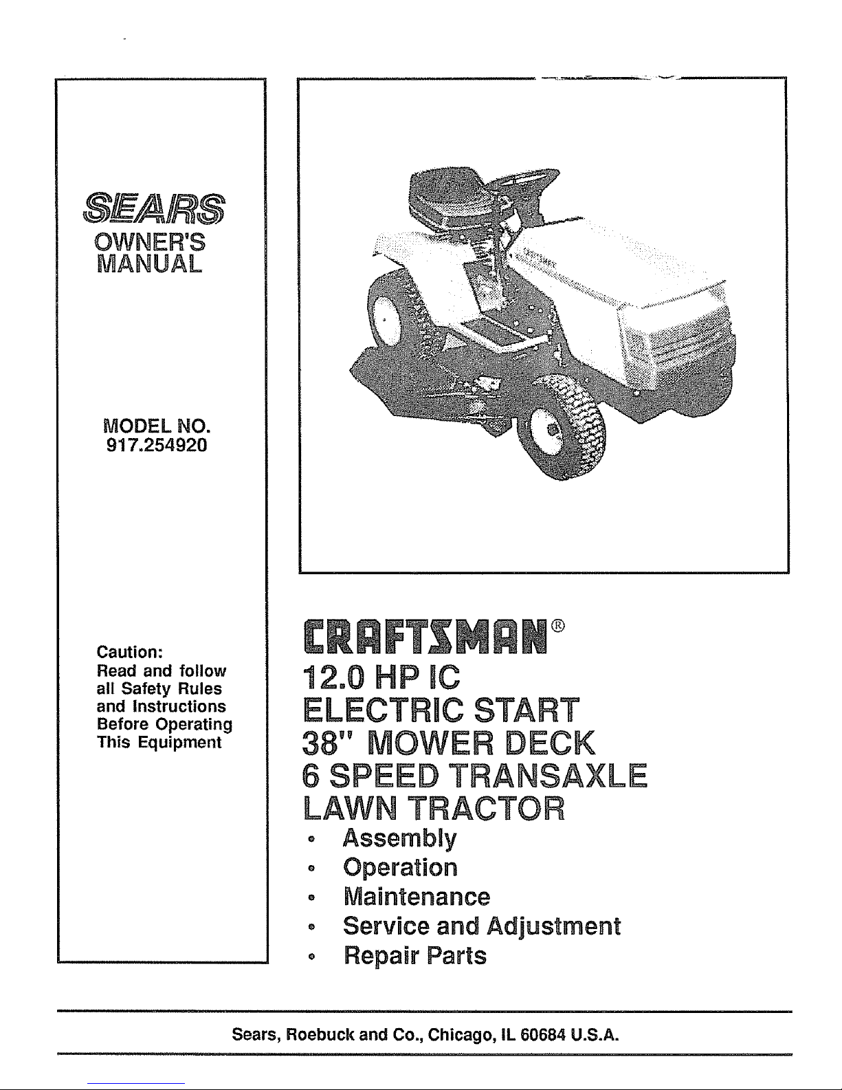
OWNER'S
MANUAL
MODEL NO.
917.254920
Caution:
Read and follow
all Safety Rules
and Instructions
Before Operating
This Equipment
®
Sears, Roebuck and Co., Chicago, IL 60684 U.S.A.
............................................. =l=.................... == ,,= ...... = .......
Page 2

LOOK FOR THIS SYMBOL TO POINT
OUT IMPORTANT SAFETY PRECAU-
TIONS. IT MEANS - ATTENTION! BE=
COME ALERT! YOUR SAFETY IS IN-
VOLVED.
CAUTION: LOOK FOR THIS WORD TO POINT OUT
IMPORTANT EQUIPMENT PRECAUTIONS.
NOTE: LOOK FOR THIS WORD TO POINT OUT IM-
PORTANT INFORMATION ABOUT THE OPERATION
AND PERFORMANCE OF YOUR TRACTOR
RULES FOR SAFE OPERATaON
WARNING: This unit is equipped with an internal combustion engine and should not be used on or neat any unimproved forest covered,
brush covered or grass covered land unless the engine's exhaust system is equipped with a spark attester meet ng app cab e ocal or area
laws (if any), If a spark arrester is used, it should be maintained in effective working order by the operator,. (See REPAIR PARTS for part
number dent f cation)
Inthe Slate of California the above is required by taw (Section 4442 of the California Public Resources Code), Other States may have similar
taws Federal laws apply on federal lands
1,, Know the controls and how to stop quickly° READ THIS
OWNER'S MANUAL and instructions furnished with attach-
ments.
2 Do not allow children to operate the machine, Do not allow
adults to operate it without proper instfuctiono
3 Do not carry passengers, Do not mow when children and
others are around
4. Always wear substantial footwear. Do not wear loose fitting
clothing that could get caught in moving parts
5 Keep your eyes and mind on your tractor, mower, and the
area being cut, Do not let other interests distract you,,
6 Do not attempt to operate your tractor or mower when not in
the driver's seat,.
7. Always get on or off your tractor from tile operator's left hand
side
8 Clear the work area of objects (wire, rocks, etc) which might
be picked up and thrown,,
9 Disengage aftattachment clutches before attempting to start
the engine.
10 Disengage power to attachments and stop the engine before
leaving the operator's position
11 Disengage power to mower, stopthe engine and disconnect
spark plug wire(s) from spark plug(s) before cleaning, making
an adjustment, or repair. Be careful to avoid touching hot
muffler or engine components
12 Disengage power to attachments when transporting or not i_,'
use,,
13. Take all possible precautions when leaving the vef_icle
unattended. Disengage the power take-off, lower the attach-
mef]ts, shift into neutral, set the parking brake, stop the
engine, and remove the key.
14. Do not stop or start suddenly when going uphill or downhill.
Mow up and down the face of slopes (not greater than 15°),
never across the face, Refer to page 47.
15. Reduce speed on slopes and make lures gradually toprevent
tipping or loss of control. Exercise extreme caution when
changing direction on slopes,
16, While going up or down slopes place gear shift control lever
n 1st gear position to negotiate the slope without stopping,
17 Never mow in wet or slippery grass when traction is unsure,
or at a speed wh ch could cause a skid,
18 Stay alert for holes in the terrain and other hidden hazards.
Keep away from drop-offs
19., Do not drive too close to creeks, ditches, and public high-
ways,
20, Exercise special care when mowing around fixed objects in
order to prevent the blades from striking them, Never delib-
erately run tractor or mower into or over any foreign objects.
21,, Never shift gears until tractor comes to a stop.
22 Never place hands or feet under the mower, in discharge
chute, or near any moving parts while tractor or mower Is
running,. Always keep clear of discharge chute.
23 Use care when pulling loads or using heavy equipment.
a Use only approved drawbat hitch points,.
b Limit loads to those you can safely control,
c., Do not turn sharply. Use care when backing.,
d,. Use counterweight or wheelweights when suggested in
owner's manual
24,. Watch out for traffic when crossing or near roadways
25_q using any attachments, never direct discharge of
materlz_ltoward bystanders nor allow anyone near the ve-
hicle while in operation
_6, Handle 9_soiine with care - it is highly flammable.
a. Use_pproved gaso!ine containers.
b. Never remove the fuel cap of the fuel tank or add
gasoline to a running or hot engine or an engine that has
not _een allowed to coo! for several minutes after run-
ning_ Never fill tank indoors_ Always clean up spitled
gasoline
c. O_en doors if the engine is run in the garage - exhaust
. f_mes are dangerous Do not run the engine indoors.
27 Ke_a the vehicle and attachments in good operating condi-
' tierS,and keep safety devices in place and working.,
28 t_.'eep all nuts, bolts, and screws tight to be sure the equip*
"ment is in safe working condition,,
2_ ,Never store the equipment with gasoline in the tank inside a
)uilding where fumes may reach an open flame or spark,
_Jlowthe engine to coo] before storing in any enclosure,.
30,. "o reduce fire hazard, keep the engine free of grass leaves,
excessive grease. Do not clean product while engine is
nnJng,
31, _ceptfor adjustments, DO NOToperate engine if aircleaner
eL.cover directly over carburetor air intake is removed
R_moval of such part could create a fire hazard.
32 Do\not operate without a muffler, or tamper with exhaust
system Damaged mufflers or spark attesters could create a
fire I_azard. Inspect periodically and replace if necessary.
33 The _,ehicle and attachments should be stopped and in-
specti_d for damage after striking a foreign object, and the
damag_eshould be repaired before restarting and operating
the equipment,,
34. Do nolchange the engine governor settings or overspeed the
engine; severe damage or k_jury may resulL
35 When using the vehicle with mower, proceed as follows:
a. Mow only in daylight or in good artificial lighL
b_ Silut the engine off when unclogging chute,,
c, Check the blade mounting bolts for proper tightness at
frequent intervals
36 Do not operate the mower without the entire grass catcher,
on mowers so equipped, or the deflector shield in place.
37, Disengage power to mower before backing up,,Do not mow
in reverse unless absolutely necessary and then only after
careful observation of the entire area behind the mower°
38, Under normal usage the gr ass catcher bag material issubject
to deterioration and wear. Itshould be checked frequently for
bag replacement Replacement bags should be checked to
ensure compliance with the o_iginal manufacturer's recom-
mendations or specifications,.
2
Page 3
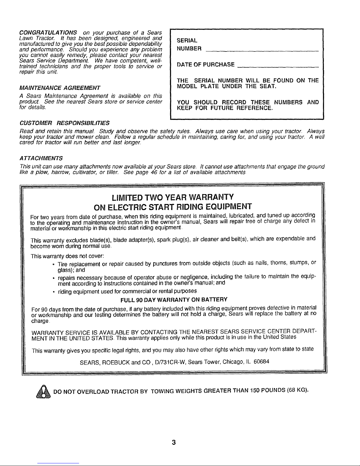
CONGRATULATIONS on your purchase of a Sears
Lawn Tractor. It has been designed, engineered and
manufactured to give you the best possible dependability
and performance. Should you experience any problem
you cannot easily remedy, please contact your nearest
Sears Service DepartmenL We have competent, well-
trained technicians and the proper tools to service or
repair this unit.
MAINTENANCE AGREEMENT
A Sears Maintenance Agreement is available on this
PforOduCt.See the nearest Sears store or service center
r details_
SERIAL
NUMBER
DATE OF PURCHASE
THE SERIAL NUMBER WILL BE FOUND ON THE
MODEL PLATE UNDER THE SEAT.
YOU SHOULD RECORD THESE NUMBERS AND
KEEP FOR FUTURE REFERENCE.
CUSTOMER RESPONSIBILITIES
Read and retain this manual. Study and observe the safety rules_ Always use care when using your tractor. Always
keep your tractor and mower clean.. Follow a regular schedule in maintaining, caring for, and using your tractor. A well
cared for tractor will run better and last longer.
A TTA CHMENTS
This un# can use many attachments now available at your Sears store. It cannot use attachments that engage the ground
like a plow, harrow, cultivator, or tiller. See page 46 for a list of available attachments
LIMITED TWO YEAR WARRANTY
ON ELECTRIC START RIDING EQUIPMENT
For two years from date of purchase, when this riding equipment is maintained, lubricated, and tuned up according
to the operating and maintenance instruction in the owner's manual, Sears will repair free of charge any delect in
material or workmanship in this electric start riding equipment
This warranty excludes b_ade(s), blade adapter(s), spark p]ug(s), air cteaner and belt(s), which are expendable and
become worn during normal use.
This warranty does not cover:
. Tire replacement or repair caused by punctures from outside objects (such as nails, thorns, stumps, or
glass); and
• repairs necessary because of operator abuse or negligence, inckJding the failure to maintain the equip-
ment according to instructions contained in the owner's manual; and
- riding equipment used for commercial or rental purposes
FULL 90 DAY WARRANTY ON BATTERY
For 90 days from the date of purchase if any battery included with this riding equipment proves defective in material
or workmanship and our testing determines the battery w not hold a charge, Sears will replace the battery at no
charge
WARRANTY SERVICE IS AVAILABLE BY CONTACTING THE NEAREST SEARS SERVICE CENTER DEPART-
MENT IN THE UNITED STATES. This warranty applies only while this product is in use in the United States
This warranty gives you specific legal rights, and you may also have other rights which may vary from state to state
SEARS, ROEBUCK and CO, D/731CR-W, Sears Tower, Chicago, IL 60684
n._l,i iiiii i i i.. iii ill i , qlll.ii iHrlll ii .......................
ii,, ,lllll i,,
_DO NOT OVERLOAD TRACTOR BY TOWING WEIGHTS GREATER THAN 150 POLtNDS (68 KG).
3
Page 4
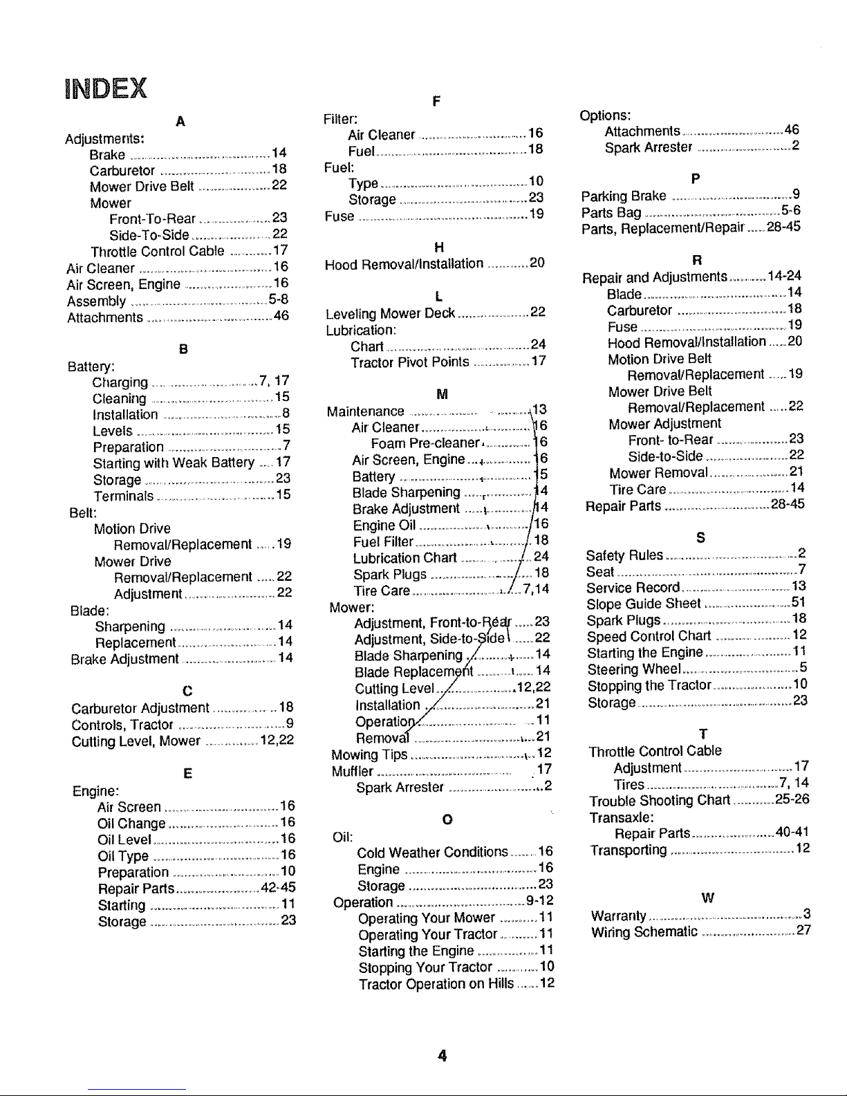
INDEX
A
Adjustments:
Brake ................................................14
Carburetor. ...................................18
Mower Drive Belt ........................22
Mower
Front-To-Rear .........................23
Side-To-Side .........................22
Throttle Control Cable ...............17
Air Cleaner ...........................................16
Air Screen, Engine ............................16
Assembly ...............................................5-8
Attachments ............................................46
B
Battery:
Charging ....................................7, 17
Cleaning .............................................15
Installation ...........................................8
Levels ..............................................15
Preparation .......................................7
Starting with Weak Battery .......17
Storage ...........................................23
Terminals ...................................15
Belt:
Motion Drive
RemovalfReplacement ......t9
Mower Drive
Removal/Replacement ......22
Adjustment ..................................22
Blade:
Sharpening ..................................14
Replacement ....................................14
Brake Adjustment ..................................14
C
Carburetor Adjustment ...................18
Controls, Tractor ....................................9
Cutting Level, Mower ....................12,22
E
Engine:
Air Screen ..................................... t 6
Oil Change ...................................16
Oil Level .........................................16
Oil Type ...............................................16
Preparation ....................................10
Repair Paris ..........................42-45
Starting .................................................11
Storage .............................................23
F
Filter:
Air Cleaner ...................................16
Fuel .....................................................18
Fuel:
Type ...................................................10
Storage ..............................................23
Fuse ............................................................t9
H
Hood Removal/Installation .............20
L
Leveling Mower Deck ......................22
Lubrication:
Chart ......................................................24
Tractor Pivot Points ..................17
M
Maintenance ......................................;13
Air Cleaner ......................,.................16
Foam Pre-cteaner ..................6
Air Screen, Engine...._.............. 6
Battery ........................4..................5
Blade Sharpening .......,............. 4
Brake Adjustment ......_..............o_4
Engine Oil .......................,............/1/'_6
Fuel Filter ........................................._/..18
Lubrication Chart ............... ../..24
Spark Plugs ....................................../t18
Tire Care ....................................,./_ 7,14
Mower:
Adjustment, Front-to-Bier/ .....23
Adjustment, Side-to-_ide I......22
Blade Sharpening ./ ........._.......14
Blade Replacem_ht ...............t......14
Cutting Level _./_.......................12,22
/
Operatio .......................................11
Ben}ova( .....................................,.._21
Mowing Tips ............................................_..12
Muffler. ..................................................17
Spark Arrester. ..................................2
O
Oil:
Cold Weather Conditions ............16
Engine ................................................16
Storage ........................................23
Operation .......................................9-12
Operating Your Mower ..............11
Operating Your Tractor ..............11
Starting the Engine ....................11
Stopping Your Tractor .............10
Tractor Operation on Hills ...... 12
Options:
Attachments ...................................46
Spark Arrester ................................2
P
Parking Brake ...........................................9
Paris Bag .................................................5-6
Parts, Replacement/Repair ......28-45
R
Repair and Adjustments ..............14-24
Blade .....................................................14
Carburetor ....................................18
Fuse .......................................................19
Hood Remova!/installation .....20
Motion Drive Belt
Removal/Replacement ......19
Mower Drive Belt
RemovallReplacement .....22
Mower Adjustment
Front- to-Rear .........................23
Side-to-Side ...........................22
Mower Removal ........................21
Tire Care ...........................................14
Repair Parts ...................................28-45
S
Safety Rules ................................................2
Seat ..........................................................7
Service Record .....................................13
Slope Guide Sheet ..............................51
Spark Plugs ...........................................18
Speed Control Chart ..................... 12
Starting the Engine ..............................1t
Steering Wheel .........................................5
Stopping the Tractor ...................... 10
Storage .....................................................23
T
Throttle ConLrol Cable
Adjustment ......................................17
Tires ............................................7, 14
Trouble Shooting Chart ............25-26
Transaxle:
Repair Parts ..........................40-41
Transporting ..........................................12
W
Warranty ......................................................3
Wiring Schematic ................................27
4
Page 5

ASSEMBLY
To assemble tractor you will need:
(2) 7116"wrenches Tire Pressure Gauge
(1) 1t2"wrench Screwdriver
(2) 9!16" wrenches Utility Knife
(1) 3/4" wrench 5/16" Wrench
Take all of the Items out of the box. The box contains the Items shown below. Open the parts bag and check the
contents (see page 6).
D
C
G
A
B
F
ao Seat d Battery Acid
bo Steering wheel e. Owner's Manual
c, Battery f, Parts Bag
g Steering Boot
i
Parts bag contents not shown full size
___ fill!lltlltltl!!iltlltlfilll!!lllllllltlltlll Ill!!l
(2) Battery Carriage Bolts - 1/4 x 20 x 7 1/2
Terminal Guard
t5 ° Slope Instruction
(2) Keys
Steering Wheel Adapter
Steering Wheel Insed
NOTE: RIGHT HAND(R.H) AND LEFT HAND (L.H.) ARE
DETERMINED FROM OPERATOR'S POSITION
WHILE SEATED ON THE TRACTOR°
The operation of any tractor can result in foreign objects
thrown into the eyes, which can result in severe eye dam-
age. Always wear safety glasses or eye shields before start-
ingyour tractor and while moving° We recommend Wide Vi-
sion Safety Mask for over the spectacles or standard safety
glasses, available at Sears Retail or Catalog Stores°
5
Page 6
ASSEMBLY
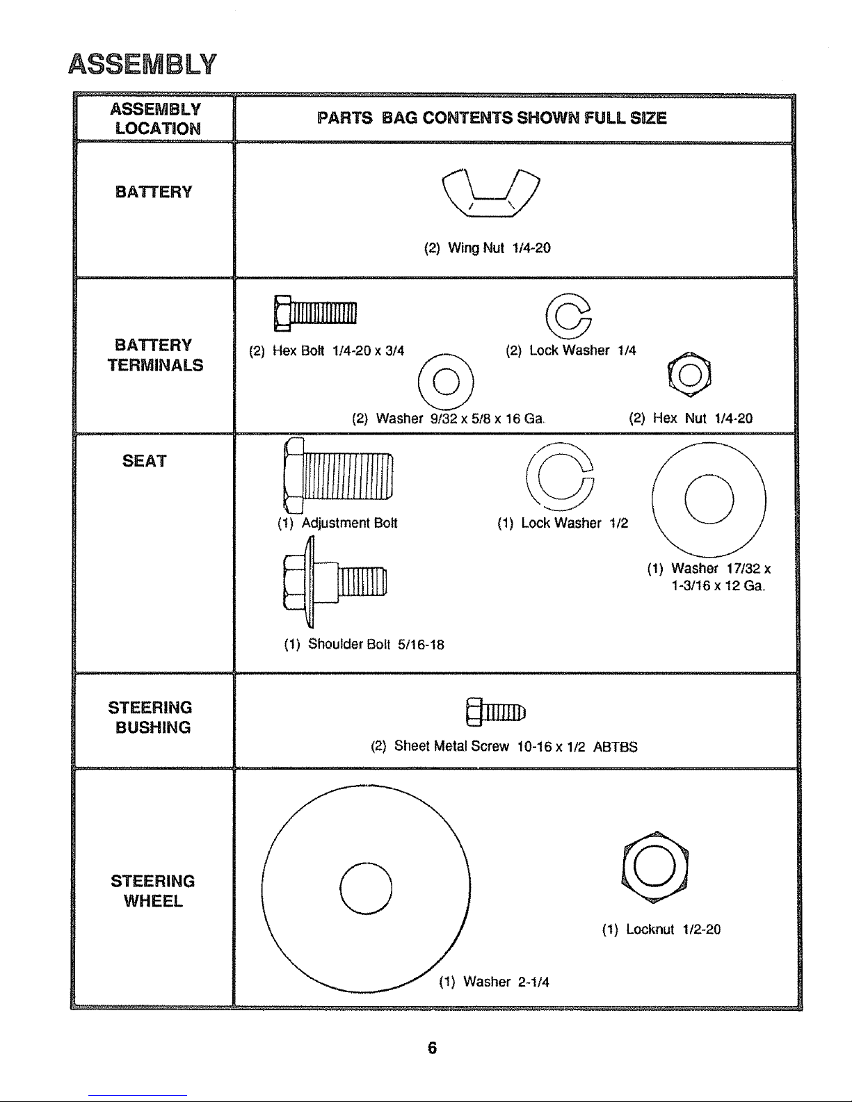
ASSEMBLY
PARTS BAG CONTENTS SHOWN FULL SaZE
LOCATION
,i,,, _........ __.. i , ,i,, i,,,11 i, ,.........
BA'I-I'ERY
BATTERY
TERMINALS
SEAT
STEERING
BUSHING
STEERING
WHEEL
_IIIIHIII_
(2) Hex Bolt 1/4-20 x 3/4
(2) Wing Nut 1/4-20
©
(2) Washer 9/32 x 5/8 x 16 Ga,.
©
(2) Lock Washer 1/4
©
(2) Hex Nut 1/4-20
F-
IIlliI
_LJ
(t) Adjustment Bot (1) Lock Washer t/2
I
,-- _ ]']T[Tm-I1 (1) Washer 17/32 x
_ 1-3/16 x 12 Gao
1_--
r
(1) Locknut 1/2-20
(1) Shoulder Bolt 5/16-18
(2) Sheet Metal Screw 10-16 x 1/2 ABTBS
, @ !
___(t) Washer 2-1/4
6
Page 7

1. Prepare Battery
WEAR EYE AND FACE SHIELD.
WASH HANDS OR CLOTHING IMMEDI-
ATELY IF ACCIDENTALLY INCONTACT
WITH BATTERY ACID.
DO NOT SMOKE. FUMES FROM
CHARGED BATTERY ACID ARE EX-
PLOSIVE.
READ THE INSTRUCTIONS INCLUDED
WITH THE BATTERY VENT CAPS IN
THE BAG OF PARTS. ALWAYS WEAR
GLOVES, CLOTHING AND GOGGLES
TO PROTECT YOUR HANDS, SKIN AND
EYES.
Fill and charge battery (before installing) NOTE: SEE DE-
TAILED INSTRUCTIONS PACKAGED WITH BATTERY
VENT CAPS FOUND IN BAG OF PARTS.
a Fill each cell with battery acid. Add the acid until it
reaches the bottom of the vent tubes (Fig. 1)oDo not
add the acid beyond this level or the additional acid
can come out when the battery is charged,
b. After cells are filled, tilt battery from side to side to
release air bubbles
c. Allow battery to stand and settle for at least thirty
minutes. Ifthe level of acid falls below the point de-
scribed in step (a), add more acid until the correct
level isreached Install the battery caps, found inthe
bag of parts, to cove rthe vent tubes_Wash thetop of
the battery with water to remove any acid, then wipe
dry.
d. Check battery case for leakage to make sure thai no
damage has occurred in handling,
e, Neutralize excess battery acid for disposal by add-
ing it to 2 gallons (7Itres) of water in a five gallon (20
litres) plastic container, Stir with awooden or plastic
paddle while adding baking soda until the addition of
more soda causes no more foaming.
fo It is recommended that the battery be charged be-
fore use. Use a 12 volt battery charger, Charge bat-
ten/at a rate of 6 amperes for 1 hour. NOTE: OB-
SERVE SAFETY PRECAUTIONS, LISTED IN BOX
ABOVE, REQUIRED FOR BATTERY CHARGING.
Check the acid level after the battery is charged. If
the acid has fallen below the correct level, add dis-
tilled or iron free water.
2. Unpack Tractor
a Cut down fourcorners of the carton with utility knife
and fold down sides.
b Disengage parking brake and position front wheels
straight ahead (see page 9)
c, Install steering wheel
1, Slide the steering bushing over the steering
shaft (Fig,, 2)
2. Position steering shaft forward until screw holes
in dash line upwith steering bushing. Installtwo
(2) screws (Fig° 2).
3o Position steering boot over steering shaft
4. Place bottom of steering boot over two slots in
dash (Fig,,2).
ASSEMBLY
CUT AWAY VIEW .......
...... ] Ir .,BATTERY
_,Z VENT TUBE
II III 11"I/,,V,L
I::l v'_ _J _ v_ r_ BATTERY
H _ _ _._1'I ~._~:-:-:_ CELL
1/2" NUT
2 - 1/4" DIA. WASHERs...
FIGURE 1
j_,_-_-STEERING
WHEEL
ADAPTER
STEERING
BOOT
STEERING
BUSHING
STEERING SHAFT
(REC'Do POSITION)
STEERING SHAFT
(INST. POSITION)
FIGURE 2
7
5. Push steering boot down into aligning slots on
dash.
6 Place steering wheeladapteron steering shaft
7. With front wheels pointed straight ahead, place
steering wheel on steering wheel adapter. Bars
of steering wheel should point straight across
tractor.
Page 8
ASSEMBLY
SEAT
SEAT PAN
SHOULDER
BOLT
ADJUSTMENT
BOLT LOCK
WASHER
FIGURE3
FLAT
WASHER
POSITIVE WASHER
WASHER
HEXBOLTS
POSITIVE
CABLE
(RED)
NEGATIVE
_AL
NEGATIVE
CABLE
(BLACK)
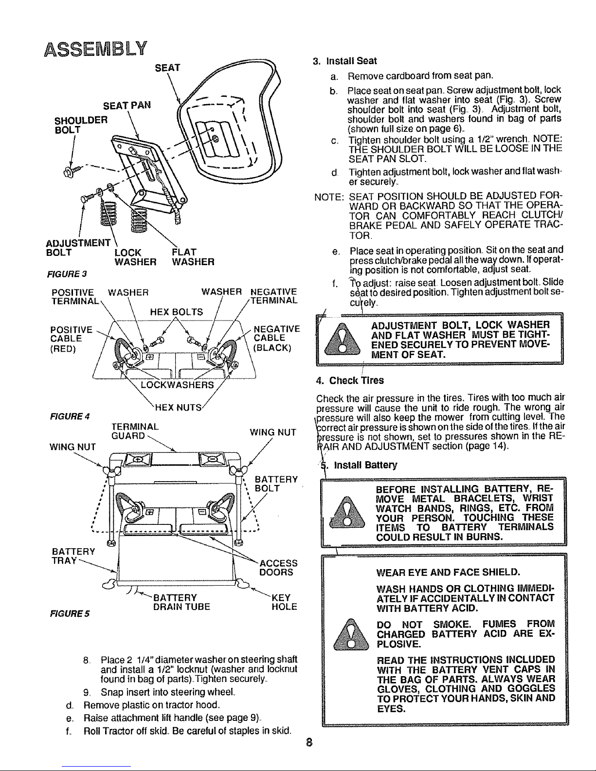
3, Install Seat
d
NOTE:
a. Remove cardboard from seat pan,.
b. Place seat on seat pan. Screw adjustment bolt, lock
washer and flat washer into seat (Fig.. 3). Screw
shoulder bolt into seat (Fig 3). Adjustment bolt,
shoulder bolt and washers found in bag of parts
(shown full size on page 6).
c. Tighten shoulder bolt using a 1/2" wrench NOTE:
THE SHOULDER BOLT WILL BE LOOSE IN THE
SEAT PAN SLOT..
Tighten adjustment bolt, lock washer and flat wash-
er securely_
SEAT POSITION SHOULD BE ADJUSTED FOR-
WARD OR BACKWARD SO THAT THE OPERA-
TOR CAN COMFORTABLY REACH CLUTCH/
BRAKE PEDAL AND SAFELY OPERATE TRAC-
TOR.
eo Place seat in operating position.. Sit on the seat and
press clutch/brake pedal all the way down, !foperat-
ing position is not comfortable, aaiusl sere,.
FIGURE 4
WING NUT
HEX NUTS
TERMINAL
WING NUT
BATTERY
FIGURE 5
BATTERY
BOLT
DOORS
"BATTERY _'_'_KEY
DRAIN TUBE HOLE
d.
eo
f.
8. Place 2 1/4"diameterwasheron steering shaft
and install a I/2" locknut (washer and Iocknut
found in bag of parts)..Tighten securely,.
9o Snap insert into steering wheel
Remove plastic on tractor hood..
Raise attachment lift handle (see page 9)..
Roll Tractor off skid,. Be careful of staples in skid.
4. Check Tires
Check the air pressure in the tires, Tires with too much air
_ressure will cause the unit to ride rough. The wrong air
_ressure will also keep the mower from cutting level. The
;orrect air pressure isshown on the side of the tires° tf the air
)ressure is not shown, set to pressures shown in the RE-
'AtR AND ADJUSTMENT section (page 14)o
. Install Battery
BEFORE INSTALLING BATTERY, RE-
MOVE METAL BRACELETS, WRIST
WATCH BANDS, RINGS, ETC. FROM
YOUR PERSON. TOUCHING THESE
ITEMS TO BATTERY TERMINALS
COULD RESULT IN BURNS.
WEAR EYE AND FACE SHIELD.
WASH HANDS OR CLOTHING IMMEDI-
ATELY IF ACCIDENTALLY IN CONTACT
WITH BATrERY ACID.
DO NOT SMOKE. FUMES FROM
CHARGED BATTERY ACID ARE EX-
PLOSIVE.
READ THE INSTRUCTIONS INCLUDED
WITH THE BATTERY VENT CAPS IN
THE BAG OF PARTS. ALWAYS WEAR
GLOVES, CLOTHING AND GOGGLES
TO PROTECT YOUR HANDS, SKIN AND
EYES.
8
Page 9
ASSEMBLY
a., Lift seat (Fig, 3),
b Lower battery into fender well with battery terminals
toward front of tractor (Fig, 4), Make sure battery
rests in battery tray (Fig. 5)°
NOTE: BE SURE BATTERY DRAIN TUBE IS SECURELY
ATTACHED TO BATTERY TRAY DRAIN (Fig, 5)
POSITIVE TERMINAL MUST BE CON-
NECTED FIRST TO PREVENT SPARKS
FROM ACCIDENTAL GROUNDING.
c, Connect RED battery cable to positive (+) battery
terminal with hex bolt, flat washer, lock washer and
hex nut (shown full size on pg 6) found in bag of
parts, Tighten securely with two 7/16 wrenches
(Fig. 4).
io
J,,
CAUTION:
d Connect BLACK ground cable to negative (-) bat-
tery terminal with remaining hex bolt, flat washer,
lock washer and hex nut (shown full size on pg 6)
found in bag of parts,,Tighten securely (Fig 4).
e To prevent corrosion, apply grease to the battery
terminals after installing cables_
f, Slide two battery bolts through terminal guard and
start the wing nuts onto the threads (Fig 5).
g Position terminal guard over battery as shown (Fig
5) and align bolt heads with key holes next to battery
tray (Fig5),
h Lower bolt heads into key holes and slide square
shafts of bolts into slots of key holes (Fig 5)
Tighten wing nuts,
Close terminal access doors,
DO NOT START ENGINE UNTIL YOU HAVE
REVIEWED THE OPERATION SECTION OF
THIS MANUAL.
LIFT LEVER PLUNGER
OPERATION
ATTACHMENT
CLUTCH
IGNITION
ATTACHMENT
LIFT LEVER
LIGHT SWITCH
ADJUST-
MENT SLOTS
CONTROL
CLUTCH/BRAKE
PEDAL
MOWER DECK
HEIGHT
ISTMENT
POSITIONING
PARKING BRAKE
GEARSHIFT LEVER
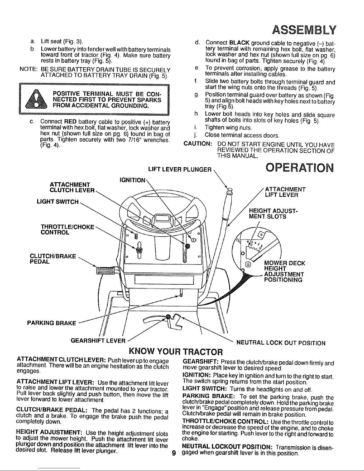
KNOW YOUR
ATTACHMENTCLUTCH LEVER: Push lever upto engage
attachment There will be an engine hesitation as the clutch
engages,,
ATTACHMENT LIFT LEVER: Use the attachment litt lever
to raise and lower the attachment mounted to your tractor.
Pull lever back slightly and push button, then move the lift
lever forward to lower attachment.
CLUTCH/BRAKE PEDAL: The pedal has 2 functions; a
clutch and a brake. To engage the brake push the pedal
completely down°
HEIGHT ADJUSTMENT: Use the height adjustment slots
to adjust the mower height. Push the attachment lift lever
plunger down and position the attachment lift lever into the
desired sloto Release lift lever plunger,,
NEUTRAL LOCK OUT POSITION
TRACTOR
GEARSHIFT: Press the clutchJbrakepedal down firmly and
move gearshill lever to desired speed,
IGNITION: Place key in ignition and turn to the right to start.
The switch spring returns from the start position
LIGHT SWITCH: Turns the headlights on and off.
PARKING BRAKE: To set the parking brake, push the
clutch/brake pedal completely down. Hold the parking brake
lever in Engage position and release pressure from pedal.
Clutch'brake pedal will remain in brake position.
THROTTLEIGHOKE CONTROL: Use the throttle control to
increase or decrease the speed of the engine, and to choke
the engine for starting, Push lever to the right and forward to
choke°
NEUTRAL LOCKOUT POSITION: Transmission is disen-
gaged when gearshift lever is in this position,
Page 10

OPERATmON
AIR SCREEN
FUEL FILLER
CAP
FUEL TANK
/
FIGURE 6
OIL FILLER
CAP/DIPSTICK
1
OIL DRAIN
1. Stopping Your Tractor
NOTE: REMOVE KEY WHEN LEAVING TRACTOR TO
PREVENT UNAUTHORIZED USE:
a.. Push clutch-brake pedal intofull "BRAKE" position.
Keep your foot on pedal (Fig. 7).
b. Place attachment clutch lever in "DISENGAGED"
position
co Move gearshift lever to "NEUTRAL" position,,
d, Lift up to place parking brake in "ENGAGED" posi-
tion (Fig. 10) and release pressure from clutcW
brake. Pedal should remain in "BRAKE" position.,
e,. Move throttle control to "S" (slow) position.
f. Turn ignition key to "OFF" position., Never use choke
to stop engine.
2. Preparing the Engine
LEARN TO STOP YOUR TRACTOR BE-
FORE ATTEMPTING TO START THE EN-
GINE.
a, This engine has been shipped filled with summer
weight oil (For cold weather operation see chart
page 16). Check engine oil level. Refer to REPAIR
AND ADJUSTMENT section (page 16)o
IGNITION KEY Changing oil after the first two hours (or two mowings) will
help eliminate break-in residue which might be damaging to
ATTACHMENT CLUTCH LEVi_R yo_r engine,
"ENGAGED" POSITION b.. Fil! fue! tank (Fig. 6). Use fresh, clean, regular un-
leaded gasoline° Capacity is 5 quarts (4.7 titres)..
"DISENGAGED_
POSITION
\NOTE: FRESH, CLEAN WINTER GRADE FUEL MUST
BE USED TO INSURE GOOD COLD WEATHER
STARTING
SWITCH
THROTTLE
CONTROL
PARKING
BRAKE
POSITION
GEARSHIFT
LEVER
FILL TO BOTTOM OF GAS TANK
FILLER NECK. DO NOT OVERRLL
WIPE OFF ANY SPILLED OIL OR FUEL.
DO NOT STORE, SPILL OR USE GASO-
LINE NEAR AN OPEN FLAME.
CAUTION:
EXPERIENCE INDICATES THAT ALCOHOL
BLENDED FUELS (CALLED GASOHOL OR
USING ETHANOL OR METHANOL) CAN AT-
TRACT MOISTURE WHICH LEADS TO
SEPARATION AND FORMATION OF ACIDS
DURING STORAGE. ACIDIC GAS CAN
DAMAGE THE FUEL SYSTEM OF ANY EN-
GINE WHILE IN STORAGE
"CLUTCH" _.._j_
POSITION, CLUTCH1BRAKE
DRIVE POSITION!
"BRAKE"
POSITION
FIGURE 7
10
TO AVOID ENGINE PROBLEMS, THE FUEL
SYSTEM SHOULD BE EMPTIED BEFORE
STORAGE FOR 30 DAYS OR LONGER.
DRAIN THE GAS TANK, START THE EN-
GINE AND LET IT RUN UNTIL THE FUEL
LINES AND CARBURETOR ARE EMPTY.
USE FRESH FUEL NEXT SEASON_ SEE
STORAGE INSTRUCTIONS FOR ADDI-
TIONAL INFORMATION.,
NEVER USE ENGINE OR CARBURETOR
CLEANER PRODUCTS IN THE FUEL TANK
OR PERMANENT DAMAGE MAY OCCUR.
Page 11

3. Starting the Engine
a. Move throttle control lever (Fig 7) past "FAST" to
the "CHOKE" position
bo Fully depress clutch/brake pedal
c_ Turn ignition key to "START" and release key as
soon as engine starts
OPERATWON
AI-rACHMENT CLUTCH
LEVER "ENGAGED"
POSITION LIFT LEVER
ATTACHMENT CLUTCH LIFT LEVER "HIGHEST"
LEVER "DISENGAGED" PLUNGER POSITION
POSITION
CAUTION: DO NOT RUN STARTER CONTINUOUSLY
FOR MORE THAN FIFTEEN SECONDS PER
MINUTE,
d If engine does not start after four or five tries, move
throttle control lever to FAST" position, wait a few
minutes and try again If the engine does not start
alter four or five more tries, see the
TROUBLESHOOTING Chart (page 25),
e After the engine starts move throttle control lever
slowly to the "SLOW" position.
f_ To start a hot engine move the throttle control lever
to a position between "FAST" and "SLOW"_
READ THE "RULES FOR SAFE OPERA-
TION" CAREFULLY BEFORE OPERAT-
ING YOUR MOWER.
&
DO NOT OVER LOAD TRACTOR BY
TOWING WEIGHTS GREATER THAN
150 POUNDS (68 KG).
ALWAYS WEAR SUBSTANTIAL FOOT-
WEAR AND AVOID LOOSE FITTING
CLOTHING THAT COULD GET
CAUGHT IN MOVING PARTS.
DO NOT OPERATE THE MOWER WITH-
OUT EITHER THE ENTIRE GRASS
CATCHER, ON MOWERS SO
EQUIPPED, OR THE DEFLECTOR
SHIELD IN PLACE.
CAUTION
TO AVOID INJURY
1. Read owner's manual
2. Know location and function of all controls,
3. Keep guards, safety shield and switches in place and
working.
4. Remove objects that can be thrown by blades,
5, Do not mow when children and others are around,
6 Never carry children or passengers
7., Always look behind machine before backing,
8o Do not mow where machine can tip or slip.
9o tf machine stops going uphill, stop blades and back
slowly down.
10. Be sure blades and engine have stopped before placing
hands or feet near the blades.
11, Remove key when leaving machine.
11
POSITION
R.H. RUNNER
DISCHARGE
GUARD RGURE8
WHEN PARKING BRAKE iS ENGAGED,
MAKE SURE IT WILL KEEP TRACTOR
FROM MOVING.
NEVER PLACEYOURHANDS OR FEET
INORUNDERANYPOWEREDATIrACH -
MENT OR NEAR ANY MOVING PART
WHILE TRACTOR OR ANY POWERED
ATTACHMENTIS RUNNING.
4. Operating Your Lawn Tractor and Mower
NOTE: THIS TRACTOR IS EQUIPPED WiTH AN OPERA-
TOR PRESENCE SENSING SWITCH. ANY AT-
TEMPT BY THE OPERATOR TO LEAVE THE
SEAT WITH THE ENGINE RUNNING AND THE
ATTACHMENT CLUTCH LEVER ENGAGED WILL
SHUT OFF THE ENGINE.
CAUTION: DO NOT ADD ADDITIONAL WEIGHT
TO THE TRACTOR OTHER THAN THE OP-
TIONAL WHEEL WEIGHTS, EXCESSIVE
WEIGHT MAY OVERLOAD AND DAMAGE THE
TRANSAXLE
a. Depress lift lever plunger and move the attachment
lift lever to the highest position. See Fig., 8
b Start the engine (See Starting the Engine).
c, Move the throttle lever to mid range position. Fully
depress clutch/brake pedal. Select a low (Ist or2nd)
gear until you become more familiar with the opera-
tion of the unit,
Page 12

OPERATmON
,J,J
FIGURE 9
, , , =,==! ....................... I,IH,
SPEED SELECTION GUIDE
, ,1 ,, ,1,1,11,,111,11,11
GEARSHIFT THROTTLE
2or3
FUNCTION
Normal
Mowing
Heavy Mowing t or 2
Snow Blowing
Snow Blade
Transport
1
2
4-6
FAST
SLOW-
FAST
d,
e,
f,_
g.
h.
io
CAUTION:
Slowly release clutch/brake pedal and proceed to
the mowing area.
Stop the unit, then select a mowing speed. (See
Speed Selection Guide, above)..
Move throttle lever to flail ttlrottle and slowly move
attachment clutch lever to engaged position, Fig, 8.
Slowly release clutch/brake pedal.
Move throttle lever to fast position°
Observe height of cut and readjust as desired (see
page 9).
BEFORE YOU MOVE THE GEARSHIFT
LEVER, COME TO A COMPLETE STOP.
FAILURE TO DO SO CAN RESULT IN GEAR
BOX DAMAGE
5. Mowing Tips
NOTE: TIRE CHAINS CANNOT BE USED WITH THE
MOWER ATTACHED.
12
a,, Mower should be adjusted properly front to back
and side to sidefor good mowing performance. Re-
fer to REPAIR AND ADJUSTMENT section (page
22),.
b_ Use the runner on the R.H side as a guide; the
blade cutsapproximately an inch (2,.54cm)outside
the runner (Fig, 8)°
c. Ddve sothat clippings are discharged onto the area
that has been cuL Have the cut area to the rightof
the machine. This willresult ina more even distribu-
tionof clippings and more uniform cutting°
d. When mowing large areas (Fig,,9), start byturning
totile rightso that the clippingswill discharge away
from shrubs, fences, driveways, etc. After two or
three rounds, mow in the opposite direction making
lefthand turns until finished°
e._ If grass is extremely tall, it should be mowed twice.
The first time cut relatively high; the second time to
the desired heighL
fo The left hand side of mower should be used for trim-
ruing
_i See Speed Selection Guide.
Do not mow tall, dry (brown) grass over 6 inches
(1524 cm) tall It is a fire hazard.
6, Operating the Tractor on Hills
DO NOT DRIVE UP OR DOWN HILLS
WITH SLOPES GREATER THAN 15°
AND DO NOT DRIVE ACROSS ANY
SLOPE= REFER TO PAGE 47.
\ ...............
a
b.
C.
Move gearshift lever to "lst" gear before starting up
_ordown hills.
A_OID STOPPING OR SHIFTING ON HILLS.
If slowing is necessary, move throttle control lever
to slower position,
LEAVE ENOUGH ROOM WHEN STOP-
PING AND STARTING TO ALLOW
SLIGHT TRACTOR ROLL DOWNHILL
AS CLUTCH/BRAKE PEDAL MOVES
THROUGH CLUTCH POSITION.
d. If stopping is absolutely necessary, push clutch/
brake pedal quickly to brake position.
e_ To restart tractor movement, make sure tractor is in
the lowest speed range ("1st" Gear) and release
clutch/brake pedal SLOWLY.
f., Make all turns gradually_
7. Transporting Your Tractor
For pushing or towing your rtractor, place gearshift lever
in "N" position. Do not tow or push at more than 6 MPH
(9,,7 KPH)o
Page 13

Tokeep yourtractor running better and longer,
perform necessary service using the follow-
ing maintenance schedule:
WITH EVERY MOWING
1o Make sure all nuts on bolts are tight and cotter pins and
retainer springs are secure,
2 Observe al! safety precautions.
3o Keep tractor well lubricated (refer to page 24).
4. Make sure areas around muffler, engine and mower
deck are clean and free of debris buildup.
MAINTENANCE
BEFORE MAKING ANY INSPECTION, AD-
JUSTMENT, OR REPAIR:
1. PUSH TRACTOR CLUTCH/BRAKE
PEDAL COMPLETELY DOWN,
2._ MOVE GEAR SHIFT CONTROL LEVER
TO NEUTRAL POSITION.
3. PLACE PARKING BRAKE IN "EN-
GAGED" POSITION. REMOVE FOOT
FROM PEDAL.
4. DISENGAGE ATTACHMENT CLUTCH
LEVER_
5. SHUT OFF THE ENGINE.
6. MAKE ABSOLUTELY SURE THE
BLADES AND ALL MOVING PARTS
HAVE COMPLETELY STOPPED,,
7. REMOVE IGNITION KEY,,
8. DISCONNECTTHE SPARK PLUG WIRE
FROM THE SPARK PLUG AND KEEP
WIRE AWAY FROM THE SPARK PLUG
TO PREVENT INJ URY FROM ACCIDEN*
TAL STARTING. BE CAREFUL TO
AVOID TOUCHING HOT ENGINE OR
MUFFLER COMPONENTS.
SERVICE RECORD
FILL IN DATES
AS YOU COMPLETE
REGULAR SERVICE
Check Engine Oil Level
Change Engine Oil
Check Brake Operation
Check Tire Pressure
Sharpen Mower Blades
Clean Air Screen
v' _,2
J
.....it' ....... V'
v"
v'
v'
Clean Air Cleaner
Lubricate Pivot Points
Check Battery Level/Recharge
Clean Battery and Terminals
Inspect MufflertSpark Arrester
Clean Engine C0o!!ng System =
Replace Air Cleaner paper Cartridge
Replace Spark Plug
Replace Fuel Filter
Check Valve Clearance
Check for Loose Fasteners
i...... L
i
iCle,anmg (S,ee Maintenance)
1- Change moreoften when operating under a heavy load or in high ambient temperatures
2- Service more oftenwhen operating indirtyordusty conditions
3- Sharpenbladesmore oftenwhen mowing insandysol!
J
v'
!3
Page 14

REPAIR AND ADJUSTMENT
TH PARKING
ENGAGED)
BRAKE ROD
DISC BRAKE
FIGURE 10
NUT "A"
_T NUT
ING ARM
;EMBLY
LC
HEX BOLT GR.
FIGURE 11
HUB CAP WASHERS
KLIP RING
FIGURE 12
SQUARE KEY
(REAR TIRE ONLY)
A GRADE 5 HEAT TREATED
BOLT CAN BE IDENTIFIED BY
THREE LINES ON THE BOLT
HEAD AS SHOWN AT LEFT.
14
1. Brake Adjustment
This tractor is equipped with an adjustable brake system
mounted on the rightside of the transaxle (Fig. 10).
IF TRACTOR REQUIRES MORE THAN
SIX FEET (1.8 METERS) STOPPING
DISTANCE IN HIGHEST GEAR, THEN
BRAKE MUST BE ADJUSTED.
a. Depress clutch/brake pedal and engage parking
brake,.
b_ Measure distance between brake operating arm
and nut "A" on brake rod,.
c. If distance is other' than 1-1/2" (3.8t cm), loosen
jam nut (Fig. 10) and turn nut until distance be-
comes 1-1/2" (3,,8t cm). Retighten jam nut against
nut "A",
Road test tractor for'proper stopping distance as stated
above_ Readjust if necessary= If stopping distance is still
greater than 6 feet (1,8 meters) in highest gear, further
maintenance is necessary, Contact your local Sears Sew-
ice Center
2. Tire Care
a Maintain tire pressure in front at 14 PSI (1Kg/cm 2)
and rear tires at 10 PSI (0.7 Kg/cm_),.
b. Keep thes free of gasoline, oil, or insect control
chemicals which can harm rubber,
c. Avoid stumps, stones, deep ruts,sharp objects and
other hazards that may cause tire damage.
d Removing wheel for tire repair (Fig, 12),
1_ Block up axle securely.
2. Remove hub cap, klip ring and washer to allow
wheel removal (rear wheel contains a square
key- Do Not Lose).
3 Repair' tire and reassemble. Atign slots in rear
wheel hub and axle. Insert square key_ Re-
place washers and snap klip ring securely in
axle groove Replace hub cap.
f_OTE: USE GREASE FITTINGS TO LUBRICATE FRONT
WHEELS WITH GENERAL PURPOSE GREASE.
APPLY AN ANTI-SEIZE OR GOOD GENERAL
PURPOSE GREASE TO LUBRICATE REAR AX-
LES_
3. B_le Care
For best results mower blades must be kept sharp° The
blades can be sharpened with a few strokes of a file, or on a
grinding wheel We suggest they be sharpened after every
25 hours of mowing Do not attempt to sharpen while on
mower if you mow in sandy soil check the blades after each
two mowings The sand wears the blades away rapidly,
a_ Blade Replacement
Raise mower to highest position to permit access to
blades_
1 Remove the hex head bolt, Iockwasher and flat
washer (Fig 11) (tum counterclockwise).
2o Remove and discard old blade.
3_ Clean top and bottom of mower housing
4_ Install new blade with SHARP EDGE DOWN
and secure with fiat washer, lockwasher and
hex head boIL TIGHTEN SECURELY,
ALWAYS USE GRADE 5 HEAT
TREATED BOLTS TO ATTACH
BLADES. DO NOT USE PLATED BOLTS.
CHECK BOLTS IN BLADES OCCASION-
ALLY TO MAKE SURE BOLTS ARE
TIGHT. TORQUE BOLTS TO 30-35
FT.-LBS (41-47 Nm).
Page 15

b, When grinding, care should be taken to maintain
blade balance and the blade should be checked for
proper ba}ance belore reinstatlation on mower,, An
unbalanced or bent blade will cause excessive vi-
bration when running, and eventual damage !o
mower or engine. Replace bent ordamaged blades.
c. To check blade balance, drive a nail into a beam or
wall, Leave about one inch (2,54 cm) of the straight
nail exposed, Place center hole of clean blade
over the head of the nail (Fig. 13). NOTE: CEN-
TER THE HOLE OF BLADE ON NAIL. IF BLADE
IS PROPERLY BALANCED, BLADE SHOULD
REMAIN IN POSITION SHOWN tN FIG, 13, IF
EITHER END OF THE BLADE MOVES DOWN-
WARD, BLADE IS NOT BALANCED. SHARPEN
THE HEAVY END UNTIL BLADE IS BALANCED
4. Battery Care
CHECK BATTERY
e.
NOTE:
am Battery acid solution leveiin each battery cell should
be even with bottoms of vent tubes in cells (Fig. 14),
Add ONLY distilled or iron free water if necessary
NOTE: DO NOT OVERFILL.
b, Keep battery and terminals clean,,
c. Keep battery bolts tight.
d Keep vent caps tight and small vent holes in caps
open.
Recharge with auto battery charger_
OVERCHARGING WILL SHORTEN BATTERY
LIFE.
CLEAN BATTERY AND TERMINALS
Corrosion and dirt on the battery and terminals cause the
battery to "leak" power and hinders the operation of the
charger,,
LEAD-ACID BATTERIES GENERATE
EXPLOSIVE GASES. KEEP SPARKS,
FLAME AND SMOKING MATERIALS
AWAY FROM BATTERIES. ALWAYS
WEAR EYE PROTECTION WHEN
AROUND BATTERIES.
a.
b.
Remove terminal guard°
Disconnect BLACK battery cable,then RED battery
cable, and remove battery from tractor.
co Wash battery with four tablespoons (60 grams) of
baking soda in one gallon (3.8 litres) of water,
NOTE: BE CAREFULL NOT TO GET THE SODA
SOLUTION INTO THE CELLS,,
d. Rinse the battery with plain water, dry and reinstall
on tractor.
e. Clean terminals and battery cable ends with wire
brush until bright.
f. Replace batterycables, connecting RED battery ca-
ble to positive terminal first, then BLACK battery ca-
ble to negative terminal, Coat terminal connections
with grease after installation of cables,
g,, Replace terminal guard°
5. Change Engine Oil
The best time to change engine oil is at the end of a day's
operation when all did and foreign materials are suspended
in the hot oil.
Capacity is 1-1/2 quads (1o4 litres), NOTE: DO NOT
OVERFILL, Dipstick assembly must be securely tightened
intotube at all times when engine isoporating, 15
REPAIR AND ADJUSTMENT
FIGURE 13
BATTERY
, _ BATTERY
__ / VENT
_.._ TUBE
_,_ LIQUID
H '_"- r,._l~_...,_ _ "_' _ _ BATTERY
" " _'=~_ .... _~'-----.-_"" CELL
FIGURE 14
Page 16

REPAIR AND ADJUSTMENT
AIR
SCREEN OIL FILLER
FUEL CAP CAP/DIPSTICK
a,. Remove oil drain plug to drain engine oil Tighten
plug securely before filling with fresh oil
b, Add oil through the oil filler cap/dipstick (Fig 15),
RECOMMENDED SAE VISCOSITY GRADES
flIIIIFI
°F -20° 0° 32° 60° 80° 100°
°C -29° -18° 0° 16° 27° 38°
6. Check Engine OU Level
NOTE: DO NOT CHECK ENGINE OIL LEVEL WITH EN-
GINE RUNNING.
FIGURE 15
OIL DRAIN PLUG
COVER
COVER
KNOBS__i_ FIBER
WASHER
\
CARTRIDGE--_--_ PLATE
NUTS
CARTRIDGE
_'_'_AIR CLEANER
BASE
Several minutes after stopping engine, check engine oil
level with tractor on level ground Wipe dipstick (Fig. 15)
clean, screw it down tight for a few seconds, remove and
read oil level. If necessary, add oil until "FULL" mark is
reached (See chart above) NOTE: DO NOT OVERFILL°
7_
d,.
ek
NOTE:
Clean Air Cleaner Element (Fig. 16)
a Remove two cover knobs and remove air cleaner
cover.
b Remove two nuts from top of cartridge,
c Remove cartridge and clean air cleaner body care-
fully to prevent dirt from entering carburetor_
Clean cartridge by gently tapping on flat surface.. If
very dirty, replace cartridge.
Reassemble air cleaner,,
NUTS HOLDING AIR CLEANER CARTRIDGE
MUST BE INSTALLED WITH FIBER WASHERS
DOWN ON CARTRIDGE PLATE TO PREVENT
DIRT FROM ENTERING CARBURETOR.
TJGHTEN NUTS BY HAND. OVER TIGHTENING
COULD COLLAPSE CARTRIDGE
NOTE: NEVER RUN ENGINE WITH AIR CLEANER RE-
MOVED_
8. Clean Air Screen and Engine Cooling Fins
FIGURE t6
IMPORTANT:
TO AVOID DAMAGE TO THE STARTING
SYSTEM, USE SAE 5W30 OIL WHEN
THE TEMPERATURE FALLS BELOW
32°F (0°C)_
RECOMMENDED SAE VISCOSITY GRADES
Determine temperature range expected before next oil
change, Alloil must meet AoP,.[ service classification SD, S E
or SFo
Air screen and cooling fins (Fig. 17) must be kept free of dirt
and chaff to prevent engine damage from overheating.
Clean with a wire brush or compressed air to remove dirt and
dried gum fibers.
ao Remove four bolts from blower housing.
bo Remove screws from starter housing.
c Pull oil filter/dipstick out of crankcase if clearance is
required, Cover opening to prevent entry of dirt,
do Pull blower |lousing up and away from starter°
NOTE: LEAVE AIR CLEANER IN PLACE TO PREVENT
DEBRIS FROM GETTING INTO CARBURETOR°
e. Use compressed air or stiff bristle brush to
thoroughly clean engine fins,
f. To reassemble, reverse above procedure.
16
Page 17

Q, C_Dck Muffler
inspect and replace damaged muffler and/or deflector as it
could create a fire hazard and/or damage
............ _......................................................... J..................
DO NOT TOUCH HOT MUFFLER, CYLIN-
DER OR FINS AS CONTACT MAY
CAUSE BURNS.
10 Lubricate Pivot Points
Place several drops of SAE 30 oil at points where metal
parts move against each other See Lubrication Chart page
24
11 Starting Your Tractor With a Weak Battery
Ifyour battery istoo weak to start the engine itshould be re-
charged if jumper cables" are used for emergency starting
follow this procedure:
NOTE: YOUR TRACTOR IS EQUIPPED WITH A 12 VOLT
NEGATIVE GROUNDED SYSTEM THE OTHER
VEHICLE MUST ALSO BE A 12 VOLT NEGATIVE
GROUNDED SYSTEM
LEAD-ACID BATTERIES GENERATE
EXPLOSIVE GASES KEEP SPARKS,
FLAME AND SMOKING MATERIALS
AWAY FROM BATTERIES ALWAYS
WEAR EYE PROTECTION WHEN
AROUND BATTERIES
a. Connect each end of the RED jumper cable to the
POSITIVE(+) terminals of each battery (taking care
not to short against chassis). (Fig. 18).
b, Connect one end of the BLACK jum#ercable to the
NEGATIVE (-) terminal of fully charged battery,
c. Connect the other end of the BLACK jumper cable
to the L.H. side panel bolt (Fig. 19) NOTE: KEEP
AWAY FROM GAS TANK AND BATTERY.
d. Disconnect cables in reverse order:
1. L,Hoside panel bolt (Fig. 19)
2. Negative terminal of fully charged battery
3. Positive terminals
REPAIR AND ADJUSTMENT
BOLTS
SCREWS
STARTER
HOUSING
BLOWER HOUSING
J
AIR SCREEN
BOLTS
STARTER
POSITIVE WASHER WASHER
HEX BOLTS
(RED}
ENGINE
COOLING
FINS
FIGURE f7
NEGATIVE
NEGATIVE
CABLE
(BLACK)
PARKING
BRAKE
"ENGAGED"
POSI_ON
FIGURE 18
12 Throttle Control Cable Adjustment
Never attempt to change maximum engine speed° This Is
preset at the factory and should only be changed by a quail
fled service technician who has the necessary equipment
CAUTION: BEFORE ANY ENGINE ADJUSTMENT MAKE
SURE AIR CLEANER IS CLEAN° Remove air cleaner as
sembly while making adjustments°
a With engine off place throttle control in"FAST" po
sition
b Loosen clamp screw (Fig 20) Adjustthrottle cable
untilholes "A" are aligned in governor controlplate
and side plate.
c Tighten clamp screw
d If holes do not align repeat steps in throttle cable
adjustment, 17
"BRAKE"
PosmoN
"CLUTCH"
POSITION
CLUTCH/BRAKE
"DRIVE"POSITION
DISENGAGED"
POSITION
GEAR
SHIFT
LEVER
FIGURE 19
Page 18

REPAURAND ADJUSTMENT
IDLE STOP
_DDONOT
JUST)
IDLE MIXTURE CLAMP THROTTLE
SCREW SCREW CABLE
HOLES "A" _
FUEL
HIGH S
MIXTURE SCREW
SCREW
/
PLATE
GOVERNOR SLIDE
CONTROL PLATE
b. Loosen clamp screw (Fig, 20). Adjust throttlecable
until holes "A" are aligned in governor control plate
and side plate.
co Tighten clamp screw.
13. Carburetor Adjustment
NOTE: ADJUST TH ROTTLE CONTROL CABLE BEFORE
MAKING ANY ADJUSTMENT TO CARBURETOR.
a_
NOTE:
With engine off turn high speed mixture screw clock-
wise ("_) closing finger tight ONLY, and turncoun-
terclockwise 1-1/2 turns (Fig. 20),
THE SCREW SEAT MAY BE DAMAGED BY
TURNING IT TOO FAR CLOCKWISE
b, Turn idle mixture screw clockwise ("_) closing lin-
ger tight only, and turn counterclockwise (1¢_)
1-1/2 turns (Fig. 20).
REFER TO "STARTING THE ENGINE"
PAGE 10o
FIGURE 20
SPARK PLUG
FIGURE 21
.030" FEELER
GAUGE
co Start engine and allow to warm for five minutes.
Make final adjustment with engine running and gear
shift lever in "NEUTRAL" posifion.
d_ With throttle control lever in "FAST" position, turn
high speed mixture screw clockwise ("_) until en-
ine runs "rough" and then turn counterclockwise
) 3/4 turn.
eo With throttle control lever in "SLOW" position, turn
idle mixture screw counterclockwise (t¢"_) until en-
gine runs "rough" and then turnclockwise ("_) until
engine begins to die,, Turn idle mixture screw to a
point midway between these positions.
L With throttle control lever in "SLOW" position, en-
gine should idle at 1750 RPM. If engine idles too
slow, push throttle control lever above idle and turn
idle speed screw one turn clockwise ("_)o Set
throttle control lever at "SLOW"_ Repeat until satis-
factory idle is attained_
g, if engine idles too fast with throttle control lever in
"SLOW" position push throttle control lever above
idle and turn idle speed screw one turn counter-
clockwise (_). Set throttle control lever at
"SLOW" Repeat until satisfactory idle is attained.
18
14. Replace Spark Plug
Replace spark plug atthe beginning of each mowing season
or every 100 hours, whichever comes firsL Gap should be
set a 0.030 inch (0,762 mm) (Fig. 21)_
15. Replace In-line Fuel Filter
BE SURE THERE ARE NO FUEL LINE LEAKS AND THAT
HOSE CLAMPS ARE PROPERLY INSTALLED,
If fuelfilter isclogged, obstructingfuel flow to carburetor, re-
placement is required.
a. With engine cool, remove filter and plug fuel line
sections that were removed from both ends of fuel
filter (Fig. 20).
b. Place new fuel filter in position in fuel line.
Page 19

16. Motion Drive Belt Removal
The tractordrive belt may be replaced withouttools_Parkthe
tractoron level area,,Engageparking brake. NOTE: A BELT
INSTALLATION DECAL IS UNDER LEFT FOOTREST
ao Remove mower (See page 21).
b_ Remove two retainer springs from belt guide
bracket below transaxle pulley Remove bracket
(Fig,,22),
c. Swing belt guides away from belt, toward rear of
tractor (Fig, 22).
d. Roll belt over top of transaxle pulley°
eo Roll belt over engine pulley and off idler (Fig 23),
fo Release parking brake., Pull belt as far as possible
over top of clutch pulley
g, Reset parking brake. Pull belt over top of clutch pul-
ley (Fig. 23).
h.. Pull belt out through shift gate to remove from trac-
tor (Fig., 24),
io Install belt by reversing above procedure,
REPLACE BELTONLY WITH THE BELT !
LISTED IN THE REPAIR PARTS SEC-
TION OF THIS MANUAL.
17. Fuse Replacement
Replace with 30 amp automotive-type plug-in fuse. The
fuse holder is located under the dash,
REPAaR AND ADJUSTMENT
BELT
GUIDE
TRANSAXLE
r l
RETAINER
SPRING
CLUTCH
PULLEY_
BELT GUIDE
BRACKET
ENGINE
PULLEY
RETAINER
SPRING
F,_GURE22
BELT
_N
DECAL
L,H, SIDE
BELT GUIDE
REAR __ _ ,__-
VIEWED FROM BOTTOM OF TRACTOR
F/GURE 23
BELT _..
SHIFT GATE
19 FIGURE24
Page 20

REPARRAND ADJUSTMENT
GRASP
HERE N,_
HOOD DASH
HOOD
SPRING
FIGURE 25
HINGE
BRACKE1
HERE
GRASP
HERE
18o Hood Removal
= =H=,HI= = H=,,_
I _ KEEP FEET CLEAR FROMUNDERMOWER DECK*
i
i _ DO NOT TOUCH HOT MUFFLER, EN. I
GINE CYLINDER OR COOLING FINS
AS CONTACT MAY CAUSE BURN.
a,, Grasp hood at edge next todash and open hood to
full up position (Fig. 25).
bo Disconnect headlight connection (Fig_ 28)_
c,, Carefully remove hood springs from hinge brack-
ets (Fig,, 25),,
i sp.,.os..Eo.oE.TE.s,o..!
WEAR SAFETY GOGGLES DURING
REMOVAL AND INSTALLATION,
d_ Lowerhood half way and grasp atthe bottom of the
grilland at the upper hoodedge (Fig,,26),, Lift hood
up, out and away from tractor°
e_ Place hood carefully on the ground°
19. Hood installation
a. Pick hood up at top of grill and upper hood edge
(Fig° 27),,
b_ Align hood pivot rod with hinge brackets, Rotate
hood half way down, slide pivot rod in and down
into hinge slots (Fig° 27)_
c. Open hood to full up position (Fig. 25)_
d, Carefully reinstall hood hinge springs (Fig, 25),,
_.__.B.e._nnect headlight connectiono
L Close hood,
HEADLIGHT
CONNECTION
RGURE26
C
HERE
HOOD
PIVOT
ROD
HINGE
BRACKET
HOOD
FIGURE 27 20 FIGURE 28
Page 21

20. Mower Removal
a Remove mower belt per instructions under"Mower
Drive Belt Removal" through step (c),.
b, Remove retainer spring from clutch rod; pull clutch
rodout of clutch bracket, (Fig 29)
c_ Pull retainer springs out of rear suspension trun-
nions. Remove rear suspension tronnions from lift
brackets (Fig,, 29)1
d,, Pull retainer spring out of rear hinge pin Remove
rear hinge pin, (Fig, 29).
e Pull retainer spring out of front hinge pin,, Remove
front hinge pin (Fig 29).
l, Use lift lever to raise suspension arms, Slide mower
out from under tractor_
NOTE: IFAN ATTACHMENTOTHER THAN THE MOWER
DECK IS TO BE MOUNTED ON THE TRACTOR,
THE LH. AND R,H, SUSPENSION ARMS (FIG,,
29) SHOULD BE REMOVED FROM TRACTOR,
21. Mower Installation
Your Mower installswithout the use of tools..Raise atlach-
ment liftlever (Fig, 30) to its highest position
a. Slide mower under tractor discharge guard to RH,
side.
bo Install front hinge pin through axle and parallel link
(Fig,, 32)Secure with retainer spring
c Install rear hinge pin through mower lift brackets
and parallel link (Fig, 32)° Secure with retainer
spring.
do Install clutch rod in clutch lever (Fig, 32).
e, Move attachment lift lever (Figo30) forward to lower
suspension arms, Slide trunnions through lift
bracket holes and secure with retainer springs (Fig,
29),,
f, Roll belt over engine pulley Make sure belt is inside
belt guides (Fig, 32) See belt drive schematic decal
on mower housing
g Use attachment lift lever (Fig 30) to raise mower,,
h Push lift lever plunger down and position
attachment lift lever to desired cutting height (Fig
31), Release lift lever plunger,
RETAINER
SPRING
CLUTCH ROD
a.H°
SUSPENTION
ARM
RETAINER
SPRINGS
REPAIR AND ADJUSTMENT
ATTACHMENT
CLUTCH LEVER
"DISENGAGED"
POSITION
LIFT LEVER
PLUNGER "HIGHEST"
POSITION
LIFT LEVER
"LOWEST"
FIGURE 30
0
CLUTCH
RETAINER
SPRING
O
ENGINE
PULLEY
BELT
GUIDES
O
FIGURE 31
RETAINER
SPRINGS
FRONT
AXLE
REAR
SUSPENSION
TRUNNIONS
FIGURE 29
LIFT
BRACKET
HINGE
PINS
21
MOWER
LIFT
BRACKETS
PARALLEL
LINK
REAR
HINGE
PIN
/
FRONT
HINGE
PIN
FIGURE 32
Page 22

REPAIR AND ADJUSTMENT
SPRING
LH.
BELT ENGINE IDLER BELT
PULLEY GUIDE
_ IDLER
ASSEMBLY
COTTER PIN.:
EXTENSION
SPRING
BRAKE.
ROD
COTTER PIN
LH. PIVOT
\
FIGURE 33
LIFT
LEVER
LIFT
BOTTOM
OF CURL
BOTTOM
OF CURL
A
LINE
FIGURE 34
SIDE TO SIDE_"P_,J _ ) / ....
ADJUSTMENT - _ I NUT B
TRUNNION k==_
© J
FIGURE 35
22
22. Mower Drive Belt Removal
NOTE: MOWER BELT INSTALLATION DECAL LOC-
ATED ON MOWER HOUSING,,
REPLACE ONLY WITH THE BELTS SPECIFIED IN THIS
MANUAL,
a, Place attachment clutchlever in"Disengaged" posi-
tion (Fig30),
b Move Attachment tiltlever (Fig, 30) forward to lower'
mower to its lowest position,,
c. Roll belt off engine pulley.
d Pull belt off both mower deck pulleys_
e, Springbelt guide away from idler pulley and pullbelt
off idler putley,
f Slide belt from under extension spring°
23, Mower Drive Belt Replacement
a, Slide belt under extension spring (Fig,,33)°
b Place belt on rear side of both mandrel pulleys
co Spring idler belt guide down and place belt around
rear side of idlerpulley
d,. Roll belt over engine pulley,
e, Make sure belt is inside all belt guides_
NOTE: WHEN INSTALLING A NEW BELT, EXTENSION
SPRING MUST BE RETURNED TO LOWER END
OF SLOT (ORIGINAL POSITION) ON ROCK
SHAFT ASSEMBLY..
24. Mower Drive Belt Adjustment
Your tractor has been manufactured with the ability to read-
just the mower belt drive to provide you with longer belt life
If the attachment clutch lever travels 4-1/2" (11.43 cm) up
the slot in the dash before spring resistance is evident, ad-
justment is necessary. NOTE: CHECK FOR PROPER
SPRING TENSION WITH THE ENGINE OFF AND THE
LIFT LEVER IN THE HIGHEST POSITION
a, Lower the mower deck for easier access.
b. Using (2) 7/16"wrenches, remove the bolt, nut & D-
Shaped washers (Fig 33 - inset)
c Move extension spring from lower end of slot to up-
per end in rock shaft assembly and install bolt, nut &
the D-Shaped washers
d Tighter_ bolt and nut to secure the D-shaped wash-
ers (flat side down)..
25. Level Mower Housing
Adjust the mower while tractor is parked on level ground or
driveway. Make sure tire pressure iscorrect. If tires are over
or under inflated, you will not properly adjust your' mower
SIDE-TO-SIDE MOWER ADJUSTMENT
a.. Depress lift lever plunger and use lift lever to raise
mower to maximum cutting height (Fig. 31)
b. Measure height from bottom of curl to ground line at
front of mower_ Distance "A" should be the same on
both sides (Fig 34),
c. if distance 'W' needs to be changed, snap out ac-
cess hole cover on L.H. side above footrest Use
1t/16" wrench on nuts "B" and "C" at side-to-side
adjustment trunnion (Fig. 35).
d. To raise left side of mower, loosen nut "B" and
tighten nut "C".
e_ To lower left side of mower, loosen nut "C" and
tighten nut "B"o
Page 23

NOTE:ONEROTATIONOFADJUSTMENTNUTSIS
EQUIVALENTTOAPPROXIMATELY31t6"(4.75
ram)HEIGHTCHANGE.
l.. Besureallnutsaresecurelytightened.
g.. Replacecover.
FRONT-TO-REAR MOWER ADJUSTMENT
a. To obtainthe best cuttingresults, your mower hous-
ing should be adjusted so the front and rear flange
distance "D" (Fig 36) is 1/2" (1.27 cm) lower infront
when the mower is positioned in the highest culting
position.
NOTE: MEASURE DISTANCE "D" FROM GROUND LINE
TO BOTTOM OF CURL ON RIGHT REAR
FLANGE AND COMPARE TO DISTANCE"D" AT
BOTTOM OF CURL ON RIGHT FRONT FLANGE
b_
dr
e_
NOTE:
To raise rear of mower, loosen nut "E" on both rear
suspension arms. Screw both nuts "F" up EQUAL
NUMBER OF TURNS (Fig..37)..
When distance "D" is 1/2" (1.27 cm) lower at front
than rear tighten nuts "E".
To lower rear of mower, loosen nut "F" on both rear
suspension arms an EQUAL NUMBER OF TURNS
(Fig 37).
When distance "D" is 1/2" (1 27 cm) lower at front
than rear, retighten nuts "E".
WHEN ADJUSTING REAR SUSPENSION TRUN-
NIONS, ALWAYS ADJUST BOTH EQUALLY SO
MOWER WILL STAY LEVEL
26. Storage
3.
4o
Remove mower from tractor for winter storage. When
mower is to be stored for a period oftime, clean it thoroughly,
remove all did, grease, leaves, etc. give blades and under-
side of housing a good coat of grease or rust preventative
Store in a clean dry area
A. Fuel System
It is important to prevent gum deposits from forming in es
sential fuel system parts such as the carburetor, fuel filtffi',
fuel hose, or tank during storage. Also, experience indicates
that alcohol blended fuels (called gasohol or using ethaDol or
methanol) can attract moisture which leads to separation
and formation of acids during slorage Acidic gas ca)_dam-
age the fuel system of an engine while in storage. 7o avoid
engine problems, the fuel system should be empti,_d before
storage of 30 days or longer
B. Engine O11
Drain (with engine warm) and replace with clean engine oil,
(See chart page 16).
C. Cylinder
1,, Remove spark plug
2, Pour one ounce (29,5 cc) of oil through spark
plug hole into cylinder
Turn ignition key to "START' position for a few
seconds to distribute oil
Replace with new spark plug
BEPAmRAND ADJUSTMENT
REAR
SUSPENSION
ARM
BOTTOM
OF CURL
\
D 'D
WEAR GROUND
SUSPENSION LINE
TRUNNION
FIGURE 36
NUT j/
REAR SUSPENSION
St ARM
TRUNNION
NUT "F"
BRACKET
FIGURE 37
D. Battery
LEAD-ACID BATTERIES GENERATE
EXPLOSIVE GASES_ KEEP SPARKS,
FLAME AND SMOKING MATERIALS
AWAY FROM BAI-rERIES. ALWAYS
WEAR EYE PROTECTION WHEN
AROUND BATTERIES.
1. Prior to storage, clean terminals and top of
battery.
2. Disconnect BLACK battery cable from
negative side of baltery.
3 Disconnect RED battery cable from positive
side of battery
4.. Position cables down and away from battery..
Eo General Cleaning
Clean engine, battery, seat, finish, etc. of all foreign matter.
23
Page 24

REPAIR AND ADJUSTMENT
LUBRICATION CHART
Q FRONT WHEEL -_
BEARING
Q ENGINE
MOWER CLUTCH
PIVOT Q
!
I
!
t
FRONT WHEEL Q
BEARING
Q SAE 30 MOTOR OIL
Q GENERAL PURPOSE GREASE
Q REFER TO PAGE 16 FOR
ENGINE OIL SPECIFICATIONS
24
Page 25

TROUBLESHOOTING
PROBLEM CAUSE/REMEDY
WILL NOT START
sir
WILL NOT TURN OVER _"
eg-.
ENGINE CLICKS BUT WON'T START _"
=It
HARD TO START _'
ENGINE MISSES OR LACKS POWER
ENGINE OVERHEATS
Push CIutchtBrake Pedal into Brake position
Move Attachment Clutch Lever to "Disengaged" position
Fifl Tank with Gasoline, Check Fuel Line and Carburetor (clean if
necessary)., Replace Fuel Filter, Use Fresh Fuel
Check Fuse for fault and replace
Recharge or replace Battery
Check Wiring
Replace Spark Plug(s) and adjust gap
Push Clutch/Brake Pedal into brake position
Charge or replace Battery
Move Mower Clutch Lever to "DISENGAGED" position
Replace Ignition Switch
Replace Interlock Switch(es)
Replace Solenoid or Starter
Check for fault and replace Fuse
Check all Wire Connections and "Ground" Points
CIean Battery Terminals
Replace Starter or Solenoid
Charge or Replace Battery
Check Wire Connections and "Ground" Points
Place Throttle Control in "FAST" position and run starter several times
to clear out gas
w' Remove Air Filter and clean
Replace Spark PIug(s) and adjust gap
=_ Rechargeor replace Battery
_r, Check the Wiring
w' Drain Fuel Tank and Carburetor Use Fresh Fuel Replace Fuet Filter
,8" Make necessary adjustments to Carburetor
_" Major Engine Overhaul
_" Shift to a lower gear or reduce load
Drain Gas Tank and Carburetor, Use Fresh Fuel
w' Remove and clean Air Cfeaner
_' Make necessary Carburetor adjustments
_" Qean Air Screen
w Add or change oil
w' Replace Spark Plug(s) and adjust gap
Check for loose wires
w' Replace Fuel Filter
_,' Major Engine Overhaul
w Shift to lower gear or reduce load
Clean Air Screen
Add or change oi!
w' Clean Engine Cooling Fins
,r Remove and clean Muffler or replace
,o. Remove and clean Air Filter
Use fresh fuel and adjust Carburetor
f Drain and replace oil for proper temperature
,,IH,,H'IH= II
25
Page 26

TROUBLESHOOTmNG
NO LIGHTS _" Check Fuse, Switch and Wire Connections. Replace Headlight Bulbs
_" Replace Sw_tch
WON'T CHARGE _ Check Fuse for fault and replace
==r Reptace Battery
=r Replace Regulator
==" Replace Alternator
ENGINE WILL NOT SHUT DOWN
WHEN OPERATOR LEAVES SEAT ==- NOTE: This tractor is equipped with an operator presence sensing
system. Any attempt by the operator to leave the seat with the engine
runn}ng and the mower clutch engaged will shut down the engine.
Check all Wire connections
=_ Check Seat Switch
=_ Check Ooerator Presence Relay
UNSAT1SFAC'I'ORY MOWER PERFORMANCE
UNEVEN DISTRIBUTION OF CLIPPINGS _ Pla_e Ihrottlei(.;ontrol in "FAST' position
=_" Chpck air pressure in Tires
=_ Ch_ck front-to._rear and sUe-to-side Mower adjustment
Us_ea slower around, speed
,=- Re_lace Mower Blades
,_" Re_stall Morner Blades with Sharp Edge down
=_" Repr_ce wll i_roper Mower Blades
ReadiustM DriveBe,
_r Clean'_nd_ !_e ofMower Deck
MOWER BLADES WILL NOT ROTATE =_ Correct\Clu .h mechanism interference
\
=_ InstaII ndw 4ower Drive Belt
_" Adjust Mo_'_er
Drive Belt
Replace lfi'_en Mandrel
_r Replace/froZen Idler Pulley
a__ ben}_o
EXCESSIVE MOWER VIBRATION =_" Repl r unbalanced Blades
,_ Rept_ce Man_relo Replace Deck
WINDROWING STRIPPING OR
DROPPING OF GRASS CLIPPINGS _ _t Throttle for _naximum engine speed
=_//Let grass dry out\
g
_/ Clean underside _ Mower Deck
,_ Readjust Mower frOnt-to-rear and side-to-side
=g- Replace Blades
UNEVEN CUT OR SCALPING _ Readjust Mower front_o-rear and side-to-side
=P Replace Blades
=r Replace bent Mandrel(s_
"_ ,ill, , j
26
Page 27

12 H.P. 38" RIDING LAWN TRACTOR - - MODEL NUMBER 917.254920
SCHEMATIC
RED
BLACK
RED
FUSE
RED
30 AMP
IGNITIONSWITCH
POSITION CIRCUIT
OFF M-G
ON B-L
START B-S
INTERLOCKSWITCHES
RED
WHITE
IGNITION
0 B SWITCH
L
Q
MO
GC
ATTMENTCLUTCH
(CLUTCHOFF)
7.--_- .-_, WHtTE
u
CLUTCH/BRAKE _ J SOLENOID
(PETALUP) __ I
/ ....... SEAT
SWITCH
(NOTOCCUPIED)
__ BLACK
IGNITION
UNIT
SPARKPLUG
/
'DIODE
RED _/__ CHARGING. COIL
3AMP_DC 20VOLTSAC {MIN)
AT3_00 RPM, BATTERY]N.LINE
ORANGE
LIGHTSWITCH
-"_H_TE ACCOIL
j_j,._jk.j
BROWN
HEADLIGHT
BLACK
HEADLIGHT
BLACK
WIRING INSULATED CLIPS
NOTE: If wiring insulated clips were
removed for servicing of unit, they
should be replaced to properly secure
your wiring
/- 7
CHASSIS
GROUND
27
Page 28

€_
O_
E)
01
iii
m
:3
Z
LU
{3
0
!
I
0
t=
Z
/
_z
u
_a
€_J
LU_-W
.J
Lu
o
\
L_
\
28
Page 29

PAGES 29-48 REFER TO SEPARATE
REPAIR PARTS DOCUMENT.
 Loading...