

Sears CRAFTSMAN 917.252530 Owner's Manual

cRoFTX
MODEL NUMBER 917.252530
• Assembly
° Operation
° Customer Responsibilities
• Service and Adjustments
° Repair Parts
OWNER'S MANUAL
TM
CAUTION: Read and follow all safety rules and instructions before operating this equipment.
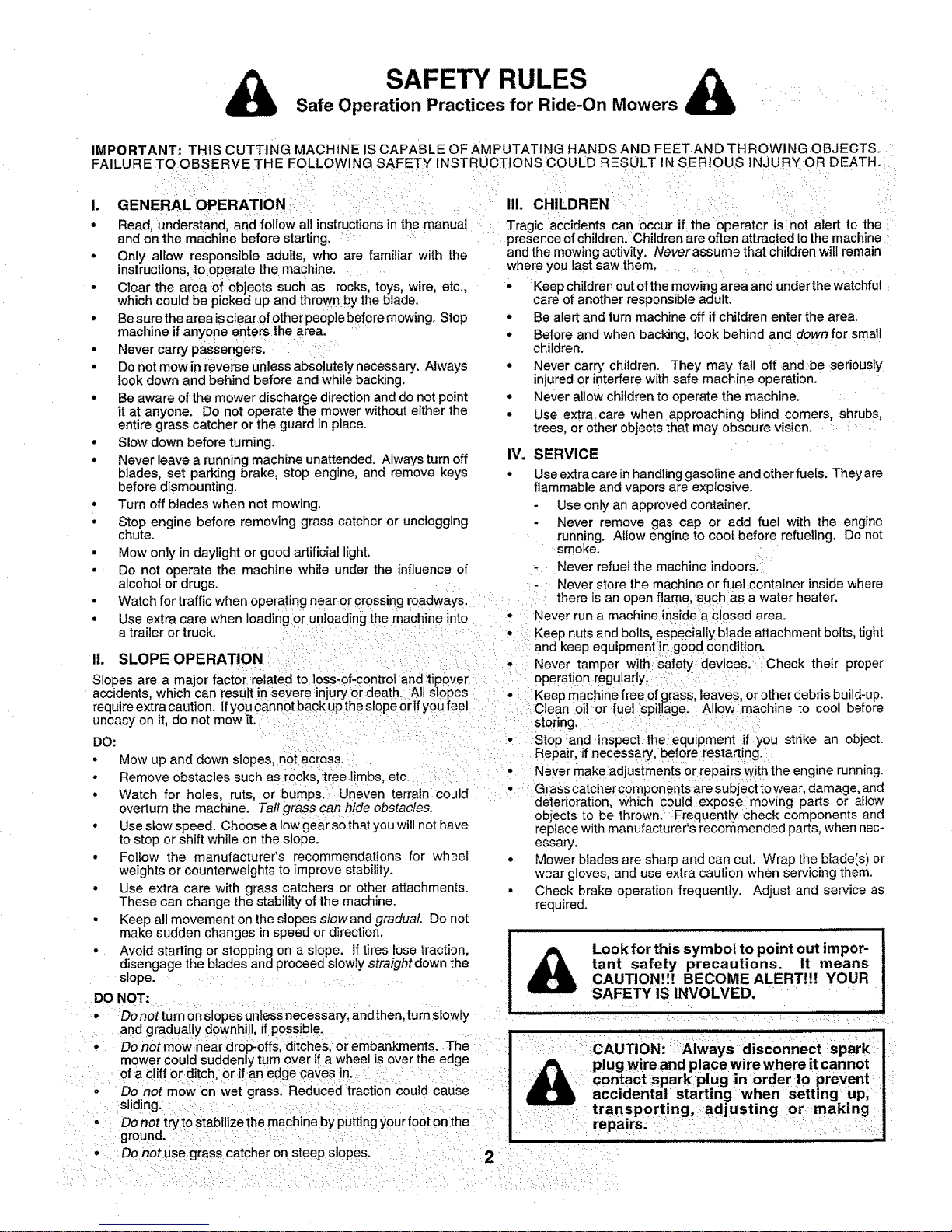
SAFETY RULES &
Safe Operation Practices for Ride-On Mowers
IMPORTANT: THIS CUTTING MACHINE IS CAPABLE OF AMPUTATING HANDS AND FEET AND THROWING OBJECTS.
• Only allow responsible adults, who are familiar with the
instructions to operate the machine.
- Clear the area of objects such as rocks, toys, wire, etc.,
which could be picked up and thrownby the blade,
• Besure the area isclearofother people before mowing. Stop
machine if anyone enters the area.
° Never carry passengers. _ : ::::
• Do not mow in reverse unless absolutely necessary, Always
look down and behind before and while backing.
• Be aware of the mower discharge direction and do not point
it at anyone. Do not operate the mower without either the
entire grass catcher or the guard in place.
• Slow down before turning.
• Never leave a running machine unattended. Always turn off
blades, set parking brake, stop engine, and remove keys
before dismounting.
• Turn off blades when not mowing.
° Stop engine before removing grass catcher or unclogging
chute.
° Mow only in daylight or good artificial light,
• Do not operate the machine while under the influence of
alcohol or drugs ...... : ,
and the mowing activity. Never assume that children will remain
where you last saw them .... .....
• Keep children out of the mowing area and under the watchful
care of another responsible adult.
• Be alert and turn machine off if children enter the area.
° Before and when backing, look behind and down for small
children,
• Never carry children. They may fall off andbe seriously
injured or interfere with safe machine operation.
° Never allow children to operate the machine,
• Use extra care when approaching blind corners, shrubs,
trees, or other objects that may obscure vision.
IV. SERVICE : :
• Use extra care in handling gasoline and other fuels, They are
flammable and vapors are explosive,
- Use only an approved container,
- Never remove gas cap or add fuel with the engine
running. Allow engine to cool before refueling, Do not
smoke. : ....
, Never refuel the machine indoors.:
-Never store the machine or fuel :container inside where
° Watch for traffic when operating near or crossing roadways. : there is an open flame, :such as a water heater.
° Use extra care when loading or unloading the machine into " :Never run a machine ins!de a _!osed area.
a trailer or truck. _i:i: :_:::= :: : : : , : Keep nuts and bolts especially blade attachment bolts tight
...... :: :i and keep equipm_nt]rt g00d €ondition.
II. SLOPE OPERATION : :::: : : ::::i(:i:: ::ii:: : i_i i: _Never tamper with :'safety deviceS.: 'Check their proper
Slopes are a major factor reiated to loss-of-control andtipover := _i=:i _ Operationregularlyl :i: =::i:
accidents, which can All st0pes : Keeomachine free0f arass leaves or other debris build-up.
require extra caution, ifyou cannot back up the slope erif you feel ::: :c ea.n:0 or rue spi _ge: A low 'roach ne to cool befo;'e
uneasy on it, do not mow it. I .:: : :: JiLl:i :storingii:::i :i: ::;:::::: : : :
DO: i: ::= :; ::_ : i: :, i::iStop :and inspect the:equipment :if you strike an object.
• Mow up and down slopes n0i across.::: : :: Repair!
• : : : : : : • Never make adjustments or repairs with the engine running
Remove obstacles such as rocks tree hmbs etc. :: : _ : ......
......... ,_ :.... , :,:_ :L..,_, , ::Grasscatchercomponentsaresubjecttowear, damage, and
• watcn for hOleS ruts or Dumps., uneven terral{i coulu : : _. .. :_. ,_ ....
° Use slow speed. Ch0ose a Iow gear so that you will not have
to stop or shift while on the slope.
° Follow the manufacturer's recommendations for wheel
weights or counterweights to improve stability.
° Use extra care with grass catchers or other attachments.
These can change the stability of the machine.
• Keep all movement on the slopes slowand gradual. Do not
make sudden changes in speed or direction.
° Avoid starting or stopping on a slope. If tires lose traction,
disengage the blades and proceed slowly straight down the
slope.... i :i
DO NOT: .................
: O =::Donotturnonslopesunlessnecessary, andthen, turnlslowly
and gradually downhill, if possible ................
: : Do not mow near dr0p:-0ff& ditches, or embankments. The : :ii::
•mower could suddenly turn over if a wheel is over the edge
: Ofa c!iff or ditc h,:or if an edge cayes in: _:: : : _: :ii :: :
..... ' Do nOtmow onwet :grassl Reduced tracti0n could Cause
o
replace with manufacturer's recommended parts, when nec-
essary.
Mower blades are sharp and can cut. Wrap the blade(s) or
wear gloves, and use extra caution when servicing them.
Check brake operation frequently. Adjust and service as
required.
Look for this symbol to point out impor-
tant safety precautions. It means
CAUTION!!! BECOME ALERT!!! YOUR
SAFETY IS INVOLVED. ......
_.:iii::Ii:: i := CAUTIONi ::Always idisconnect Spark: ;" i
plug wire and place wire where it cannot
i contact spark plug in order to ;prevent
accidental starting when Setting :up,
;:::sliding" ::i :ii::i:: :::::::::_:: ;: : :_ : : i: _ :::: : transporting, adjusting or: making
: .... Donottrytostabi zethemachinebyputtingyourfootonthel : :: repairs: : : .: : :' :; :: ::
: : :; :D0 not use:graSs catcheron steep SlopeS: .... ::::2 : ;:::i : :::::::i :: :::::

CONGRATULATIONS on your purchase of a Sears
Tractor. It has been designed, engineered and manufac-
tured to give you the best possible dependability and
performance.
Should you experience any problem you cannot easily
remedy, please contact your nearest Sears Authorized
Service Center!Department. We have competent, well-
trained technicians and the proper tools to service or repa r
this tractor. , : ....
Please read and retain this manual, The instructions writ
enable you to assemble and maintain your unit properly.
Always observe the "SAFETY RULES".
MODEL
NUMBER 917.252530
SERIAL
NUMBER
DATEOFPURCHASE
THE MODEL AND SERIAL NUMBERS WILL BE FOUN D
ON A PLATE UNDER THESEAT.
YOU SHOULD REcoRD BOTH SERIAL NUMBER AND
DATE OF PURCHASE AND KEEP IN A SAFE PLACE
FOR FUTURE REFERENCE,
MAINTENANCE AGREEMENT
A Sears Maintenance Agreement is available on this prod-
uct, Contact your nearest Sears store for details.
CUSTOMER RESPONSIBILITIES
• Read and observe the safety ru]es.
• Follow a regular schedule in maintaining, caring for and
using your tractor.
• Follow the instructions under "Customer Responsibili-
ties" and "Storage" sections of this owner's manual.
PRODUCT SPECIFICATIONS
HORSEPOWER: 15.0
GASOLINE CAPACITY 5 QUARTS
AND TYPE: UNLEADED REGULAR
OIL TYPE (API-SF/SG): SAE 30 (above 32°F) _:
SAE 5W-30 (below 32°F)
OiL CAPACITY: 3.0 PINTS
SPARK PLUG: CHAMPION RJ-19LM
(GAP: .030") STD361458
VALVE CLEARANCE: INTAKE: .005" - .007" '
EXHAUST: .009" - .011"
GROUND SPEED (MPH): FORWARD: 5.5
REVERSE: 2.5
TiRE PRESSURE: FRONT: 14 PS!
REAR: 10 PSi
CHARGING SYSTEM: 3 AMPS BATTERY
5 AMPS HEADLIGHTS
BLADE BOLT TORQUE: 30-35 FT. LBS.
WARNING: This tractor is equipped with an internal
combustion engine and should not be used on or near any
unimproved forest-covered, brush-covered or grass-cov-
ered land unless the engine's exhaust system isequipped
with a spark arrester meeting applicable local or state laws
(if any). If a spark arrester isused, it should be maintained
in effective working order by the operator.
In the state of California the above is required by law
(Section 4442 of the California Public Rosources Code).
Other states may have similar laws. Federal iaws apply on
federal lands. A spark arrester for the muffler is available
through your nearest Sears Authorized Service Center/
Department (See REPAIR PARTS section of this manual).
LIMITED TWO YEAR WARRANTY ON ELECTRIC START RIDING EQUIPMENT
For two (2) years from the date of purchase, if this riding equipment is maintained, lubricated and tuned up according to the
instructions in the owner's manual, Sears wiil repair or repiace, free of charge, any parts found to be defective in material or
workmanship.
This Warranty does not cover:
• Expendable items which become worn during normal use, such as blades, spark plugs, air cleaners and belts.
• Tire replacement or repair caused by punctures from outside objects, suc h as nails, thorns, stumps, or glass.
• Repairs necessary because of operator abuse, negligence, improper storage or accident or the failure to maintain the
equipment according to the instructions contained in the owner's manual.
• Riding equipment used for commercial or rental purposes.
LIMITED 90 DAY WARRANTY ON BATTERY ....
For ninety (90) days from date of purchase, if any battery included with this riding equipment proves defective in material or
.workmanship and our testing determines the battery will not hold a charge, Sears will replace the battery at no charge.
WARRANTY SERVICE IS AVAILABLE BY RETURNING THE RIDING EQUIPMENT TO THE NEAREST SEARS SERVICE
CENTER/DEPARTMENT iN THE UNITED STATES.
This Warranty gives you specific tega!rights, and you may also have other rights which may vary from state to state.
SEARS, ROEBUCK AND CO., D/817 WA, HOFFMAN ESTATES, ILLINOIS 60179
. ,rl i rllllmrll H r H
3
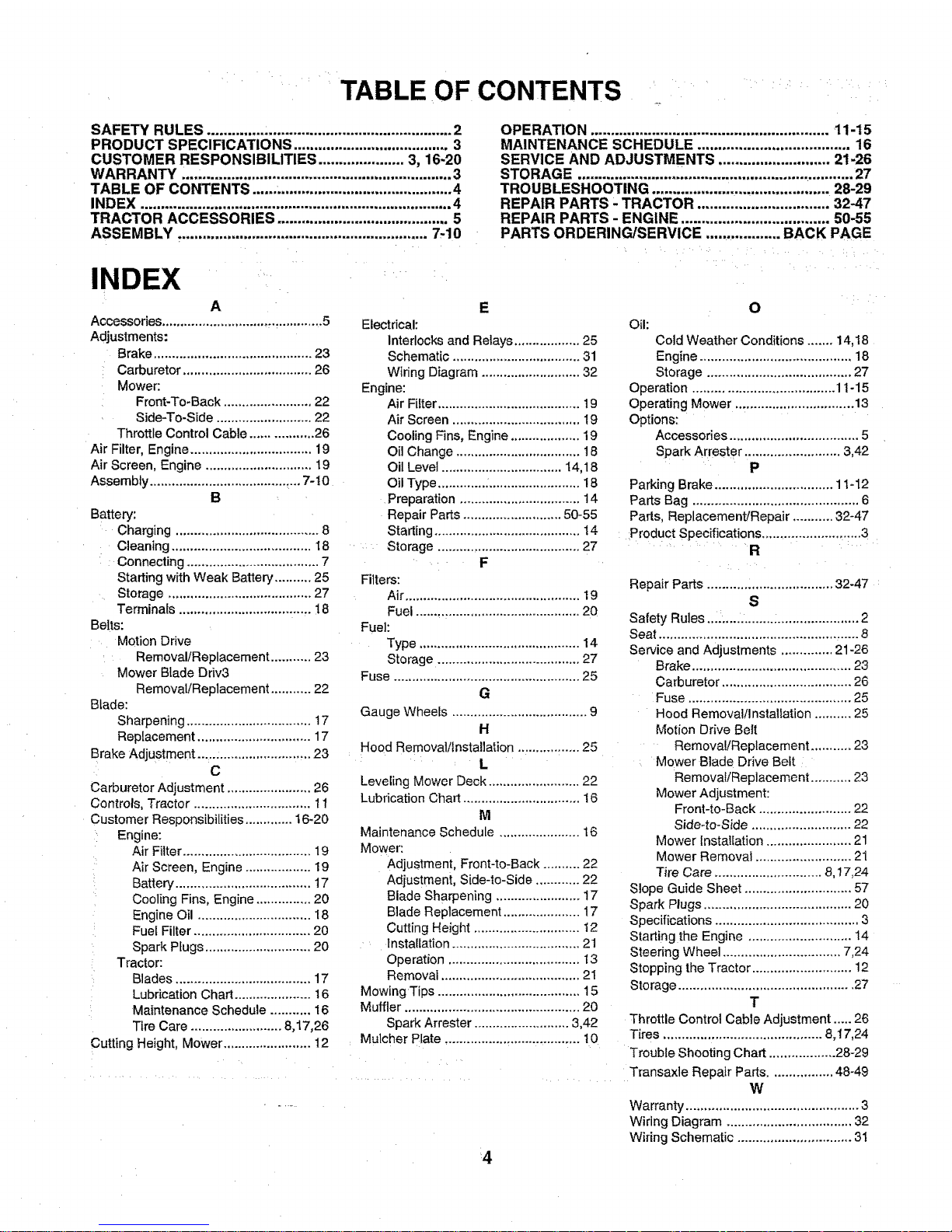
TABLE OF CONTENTS
SAFETY RULES ............................................................ 2
PRODUCT SPECIFICATIONS ...................................... 3
CUSTOMER RESPONSIBILITIES ..................... 3, 16-20
WARRANTY .... ,............................................................. 3
TABLE OF CONTENTS ...... ........................................... 4
INDEX ............................................................................ 4
TRACTOR ACCESSORIES .......................................... 5
ASSEMBLY ............................................................. 7,10
INDEX
A
Accessories............................... _............5
Adjustments:
Brake ........................................... 23
Carburetor ................................... 26
Mower:
Front-To-Back ........................ 22
Side-To-Side .......................... 22
Throttle Control Cable ................. 26
Air Filter, Engine ................................. 19
Air Screen, Engine ............................. 19
Assembly ..................................... _...7-t0
B
Battery:
Charging ....................................... 8
Cleaning ...................................... 18
Connecting .................................... 7
Starting with Weak Battery .......... 25
Storage ....................................... 27
Terminals .................................... t 8
Belts:
Motion Drive
Removal/Replacement ........... 23
Mower Blade Driv3
Removal!Replacement ........... 22
Blade:
Sharpening .................................. 17
Replacement ............................... 17
Brake Adjustment ............................... 23
C
Carburetor Adjustment ....................... 26
Controls, Tractor ................................ 11
Customer Responsibilities ............. 16-20
Engine:
Air Filter ................................... 19
: Air Screen, Engine .................. 19
Battery ..................................... 17
Cooling Fins, Engine ............... 20
Engine Oil ............................... 18
Fuel Filter ................................ 20
Spark Plugs ............................. 20
Tractor:
Blades ..................................... 17
Lubrication Chart ..................... 16
: Maintenance Schedule ........... 16
Tire Care ......................... 8,17,26
Cutting Height, Mower ........................ 12
OPERATION .......................................................... 11-15
MAINTENANCE SCi-IEDMLE ..................................... 16
SERVICE AND ADJUSTMENTS ........................... _)1_6
STORAGE .................................................................... 27
TROUBLESHOOTING ........................................... 28-_)9
REPA|R PARTS _ TRACTOR ................................ 3_"_47
REPAIR PARTS - ENGINE .................................... 50155
PARTS ORDERING/SERVICE .................. BACK PAGE
E
Electrical:
interlocks and Relays .................. 25
Schematic ................................... 31
Wiring Diagram ........................... 32
Engine:
Air Filter ....................................... 19
Air Screen ................................... 19
Cooling Fins, Engine ................... 19
Oil Change .................................. 18
Oil Level ................................. 14,18
Oil Type ............. :......................... 18
Preparation ................................. 14
Repair Parts ........................... 50-55
Starting ........................................ t4
: Storage ....................................... 27
F
Filters:
Air ................................................ 19
Fuel ............................................. 20
Fuel:
Type ............................................ 14
Storage ....................................... 27
Fuse ................................................... 25
G
Gauge Wheels ..................................... 9
H
Hood Removal/installation ................. 25
L
Leveling Mower Deck ......................... 22
Lubrication Chart ................................ !6
M
Maintenance Schedule ...................... 16
Mower:
Adjustment, Front-to:Back .......... 22
Adjustment, Side-to-Side ............ 22
Blade Sharpening ....................... 17
Blade Replacement ..................... 17
Cutting Height ............................. t2
, Installation ................................... 21
Operation .................................... I3
Removal ...................................... 21
Mowing Tips ....................................... 15
Muffler ................................................ 20
Spark Arrester .......................... 3,42
Mulcher Plate ..................................... 10
'4
O
Oil:
Cold Weather Conditions ....... 14,18
Engine ......................................... 18
Storage ....................................... 27
Operation ...................................... 11-15
Operating Mower ................................ 13
Options:
Accessories ................................... 5
Spark Arrester ..................... 3,42
P
Parking Brake ................................ 11-12
Parts Bag ............................................. 6
Pads, Replacement/Repair ........... 32-47
:ProductSpecifications ........................... 3
a
Repair Parts .................................. 32-47
S
Safety Rules....;.... .........:...................... 2
Seat ................................................ ,..... 8
Service and Adjustments .............. 21-26
Brake ........................................... 23
Carburetor ................................... 26
Fuse ............................................ 25
Hood Removal/Insta!lation .......... 25
Motion Drive Belt
Remova!/Replacement ........... 23
Mower Blade Drive Belt
Removal/Replacement ........... 23
Mower Adjustment:
Front-to-Back ......................... 22
Side-to-Side ........................... 22
Mower Installation ....................... 21
Mower Removal .......................... 21
Tire Care ............................. 8,17,24
Slope Guide Sheet ............................. 57
Spark Plugs ........................................ 20
Specifications ....................................... 3
Starting the Engine ............................ 14
Steering Wheel ................................ 7,24
Stopping the Tractor ........................... 12
Storage ............................................... 27
T
Throttle Control Cable Adjustment ..... 26
Tires ........................................... 8,17,24
Trouble Shooting Chart .................. 28-29
Transaxte Repair Parts................. 48-49
W
Warranty ............................................... 3
Wiring Diagram .................................. 32
Wiring Schematic ............................... 31
i i iiiiiiiiiiiiil,,,, ill illllllll lit HI,I,,,,,, II i,,
IIIIIIIIIIIII /11/_1 ill ii
AND ATTACHMENTS
iiiii IIIIIIIIII i III/ I
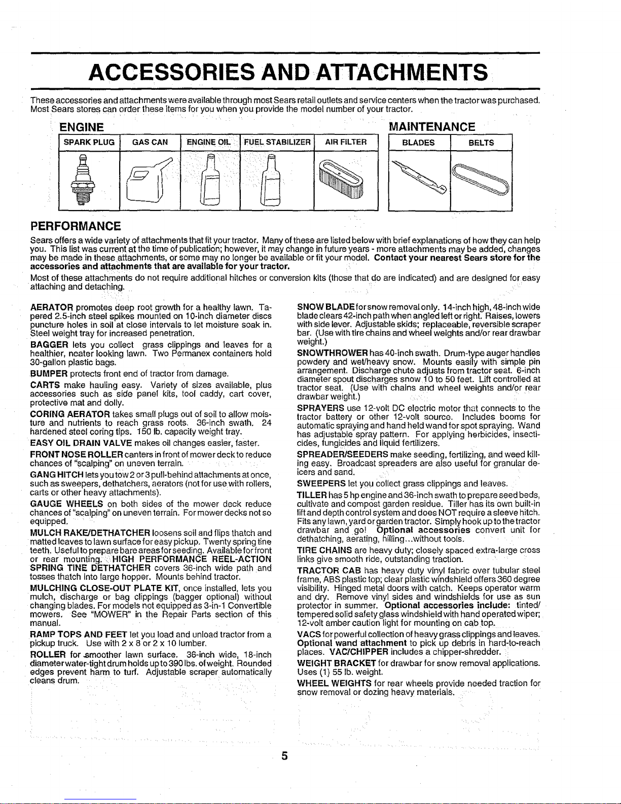
These accessories and attachments were available through most Sears retail outlets and service centers when the tractor was purchased,
Most Sears stores can order these items for you when you provide the model number of your tractor.
ENGINE
SPA"KPLUG.............GASCAN
j?
I ENG!NE olL_::
AIR FILTER
%
MAINTENANCE
BLADES BELTS
PERFORMANCE
Sears offers awide vadety ofattachments that fit your tractor. Many of these are listed below with bdef explanations of how they canhelp
you. This listwas current at the time of publication; however, itmay change in future years - more attachments may be added, changes
may be made in these attachments, or some may no longer be available or tit your model, Contact your nearest Sears store for the
accessories and attachments that are available for your tractor, i
Most of these attachments do not requireadditional hitches or conversion kits (those that do are indicated) and are designed for easy
attaching anddetaching. .....
AERATOR promotes deep root growth for a healthy lawn. Ta-
pered 2.5-inch steel spikes mounted on 10-inch diameter discs
puncture holes in soil at close intervalsto let moisture soak in.
Steel weight tray for increased penetration,
BAGGER lets you collect grass clippings and leaves for a
healthier, nearer looking lawn. Two Permanex containers hold
30-gallon plastic bags.
BUMPER protectsfront end of tractor from damage.
CARTS make haufing easy. Variety of sizes available, plus
accessories such as side panel kits, tool caddy, cart cover,
protective mat and dolly.
CORING AERATOR takes sma{Iplugs out of soil to a{Iow mo{s-
lure and nutrients to reach grass roots. 36-inch swath. 24
hardened steel coring tips. 150 lb. capacity weight tray.
EASY OIL DRAIN VALVE makes oil changes easier, faster.
FRONT NOSE ROLLER canters infront ofmower deekto reduce
chances of "scalping" on uneven terrain.
GANG HITCH letsyou tow 2 or3 pull-behind attachments atonce,
such as sweepers, dethatchers, aerators (not for use with rollers,
carts or other heavy attachments).
GAUGE WHEELS on both sides of the mower deck reduce
chances of "scalping" on uneven terrain. For mower decks not so
equipped.
MULCH RAKE/DETHATGHER loosens soil and flips thatch and
matted leaves to lawn surface for easy pickup. Twenty spring tine
teeth. Useful toprepare bare areas forseeding. Available for front
or rear mounting. : HIGH PERFORMANCE REEL-ACTION
SPRING TINE DETHATCHER covers 36-inch wide path and
tosses thatch into large hopper. Mounts behind tractor.
MULCHING CLOSE-OUT PLATE KIT, once installed, lets you
mulch, discharge or bag clippings (bagger optional) without
changing blades. For models not equipped as 3-[n-1 Convertible
mowers. See "MOWER" in the Repair Parts section of this
manual.
RAMP TOPS AND FEET let you loadand un[oad tractor trom a
pickuptruck. Use with 2 x 8 or 2 x 10 lumber.
ROLLER for .smoother lawn surface. 36-inch wide, 18-inch
diameter water-tight drum holds up to 390 Ibs.ofweight. Rounded
edges prevent harm to turf. Adjustable scraper automatically
cleans drum.
SNOW BLADEforsnow remova[only. 14-inchhigh, 48-inch wide
blade clears 42-inch path when angtedleff or right. Raises,lowers
with side lever. Adjustable skids; replaceable, reversible scraper
bar. (Usewith tire chains and wheel weights and/or rear drawbar
weight.)
SNOWTHROWER has 40-inch swath. Drum-type auger handles
powdery and wet/heavy snow. Mounts easily with simple pin
arrangement. Discharge chute adjusts from tractor seat. 6-inch
diameter spout discharges snow !0 to 50 feet. Lift controlled at
tractor seat. (Use with chains and wheel weights and!or rear
drawbar weight.)
SPRAYERS use 12-volt DC electric motor that connects to the
tractor battery or other 12-volt source. Includes booms for
automatic spraying and hand held wand for spot spraying. Wand
has adjustable spray pattern. For applying herbicides, insecti-
cides fungicides and liquidfertilizers.
SPREADER/SEEDERS make seeding, fertilizing, and weed kill-
ing easy. Broadcast spreaders are also useful for granular de-
icers and sand.
SWEEPERS let you Collect grass clippings and leaves.
TILLER has 5 hp engine and 36-inch swath to prepare seed beds,
cultivate and compost garden residue. Tiller has itsown built-in
liftand depth control system and does NOT require a sleeve hitch.
Fits any lawn, yard or garden tractor. Simply hook up to the tractor
drawbar and go! Optional accessories convert unit for
dethatching, aeratirlg, hilling...without toots.
TIRE CHAINS are heavy duty; closely spaced extra-large cross
links give smooth ride, outstanding traction.
TRACTOR CAB has heavy duty vinyl fabric over tubular steel
frame, ABS plastic top; clear plastic windshield offers 360 degree
visibility. Hinged metal doors with catch. Keeps operator warm
and dry. Remove vinyl sides and windshields for use as sun
protector in summer. Optional accessories include: tinted/
tempered solid safety glass windshield with hand operated wiper;
12.volt amber caution light for mounting on cab top.
VACS for powerful collect{on of heavy grass clippings and leaves.
Optional wand attachment to pick up debris in hard-to-reach
places. VACICHIPPER includes a chipper-shredder.
WEIGHT BRACKET for drawbar for snow removal applications.
Uses (1) 55 lb. weight.
WHEEL WEIGHTS for rear wheels provide needed traction for
snow removal or dozing heavy materials.
5

..... lain Ill i ]ln l ill, II I==
CONTENTS OF HARDWARE PACK
i i,alll,,,i,, iii ,,,,,,,,,,,,,,,, ,,,,, t t i ,,, ,,,,,,,, ,,, , ,,,,,,,,, ,, i t
............ ,i,ii
Parts packed separately in carton
i t iii/_iitilitiiiiiit it tttttllltl it it I
Parts Bag contents shown full size
i i it
i i ii
O
(1) Large Flat Washer
t (2) Sheet
Metal
Screws
#10-16 x 1/2
i!!ll]lltll1t,"
(1) Shoulder Bolt 5/16-18 (1) Hex Bolt t/2-13 x 1
(1) LockWasher 1/2 _
(1) Washer 17/32 x 1-3/16 x 12 Gauge
(2) Screws #10 x 5/8 (2) Lock Washers #10
_Waihers :ug_ i:
(2) Weld Nuts #10
3/16 x 3/4 x 16 Ga
! "litt't/lil't'l"i' @
t2) Hex Bolts 1/4-20 x 3/4
(2) Hex Nuts 1/4-20
[2) Washers 9/32 x 5/8 x 16 Gauge _
(2) Lock Washers 1/4
Seat
Steering
Wheel
Battery acid
Steering
Boot
Owner's Manual
Mulcher
Plate
Parts Bag
i i i, i i
Parts bag contents not shown full size
i
(2) Washers 3/8
Shoulder _/ !q_ x 7/8 x 14 Gauge
(2)
Bolts i )._/Z_ l _'_ (2) Center-
_," ^, _/ lock Nuts
(z) Gauge
Wheels <_
Steering Wheel
Adapter@@
Steering
(2) Latch Hook Wheel Steering
Assemblys Insert Bushing
(2) Keys
Slope Sheet
,i i r i
Battery Caps
and Instructions
H,
6
ASSEMBLY
,,,,,,,,,,,,,=, ii wii i i llnln i I II ,,, ii III I
Your new tractor has been assembled at the factory with exception of those parts left unassembled for shipping purposes.
To ensure safe and proper operation of your tractor all parts and hardware you assemble must be tightened securely. Use
the correct tools as necessary to insure proper tightness.
TOOLS REQUIRED FOR ASSEMBLY
A socket wrenchset will make assembly easier. Standard
wrench sizes are listed,
(1) 5/16" wrench (1) 3/4" Socket w!drive rachet
(2) 7/t6" wrenches Phillips Screwdriver
(1) !/2" wrench Tire pressure gauge
(1) 9/16" wrench Utility knife
When right or left hand is mentioned in this manual, it
means when you are in the operating position (seated
behind the steering wheel).
TO REMOVE TRACTOR FROM CARTON
UNPACK CARTON
- Remove all accessible loose parts and parts cartons
from carton (See page 6).
° Cut, from top to bottom, along lines on all four corners
of carton, and lay panels flat.
° Check for any additional loose parts or cartons and
remove.
o
BEFORE ROLLING TRACTOR OFF SKID
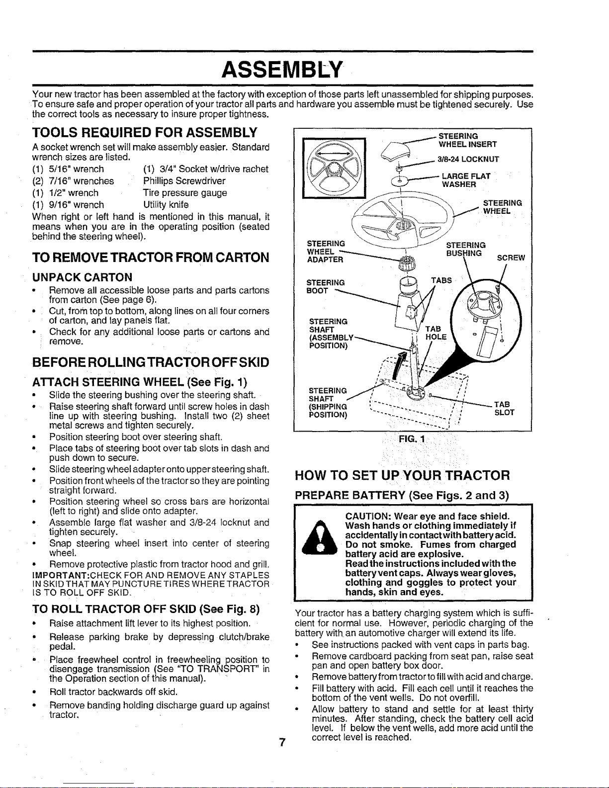
ATTACH STEERING WHEEL (See Fig. 1)
• Slide the steering bushing over the steering shaft.
° Raise steering shaft forward until screw holes in dash
iine up with steering bushing. Install two (2) sheet
metal screws and tighten securely.
• Position steering boot over steering shaft.
• Place tabs of steering boot over tab slots in dash and
push down to secure.
• Slide steering wheel adapter onto upper steering shaft.
• Position front wheels of the tractor sothey are pointing
straight forward.
° Position steering wheel so cross bars are horizontal
(left to right) and slide onto adapter.
Assemble large fiat washer and 3/8-24 locknut and
tighten securely.
Snap steering wheel insert into center of steering
wheel.
• Remove protective plastic from tractor hood and grill.
IMPORTANT:CHECK FORAND REMOVE ANY STAPLES
1NSKID THAT MAY PUNCTURE TIRESWHERE TRACTOR
IS TO ROLL OFF SKID.
TO ROLL TRACTOR OFF SKID (See Fig. 8)
• Raise attachment lift lever to its highest position.
• Release parking brake by depressing clutch/brake
pedal.
• Place freewheel control in freewheeling position to
disengage transmission (See 'q'O TRANSPORT" in
the Operation section of this manual). '
• Roll tractor backwards off skid.
° Remove banding holding discharge guard up against
tractor.
WHEEL
ADAPTER
STEERING
BOOT
STEERING
SHAFT
I BUSHING
SCREW
ABS
_/ TAB
POSITION)
STEERING , ,',
SHAFT :'-" TAB
(SHIPPING
POSITION) ' , SLOT
FIG. 1
7
HOW TO SET UP YOUR TRACTOR
PREPARE BATTERY (See Figs. 2 and 3)
CAUTION: Wear eye and face shield.
Wash hands or clothing immediately if
accidentally incontact with battery acid.
Do not smoke. Fumes from charged
battery acid are explosive.
Read the instructions included with the
batteryvent caps. Always wear gloves,
clothing and goggles to Protect your
hands, skin and eyes.
nllllnl
Your tractor has a battery charging system which is suffi-
cient for normal use. However, periodic charging of the
battery with an automotive charger will extend its life.
• See instructions packed with vent caps in parts bag.
• Remove cardboard packing from seat pan, raise seat
pan and open battery box door.
• Remove battery from tractor to fill with acid and charge.
• Fill battery with acid. Fill each ceil until it reaches the
bottom of the vent wells. Do not overfill.
° Allow battery to stand and settle for at least thirty
minutes. After standing, check the battery cell acid
level. If below the vent wells, add more acid until the
correct level is reached.
....... H
While battery isstanding (after adding acid) and faterl while
battery is being charged, continue with assembly oftractor.
IMPORTANT: TO MAXIMIZE THE LIFE OF YOUR
BATTERY, IT fS NECESSARY THAT THE BATTERY BE
CHARGED BEFORE USE. FAILURE TO CHARGE
BATTERY CAN RESULT iN A SHORTENED BATTERY
LIFE.
Charge battery at a rate of 6 amperes for I hour. Use
a 12 volt battery charger. Observe all safety precau-
t{ons required for battery charging.
Checkthe acid level after the battery is charged. If the
acid has fallen below the correct level, add distilled or
iron free water.
Install the vent caps to cover the vent wells. Wash the
top of the battery with water to remove any acid, then
:wipe dry.
Check battery case for leakage to make sure that no
damage has occurred in handling.
Dispose of excess battery acid. Neutralize acid for
disposal by adding it to two gallons of water in a five
gallon plastic container. Stir with a wooden or plastic
paddle while adding baking soda until the addition of
more soda causes no more foaming,
Follow instructions on how to install battery.
SEAT PAN
i, VENT WELL
LEVEL
BATFERY
o
FIG. 2
CUT AWAY VIEW
FIG. 3
Ly_ •
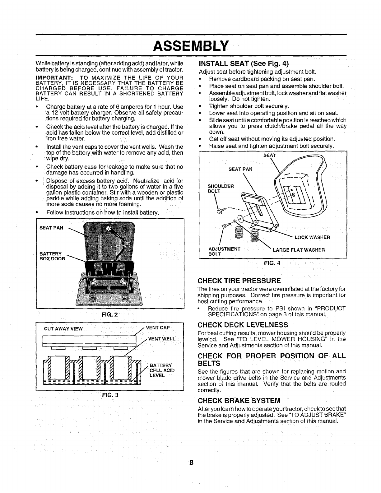
INSTALL SEAT (See Fig. 4)
Adjust seat before tightening adjustment bolt.
• Remove cardboard packing on seat pan.
• Place seat on seat pan and assemble shoulder bolt.
• Assemble adjustment bolt, lock washerand flat washer
loosely. Do not tighten.
• Tighten shoulder bolt securely.
o Lower seat intooperating position and sit on seat.
• Slideseat until a comfortable position is reached wh{ch
allows you to press clutch/brake pedal all the way
down.
• Get off seat without moving its adjusted position.
• Raise seat and tighten adjustment bolt securely.
BOLT
FIG. 4
CHECK TIRE PRESSURE
The tires on your tractor were overinflated at the factory for
shipping purposes. Correct tire pressure is important for
best cutting performance.
• Reduce tire pressure to PSi shown in "PRODUCT
SPECIFICATIONS" on page 3 of this manual.
CHECK DECK LEVELNESS
Forbest cutting results, mower housing should be properfy
leve]ed. See '%0 LEVEL MOWER HOUSING" in the
Service and Adjustments section of this manual.
CHECK FOR PROPER POSITION OF ALL
BELTS
See the figures that are shown for replacing motion and
mower blade drive belts in the Service and Adjustments
section Ofthis manual. Verify that the belts are routed
correctly.
CHECK BRAKE SYSTEM
After you learn how to operate you rtractor, check to see that
the brake iSproperly adjusted. See '%0 ADJUST BRAKE"
in the Service and Adjustments section of this manual.
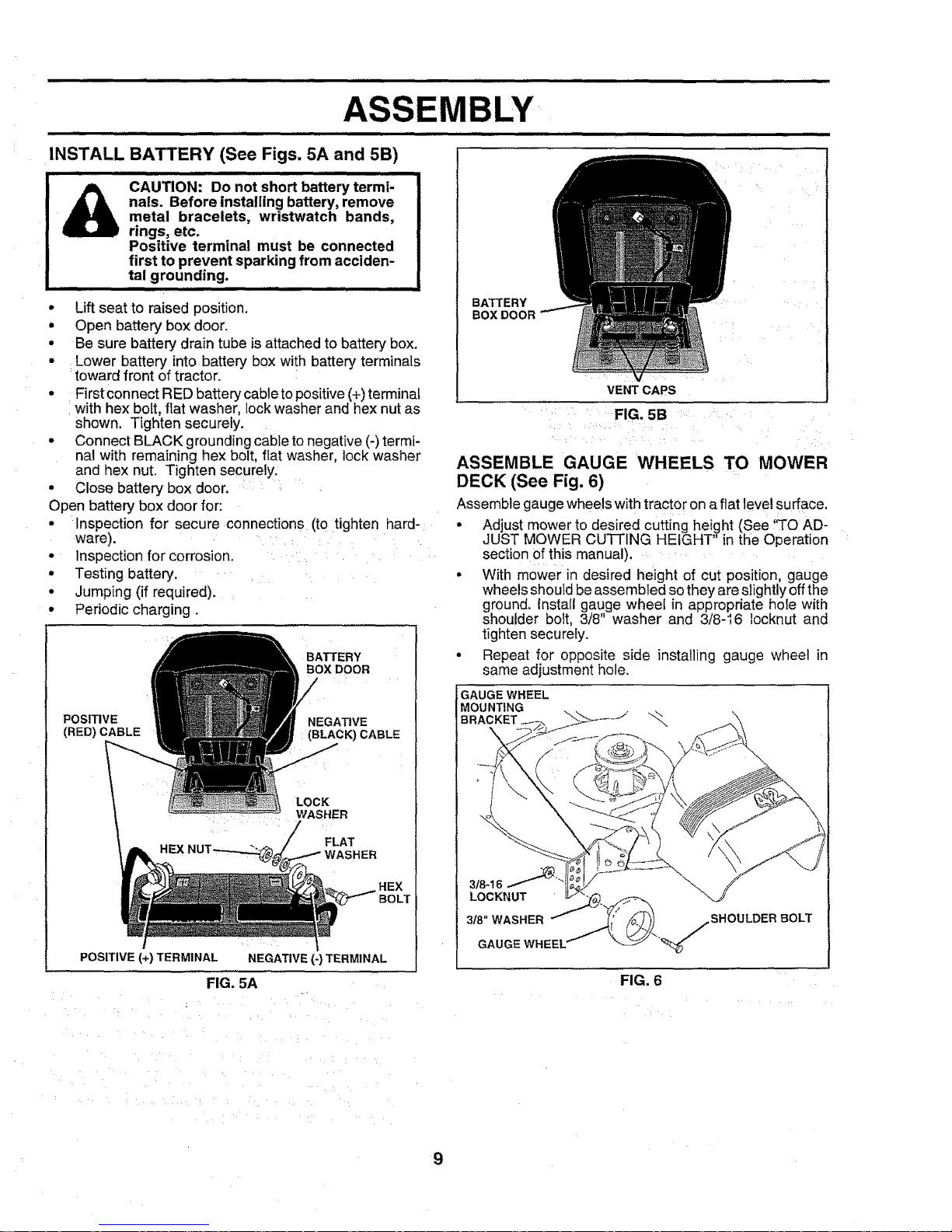
INSTALL BATTERY (See Figs. 5A and 5B)
i i i i ii i,,i,l,,,,,,m
CAUTION: Do not short battery termi-
nals. Before installing battery, remove
metal bracelets, wristwatch bands,
rings, etc.
Positive terminal must be connected
first to prevent sparking from acciden-
tal grounding.
• Liftseat to raised position.
• Open battery box door.
• Be sure battery drain tube is attached to battery box.
• Lower battery into battery box with battery terminals
_toward front of tractor.
= First connect RED battery cable topositive(+) terminal
with hex bolt, fiat washer, lock washer and hex nut as
shown. Tighten securely.
• Connect BLACK grounding cableto negative (-)termi-
nal with remaining hex bolt, flat washer, lock washer
and hex nut. Tighten securely,
° Close battery box door. _ ,
Open battery box door for:
• Inspection for secure connections (to tighten hard-
ware) ....
inspection for corrosion.
BATTERY
BOX DOOR
• Testing battery.
• Jumping (if required).
° Periodic charging.
NEGATIVE
(BLACK) CABLE
LOCK
: : .... _HER
POSITIVE
(RED) CABLE
POSITIVE (+) TERMINAL NEGATIVE (-) TERMINAL
FIG. 5A
;
BLY¸
BATTERY
BOX DOOR
VENT CAPS
HH,,II
FIG. 5B
: i
ASSEMBLE GAUGE WHEELS TO MOWER
DECK (See Fig. 6)
Assemble gauge wheels with tractor on a flat evel surface.
• Adjust mower to desired cutting height (See 'q'O AD-
JUST MOWER Cu]-rlNG HEIGHT in the Operation
section of this manual). .....
° With mower in desired height of cut position, gauge
wheels should be assembled so they are slightly off the
ground. Install gauge wheel in appropriate hole with
shoulder bolt, 3/8 washer and 3/8-16 locknut and
tighten securely.
Repeat for opposite side installing gauge wheel in
same adjustment hole.
I GAUGE WHEEL
bUNTING
LOCKNUT
3_"WASHER
GAUGE WHEE_
\
.,_fSHOULDER BOLT
FIG. 6
9
_...................... iiil,lll ill ii_ll,ll,i n ii i I, H iiil,lll,llll i illll i il,,,,i Hill, III,HIIIIII I III/
ASSEMBLY
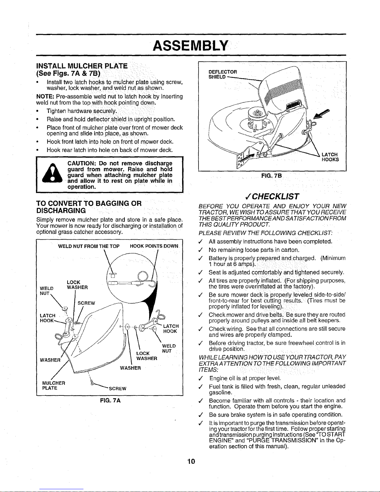
• Install two latch _hooksto mulcher plate :using screw,
washer, lock washer, and weld nut as shown.
NOTE: Pre-assembleweid nut:to ilatch h0okby inserting
weld nut from the top with :hook pointing down.
• Tighten hardwaresecurely._i _::
• Raiseandholddeflecto shieiduPr ghtposition.
• Place front of mulcher p!ateover fr0nt of mower deck
opening and slide into place as shown.
• Hook front latch intohole on front ofmower deck.
•, Hook rear latch into hole on back of mower deck.
........... ................................
_ CAUTION: Do not remove discharge
| • • guard from mower. Raise and hold
| _ guard when attaching mulcher plate
| _ and allow it to rest on plate while in
! operation. ,,, ,, _ :
TO CONVERT TO BAGGING OR .....
DISCHARGING i_ii _ : _ ii
Simply remove mulcher plate and store in a safe place.
Your :mower is now ready for discharging or nsta!lation of
optional grass :catcher accessory.
WELD NUT FROM THE TOP
LOCK
WELD WASHER
LATCH ,
SCREW
HOOK POINTS DOWN
HOOK
WASHER
MULCHER
PLATE
LOCK
WASHER
WASHER
'_SCREW
FIG. 7A
WELD
NUT
DEFLECTOR
SHIELD "I
LATCH
HOOKS
FIG. 7B
•/ CHECKLIST
BEFORE YOU OPERATE AND ENJOY YOUR NEW
TRACTOR, WE WISH TO ASSURE THAT YOU RECEIVE
THE BEST PERFORMANCE AND SATISFACTION FROM
THIS QUALITY PRODUCT.
PLEASE REVIEW THE FOLLOWING CHECKLIST:
,/ All assembly instructions have been completed.
,," No remaining loose parts in carton.
,/ Batteryis properly prepared and Charged. (Minimum
1 hour at 6 amps).
#" Seat is adjusted comfortably and tightened securely.
¢" All tires are properly inflated. :(For shipping purposes,
the tires were overinflated at the facton]).
,/ Be sure mower deck is propedy leveled side-to-side/
front-to-rear for best Cutting results. (Tires must be
properly inflated for leveling).
v" Check mower and drive belts. Be sure they are routed
properly around pu leys and inside all belt keepers.
,[ Check wiring. See that all connections are still secure
and wires are properly clamped.
,7 Before driving tractor, be sure freewheel control is in
drive position. .....
WHILE LEARNING HOW TOUSE YOUR TRACTOR, PAY
EXTRA ATTENTION TO THE FOLLOWING IMPORTANT
ITEMS: i
,/ Engine oil isat proper level.
,/ Fuel tank is filled with fresh, clean, regular unleaded
gasoline.
,/ Become familiar with all controls - their location and
function. Operate them before you start the engine.
,/ Be sure brake system is in safe operating condition.
,/ It is important to purge the transmission before operat-
ing your tractor for the first time. Follow proper starting
and transmission purging instructions (See'q'O START
ENGINE" and "PURGE TRANSMISSION" in the Op-
eration section of this manual).
10
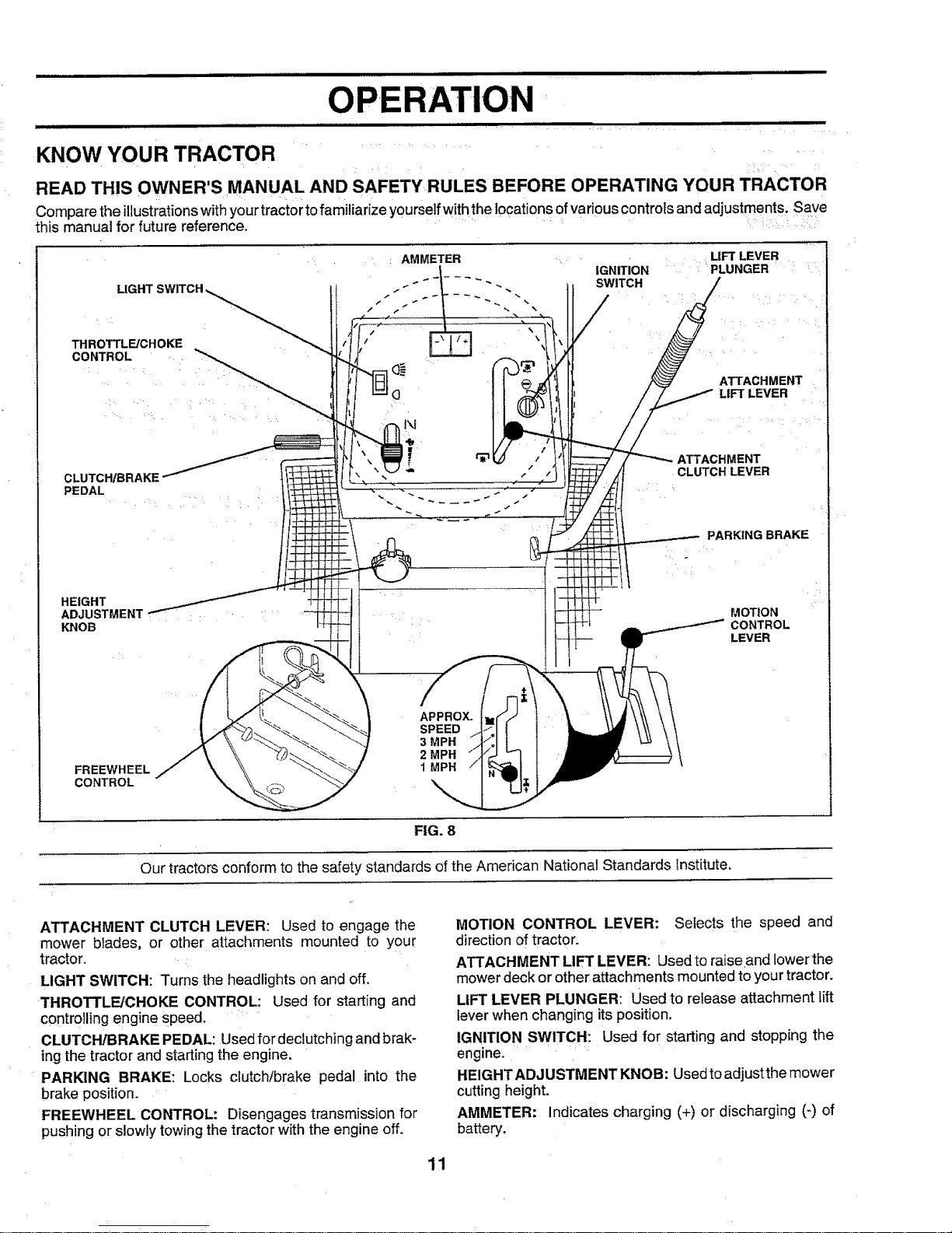
KNOW YOUR TRACTOR
READ THIS OWNER'S MANUAL AND SAFETY RULES BEFORE OPERATING YOUR TRACTOR
Compare the illustrations with your tractor to familiarize yourself withthe locations of various controls and adjustments. Save
this manual for future reference.
THROTTLE/CHOKE
CONTROL
CLUTCHIBRAKE
PEDAL
HEIGHT
ADJUSTMENT
KNOB
: AMMETER LIFT LEVER
IGNITION PLUNGER
SWITCH
ATTACHMENT
LIFT LEVER
_,TTACHMENT
CLUTCH LEVER
PARKING BRAKE
MOTION
CONTROL
LEVER
FREEWHEEL
CONTROL
APPROX.
SPEED
3 MPH
2 MPH
1 MPH
FIG. 8
Our tractors conform to the safety standards of the American National Standards institute.
ATTACHMENT CLUTCH LEVER: Used to engage the
mower blades, or other attachments mounted to your
tractor.
LIGHT SWITCH: Turns the headlights on and off.
THROTTLE/CHOKE CONTROL: Used for starting and
controlling engine sPeed.
CLUTCH/BRAKE PEDAL: Used for deciutching and brak-
ing the tractor and starting the engine.
PARKING BRAKE: Locks clutch/brake pedal into the
brake position.
FREEWHEEL CONTROL: Disengages transmission for
pushing or slowly towing the tractor with the engine off.
MOTION CONTROL LEVER: Selects the speed and
direction of tractor.
ATTACHMENT LIFT LEVER: Used to raiseand lowerthe
mower deck or other attachments mounted to your tractor.
LIFT LEVER PLUNGER: Used to release attachment lift
leverwhen changing its position.
IGNITION SWITCH: Used for starting and stopping the
engine.
HEIGHT ADJUSTMENT KNOB: Usedto adjustthe mower
cutting height.
AMMETER: Indicates charging (+) or discharging (-) of
battery.
11
.............................................................................OPERATION ............................
ttiitttttttt tti tt tt tt imH,,,,,,,,,, ,HI tit ttttttt i ,H,,,,,,,,, ,,,,, iiit t iittitttiii iiiiiiiiiiiiii iii iiit
HOW TO USE YOUR TRACTOR
.... ..................... .......................................................................:L¸¸ ':":"'""'_'i.... ' ":"'":i""i": ....
!
The operation of any tractor can result in foreign objects thrown into the eyes, which can I
result in severe eye damage. Always wear safety glasses or eye shields while operating your |
tractor or performing any adjustments or repairs. We recommend a wide vision safety mask !
over the spectacles or standard safety glasses,.................. .... ,_,_ .......,I
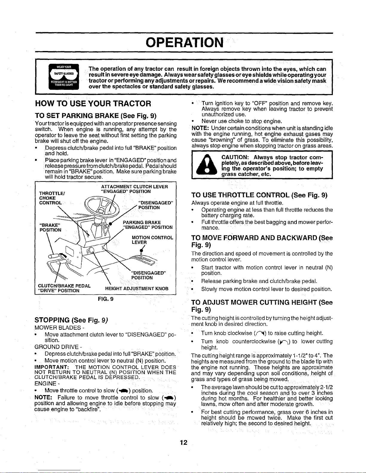
TO SET PARKING BRAKE (See Fig. 9)
Your tractor isequipped with an operator presence sensing
switch. When engine is running, any attempt by the
operator to leave the seat without first setting the parking
brake will shut off the engine.
• Depress clutch/brake pedal intofuil "BRAKE" position
and hold.
• Place parking brake lever in"ENGAGED" position and
release pressure from clutch/brake pedal. Pedal should
remain in "BRAKE" position, Make sure parking brake
will hold tractor secure.
ATFACHMENT CLUTCH LEVER
THROTTLE/ "'ENGAGED" POSITION
CHOKE
CONTROL "DISENGAGED"
*POSITION
PARKING BRAKE
"BRAKE"
POSITION
MOTION CONTROL
,: LEVER
"DISENGAGED"
POSITION
\
HEIGHT ADJUSTMENT KNOB
FIG. 9
CLUTCH/BRAKE PEDAL
"DRIVE" POSITION
STOPPING (See Fig. 9)
MOWER BLADES -
• Move attachment clutch lever to "DISENGAGED" po-
sition.
GROUND DRIVE -
• Depress clutch/brake pedal intofull "BRAKE" position.
• Move motion control leverto neutral (N) position.
IMPORTANT: THE MOTION CONTROL LEVER DOES
NOT RETURI_ TO NEUTRAL (N) POSITION WHEN THE
CLUTCH/BRAKE PEDAL IS DEPRESSED.
ENGINE -
• Move throttlecontrol to slow (,_=t) position.
NOTE: Failure to move throttle control to slow (,at)
position and allowing engine to idle before stopping may
cause engine to "backfire".
' Turn ignition key to "OFF" position and remove key.
Always remove key when leaving tractor to prevent
unauthorized use.
• Never use choke to stop engine,
NOTE: Under certain conditions when unit is standing idle
with the engine running, hot engine exhaust gases may
cause "browning" of grass. To eliminate this possibility,
always stop engine when stopping tractor on grass areas,
, ill i ,,,,,,m = H
CAUTION: Always stop tractor com-
pletely, as described above, before leav-
ing the operator's position; to empty
grass catcher, etc.
.... ,......................
TO USE THROTTLE CONTROL (See Fig. 9)
Always operate engine at full throttle,
• Operating engine at tess than full throttle reduces the
battery charging rate.
• Fullthrott{e offers the best bagging and mower perfor-
mance.
TO MOVE FORWARD AND BACKWARD (See
Fig. 9)
The direction and speed of movement is controlled by the
motion control lever.
• Start tractor with motion control lever in neutral (N)
position.
• Release parking brake and clutch/brake pedal.
• Slowly move motion control lever to desired position.
TO ADJUST MOWER CUTTING HEIGHT (See
Fig. 9)
The cutting height is controlled byturning the height adjust-
ment knob in desired direction.
• Turn knob clockwise (f-_) to raise cutting height.
• Turn knob counterclockwise (1_-'_)to lower cutting
height,
The cutting height range is approximately 1-I/2" to 4", The
heights are measured from the ground to the blade tip with
the engine not running. These heights are approximate
and may vary depending upon soil conditions, height of
grass and types of grass being mowed.
• The average lawn should be cut to approximately2-1/2
inches during the cool season and to over 3 inches
during hot months, For healthier and better looking
lawns, mow often and after moderate growth,
• For best cutting performance, grass over 6 inches in
height should be mowed twice. Make the first cut
relatively high; the second to desired height,
12
illl,llll i ii iill ii i i ii i i, ,,Ill,
OPERATION
i ill II,IH i i illl ill • • i i
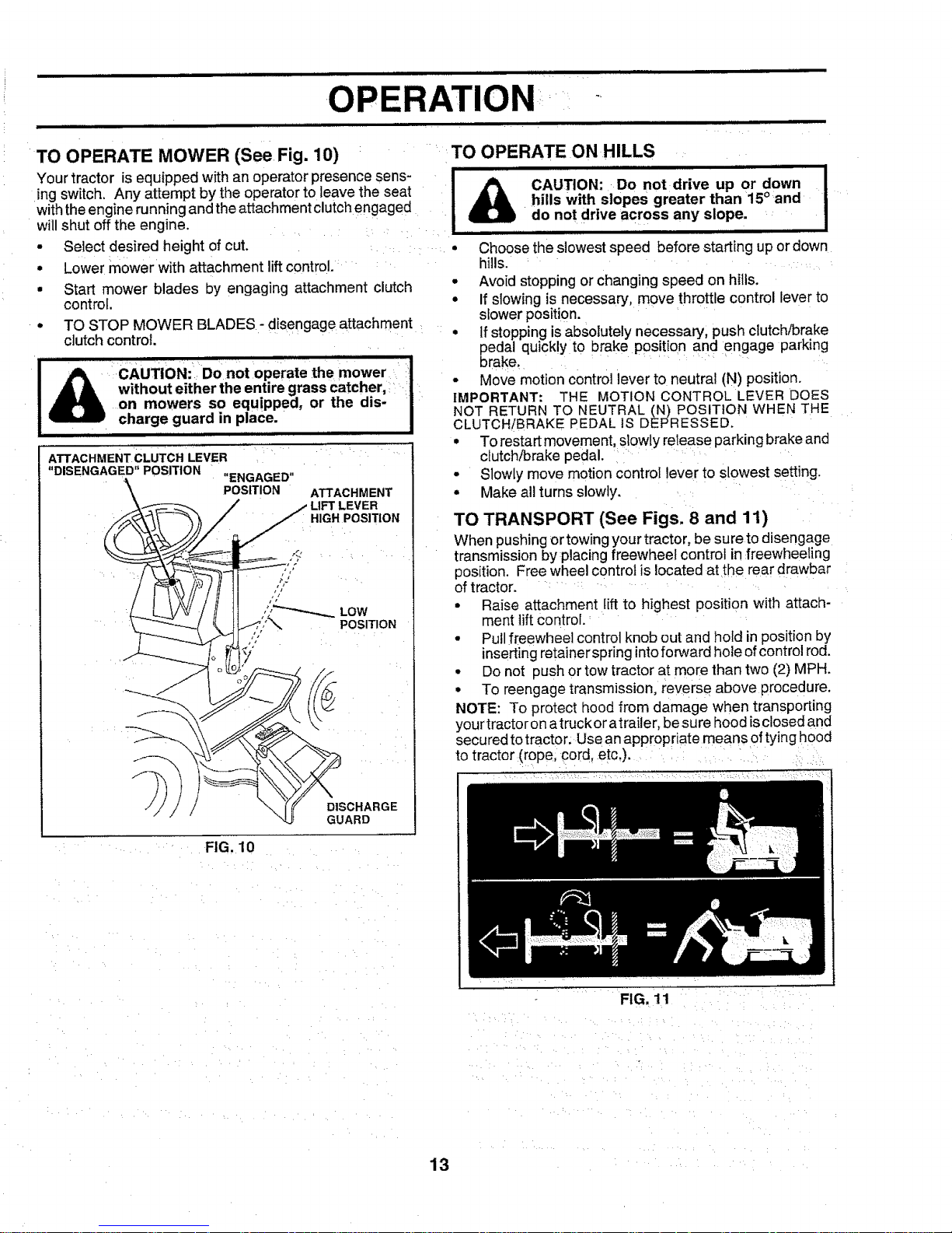
TO OPERATE MOWER (See Fig. 10) i
Your tractor is equipped with an operator presence sens-
ing switch. Any attempt by the operator to leave the seat
w th theengine running andthe attachment clutch engaged
will shut off the engine.
• Select desired height of cut.... .....
• Lower m0werwith attachment lift control. .....
• Start mower blades by engaging attachment clutch
control,
• TO STOP MOWER BLADES- disengage attachment
clutch control.
ATTACHMENT CLUTCH LEVER
"DISENGAGED" POSITION "ENGAGED"
• • '• • • H
POSITION ATTACHMENT
/ LIFT LEVER
__: HIGH POSITION
i /
II Low
i f'(" DISCHARGE
"-<Jr GUARD
FIG. 10
i,,lllHHIL
Illll
TO OPERATE ON HILLS
I
CAUTION: Do not drive up or down I
hills with slopes greater than 15°and I
do not drive ac,ross any slope. I
illll lll l i ,,,ll,i
Choose the slowest speed before starting up or down
hills. '
• Avoid stopping or changing speed on hills.
• If slowing is necessary, move throttle control lever to
slower position.,
• If stopping is absoIutely necessary, push clutch/brake
pedal quickly to brake position and engage parking
brake, ...... :
• MoVemotion control lever to neutral (N) position.
IMPORTANT: THE MOTION CONTROL LEVER DOES
NOT RETURN TO NEUTRAL (N) POSITION WHEN THE
CLUTCH!BRAKE PEDAL IS DEPRESSED.
• To restart movement, slowly release parking brake and
clutch/brake pedal. ....
• Slowly move motion control lever to slowest setting.
• Make all turns slowly.
TO TRANSPORT (See Figs, 8 and 11)
When pushing or towing your tractor, be sure to disengage
transmission by :placing freewheel control in :freewheeling
position. Free wheel control is located atthe rear drawbar
of tractor. : :....
• Raise attachment lift to highest position with attach-
ment lift control.:
• Pull freewheel control knob out and hold in position by
inserting retainer spring into forward hole ofcontrol rod.
• Do not push or tow tractor at more than two (2) MPH.
• To reengagetransmission, reverse above procedure.
NOTE: To protect hood from damage when transporting
yourtractor onatruckor atrailer, be sure hood isc osed and
secured totractor; Use an appropr atemeans of tying hood
to tractor(rope; cord, etc,)..... ........
FIG, 11
13
OPERATION
BEFORE STARTING THE ENGINE :: IMPORTANT: COLD STARTING FOR HYDRO (BELOW
...... 40 F) - AFTER STARTING ENGINE AND BEFORE
CHECK ENGINE OIL LEVEL (See Fig, 9) MINuTEDRIVING'BY PLACINGLET TRANSMISSIONMoTIoNWARMcoNTRoLUPFORLEvERONE(_)tN
The engine in your tractor has been shipped, fromthe :: : NEUTRAL (N) POSITION AND RELEASING CLUTCH/
factory, already filled with summer weight oil. ': ' BRAKE PEDAL.
* Check engine oil with tractor on level ground. NOTE; tf at a high altitude (above 3000 feet) or in cold
• Remove oil fiitcap/dipstick and wipe clean, reinsert the
dipstick and screw cap tight, wait for a few seconds,
remove and read oil level. If necessary, add oi1until
=FULL" mark on dipstick is reached. Do not overfill.
• For cotd weather operation you should change oil for
easier starting (See "OIL VISCOSITY CHART" in the
Customer Responsibilities section of this manual).
• To change engine oil, see the Customer Responsibili-
t es section n th s manual.
' : i: ii
ADD GASOLINE ....... '_
• Fill fuel tank. Use freshl clean, regular unleaded
gasoline. (Use of leaded gasoline will increase carbon
and lead oxide deposits and reduce valve life).
IMPORTANT: WHEN OPERATING IN TEMPERATURES
BELOW32°F(0°C), USE FRESH, CLEAN WINTER GRADE
GASOLINE TO HELP INSURE GOOD COLD WEATHER
STARTING, : ' '
WARNING:Experience indicates that alcohol blended
fuels (called gasohol or using ethanol or methanol) can
attract moisture which Ieads to separation andformation of
acids during storage. Acidic gas can damage the fuel
system of an engine while in storage. To avoid engine
problems, the fuet system should be emptied before stor-
age of 30 days or longer. Drain the gas tank, start the
engine and let it run until the fuel lines and carburetor are
empty. Use fresh fuel next season. See Storage Instruc-
tions for additional information. Never use engine or
carburetor cleaner products_ in the fuel tank or permanent
damage may occur,
[ _I k CAUTION: Fill tobottomofgasta'nk' i
• lki filler neck. Do not overfill. Wipe off any I
spilled oil or fuel. Do not store, spill or !
_iuse gasoline near an open flame. ...... !
I
i:iilii: :,i,! ii!¸i: ,ili i':iii ::i::;ii¸:i¸ ilii :ii:!ii
TO START ENGINE (See Fig. 9)
When starting engine loathe fi_t time:0r if engine !1asrun
out of:fuel,it Wi!l_akeextra cranking time to move fuel from
• brake:,
:Place motion control ::leverin neutral (N) position.i:
:Move attachment € utch'tO'"DISENGAGED" pos t On
• Move throttle control lever to choke (Xl) position for
cold engine start. Forwarm engine start, move thrott e
control to fast (,t_) position.
• Insertkey into ignitionandturn keyclockwise to"START"
position and release key as soon as engine starts. Do
temperatures (below 32°F), the carburetor fuel mixture
may need tobe adjusted for best engine performance. See
"TO ADJUST CARBURETOR" in the Service and Adjust-
ments section of this manual. _ ....
not run starter continuously for more than fifteen
seconds per minute. If engine does not start after
several attempts, move throttle control to fast (,t_)
position, wait a few minutes and try again.
When engine starts, slowly move throttle control lever
to desired running speed.
Allow engine to warm up for a few minutes before
engaging drive or attachments.
14
PURGE TRANSMISSION
................................ iii ,,,,, H H,I, ,I
............... CAUTION: Never engage or disengage i
':freewheel lever while the engine isrun- : |
nlng. _ : : I
To ensure proper operation and performance, it is recom-
mended that the transmission be purged before operating
tractor for the first time. This procedure wi!t :remove any
trapped air inside the transmission which may have devel-
oped during shipping of your tractor.
IMPORTANT: SHOULDYOUR TRANSMISSION REQUIRE
REMOVAL FOR SERVICE OR REPLACEMENT, IT
SHOULD BE PURGED AFTER REINSTALLATION
BEFORE OPERATING THE TRACTOR.
• Place tractor safely on level surface with engine off and
parking brake set.
• Disengage transmission by placing freewheel control
in freewheeling position (See '%0 TRANSPORT" in
this section of manual).
• Sitting inthe tractor seat, start engine. After the engine
is running, move throttle control to stow (,_) position.
With motion control lever in neutral (N) position, slowly
disengage clutch!brake pedal.
• Move motion control lever to full forward position and
hold for five (5) seconds. Move lever to full reverse
position and hold for five (5) seconds. Repeat this
procedure three (3) times.
NOTE: During this procedure there will be no movement of
drive wheels. The air is being removed from hydraulic drive
system.
• Move motion control lever to neutral (N)position. Shut-
off engine and set parking brake.
• Engage transmission by placing freewheel control in
driving position (See 'qO TRANSPORT" in this section
of manual).
• Sitting inthetractor seat, start engine. Afterthe engine
is running, move throttle control to half (1/2) speed.
With motion control lever in neutral (N) position, slowly
disengage clutch/brake pedal.
• Slowly move motion control tever forward, after the
tractor moves approximately five (5) feet, slowly move
motion control lever to reverse position. After the
tractor moves approximately five (5) feet return the
motion control lever to the neutral (N) position. Repeat
this procedure with the motion control lever three (3)
times.
• Your tractor is now purged and now ready for normal
operation.
...........................PERATION ':
................... ,,,,,, i iiii i
MOWING TIPS
• Tirechains cannot be used when the mower housing is
attached to tractor .....
° Mower should be ,properly leveled for best mow!ng
performance. See 'TOLEVEL MOWER HOUSING in
I
o
MULCHING MOWING TIPS
IMPORTANT: FOR BEST PERFORMANCE, KEEP
MOWER HOUSING FREE OF BUILT-UP GRASS AND
TRASH. CLEAN AFTER EACH USE.
the Service and Adjustments section of this manual.
The left hand side of mower should be used for trim-
ming.
Drive so that clippings are discharged onto the area
that has been cut. Have the cut area to the right ofthe
machine. This will result ina more even distribution of
clippings and more uniform cutting.
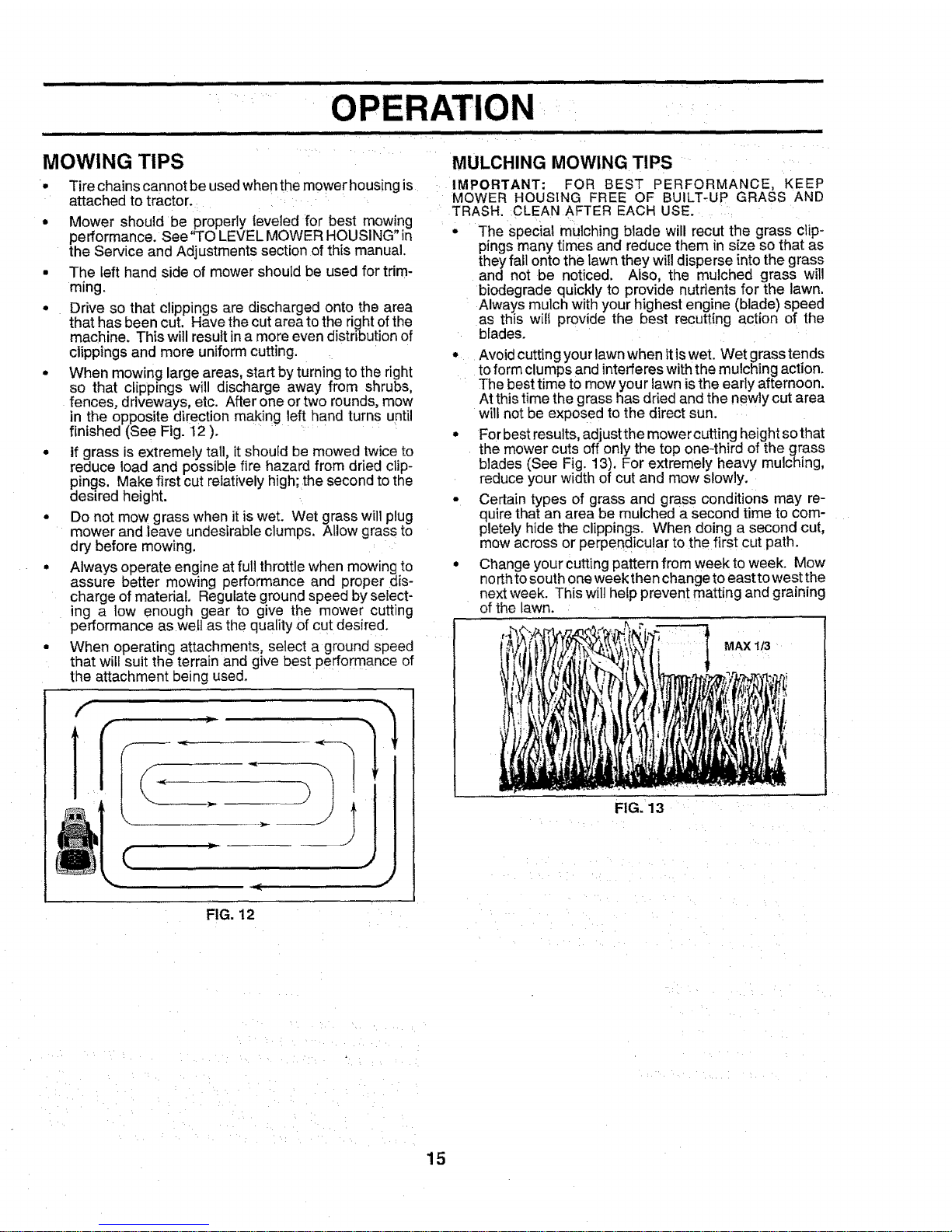
When mowing large areas, start by turning to the right
so that clippings will discharge away from shrubs,
fences, driveways, etc. After one or two rounds, mow
in the opposite di[ection making left hand turns until
finished (See Fig. 12 ). ............
If grass is extremely tail, it should be mowed twice to
reduce load and possible fire hazard from dried clip-
pings. Make first cut relatively high; the second to the
desired height.
Do not mow grass when it iswet. Wet grass willplug
mower and leave undesirable clumps. Allow grass to
dry before mowing.
Always operate engine at full throttle when mowing to
assure better mowing performance and proper dis-
charge of material. Regulate ground speed by select-
ing a low enough gear to give the mower cutting
performanceas wett as the quality of cut desired.
When operating attachments, select aground speed
that will suit the terrain and give best performance of
the attachment being used.
OH
The special mulching blade will recut the grass clip-
pings many times and reduce them in size so that as
they fall onto the lawn they will disperse into the grass
and not be noticed. Also, the mulched grass will
biodegrade quickly to provide nutrients for the lawn.
Always mulch with your highest engine (blade) speed
as this w I° provide the best recutting action of the
blades.
Avoid cutting your lawn when itis wet. Wet grasstends
toform clumps and interferes with the mulching action.
The best time to mow you r lawnis the early afternoon.
At this time the grass has dried and the newly cut area
will not be exposed to the direct sun.
For best results, adjustthe mowercutting height sothat
the mower cuts off only the top one-third of the grass
blades (See Fig. 13). For extremely heavy mulching,
reduce your width of cut and mow slowly.
Certain types of grass and grass conditions may re-
quire that an area be mulched a second time to com-
pletely hide the clippings. When doing a second cut,
mow across or perpendicular to the first cut path.
Change your cutting pattern from week to week. Mow
northto south one week then change to east to west the
next week. This wilt he!p prevent matting and graining
of the lawn ....
MAX 113
FIG. 13
FIG. 12
15
H,II'I I I IIll IIH,III,,,, nl inll Ullllll,i, i lllll i IIn II i I
CUSTOMER BILITIES
.... , ,, ,,,, ........................... ,,,,, ,,,,,,,,,,,,,,,,,, ,,,,, , ........................... ,,,,,, , lllllllllllllll , , ,,,,,,,,,,,,,,,,,,
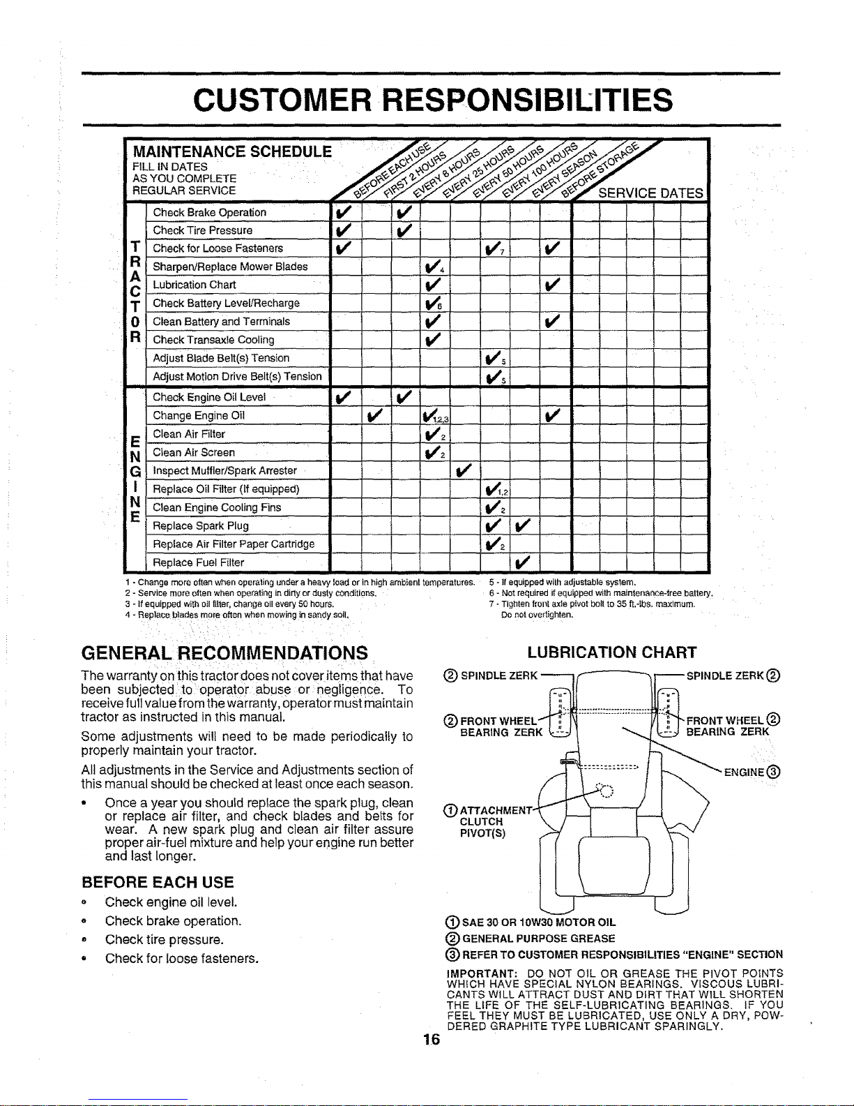
MAINTENANCE: SCHEDULE '''!':':'.,__ ..,_"'_..........................
AS YOU COMPLETE
REGULAR,SERVICE ._'__-//_._" SERVICE DATES
Check Brake Operation _i ......
Check Tire Pressure ..................
T Check for Loose Fasteners I/ 1_7 I_
R SharpervReP.!ace Mower Blade s i 1_4
C LuSrication Chart , _ ............. if
T Check Battery Level/Recharge !_B ......... .... I,,
0 Clean Battery and Terminals if I_
R Check_raosa×leCooling
Adjust Blade Belt(s) Tension Vf5
'Adjust Motion Drive Belt(s) Tension ...... lk_s ......
II
Check Engine OilLave1 If I if i
Change Engine Oil V _ tk_1,2,3 .................. V _ ......
E Clean Air Fi[ter V'2
N Clean Air Screen . 1_2
G InspeciM uffie r/Spark Arrestor 1_
I Replace Oil""Filter (If equipped) V_1,2
N *'CleanEngine cooling Fins : v*a .....
1=
Replace Spark Plug ............. " " If if "
Replace Air Filter Paper Cartridge ..........................Ik_2
.........,., p,aoe'Fuo,F,.tor t ..........I V
5 - If equipped with adjustable system.
6 - Not required if equipped with maintenance-free battery.
7 - Tighten front axle pivot bolt to 35 ft.-Ibs, maximum.
Do not overSghten.
1- Changemore0_enwhenoperatingunderaheavyloadorin highambienttemperatures.
2- Servicemoreoftenwhenoperating in dirtyor dusty conditions.
3- Ifeqaippedwithoilfilter,changeell every50hours.
4- Replaceb]adesmoreoftenwhenmowinginsandysoil.
i _ i ii:i_i_: i , i :
GENERAL RECOMMENDATIONS
The warranty onthis tractor does not cover items that have
been subjected:to:operator abuse or :negligence. To
receive full value from the Warranty,operat0r must maintai n
tractor as instructed in this manual. (_
Some adjustments will need to be made periodically to
properly maintain your tractor.
All adjustments in the Service and Adjustments section of
this manual should be checked at least once each season.
(_ SPINDLE
LUBRICATION CHART
BEARING ZERK
Once ayear you shouid repIace the spark plug, clean
or replace air filter, and check blades and hefts for (_ CLUTCH
wear. A new spark plug and clean air filter assure PIVOT(S)
proper air-fuel mixture and help your engine run better
and last longer.
n
®
-FRONT WHEEL (_
BEARING ZERK
IGINE®
BEFORE EACH USE
o Check engine oil level.
o Check brake operation.
o Check tire pressure.
• Check for loose fasteners.
16
(_ SAE 30 OR 10W30 MOTOR OIL
(_) GENERAL PURPOSE GREASE
® REFER TO CUSTOMER RESPONSIBILITIES "ENGINE"
SECTION
IMPORTANT: DO NOT O1L OR GREASE THE PIVOT POINTS
WHICH HAVE SPECIAL NYLON BEARINGS. VISCOUS LUBRI-
CANTS WILL ATTRACT DUST AND DIRT THAT WILL SHORTEN
THE LIFE OF THE SELF-LUBRICATING BEARINGS. IF YOU
FEEL THEY MUST BE LUBRICATED, USE ONLY A DRY, POW-
DERED GRAPHITE TYPE LUBRICANT SPARINGLY.
TRACTOR
Always obsewe safety rules when performing any mainte-
nance.
BRAKE OPERATION
If tractor requires more than six (6) feet stopping distance
athigh speed in highest gear, then brake must be adjusted.
(See "TO ADJUST BRAKE" in the Service and Adjust-
ments section of this manual), i:_::, ,:
TIRES
• Maintain proper air pressure in alt tires (See "PROD-
UCT SPECIFICATIONS" on page 3 of this manual).
• Keeptires free of gasoline, oil, or insectcontrol chemi-
cals which can harm rubber.
• Avoid stumps, stones, deep ruts, sharp objects and
other hazards that may cause tire damage.
BLADE CARE
For best results mower blades must be kept sharp. Re-
place bent or damaged blades. ..... :
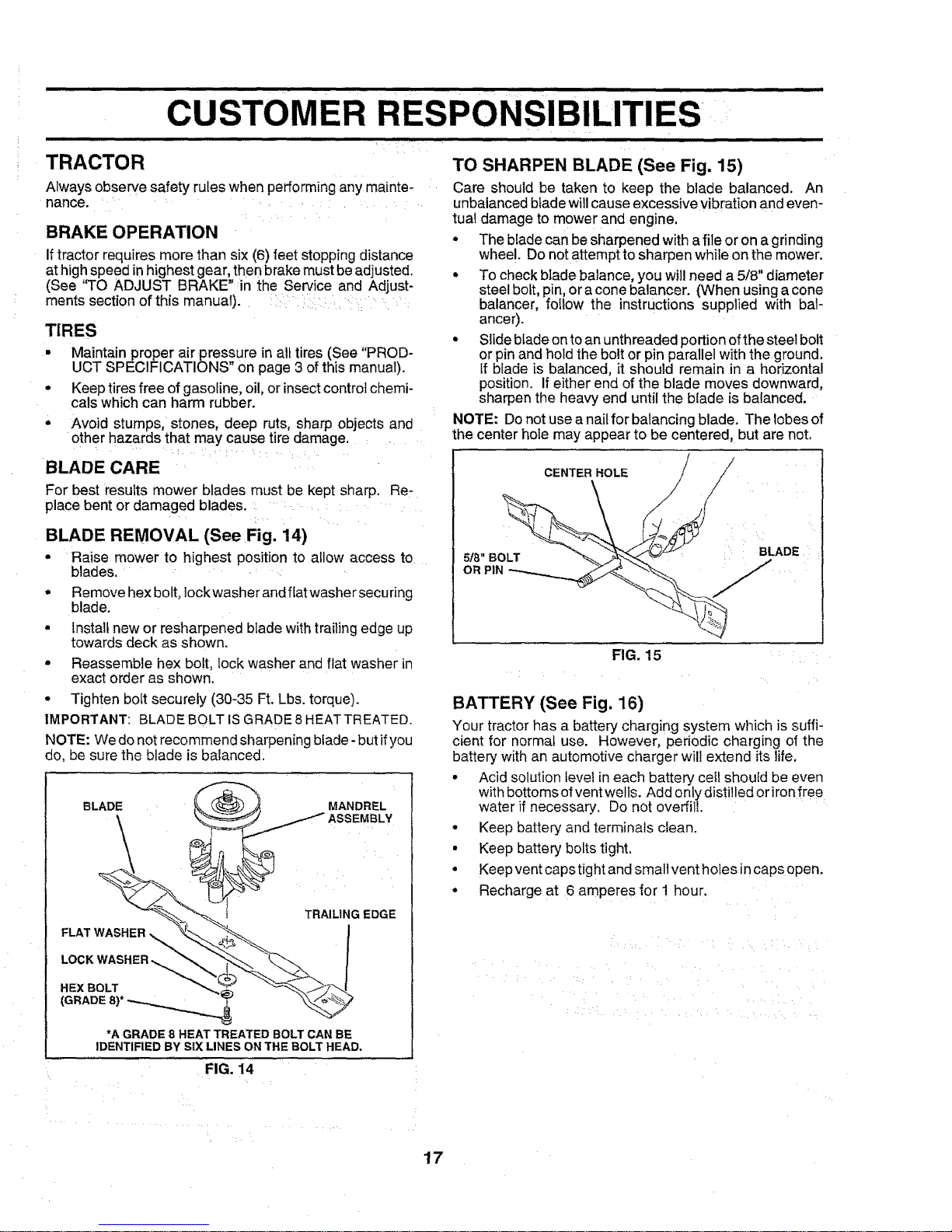
BLADE REMOVAL (See Fig. 14)
• Raise mower to highest position to allow access to
blades. ,
• Remove hex bolt, Iockwasher and flat washer securing
blade.
• Install new or resharpened blade with trailing edge up
towards deck as shown.
• Reassemble hex bolt lock washer and f at washer n
exact order as showi.
• Tighten bolt securely (30-35 Ft. Lbs. torque).
IMPORTANT: BLADE BOLT ISGRADE8HEATTREATED.
NOTE: We do not recommend sharpening blade -but ifyou
do, be sure the blade is balanced.
MANDREL
_ ASSEMBLY
TRAILING EDGE
FLAT WASHER ,!
*A GRADE 8 HEAT TREATED BOLT CAN BE
IDENTIFIED BY SIX LINES ON THE BOLT HEAD.
FIG. 14
TO SHARPEN BLADE (See Fig. 15)
Care should be taken to keep the blade balanced. An
unbalanced blade will cause excessive vibration and even-
tual damage to mower and engine,
• The blade can be sharpened with afile or on a grinding
wheel. Do not attempt to sharpen while onthe mower.
• To check blade balance, you will need a5/8" diameter
steel bolt, pin, or acone balancer. (When using a cone
balancer, follow the instructions supplied with bal-
ancer).
• Slideblade on to an unthreaded portion ofthe steel bolt
or pin and hold the bolt or pin parallel with the ground,
If blade is balanced, it should remain in a horizontal
position. Ifeither end of the blade moves downward,
sharpen the heavy end until the blade is balanced.
NOTE: Do not use a nail for balancing blade. The lobes of
he center hole may appear to be centered, but are not,
CENTERHOLE / /
- AOE
FIG. 15
BATTERY (See Fig. 16)
Your tractor has a battery charging system which is suffi-
cient for normal use. However, periodic charging of the
battery with an automotive charger will extend its life.
° Acid solution level in each battery cei! should be even
with bottomsof vent wells. Add onlydistilled oriron free
water if necessary. Do not overfill.
• Keep battery and terminals clean.
• Keep battery bolts tight,
• Keep vent caps tight and small vent holes incaps open.
• Recharge at 6 amperes for 1 hour.
17
iii i,i i i,nl,,Ul |lulllll iii ii i
USTOMERI RESPONSIBILITIES
ii1,11,111 i iii1,111,1 i i i i nl n lI n i,
TO CLEAN BATTERY AND TERMINALS
Corrosion and dirt on the battery and terminals can cause
the battery to "leak" power. :
• Open battery box door.
• Disconnect BLACK battery cable first then RED bat-
tery cable and remove battery from tractor.
• Wash battery with solution of four tablespoons of
baking soda to one gallon of water. Becareful nottoget
the soda solution into the cells.
• Rinse the battery with plain water and dry,
• Clean terminals and batterycable ends with wire brush
until bright. _....
• Coat terminals with grease or petroleum jelly.
• Reinstall battery (See "INSTALL BA-I-FERY" in the
Assembly section of this manual).
ENGINE
CUT AWAY VIEW
VENT
WELL
BATTERY
CELL ACID
LEVEL
FIG. 16
V-BELTS
Check V-belts for deterioration and wear after 100hours of
operation and replace if necessary. The belts are not
adjustable. Replace belts if they begin to slip from wear.
TRANSAXLE COOLING
The fan and cooling fins of transmission should be kept
clean to assure proper cooling.
Donot attempt to clean fan or transmission while engine is
running or while the transmission is hot.
• Inspect cooling fan to be sure fan blades are intact and
clean.
• _nspectcooling fins for dirt, grass clippings and other
materials. To prevent damage to seals, do not use
compressed air or high pressure sprayer to clean
cooling fins.
TRANSAXLE PUMP FLUID
The transaxle was sealed at the factory and fluid mainte-
nance is not required forthe life ofthetransaxle. Should the
transaxle ever leak or require servicing, contact your near-
est authorized service center/department.
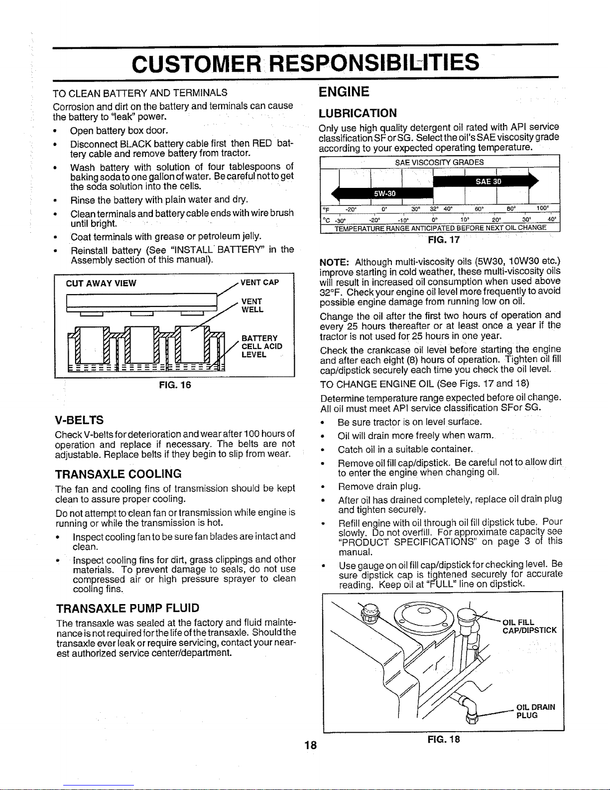
LUBRICATION
Only use high quality detergent oil rated with API service
classification SF orSG. Select the oil's SAE viscosity grade
according to your expected operating temperature,
'"'"SAE VISCOSITY GRADES
r
..............J..........
C.F _20_ 0o 30_ 32 ° 40 ° 60 ° 80_' 100 _'
°C -30`= -20 = .t0 o 0 ° 1_0_ 20° 30" 40 =
TEMPERATURE RANGE ANTICIPATE[) BEFORIE NEXT OIL CHANGE
FIG. 17 ........
NOTE: Although multi-viscosity oils (5W30, 10W30 etc.)
improve starting in cold weather, these multi-viscosity oils
will result in increased oil consumption when used above
32°F, Check your engine oil level more frequently to avoid
possible engine damage from running low on oil.
Change the oil after the first two hours of operation and
every 25 hours thereafter or at least once a year if the
tractor is not used for 25 hours in one year.
Check the crankcase oil level before starting the engine
and after each eight (8) hours of operation, Tighten oi! fill
cap/dipstick securely each time you check the oil level.
TO CHANGE ENGINE OIL (See Figs. 17 and 18)
Determine temperature range expected before oil change.
All oil must meet AP1service classification SFor SG.
• Be sure tractor is on level surface.
• Oil wilt drain more freely when warm.
• Catch oil in a suitable container.
° Remove oil fill cap/dipstick. Be careful not to allow dirt
to enter the engine when changing oil.
• Remove drain plug.
° After oil has drained completely, replace oil drain plug
and tighten securely.
• Refill engine with oil through oil fill dipstick tube. Pour
slowly. Do not overfill. For approximate capacity see
"PRODUCT SPECIFICATIONS" on page 3 of this
manual.
• Use gauge on oil fill cap/dipstick for checking level. Be
sure dipstick cap is tightened securely for accurate
reading. Keep oil at "FULL" line on dipstick.
. FILL
CAP/DIPSTICK
OIL DRAIN
PLUG
FIG. t8
18
 Loading...