

Sears Craftsman 917.251561 Owner's Manual
CRIIFTSMnN+
MODEL NUMBER 917.251561 OWNER'SMANUAL
• Assembly
• Operation
" Customer Responsibilities
• Service and Adjustments
• Repair Parts
CAUTION: Read and follow all safety rules and instructions before operating this equipment.
FOR CONSUMER ASSrSTANCE HOT LINE, CALL TH_S TOLL FREE NUMBER: 1-B00-659-5917
................... II IIIII I I
im
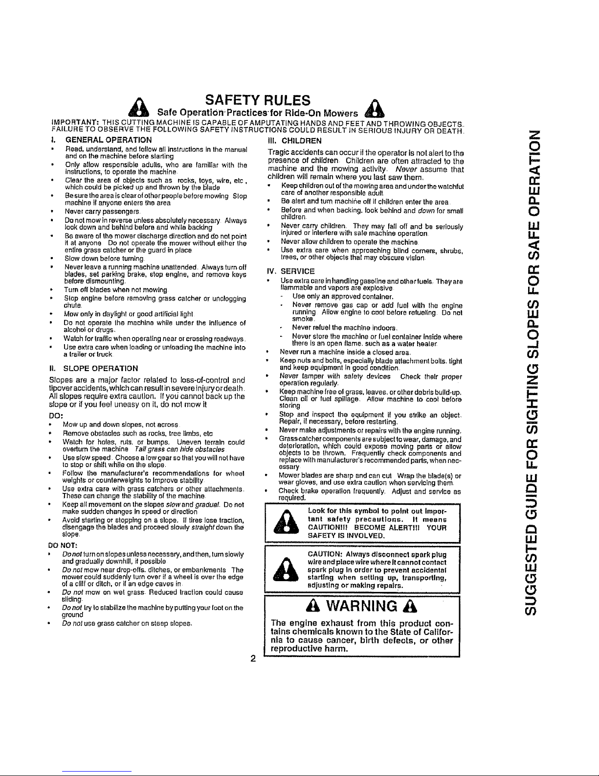
SAFETY RULES
Safe OperatiOn?ractices-for Ride-On Mowers
IMPORTANT: THIS CUTTING MACHINE IS CAPABLE OF AMPUTATING HANDS AND FEET AND THROWING OBJECTS.,
FAILURE TO OBSERVE THE FOLLOWING SAFETY INSTRUCTIONS COULD RESULT IN SERIOUS iNJURY OR DEATH,
L GENERAL OPERATION iii. CHILDREN
Reed, understand, and to_low a_linstructions In the manual Tragic accidents can occur it the operator is not alert to Ihe
and on the machine before slatting presence of chlIdren Children are often attracted to the
Only allow responsible adul[s, who are familiar with the machine and the mowing actMty Never assume that
instructions, to operate the machine
children wH! remain where you last saw them.
C{ear the area of ob ects such as rocks, toys wire, etc,
which could be pcked up and {1rowe by the b ads Keep children Out of the mowing area and under the watchful
Be sure the area Is clear of other people before mowing Slop
machine if anyone enters the area
• Never carry passengers
• Do not mow tn reverse unless absolutely necessary Nways
look down and behind balers end while becking
Be aware of the mower discharge direction and do not point
it at anyone Do not operate the mower without either the
entire grass catcher or lhe guard in place
. Stow down before tumlng
• Never leave a running maohtne unattended, Always tu re elf
blades, sat parking brake, stop engine, and remove keys
before dlsmountlng,
• Turn off blades when not mowing
• Stop engine before removing grass calcher or unclogging
chute
Mow only in daylight or good artificial light
• Do not operate Iha machine while under the influence of
alcohol or drugs.
• Watch for Iraflte when operating near or crossing roadways
Use extra care when loading or unloading the machine into
a trailer or Iruck
IL SLOPE OPERATION
Slopes are a major factor related Io loss-of-control and
tipover accidents, whlch can result in save re Injury or deafh
All slopes require extra caution, ff yotJ cannot back up the
slope or if you feel uneasy on It, do nol mow it
DO.
" Mow up and down slopes, not across
,, Remove obstacles such as rocks, tree limbs, ate
• Watch lot holes, ruts, or bumps. Uneven terrain could
overturn the machine Tallgrasscanhideobstscfes
• Use slow speed Choose a low gear so lhat you will not have
to stop or shill while on the slope.
Follow the manufacturer's recommendations for whee!
weights or counterweights to Improve slabiltty
. USa extra care wt[h grass catchers or other at.tachments
These can change the stability of the machine
, Kaepalimevamantonthesfopeestowandgraduaf, Donut
make sadden changes In speed or direction
Avoid staffing Dr stopping on a slope. It tires lose traction,
disengage the blades and proceed slowly straight down the
slope,
DO NOT:
. Do not turn on slopes unless necessary, and then, turn slowly
and gradually downhill, if possible
• Do not mew near drop-otis, ditches, or embankments The
mower could suddenly turn over if a wheel Is over the edge
o! a cltlf or ditch, or il an edge caves in
Do not mow on wel grass. Reduced traction could cause
eliding
• Do not hy to stabilize the machine by putting your loot on the
ground
• Do not use grass catcher on steep slopes,
t,
=,
e
care of another responsible adult
• Be alert and turn machir_e og tf children enter the ares
Before and when backing, took behind and down for small
children
• Never carry children They may fall off and be seriously
injured or interfere with sale machine operation
• Never allow children to operate the machine
• Use extra care when approaching blindcornea shrubs,
trees, or other objects thai may obscure vision
IV. SERVICE
Use extra care in handling gasoiine and otherfuels, They ara
flammable and vapors are explosive
Use only an approved container,
Never remove gas cap or add fuel wtlh the engine
running Allow engine to cool belora refueling Do not
smoke,
- Never refuel the machine indoors
Never store the machine or fuel conlatner inside where
there ls an open flame, such as a water heater
Never run a machine inside a closed area.
Keep nuts and bolts, especially blade attachment bolts, tight
and keep equipment in good condition
Never leaper wilh safely devices Check their proper
operation regularly.
Keep machfne free el grass leaves, orother debris build-up.
C san oil or fuel spillage Allow machine to coot before
alodng
Stop end inspect the equipment if you strike an obiect
Repair, il necessan/, before restarting,
Never make adjustments or repairs with tire engine running,
Graescatcher components are sub eel to wear damage, and
deterioration, whfeh could expose moving parts or allow
objects to be throwm Frequently check components and
replace with manuiacturer's recommended pads, when nec-
essary
Mower blades are sharp and can cut Wrap the b}ade s) or
wear gloves, and use extra caution when servicing them
Check brake operation frequently Adjust and service as
required,
Look for IhI8 symbol to point out Impor-
tant safety precautions. It means
CAUTION|If BECOME ALERTIII YOUR
SAFETY IS INVOLVED.
CAUTION: Always disconnect spark plug
wire end place wtre where It cannot contact
spark plug in order to prevent eccldentsl
starting when setting up, transpodlng_
adjustEng or making repair s.
WARNING &
The engine exhaust from this product con-
tains chemicals known to the State of Califor-
nia to cause cancer, birth defects, or other
reproductive harm.
rr
LU
I.g
14.
n-
O
LI.
O3
UJ
O
...J
O3
(5
Z
m
I--
-!-
(5
m
or)
u=
ILl
!:3
I-,
o9
uJ
(5
(5
o3
CONGRATULATIONS on your purchase of a Sears
Tractor tt has been designed, englheered and manufac..
tured to give you the best possible dependability and
pefformance_
Should you experience any problem you cannot easily
remedy, please contac! your nearest Sears Authorized
Service centedDepadment Department. We have com-
petent, welt-trained technicians and the.proper tools to
service 0_"repair thts tractor.
Please read and retain this manual The inskuctions will
enable you to assemble and maintain your tractorproperly]
Always observe the "SAFETY RULES"
MODEL
NUMBER 917 25t 56t
SERIAL
NUMBER
DATEOFPURCHASE
THE MODELAND SERIAL NUMBERS WILL BE FOUND
ON A pLATE UNDER THE SEAT
YOU SHOULD RECORD BOTH SERIAL NUMBER AND
DATE OF PURCHASE AND KEEP IN A SAFE PLACE
FOR FUTURE REFERENCE..
MAINTENANCE AGREEMENT
.ASears Maintenance Agreement ls available on _hisprod_
uct ContacJ your nearest Sears store for de|&its
CUSTOMER RESPONSIBILITIES
• Read and observe the safety rules
• Fol!ow a regutar schedule in maintaining caring ferand
using your tractor '
- Foitow the instruct_onsunder "Customer Responsibili-
ties" and "Storage'* sections of this owner's manual
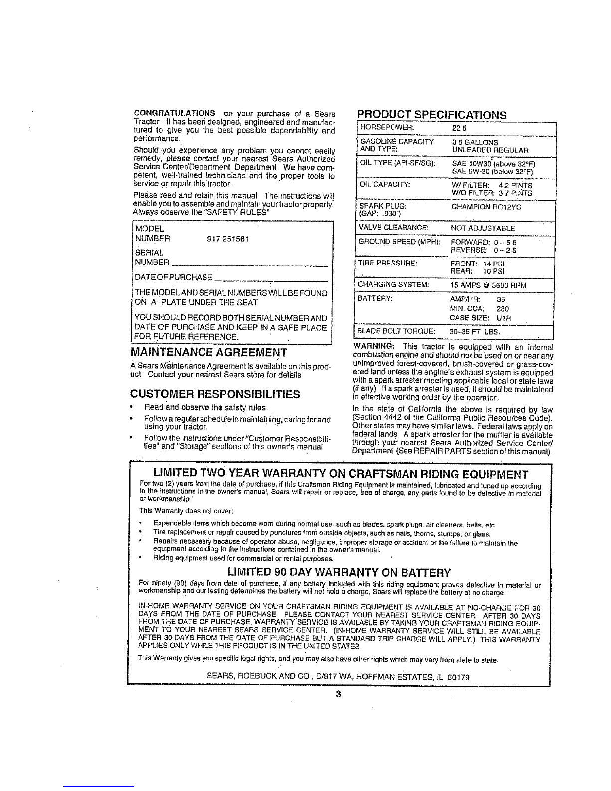
PRODUCT SPECIFICATIONS
HORSEPOWER: 22 5
GASOLINE CAPACITY 3 5 GALLONS
AND TYPE: UNLEADED REGULAR
OIL TYPE (API_SF/SG): SAE toW30'(above 32"F)
SAE 5W-30 (batew 32_F)
O_LCAPACITY: W!FILTER: 42 PINTS
W/O FILTER: 3 7 PINTS
SPARK PLUG: CHAMPION RC12YC
(GAP- .030")
VALVE CLEARANCE: NOT ADJUSTABLE
GROUND SPEED (MPH): FORWARD; 0 - 56
REVERSE; 0-25
TIRE PRESSURE: FRONT: 14 PSi
REAR: I0 PSI
CHARGING SYSTEM: 15 AMPS @ 3600 RPM
BATTERY'. AMP/HR: 35
MfN CCA; 280
CASE SIZE: UtR
BLADE BOLT TORQUE: 30.-35 FT LBS.
WARNING: This Iractor is equipped with an internal
combustion engine and should not be'used on or near any
unimproved torest-.covered, brush-covered or grass-cov-
ered land unless the engine's exhaust system is equipped
wilh a spark attester meeting applicable local or state taws
(if any) If a spark arrestor isused, tt should be maintained
in effective working order by lhe operatOr.r
in the state of California the above Is required by law
(Section 4442 ol the California Public Resources Code).
Other states may have similar taws Federal iaws apply on
federal lands A spark arrestor for the muffler is available
through youi" nearest Sears Aulhorized Service Center/
Department (See REPAIR PARTS section ol this manua )
, H,,,i i
LIMITED TWO YEAR WARRANTY ON CRAFTSMAN RIDING EQUIPMENT
For two (2) years from Ihedate of purchase if thisCraftsman R_dtngEquipment telmainla ned, ubficated and laned up according
to fhe instructions in the ewnePs manuaF_Sears wll!repair or replace, tree of charge, any partsfound to be detective in maledal
or Workmanship '
This Warranty does natcover.
Expendable ilems which become worn dadng normal use such as blades, spark plugs• air cleaners, bells, elc
" Tirereplacementor repair caused by puncturesfrom outside objecls, such asnails, thorns, stumps, or gtass
• Repa|ts neeesse_ because ofoperator abuse, negligence, improperstorage or accident or 4hafailure to maintain the
equipment according to thelnstruction_ containedtn the owner's manual
Riding equipmenlused for commercialor _nlal purposes.
LIMITED 90 DAY WARRANTY ON BATTERY
For ninety (90) days from date of purchase, if any batlen/]ncruded with ths rid ng equipment proves defecllve in matedal or
workmanship and ourtesting determines thebalten/will not hold a charge, Searswt_ireplacethe bat ery a! no charge
IN-HOME WARRANTY SERVICE ON YOUR CRAFTSMAN RIDING EQUIPMENT IS AVAILABLE AT NO-CHARGE FOR 30
DAYS FROM THE DATE OF PURCHASE PLEASE CONTACT YOUR NEAREST SERVICE CENTER. AFTER 30 DAYS
FROM THE DATE OF PURCHASE, WARRANTY'SERVICE IS AVAILABLE BY TAKING YOUR CRAFTSMAN RIDING EQUIP-
MENT TO YOUR NEAREST SEARS SERVICE CENTER, (IN-HOME WARRANTY SERVICE WILL STILL BE AVAILABLE
AFTER 30 DAYS FROM THE DATE OF' PURCHASE BUT A STANDARD TRIP CHARGE WiLL APPLY ) THIS WARRANTY
APPLIES ONLY WHILE THIS PRODUCT IS IN THE UNITED STATES
This _/artanty gives you specIflc legal rights, end you may also have otherrightswhich may van/from state to stale
SEARS, ROEBUCK AND CO, Dt817 WA, HOFFMAN ESTATES, iL 60179
! , t ,1 = ,,,,i HH I
3
SAFETY RULES ........ ;....... _............................................. 2
PRODUCT SPECtFtCATIONS.....,:._ ....... _...._..o...; ...... 3
CUSTOMER RESPONSIBILITIES .......................... 3, 16-19
WARRANT'Y _...: .................................... _............................. 3
TRACTOR ACCESSORIES ....................................... 5,15
ASSEMBLY" ..................................... i.......................... 7-t0
OPERATION ......... ,:............................................... _....... t2-16
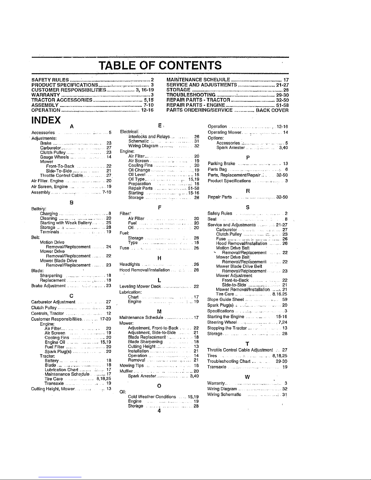
TABLE OF CONTENTS
MAINTENANCE SCHEDULE ..o: .................................. 17
SERVICE AND ADJUSTMENTS ............................. 21-27
STORAGE ....... _._................................................................ 28
TROUBLESHOOTING ............... :..................... ,..... 29-30
REPAIR PARTS - TRACTOR .............................. _ 32-50
REPAIR PARTS- ENGINE ........................................ 51-58
PARTS ORDERING/SERVICE ............... BACK COVER
INDEX
A
Accessories ....................... ;......... 5
Adjustments;
Brake ........................................ 23
Carbu_'eter .......................... 27
Clutch Putley ........................... 23
Gauge Wheels ............. t 4
Mower
Front*To-Back .................. 22
Side-To-Side ................... 21
Threltle Control Cable. .......... 27
Air Filler. Eng!ee ............................ 20
Air Screen, Engine .......... ; 19
Assembly ............................... 7.10
B
Battery:
Charging .............................. 8
Cleaning ................................. 20
Starting wilh Weak Bailer,/ ..... 25
Storage., .= .......... : ................ 28
Terminals ........ :..... t9
Belt:
Motieh Ddve
RemovaL/Replacement ........ 24
Mower Drive
Remeva_Replecemenl ......... 22
Mower Blade Drive
RemovaltReplsoement ........ 23
Blade:
Sharpening ........................... 18
Replacement ............... _ m ....... 18
Brake Adjustment ............. : ............ 23
C
Carburetor Adjustment .......... 27
Clutch Pulley ................... :...... 23
Conlrola, Tractor .................. :. 12
Cuslomer Responsibilities ........ 17-20
Engine:
Air Filter........................ 20
Air Screen ........................ 19
CscItng Eins ..... : ............. 20
Engine OII ...................... t5,19
Fuel Filter ......................... 20
Spark Ping(s) ............ 20
Tractor:.
BatterY ........... : ...... tB
Blade ....... .................. 18
Lubrication Chad .......... ;:,:...... 17
Maintenance Schedule ....... _., 17
Tire Care ......................&tB,25
Trsnssxle ................... 19
Culling Height, Mower ............... 13
E_
Etectrtcati
Interlocks and Relays .......... 26
Schematic ;........................ 3t
Wiring Diagram .................. 32
Engine:
Air Filler .................... 20
Atr Screen .......................... t9
Cooling Fins .................................20
OIl Change ...................... 19
Oil Level ............................. 15
Oil Type ...... ; ................. 15,19
Preparation .......... ',..... : 15
Repair Pads ...................... 51-58
Starting ................ _ ,, ,15-16
Storage ..... _......... : ........... 28
F
Filter:'
Air Filler .......................... 20
Fuel ................................... 20
Oil.........................................20
Fuel:
Storage ......................... 28
Type ............................ , 15
Fuse , ,........................ 26
H
Headlights ............................. 26
Hood Removal/lnstaliation ..... : :, , 26
L
Leveling Mower Deck .................... 22
Lubdcalion:
Chan ..................................... 17
Engine ........................... t9
M
Matnlenanee Scheduie ..................... I7
Mower:
Adjustment, Front4e..Back. ..... 22
Adjustment, Side-4o-Side ...... 2.1
Blade Replacement .............. 18
Blade Sharpening ..... 18
Cutting Height ..:................. !3
installation ...................... 21
Operatisn _...................... t4
Remdval ............... _... .. 2t
Mowing TIps _................... 16
Muffler ..................... : ..... 20
Spark Arrestor ...................... 3,40
Oil:
O
Cold Weather Conditions ..... 15,19
Engine ......................... 19
Storage .............................. 2B
4
Operallsn ............................. , 12-16
Operating Mower . : .... ............ 14
Options:
Accessories ,: ................. , ...........5
Spark Arrestor ..........:.: ........ 3,40
P
Paddng Brake .................... , .... 13
Paris Bag ........ _,, .,,: .................... :* 6
Pads, ReplacemenVRepair.:. 32-50
Product Specifications ................. 3
R
Repair Parts ............................. 32-50
s
Safely Rules ........................ 2
Seat ............... , .... : B
Service end Adjuslment8 ..... , 21-27
Carburetor :...... ...... _ , 27
Clutch Pulley ................ ;::. _..... 23
FUSe .............. ;_,;, .......... : ........ 26
Hood Remova!/Inst@llatien ........... 26
Motion Ddve Belt
'_ Removal/Replacement .... 22
Mower Drive Belt"
Removal/Reprasemeni ...... 22
Mower Blade Drive Belt
Removal/Replacement • . 23
Mower Adjustmef_t
Froat-lo-Bsck ........... ......... 22
Side-to-Side' ................... :, 21
Mower RemovaVtnstallaiFon ....... ;. 21
Tire Care ........... _.............. 8.16.25
Slope Guide Sheet ................... 59
Spark Plug(s) ,; r ,_ ................. 20
Specifications ....... :................. 3
Starting the Engine .......... 15-16
SteedngWheel ,, ........... 1..., ,7,24
Stopping the Tractor ........... 13
Storage ........................................ 26
T
Throtile Control Cable AdjUstment ', 27
Tires .................................... 8,1B,25
TroubleshootingChart ...... 29..30
Transaxle ..... ............. ..... 19
W
Warranty ............................. : . 3
Wiring Diagram ................................... 32
Wiring Schematic ................. : 3!
ACCESSORIES AND ATTACHMENTS
111 ,111 1 i1 , i • :L
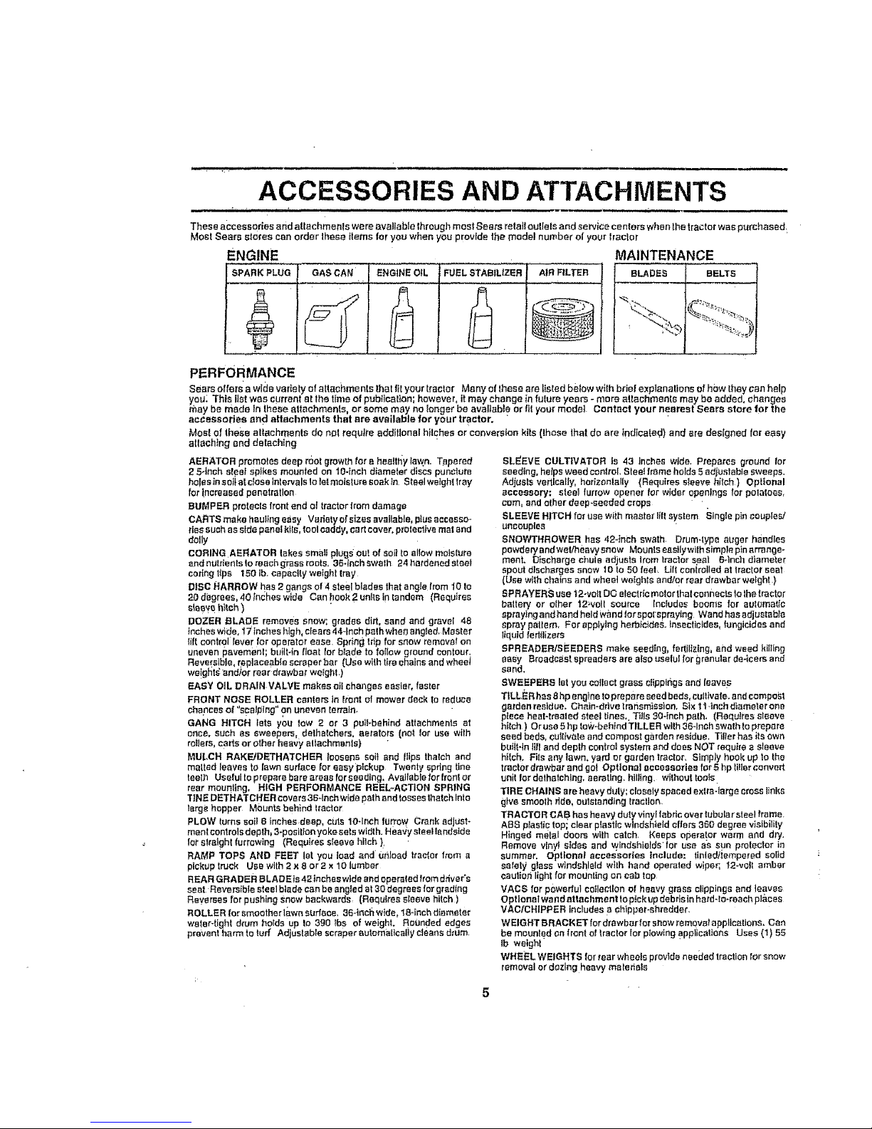
These accessories end attachme n!s we re r_vailable through most .Seam retail outlets and ae trice centers when the tractor was purchased;
Most Sears stores can order these Items for you when you provide the model number el your tractor
ENGINE MAINTENANCE
BLADES BELTS
PERFORMANCE
FUEL STABILIZER AtR FILTER
Sesrs offers'awida varietyofsttachments thatflt your traetor Many of these are lisled betoww_thbriefexplanattons ef how theycanhelp
you; This tlstwas currentat the timeof pobflcalion; however, it may changeinfuIure years - more attachments may be added, changes
they be made In theseattachments, or somemay no longer be available or tit yourmodet Contact your nearest Sears store for the
accessories and attachments that are available for your tractor.
Most of these altachments do not requl_eadditionalhitchesor conversionkits (those that do are indicated)and ere designed for easy
attaching and detaching
AERATOR promotes deep reel growth for e healtr_y la_n. Tapered
2 54nch sleet spikes mounted on 104nob diameter discs punciure
holes insoit st dose Inlervais to tel moisture soak tn Stselweighttray
fortrnCreaaedpenetration
BUMPER protects front end of tractor from damage
CARTS make hautfng easy Vadety of sizes avallab!e, pius accesso-
ries such as side panel kits, foolcaddy, cart cover, proteclJve mat and
doily
CORING AERATOR takes smaii plugs out of soilto allow moisture
and nuidenls to reach grsss roots, 36-inch swath 24 hardened steel
codng tips 150 lb. capacity weight trsy
DISC HARROW has 2 gangs of 4 steel blades that angle from 10 to
20 degrees, 40 _nches wide Can hook 2 units in tandem (Requires
sleey_h_ch )
DOZER BLADE removes snow; grades dirt, sand sod gravel 48
Inches wtde, 17Inches high, clears 44-inch path whe_ angled, Master
i_ftcontrol lever Ior operefer ease Spring frtp for snow remover on
uneven I_avement; buiiNn float for blade to foliow ground contour,
Reversible, replaceable scraper bar (Use with tire chains and wheet
we!g_ts'lsn_or rear drawbat welght_)
EASY OIL DRAIN VALVE makes ell changes easier, faster
FRONT NOSE ROLLER canters In trent of mower deck to reduce
chances o! "scslptng" on uneven lerraln_
GANG HITCH lets you tow 2 or 3 pull-behind attachments at
once, such as sweepers, delhatchers, aerators (not Ior use with
rollers ca_e or other heavy attachmenls)
MULCH RAKFJDETHATCHER loosens eoif end Itips thalch and
matted {saves to lawn surface lot easy pickup Twenty spdng tine
teelh Useful to prepare bare areas for seeding, Available for tronl or
rear mounting, HIGH PERFORMANCE REEL-ACTION SPRING
TINE DETHATCHER covers 36qnch wlde path end losses thatch Into
large hopper Mounts behind tractor
PLOW turns soil 6 inches deep, cuts t 0-Inch farrow Crank adjust-
meet controls deplh_ 3-position yoke sets width. Hea'Jy sleeHendside
lot slralght furrowing (Requires sleeve hllch }
RAMP TOPS AND FEET let you 10ad and unlcad Itactm" from a
pickup truck Use with 2 x 8 or 2 x 10 lumber
REAR GRADER B LAD E is 42 Inches wlde and operated from ddve r's
seat Reversible steel blade can be angled at 30 degrees for g_adtng
Reverses for pushing Snow backwards (Requires sleeve hitch )
ROLLER [or smoother t'_,v,,'neudar._, 36_Inch wlde, 1Soinch diameter
water-tight drum he{de up to 390 }bs of weight. Rounded edges
prevent harm to tuff Adjustable scraper automatically cleans drum
SLEEVE CULTIVATOR Is 43 inches wide, Prepares ground for
seeding, helps weed control Sloe! frame holds 5 edtuslsble sweeps,
Adjusts vertically, horizontally (Requires sleeve hitch ) Optional
accessory: steel furrow opener tot wider openings for potaloes,
cam, and other deep-seeded crops
SLEEVE HITC H for use wiih master till system Stngts pin couples/
uncauptss
SNOWTHROWER has 42-inch swath Drum-type auger h_ndles
powdery and welrneavy snow Mounts esstlywtlh simpie pin srrsnge-
ment. Discharge chute adjusts Irom tractor s._st E-inch diameter
spout dtscharges snow to to 50 feet Lift controlled at tractor sest
(Use with chains and who et weights end/or rear drawbar welghl )
SPRAYERS use 12-volt DC electdc meier thai connects 1othe tractor
battery or other 12welt source Includes booms for automatic
spraying and hand held wand ior spotspraytng Wend has adjustable
spray pattern, For applying herbicides. Insecticides, fungicides and
tiqutd fedilizers
SPREADERISEEDERS make seeding, fertilizing, and weed killing
BaBy Ercado_stspresdarsarsatsouselultorgrenularde-icersand
sand•
SWEEPERS let you collect grass cIipplhgs and {eave s
TILLER has 8 hpengtne topmpsre seed beds, cullivste, and compost
garden residue. Chain-drive transmission. Six I t ,inch dtameler one
piece heat-trsaled steel tines,, Tills 304nch path, (Requires sleeve
h_{ch ) Or use 5 hp to',;v-behtndTILLER with 36qnsh swath to prepare
seed beds, cultFvatesod compost garden residue. Tiller has its own
built-to Jill and depth oontroI system and does NOT require e sleeve
hIlch, Fits any lawn, yard or garden tractor, Simply hook up 1othe
tractor drswbar end gel Optional accessories for 5 hp tilter convert
unit lor dethstching, aerating, hiUing Without toots
TIRE CHAINS are heavy duty; closely spaced exlra.iarge cross links
give smooth ride, oulstandtng tracfton
TRACTOR CA B has heavy duty vinyl fabric overtubular steel frame.
ABe ptasfic top; clear plastic windshield offers 380 degree vlsibility
Hinged metal doors with cstch, Keeps operator warm and dry.
Remove vinyl sides and windshields'for use o's sun prolecter in
summer, Optional accessories Include: lintedltempered solid
sorely glass windshield wilh hand operated wiper; ?2-vstt amber
caulionlightfsr mounting on cab fop
VACS for powerful collection of heavy grass clippings end teaves
Opt lonst wand attachment to pick up dab rJsin hard-!o-roach pl&ees
VAO/CHIPPER includes s chipper-shredder.
WEIGHT BRACKET lor drawber for snow remqve/appl_catlona, Can
be mounted on f reel el tractor {orplowing applications Uses (1) 55
Ib weight
WHEEL WEIGHTS for tear wheels provide needed traction Tot snow
removal or dozing heavy ma_etists

CONTENTS OF HARDWARE PACK
Parts Bag contents Shown full size
(1) Knob
(1) Shoulder Bolt
5/!6qB
(1) Washer 17/32 x 1-3/t6 x 12 Gauge
/(_ (3) Re,ainer Springs (doub|e ,oop)
4) Retainer Springs (single loop) _'
(_etoiner Springs .
io" l!
(4) Clovis P_n_
J. t i
(2) Hex Bolts 1t4-20 x 3/4
(2) Hex Nuts 114-20
@ ®
(2) Lock Washers 1,/4
(2) W_shers 9/32 x 5/8 x 16 Gauge
Parts packed separately in carton
Steering
Wheel
Manual
Seat
Video
Cassetle
J,,
Steering
Sleeve Parts Bag
*" t , ,
Parts bag contents not shown full size
_ /"¢""-'_ _ (2)Washers 3;'a
_i;) Fron,t,n,,Assemb,,es_'
Steering C
Wheel
Insert
(2) Keys
Slope Sheet
ASSEMBLY
YOU_"new tractor has been assembled at the factory wit" the exception ofthOSeparis le_ssembled for shipping purp0ses_.
To ensure safe and proper operation of your tractor all paris and hardware you assemble must be tightened Securefy.. Use
the cor'rect tools as necessary to insure proper tightness. '
TOOLS REQUIRED FOR ASSEMBLY
A socket Wrench set wilt make assembly easier Standard
wrench sizes are listed
(2) 7/16" wrenches Tire pressure gauge
(1) 1/2" wrench Utflity knife
(1) 9/16" wrench
(t) 3/4_' socket with drive ratchet
When i'ight or left hand Is mentioned in fhls manual, it
means when you are in the operating position (seated
behind the steering wheel)
TO REMOVETRACTOR FROM CARTON
UNPACK CARTON
• Remove atl accessible loose parts and parts cartons
from carton (See page 6)
,' Cut, from top Io bottom, along lines on all four corners
of carton, and toy panels fla!.
" Remove mower and packing materials
• Check for any additional loose parts or cartons and
remove
BEFORE ROLLING TRACTOR OFF SKID
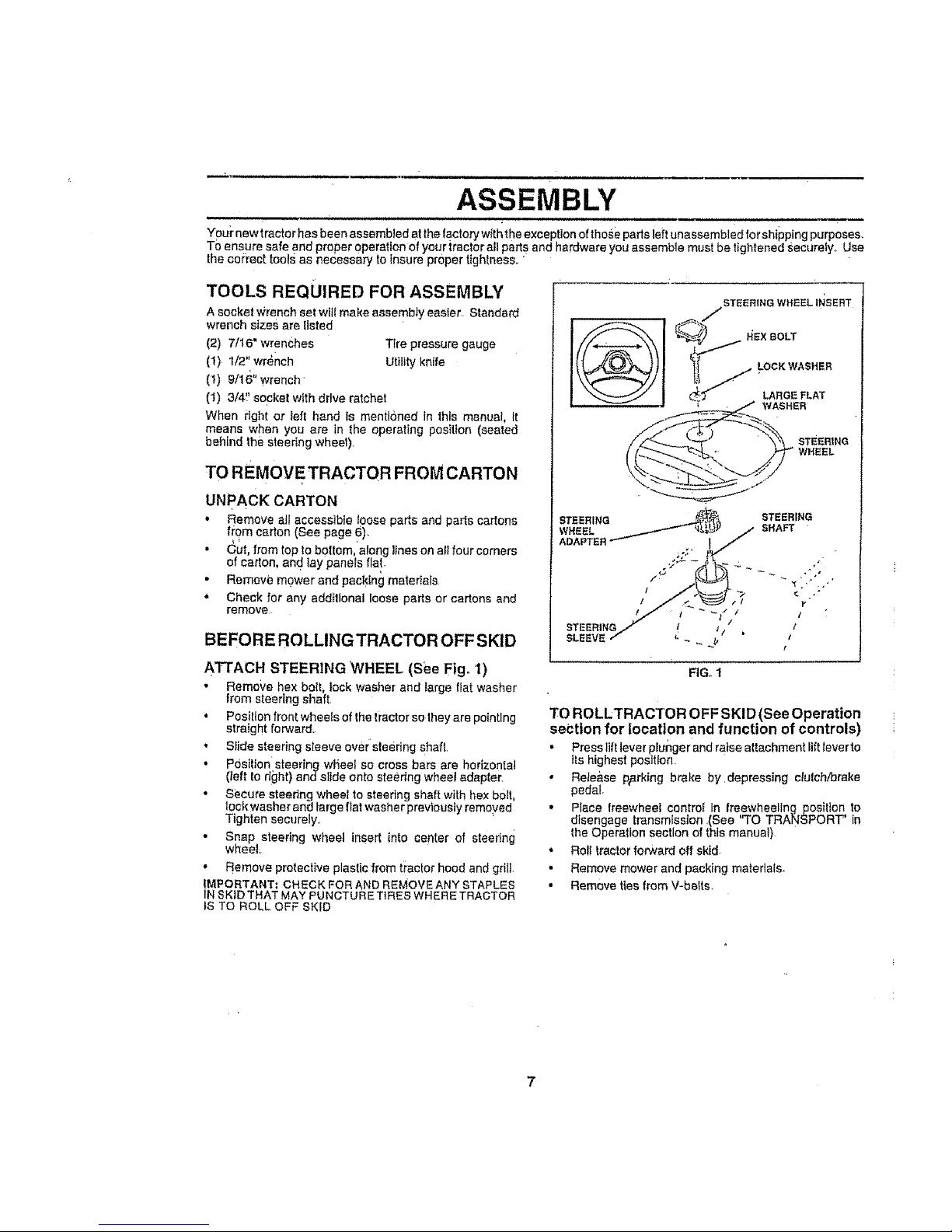
ATTACH STEERING WHEEL (See Fig. 'I)
• Remove hex bolt, lock washer and large fiat washer
from steering shaft
, PosiIIon front wheels of the tractor so they are pointing
straight forward.
,, Slide steering sleeve over sfeedng shaft.
• Posilion sl;eerfng whee! so cross bars are horizontal
(_eft to right) andsiide onto steertng wheel adapter
• Secure steering wheel to steering shaft with hex boil,
lock washer and large fiat washer previously removed
Tighten securely..
• Snap steering wheat insert into center of steeffng
wheel
• Remove protective plastic from tractor hood and grill
IMPORTANT; CHECK FOR AND REMOVE ANY STAPLES
IN SKID THAT MAY PU NCTUR ETIRES WHERE TRACTOR
tS TO ROLL OFF SKID
FIG. 1
TO ROLLTRACTOR OFF SKID (See Operation
section for location and function of controls)
• Press lift tever ptunger and ratse altachment ltfHever to
Its highest position
,' Rete&se p_.rking bt'ake by.depressing clutch/brake
pedal
,, Place freewheel control In freewheeling posilten to
disengage transmission .(See "TO TRANSPORT" In
the Operation section of this manuat)
• Roll tractor forward off skid
. Remove mower and packing materials
• Remove ties from V-belts

ASSEMBLY
;ONNECT BATTERY (See Fig,2)
iii ,nuHu nm ,m,U,l
CAU_rlON: Do not short battery termi-
nals., Before connecting battery, re-
move metal bracelets, wristwatch
bands, rings, etco
Positive terminal must be Connected
first to prevent sparking from acciden-
tal grounding.
i _ 11 1..1 , J,,,,
• Lilt hood to raised position
• Open terminar access doors, remove terminal protec-
• tire caps and discard..
If this battery is put into service alter month and year
indicated on label (iabel located between terminals)
charge battery for minimum of one hour at 6=10 amps.
• First connect RED battery cable to posi{ive (+) battery
terminal with hex bolt, fiat washer, lock washer and hex
nut as shown, Tighten'secUre{y
• Connect BLACK grounding cable to negative (-) bat-
tery terminal with remaining hex boEt,flat washer, lock
washer and hex nut. Tighlen securely
• Close terminal access doors
Use terminal access doors for:
• _hspectton for secure conneclions (to tighten hard-
ware),
• inspec(ion for cbr_osion
• Tesling battery
• Jumping (if required)
Periodic charging
DISCARD HEX NUT LOCK FLAT
WASHER WASHER
TERMINAL
PROTECTIVE HEX
CAPS BOLT
TERMINAL :"
ACCESS
DOOR ,-"
°':_ .
POSITIVE
(RED)
CABLE
NEGATIVE
(BLACK)
CAeLE "
INSTALL SEAT (See Fig. 3)
Adjust seat before tightening adjustment knob,
• Remove cardboard packing on seat pan.
• Place seat on seat pan and assemble shoulder bdtt.,
• • Assemble adjustment knob and flat washer _oosely.-
DO not tighten,,
• Tighten shoulder bolt securely
,, Lower seat inlo operating position and sl! on seat
• Slide seat untila comfodable position is reached which
allows you to press clutch/brake pedal all the way
down
• Get off seat wilhout moving its adjusted positton.
• Raise seat and tighten adjustmenl knob securely,
. SEAT
W.SnER
ADJUSTMENT
KNOB
FIG'. 3
CHECK TIRE PRESSURE
The fires on your tractor were overinflated at the faclory for
shipping purposes. Correct tire pressure is important for
best culting performance.
,. Reduce tire pressure to PSi shown in "PRODUCT
SPECIFICATIONS on page 3 of this manual
CHECK BRAKE SYSTEM
After you learn how to operate your tractor, check to see
that the brake is prqperty adjusted See "TO ADJUST
BRAKE" !n the Service and Adiustments seclion of this
manual
'FIG. 2
8

ASSEMBLY
INSTALl. MOWER AND DRIVE BELT
(See Figs, 4 and 7)
Be sui'a tractor ts on leve! surface and mower suspension
al'ms are raised with attachment llft control. Engage park-
ing brake.
,, Cut and remove ties securing anti-sway bar and belts
Swing sntFsway bar to Jeffside of mower deck_
" Stlde mower under tractor with discharge guard toright
side of tractor,
iMPORTANT; CHECK BELT FOR PROPER ROUTING iN
ALL MOWER PULLEY GROOVES, INSTALL BELT1NTO
ELECTRIC CLUTCH PULLEY GROOVE
h
• lnstatl one front link in top hole of the LH, front mower
bracket and L H front susper_ston bracket. Retain with
two singte loop retainer spdngs as shown
• InstallsecondfronttinkinR.H frontsuspensionbracket
only and retain with singte loop retainer spring as
shown.
" Stide right side of mower back and Install linkin top hole
of R,H, front mower bracket Relain with single loop
retainer spring as shown.,
Turn height adjusfment knob c:ountercfockwise unt[t it
stops.
• Lower mower ltr_kage with attachment lift control,
• Place the suspension arms on inward pointtng deck
pins, If necessary rock and raise front of mower to
alton deck pins with the holes in suspension arms.
SHOULDER
CHASSIS
DOUBLELOOP
RETAINER
ANTI-SWAY
Retain wllh double loop retainer springs with ioops
down as shown
• Connect anti-sway bar to chasss bracket under left
footrest and retain with double loop relainer spring
• Turn height adjustment knob clockwise to remove
slack from mower suspension
° Raise deck to highest pos!tion_
• Assemble gauge wheel bars to brackets using clevis
pihs and doubie toop retainer springs,
, Assemble gaugewhee[s asshown us_nglongshoutder
bolts, 3/8 washers, and 3/8-16 canto rlOcknuts. Tighten
securely.
• Adjust gauge wheels before operating mower as shown
in the Operalton section of this manual,
CHECK MOWER LEVELNESS
For best cutting results mower shouldbe properly eveled
See."TO LEVEL MOWER HOUSING in the Serv ce and
Adjustments section oI this mantJal
CHECK' FOR PROPER POSITION OF ALL
BELTS
See the ftgures Ihat are shown for replacing motion, mower
drive, and mower blade drive beets In the Service and
Adjustments section of thts manuaL Verify that the belts are
routed correctly
FRONT
FRONT
LINKS BRACKETS
L,H. GAUGE
GAUGE
WHEEL
3_
WASHER
USE PLIERS FOR
RETAINER SPRINGS
31S-16
CENTER
LOCKNUT
SINGLE
LOOP RETAINER
SPRINGS
MOWER
BRACKET
DISCHARGE
GUARD
PULLEY
LOOP
RETAINER
SPRINGS
FIG_4
9
i_,,,,u,i, i i , i,i
,/CHECKLIST
BEFORE YOU OPERATE AND ENJOY YOUR NEW
TRA CTOR, WE WISH TO ASSURE THAT YOU RECEtVE
THE BEST PERFORMANCE AND SA TISFA C TION FROM
THIS QUALITY PRODUCT
PLEASE REVIEW THE FOLLOWING CHECKLIST:
,/ All assembly instructions have been completed
.,,z No remaining loose parts in carton.
,/ Battery Is properly prepared and charged. (Minimum .
1 hour at 6 crops)
,/ Seat is adjusted comfortably and tightened securely
,/ AI{ tires ere properly lnflated_ (For shipping purposes,
the tires were overmflated at the factory).
v" Be sure mower deck _spz:operty leveled s_de4o-sidei
front4o-rear for best cutting rest._tts° (Tires must be
properly infla!ed for leveling)..
J Check mower and drive belts, Be sure they are routed
properly around pulleys and inside all bell keepers,
,/ Check wiring See thai all connections are still secure
and wires are properly clamped
,/ Before driving tractor, be sure freewhee! control is in
drive position
WHILE LEARNING HOWTO USE YOUR TRACTOR, PAY
EXTRA A TTENTtON TO THE FOLLOWING IMPORTANT
ITEMS:
v" Engine oil ts at proper level.
v' Fuel tank is filled With fresh, clean, regular unleaded
gasoline
•/ Become familiar with all controls - their location and
function. Operate them before you start the engine
,/ Be sure brake system is tn safe operating cond[tIen
,/ It is important to purge the transmission before operat-:
ing ydur tractor Ior the first time. Foflow proper starting
and transmission purging )nstnlcltons (See '%0 START
ENGINE" and "PURGE.TRANSMISSION" in the Op_-
eration section of this man'Jal).,
" i i ii ,i,,nnlnlnl,i ,I lu,,i III I , _ t • ,
ASSEMBLY
n i ,, i , i , ,
10
OPERATION
m
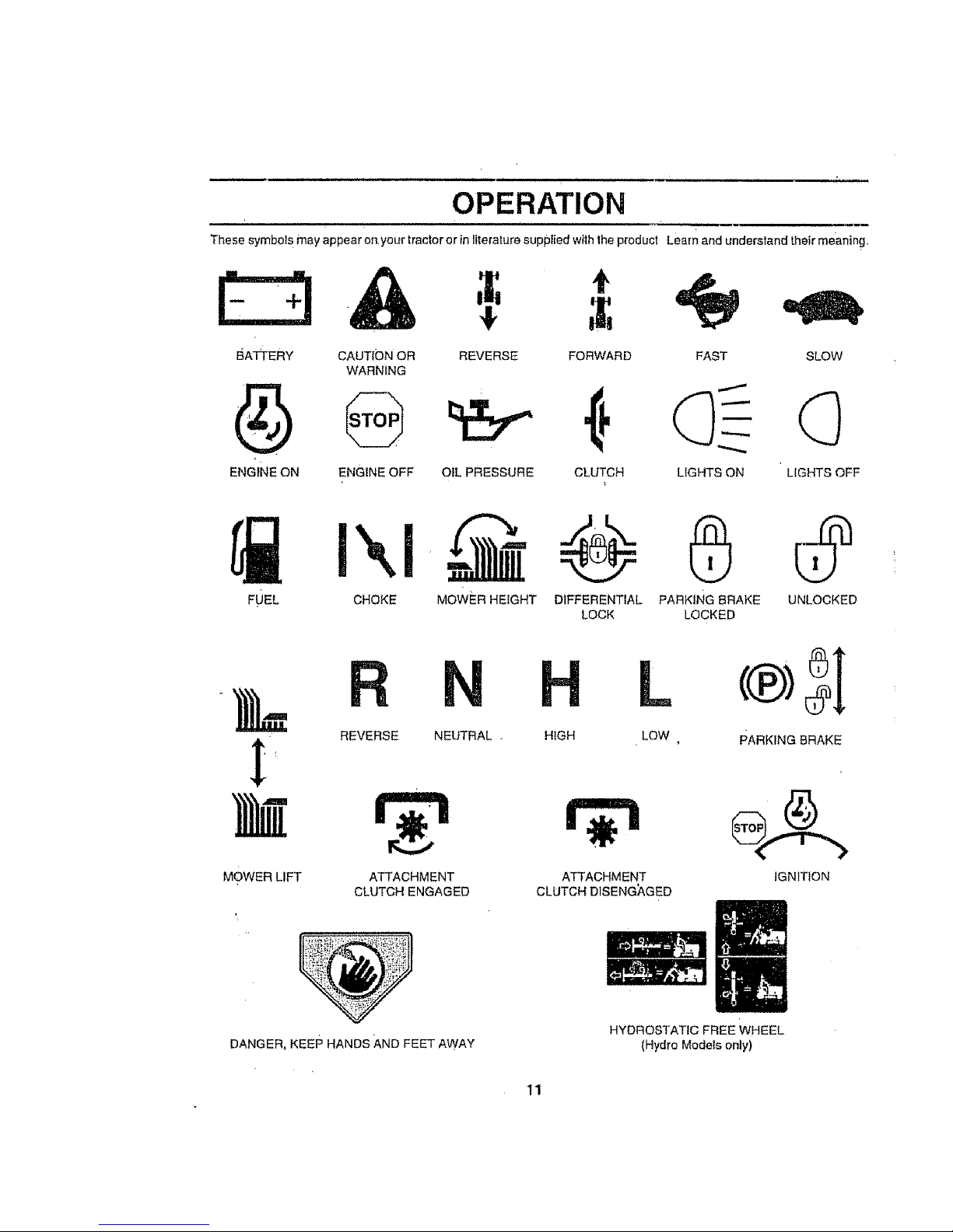
These symbols may appear on.your tractor or in literature suppFied with Ihe product Learn and understand their meaning..
E:3&
BATTEFIY CAUTfON OR
WARNING
@
ENGINE OFF
4!,
t
REVERSE FORWARD SLOW
ENGINE ON OIL PRESSURE CLUTCH LIGHTS OFF
FAST
LIGHTS ON
FUEL CHOKE
MOWER HEIGHT DIFFERENTIAL PARKING BRAKE UNLOCKED
LOCK LOCKED
REVERSE NEUTRAL.
MOWER LIFT
ATTACHMENT
CLUTCH ENGAGED
L
HIGH LOW
ATTACHMENT
CLUTCH DISENG_GED
®SI
PARKING BRAKE
_':'_r,_,_ ' i-'_ _:
DANGER, KEEP HANDS AND FEET AWAY
HYDROSTATIC FREE WHEEL
(Hydro Models only)
OPERATION
• • ...... ,,,,,,, ,,,,,i, , ,, , ,,,,,,,,,,,,,,_, i, ,
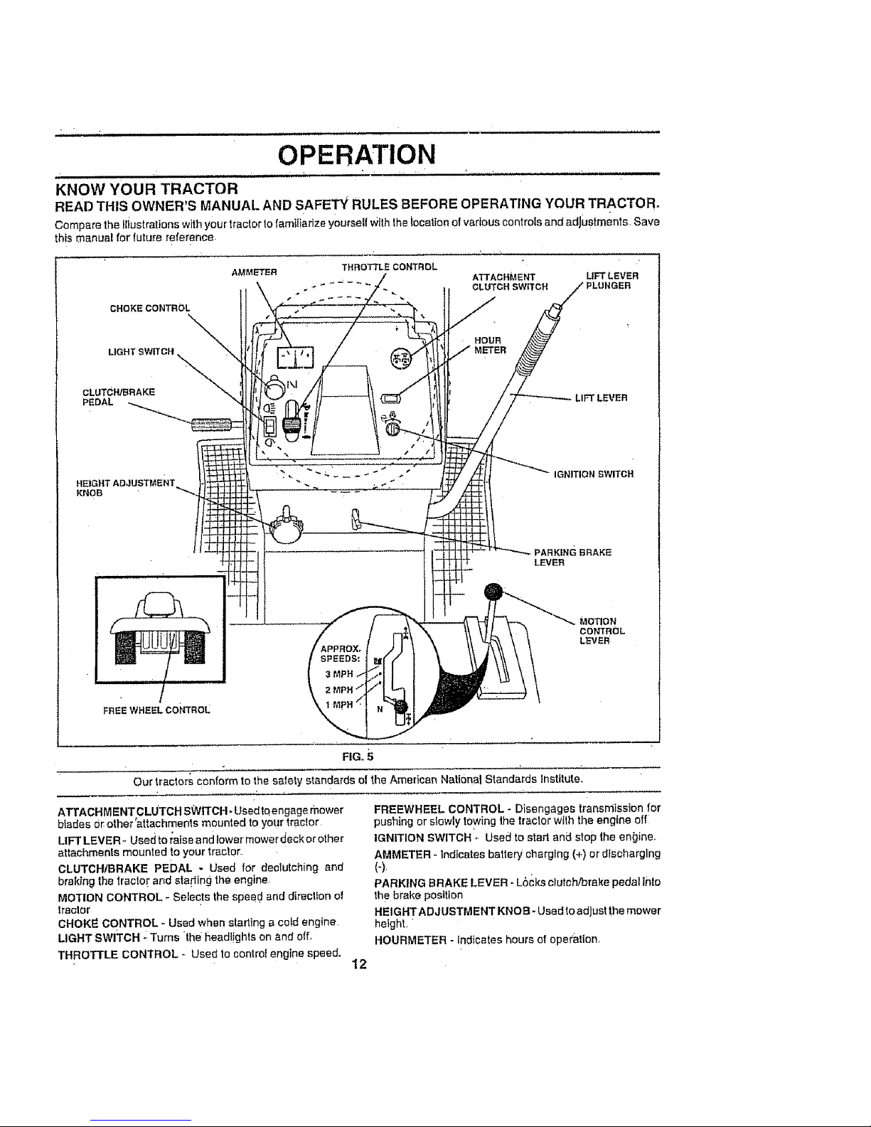
KNOW YOUR TRACTOR
READ THIS OWNER'S MANUAL AND SAFETY RULES BEFORE OPERATING YOUR TRACTOR,
Compare the I{iustrations with your tractor to familiarize yourseif Withthe focalion of various controls and adjustments. Save
this manual for future reference
CROKECONTROL
CLUTCH/BRAKE
PEDAL
HEIGHTADJUSTMENT
KNOB
AMME'TSR
THROTTLE COHTRDL
ATTACHMENT UFTLEVER
. ÷ " " .... CLUTCH SWITCH PLUNGER
HOUR
METER
LIFT LEVER
IGNITION SWITCH
PARKING BRAKE
LEVER
MOTION
CONTROL
LEVER
FREE WHEEL CON"i'ROL
FIG,, 5
Our tractors conform to the salary standards of
ATTACHMENTCLUTCH SWITCH, Usedto engage mower
btades Orether'attachments mounted to your tractor
LIFT LEVER- Used to raise and tower mower deck or other
attachments mounted to your tractor.
Ct.UTCHtBRAKE PEDAL - Used for dectutching and
braking the lractor and sta ding the engine
MOTION CONTROL - Selects the speed and direction of
tractor
CHOKE CONTROL - Used when starting a cold engine,
LIGHT SWITCH - Turns the headt!ghls on _nd off_
THROTTLE cONTROL - Used to controt engine speed.
12
the American National Standards institute°
FREEWHEEL CONTROL * Disengages transmission for
pushing or stowly towing the tractor with the engine off
IGNITION SWITCH - Used to start and stop the en_jine_
AMMETER - indicates battery charging (+) or dfscharglng
(-),
PARKING BRAKE LEVER - Locks c)utch/brake pedal Into
the brake position
HEIGHTADJUSTMENT KNOB - Used to adjust the mower
heighL •
HOURMETER - indicates hours of ope_'atlon_

i i
HOW TO USE YOUR TRACTOR
OPERATION
.u, i iii iiiii ,11,,,11iiiii ii i
The operation of any tractor can result in foreign objects thrown into the eyes, which can resu t l
in severe eye damage. Always wear Safety glasses or aye shields while operating your tractor
f
or performing any adjustments or repairs. We recommend a wide vision safety mask over the
spectacles or standard safety glasses,
.,,HHH
TO SET PARKING BRAKE (See Fig. 6)
Your tracfor isequipped with an opera!or presence sensing
switch. When engine is running, any atlempt by the
operator to leave the seat Without first setting the parking
brake Will shut off the engine.
• Depress clutch/brake pedat into full "BRAKE" position
and hotd
• Place parking brake tever In"ENGAGED" position and
releasepressurefromc}utch/brakepedal Pedalshould
remain in "BRAKE" posi!tOnoMak_ sure parking brake
wiil hold tract6r secure
PUSHiN TO ATTACHMENTCt.UTCH
THROTTLE "DISENGAGE" SWITCHPULLOUTTO
NOTE: Undercedaln conditions when unJtis standing idle
with the engine running, hot engine exhaust gases may
cause "browning" of grass To eliminate this possibility,
always stop engine when stopping tractor on grass areas
'_ CAUTION: Always stop tractor corn:
pletely, a s described above, before leav-
ing the operator's position; to empty
grass catcher, etc..
TO USE CHOKE CONTROL (See Fig. 6)
Use choke €ontrol whenever you are stading a coldengine.
Do not use to slart a warm engine
• To engage choke conlroL pull knob out. Slowly push
knob in to disengage
CONTROL LEVER _,---=--,_. "ENGAGE'_
##
o.o,o,o2%,
PEDAL"BRAKE" \ \ _ i _'_ \\-_'-'_ ./
_-_ I / _'-_. \ CONTROL
t .EI . " "X
POSITION KNOB BRAKE
"DIS ENGAGJSD'" "ENGAGED"
POSITION. POSFION
FIG: 6
STOPPING (See Fig, 6)
MOWER BLADES o
TO USE THROTTLE CONTROL (See Fig. 6}
Always operate engin_ at ful] throttle
• Operallng engine at tess than full throttle reduces the
baltery charging rate
• Full Ihrattle offers the best baggirlg and mower perfor-
mance
TO MOVE FORWARD AND BACKWARD
(See Fig, 6)
The direction and speed o_movement is controlled by lhe
motion control lever
• Start tractor wilh motion Controllever in neutral (N)
position
• Release parking brake and clutch/brake peda!.
• Slowly move molion control lever todesired position,
TO ADJUST MOWER CUTTING HEIGHT
(See Fig_ 6)
Thecuttingheight iscontrolled byturninglhe heightadiusl-
ment knob in desired direction
• Turn knob clockwise ((-_1)to raise cutting height,
• Move attachment clutch switch to "DISENGAGED"
posilton
GROUND DRIVE -
• Depress clutch/brake pedal into lull "BRAKE" position.
• Move motion control lever to neutral (N) poe!lion
IMPORTANT: THE MOTION CONTROL LEVER DOES
NOT..RETURN TO NEUTRAL (N) POSIT!ON WHEN THE
CLUTCHtBRAKE PEDAL IS DEPRESSED
ENGINE -
• Move throttle control tO slow (.,=_) position.
NOTE: Failure to move throttle control to stow (,,a_)
position and allowing engine to idle before stopping may
cause engine to "backfire"
• Turn ignition l<ey to "OFF" position and remove key.
Always remove key when leaving tractor to prevent
unalJthorlzed use.
• Never use choke tO slop engine..
• Turn knob counterclockwise ()¢%} to lower'cutilng
height
The culling height range is approximately 1-1/4" Io 4-1/2"
The heights are measured from the ground to the blade tip
with the engine not running These heights are approxi;
mate and may vary depending upon soil csndittohs, height
_?lgrass and types of grass being mowed.
• The average lawn should be cut toapproximately 2-I12
inches during the cool season and to over 3 inches
during hot months For healthier and better looking
lawns, mow often and after moderate growth°
, For best culling performance, grass over 6 inches in
heighl should be mowed Iwice Make the flrsl cut
relatively high; !he second to desired height
13
OPERATION
,, ,, ,,,,,,,,,,,, i,,,11,
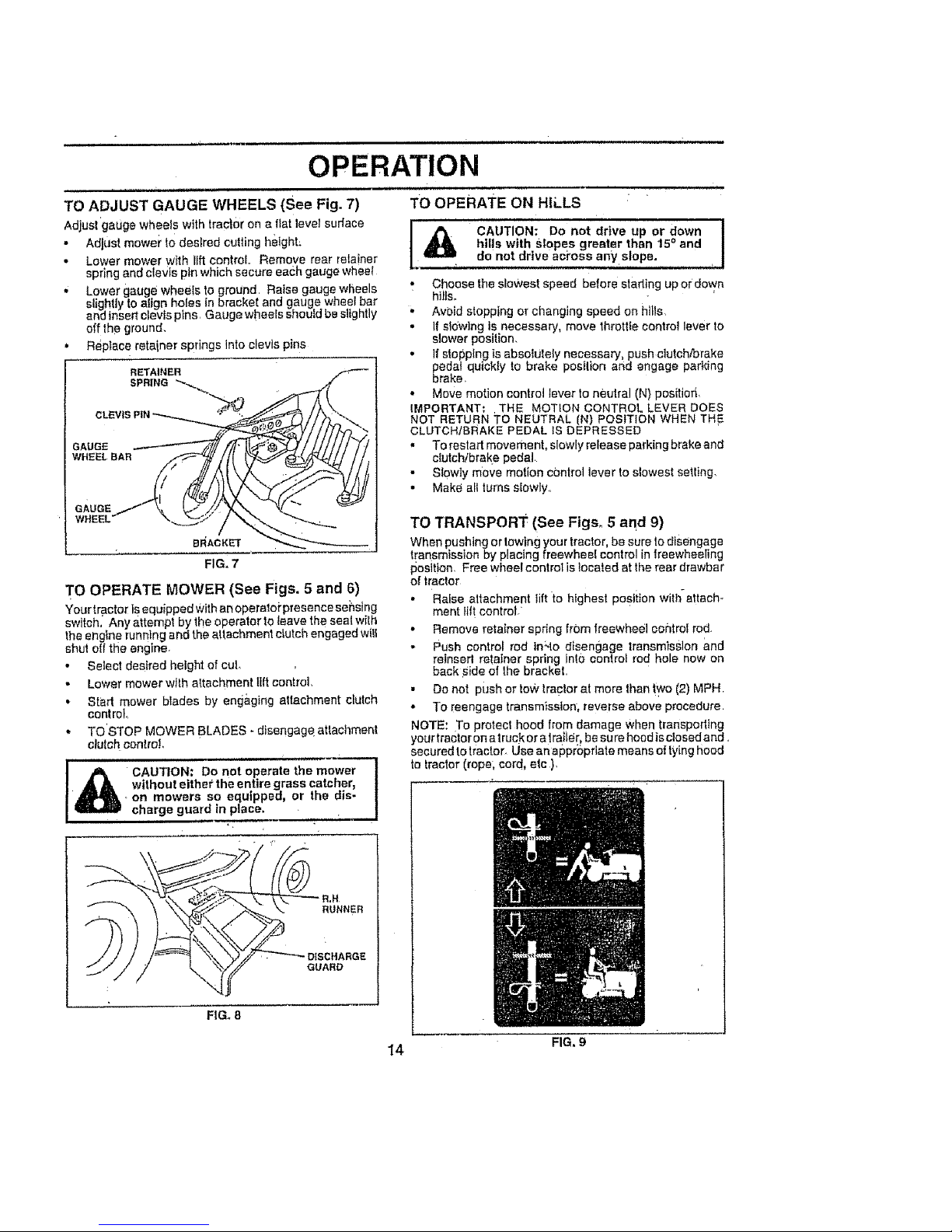
TO ADJUST GAUGE WHEELS (See Fig. 7)
Adjust gauge wheels with trac|or on a flat level suriace
• Adjust mower to desired cutting height:
• Lower mower w_th lift control Remove rear relainer
spring and clevts pin which secure eac:h gauge wheet
. Lower gauge wheels to ground Raise gauge wheels
slightly to align holes in bracket and gauge wheel bar
and insert clevis pins Gauge wheels should be slightly
off the ground_
• Repiace retainer springs lnto clevis pins
RETAINER
SPRING _,_
GAUGE
WHEEL BAR
GAUGE
WHEEL
FIG. 7
TO OPERATE MOWER (See Figs. 5 and 6)
Your tractor is equipped With an operaloi'presence sensing
sw teh. Any attempt by the operator to leave the seal wilh
the engine running and the attachment cLutc _engaged w II
shut elf the engine,
• Select desired height of cuL
• Lower mower with altachment lift control,
• Start mower blades by eng&ging altachment clutch
control
,. TO STOP MOWER BLADES - disengageaftachment
clutch control,
l _ CAUTION: Do'not operate the m_wer_
without either the entire grass catcher, !
. on mowers so equipped, or the dis- !
charge guard in place. . . I
. m _ m " =J
RUNNER
GUARD
FIGo 8
TO OPERATE ON HILLS
I CAUTION: Do not drive up or down !
hills with SlOpes greater than 15 ° and
I
do not drive aci'oss any slope. •
,_ Choose the slowest speed before stading up or down
hi_ls°
• Avoid stopping or changing speed on httls,
• if sldw]ng is necessary, move throttle control lever to
slower position.
• If stopping is absolutely necessary, push clutch/brake
pedal quickly to brake posilion and engage parking
brake
• Move motion control lever to neutral (N) pos_tiorl,
IMPORTANT: THE MOTION CONTROL LEVER DOES
NOT RETURN TO NEUTRAL IN) POSITION WHEN TH 5
CLUTCHtBRAKE PEDAL iS DEPRESSED
" To restart movement, slowly release parking brake and
clutch!brake pedal
• Slewty m0ve motion control lever to slowest setting.
• Make all turns slowly
TO TRANSPORT (See Figs, 5 and 9)
When pushing or lowing your tractor, be sure 1o disengage
t[ar_smisslon by placing freewhee! control in treewheeling
posltion_ Free wheel conlrot is tocaled at the rear drawbar
of traclor
• Raise altachment tilt to highest PoStiion with-attach-
ment lift control/
• Remove retainer spring from freewheel cohlroI rod.
• Push control rod tn'.to disengage transmission and
retnsert retainer spring inl0 control rod hole now on
back Side of lhe bracket
• Do not push or low tractor at more than ly¢o (2) MPH
• To reengage transmission, reverse above procedure
NOTE: To protect hood from damage when transpodtng
your tractor on a truck or atra_ie[_be su re hocd is clese dand.
secured to tractor_ Use an eppropriate means of tying hood
to lractor (rope; cord, etc ),
14 FIG, g
OPERATION
BEFORE STARTING THE ENGINE
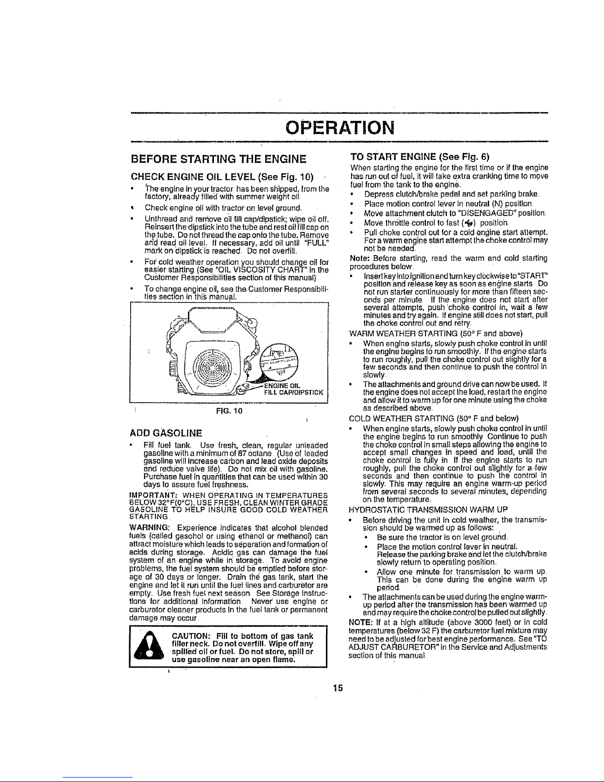
CHECK ENGINE OIL LEVEL (See Fig, 10)
• The engine tn your tractor has been shipped, from the
factory, already filled with summer weight oil
Check engine oil with tractor on level ground,
• Unlhread and remove oit fill cap/dipstick; wipe oil off,
Reinsert the dlpslick Into the tube and rest oii fill cap on
the tube. De not thread the cap onto the tube. Remove
arid read oil level, it necessary, add oi! until "FULL"
mark on _Ipstick ISreached, Do not overfitL
, Fo='cold weather operation you shoutd change oil for
easier stait}ng (See "OiL VISCOSITY CHART" tn the
Customer Responsibilities section of this manual)
• To change engine oil, see the.Customer Responsibili-
ties section in this manual.
i
FILLCAP/DIPSTICK
FIG. 10
ADD GASOLINE
• Filt fuel tank, Use fresh, clean, regular unleaded
gasoline with a minimum of 87 octane (Use Of leaded
gasoline will increase'carbon and lead oxide deposits
afld reduce valve life), Do nol mix oil with gasoline,
Purchase fuel In quar_ttttes that can be Used within 30
days to assure fuel f(eshnesso
IMPORTANT; WHEN OPERATING IN TEMPERATURES
BELOW 32"F(0°C), USE FRESH. CLEAN WINTER GRADE
GASOLINE TO HELP INSURE GOOD COLD WEATHER
STARTING
WARNING: Experience indicates that alcohof blended
fuels (called gasohot or using ethanol or methanol) can
attract moisture which Ieads to se_paralien and formation of
acids during storage. Acidic gas Can damage the fuel
system of an engine while tn storage To avoid engine
problems, the fuel system should be emptied before stor-
age of 30 days or longer. Drain the gas tank, start Ihe
engine and let tt run until the fuel lines and carburetor are
empty_ Use fresh rue! next season See Storage instruc-
tions for additional Ir}format_on Never use engine or
carburetor cleaner products In the fueJ tank or permanent
damage may occur
CAUTION: FIll to bottom of gas tank-_l
filler neck. Do not overfilL Wipeoffany I
spilledo orfueL Do not store, splllor I
use gasoline near an open flame. /
TO START ENGINE (See Fig. 6)
When starting the engine for the firs_ time or if Ihe engine
has run out of fuel, II wiil take extra cranking time to move
fuel from the tank to the engine
• Depress clutch/brake pedal and set parking brake,
• Place motion control lever tn neutral (N) position
• Move attachment clutch to "DISENGAGED" position,
• Move Ihr6ttle control to fast (,f_) pos[tloh
• Pull choke control out for a cold engine start attempL
For a warm engine start attempt the choke control may
not be needed,
Note: Before starting, read the warm and cold starting
procedures below
• Insert key Intotgnllionand rum key clockwise to°START"
position and release key as soon as engine alerts Do
not run Starter continuously for more than fifteen sec-
onds per minute If Ihe engine does not alert after
several attempts, push 'choke control In, wait a few
minutes and try again, tf engine still does not start, pull
the choke control out end re|_
WARM WEATHER STARTING (50 ° F and above)
• When engine starts, slowly push choke control in unlt]
the engine begins t0 run smoothly, if ihe engine sfarts
to run roughly, pull Ihe choke control out s}ightly for a
few seconds and then continue to push the control In
slowly
• The altechmeflls and ground drive can now be used. _1
%heengine does not accept the lea& restart the engine
and allow i_to warm up for one m_nute using the choke
as described above,
COLD WEATHER STARTING (50 ° F and below)
• When engine starts, slowty push choke control in unti!
lhe engine begins to run smoothly Continue to push
the choke control in smalt steps at_owing the engine to
accept small changes in speed and toad, until the
choke control Is fully in If the engine starts to run
roughly pull the choke control out s_ightly for a few
seconds and then continue to push the control in
sloWly, This may require an englne warm-up period
from several seconds to severe! minutes, depending
on the temperature,
HYDROSTATIC TRANSMISSION WARM UP
- Before driving the unit in cold wealher, the transmis-
slon should be warmed up as foIIows:
• Be sure the tractor Is on level ground,
• Place the motion control lever in neutral,
Release the parking brake and let the clutch/brake
slowly return to operating posi!ion.
• Allow one minute for transmission to warm up,
This can be done during the engine warm up
pedod.
• The attachments can be used during the engine warm-
up period after the transmission has been warmed up
and may requlrethe choke control be puffed out siighIly
NOTE: if at a high altitude (above 3000 feet) or in cold
temperatures (below 32 F) the carburetor rue! mixture may
need to be adjusted for best engine performance, See 'rTO
ADJUST CARBURETOR" in the service and Adjustments
section of this mant_al
15
uiH illll
OPERATION
PURGE TRANSMISSION
CAUTION; Neverengageordisengage
freewheel lever while the engine isrun-
ning_
To ensure proper operation and performance, it is recom-
mended thai the transmission be purged before operating
tractor for the first time. This procedure wi!t remove any
trapped air inside the transmission which may have devel-
oped dudng shipping of your traclor
IMPORTANT; SHOULD YOLtR TRANSMiSSiON REQUIRE
REMOVAL FOR SERVICE OR REPLACEMENT, tT
SHOULD BE PURGED AFTER REINSTALLATtON
BEFORE OPERATING THE TRACTOR
• Piace tractorsafety on level surface with engine off and
parking brake set
Disengage tran'smtsslon by placing freewheel control
[n freewheeling position (See "TO TRANSPORT" in
this sectbr_ of manual)
- SIttingtnthetractorseat,stadengine Afterfheengine
ts running, move throttle control to stow (.gh) position
W th Got on control lever inneutral (N) position, slowty
disengage clutch/brake _0edal
• Move motion control lever to full forward position and
hold for five (5} seconds. Move Iever to full reverse
position and hold lot five (5) seconds° Repeat this
• procedure three (3) times,
NOTE; During th_sprocedure ther_ wilI be no movement of
drive wheels. The air is being removed from hydratJtlc drive
system.
• Move motion controileverto neulral (N) position. ShuF
off engine and set parking brake-
. Engage transmission by placing freewheel control in
driving position (See "TO TRANSPORT" inthis section
o4manua!).
• Sitting tn the tractor seat, start engine. After the engine
is.running move lhrottte control to half (1t2) speed.
With metbn control lever tnneutral (N) pos I on, s ow y
disengage clutch/brake pedal
• Slowly move motion control lever forward, alter the
tractor moves approximately live (5) feet, sIewly move
motion control lever to reverse posltton. After the
tractor moves approximately five(5)feet return the
motion control lever to the neutral (N) position. Repeat
this procedure with the moti0fl conlrol lever three (3)
times_
• Your tractor is now purged and now ready for normal
operation.
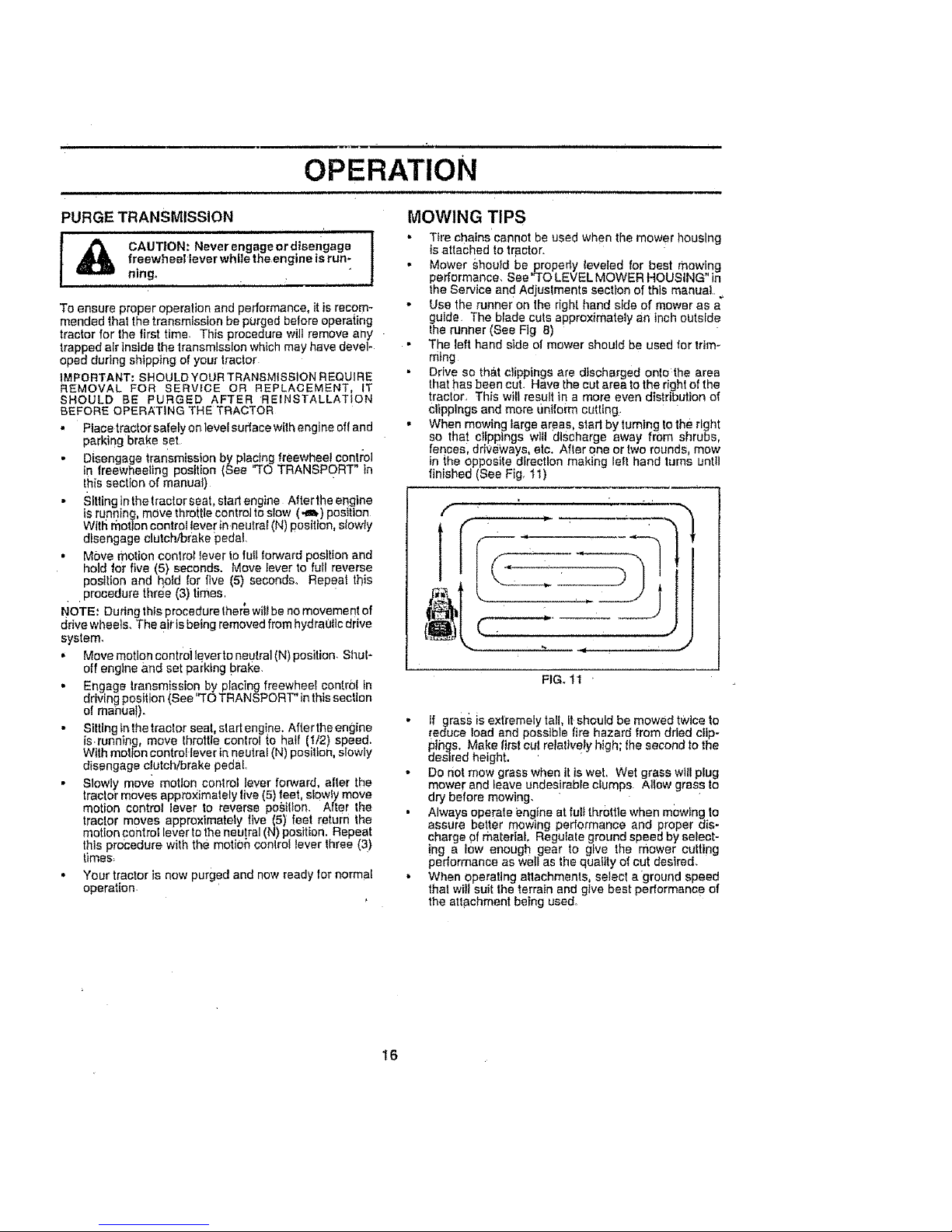
MOWING TIPS
• Tire chains cannot be used when the mower housing
isattached to tractor.
• Mower should be propedy leveled for best mowing
performance. Sea'TO LEVEL MOWER HOUSING" in
the Service and Adjuslments section of this manual.
• Use the runner on the right hand side of mower as a
guide The blade cuts approximately an inch outside
the runner (See Fig 8)
• The left hand side el mower should be used for trim-
ming
• Drive so tha.t clippings are discharged onto the area
that has been cut. Have the cut area to the right of the
traclor. This will result in a more even distribution of
Clippings and more _intfoim cutting.
• When mowing Iarge areas, starl by turning to the right
so that cFIpptngs will discharge away from shrubs,
fences, driveways, etc. After one ortwo rounds mow
in _,heopposile direction making left hand turns until
finished (See Fig. tl)
[;
f
FIG. 11 '
• ff grass is extremely tall, it should be mowed twice to
[educe Ioad and possible fire hazard from dried cllp-
pings. Make first cu_ relatively high; the second to the
desired height.
• Do not mow grass when tt is wet, Wet grass will plug
mower and leave undes!rable clumps AIIow grass to
dry before mowing,
• Always operate engine at ful_throttle when mowing to
assure better mowing performance and proper dis-
charge f_f material, Regulate ground speed by seFect-
!ng a low enough gear to give the mower culling
performance as well as the quaitty of cut desired.
• When operating attachments, select a ground speed
thai will suit the terrain and give best performance of
the att#chment being used.
16
, ,,, .,,...Hi, ,
CUSTOMER RESPONSIBILITIES
,,u,, Jl ,,,,, ,1111, ,,,, , m .........J,u,,,,,,,,,,,,,,,,u
......... _ _ ..........._ ......
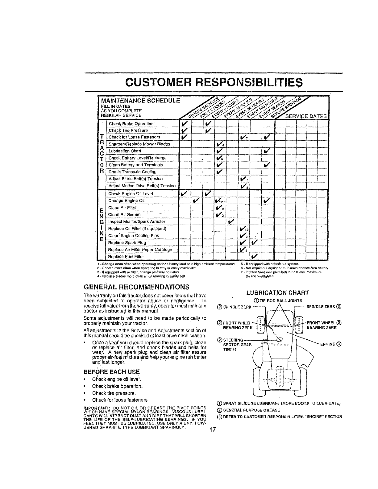
'MAINTENANCE SCHEDULE _.,_ ._,_/_'_,,_, o_'_,_X_' '''"
AS YOU COMPLETE
REGULAR SERVICE ,##-,_o_ _',_7 _'_ _,.._" _'_,.._/_.,-" _.T/" '_,Y'_,,,,'_SERVICE DATES
Check _rB Pressure i tf t,/
i T Check lo_ LOOSe Fasteners If ......1 #m##_' if - --
c Sho eo,Ra,lo oMow ,;,,'0,ee,""';;;;;..... V', -- .__Lubrication Chart ! If
T Check earlap/LeveIIRechsrge
0 Ctean_a_ta_aedTe_._a!e ---_ _ iV' V"
a Check Tr_nsa×le c6oting if
Adjust Blade Bell(e} Tension V"s ,,
Ad_,etMe,.:.T....,vo._.a,(e)._.no Tenancy, v', : ......
Ch_o_E_g!_,ao,Lena,............_ _ I { "
,,Change Englne OI! ...... . • , I #/ t_.z.= { lt_
E CIean Air Filler V_
N C!a_,n,AIrScreen,, I V'= .........
G Inspect Mu{fler/gpark Arresler J 1_ ......
Replece 011 FHIer (Ifequipped) I."_,_
Replace Spark Plug V _ If
Replace Air Fi_ler Paper Cartridge ...... _ __ _ .... _
R_p_aeaFuel_I!!,£.................. V'
1 ..Ch_,ngt_more oft_r_ wM_n 0_e_ling _zl_of t_hn_tv_{o_d .o_I_ high _bi_t _mpe_BlU/_ S - II eq_ipped wilh ad_tlsiabl_* uy_im.
2 Se_lco n_olo o[I_n wt_en Operating I_1ditty ot d_ly ¢o_lt_or_ r 6 _NOI _r_qt_red I1equipped wilh m_l_l_na_ce-hee battery
3 ,,I__qulpp._t't.,l_t_oillille,+change oI_ow_ 50 t_u_ 7 ,.TJEii_I_n(_o_n[it._iepivotb_IIIo35 {I_tbs_Imitm
4 ..RepF_cr_t_lado,_morn ellen wf_en mowh_g in s_nd_ soil Co r_otov_ttlghlen
GENERAL RECOMMENDATIONS
Thewarrantyonthlstractordoesnotcoveritemsthathave
been subjected to operator at_use or negIigenee, To
receive fu!lvatue from the warra}ity operator must maintain
tractor as Instructed in this manuat
Some;adjustments willneed to be made periodicallyto
propeily maintain your tractor
All adjustments tn the Service and Adjustments sectlc)n of
this manL_at should be checked at least once each season
• Once a yea€ you should replace the spark plug, clean
or replace air filter, and check blades and bells for
wear, A new spark plug and clean air filter assure
proper air-fueJ mixture ,and help your engine ruh better
andlast longer
BEFORE EACH USE
• C_eek engine oil level°
• Check brake Operation.
• Checktire pressure
• Check for loose fasteners,
IMPORTANT: DO NOT OIL OR GREASE THE PIVOT POINTS
WHICH HAVE SPECIAL NYLON BEARINGS VISCOUS LUBRI-
CANTS WILL ATTRACT BUST AND DIRT THAT WILL SHORTEN
THE L_FE OF THE SELF-LUBRICATING BEARINGS. _F YOU
FEEL THEY MUST BE LUBRICATED, USE ONLY A DRY, POW-
DERED GRAPHITE TYPE LUBEIICANT SPARINGLY
LUBRICATION CHART
(_TtB ROD BALL JOINTS
®
®FRONT _FRONT WHEEL_[)
BEARING ZERK BEARING ZERK
®
SECTOR GEAR ®
TEETH
(_) SPRAY SILICONE LUBRICANT (MOVE SOOTS TO LUBRICATE}
(_ GENERAL PURPOSE GREASE
® REFER TO CUSTOMER REBPONSIBtLITIES "ENGINE" SECTiON
17
CUSTOMER RESPONSIBILITIES
TRACTOR
Always observe safety rules when performing any mainte-
narcs
BRAKE OPERATION
If tractor requires more than six (6) feet stopping distance
a{ high speed fn highest gear, Ihen brake must be adjusted.
(See "TO ADJUST BRAKE" In the Service and Adjust-
ments section of this manual)
TIRES
• Maintain proper airpressure in all tires (See "PROD-
UCT SPECIFICATIONS" on page 3 of this manual):
• Keep tires free ol gasot(ne, oil, or insect control chemi-
cals which can harm rubber,
• Aveid.slumps, slones, deep ruts, sharp objects and
other hazard s that may cause tire damage.
BLADE CARE
For best results mower blades must be kept sharp, Re-
place bent or damaged blades,
BLADE REMOVAL, (See Fig, 12)
• Raise mower to highest position to allow access to
blades, "
• Remove hexboit, lock washer and flat washer securing
blade
• tnstall new or resharpened blade with trailing edge up
towards deck as shown
,, Reassemble hex bolt, tock washer and fiat washer in
exact order as shown
,, Tighten bolt securely (30-35 FI. Lbso torque).
iMPORTANT: BLADE BOLTISGRADEBHEATTREATED
NOTE: We do net recommend sharpening blade -,bul ifyou
do, be su_'ethe blade is balanced,
a.... _ MANDREL
_,_u_ t",__-_.._.*,_ ASSEMBLY
J
REX BOLT (GRADE 81 "--_.' "_
'AGRADE aHEAT TREATED BOLT CAN BE
IDENTIFIEDBY SIXLINESON THE BOLT HEAD.
FIG. 12
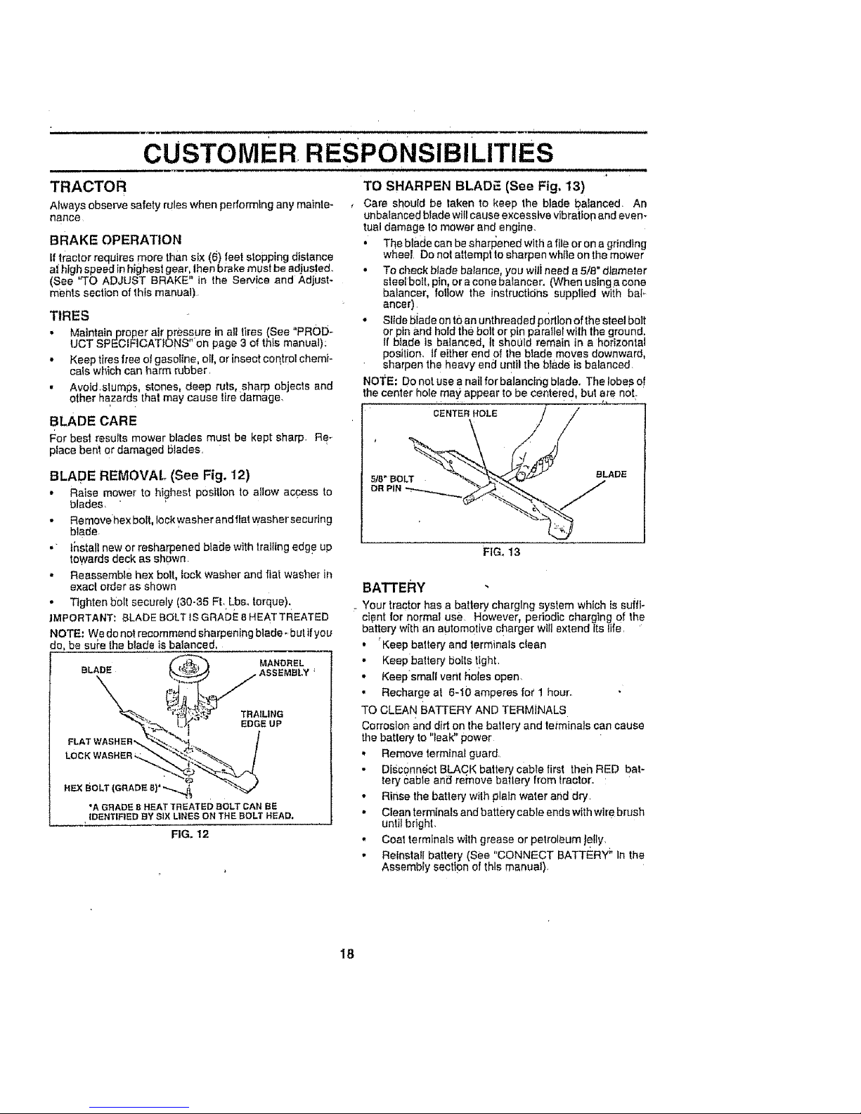
TO SHARPEN BLADF_(See Fig, 13)
, Care should be taken to keep the blade balanced. An
unbaianced btade will cause excessive vibration and even*
tuB! damage to mower and engine.
• The blade can be sharFJened with a file or on a grinding
wheel Do not attempt to sharpen while on the mower
• To check blade balance, you will need a 5/8" diameter
ales{bolt pin, or a cone ba_ancer, (When using a cone
balancer, follow the instructtdhs supplied with bal*
anger)
• Slide biade on to an unthreaded portion of the steel bolt
or pin and hold the bolt or pin parallel wilh the ground.
If btade is balanced, it shoLJld remain in a horizontal
position, tf either end of the biade moves downward,
sharpen the heavy end until the blade is balanced
NOTE; Do not use a nail for balancing blade. The lobes o!
the center hole may appear to be centered, but are not.
NTE"HOLE/ /
FIG, 13
BATTERY
Your tractor has a battery charging system which is suffi-
cient for normal use However, periodic charging of the
battery with an automotive charger will extend Its {ire, '
• "Keep battery and !erminals ctsan
• Keep battery botts t!ght,
• Keepsmall vent tlo_esopen.
• Recharge at 6-!O amperes for I hour,
TO CLEAN BATTERY AND TERMINALS
Corrosion and dirt on the batlery and tei_minalscan cause
the batte_ to "Ieal¢' power
• Remove termina_ guard
Digc0nn6ct BLACK battery cabte first then RED bat-
tery Cable ani_ rei'nove batlery from tractor.
• Rinse the battery with plain water and dry,
• Clean terminals and batterycable ends with wire brush
unlit bright.
• Coat terminals with grease or petroleum Jetly.
• Reinstall battery (See "CONNECT BATTERY _'In the
Assembly section of this manuaI).
18
 Loading...