

Sears Craftsman 390.250097 Owner's Manual
SEARS
OWNER'S
MANUAL
MODELNO.
390.250097
CAUTION:
Read and Follow
All Safety Rulesand
Operating Instructions
Before FirstUse of
ThisProduct.
Save This Manual For
Future Reference.
I:RRFTSMRN°
112 HP SHALLOW WELL
WATER SYSTEM
• Safety Instructions
• Installation
• Electrical
• Maintenance
• Repair Parts
Sears, Roebuck and Co., Hoffman Estates, IL 60179 U.S.A.
PRINTED IN U.S.A. Form NO.F642-9822 (9/25/98)
CONTENTS
INTRODUCTION/WARRANTY ..................................................... 2
PUMP PERFORMANCE .................................................................. 3
MAJOR COMPONENTS ................................................................. 3
INSTALLATION .......................................................................... 4-5
ELECTI_CAL ............................................................................... 5_
OPERATION .................................................................................. 7
MAINTENANCE ........................................................................ 7-10
HELPFUL HINTS .......................................................................... 11
REPAIR PARTS ........................................................................ 12-14
TROUBLESHOOTING GUIDE ..................................................... 15
INTRODUCTION
Please read our instructions before installing and using your
Shallow Well Water System. This will help you obtain the full ben-
ellts of the quality and convenience built into this equipment. It
will also help you avoid any needless service expense resulting
from causes beyond our control which are not covered by our war-
ranty.
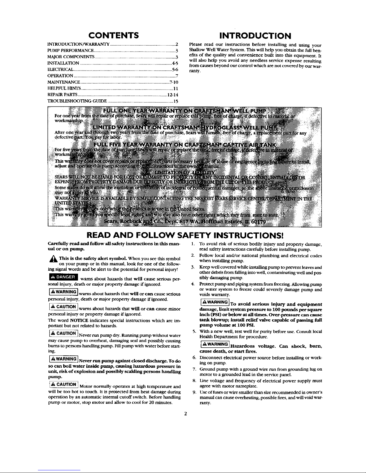
READ AND FOLLOW SAFETY INSTRUCTIONS!
Carefully read and follow all safety instructions in this man-
ual or on pump.
_Thls is the safety alert symboL When you see tins symbol
on your pump or in this manual, look for one of the follow-
ing signal words and be alert to the potential for personal injury!
_ warns about hazards that will cause serious per-
sonal injury, death or major property damage if ignored.
_ warns about hazards that will or can cause serious
personal injury, death or major property damage if ignored.
F
_& CAUTION _warns about hazards that will or can cause minor
personal injury or properly damage if ignored.
The word NOTICE indicates special instructions which are im-
portant but not related to hazards.
_ Never run pump dry. Running pump without water
may cause pump to overheat, damaging seal and possibly causing
burns to persons handling pump. Fill pump with water before start-
ing.
L_'WARNING JNever nm pump against closed discharge. To do
so can boll water h_lde pump, causing hazardous pressure in
unit, risk of explosion and possibly scalding persons handling
pump.
_, CAUTION
[ I Motor normally operates at high temperature and
will be too hot to touch. It is protected from heat damage during
operation by art automatic internal cutoff switch. Before handling
pump or motor, stop motor and allow to cool for 20 minutes.
1. To avoid risk of serious bodily injury and property damage,
read safety instructions carefully before installing pump.
2. Follow local and/or national plumbing and electrical codes
when installing pump.
3. Keep well covered while installing pump to prevent leaves and
other debris from falling into well, contaminating well and pos-
sibly damaging pump.
4. Protect pump and piping system from freezing. Allowing pump
or water system to freeze could severely damage pump and
voids warranty.
L_'WARNING_To avoid serious injury and equipment
damage, limit system pressure to 100 pounds per square
inch (PSI) or below at all times. Over-pressure can cause
tank blowup; install relief valve capable of passing full
pump volume at 100 PSI.
5. With a new well, test well for purity before use. Consult local
Health Department for procedure.
_ q
[&WARNINGJHazardous voltage. Can shock, burn,
cause death, or start fires.
6. Disconnect electrical power source before installing or work-
ing on pump.
7. Ground pump with a ground wire run from grounding lug on
motor to a grounded lead in the service panel.
8. Line voltage and frequency of electrical power supply must
agree with motor nameplate.
9. Use of fuses or wire smaller than size recommended in owner's
manual can cause overheating, possible fires, and will void war-
rarity.
2
Pump
Model
390.250097
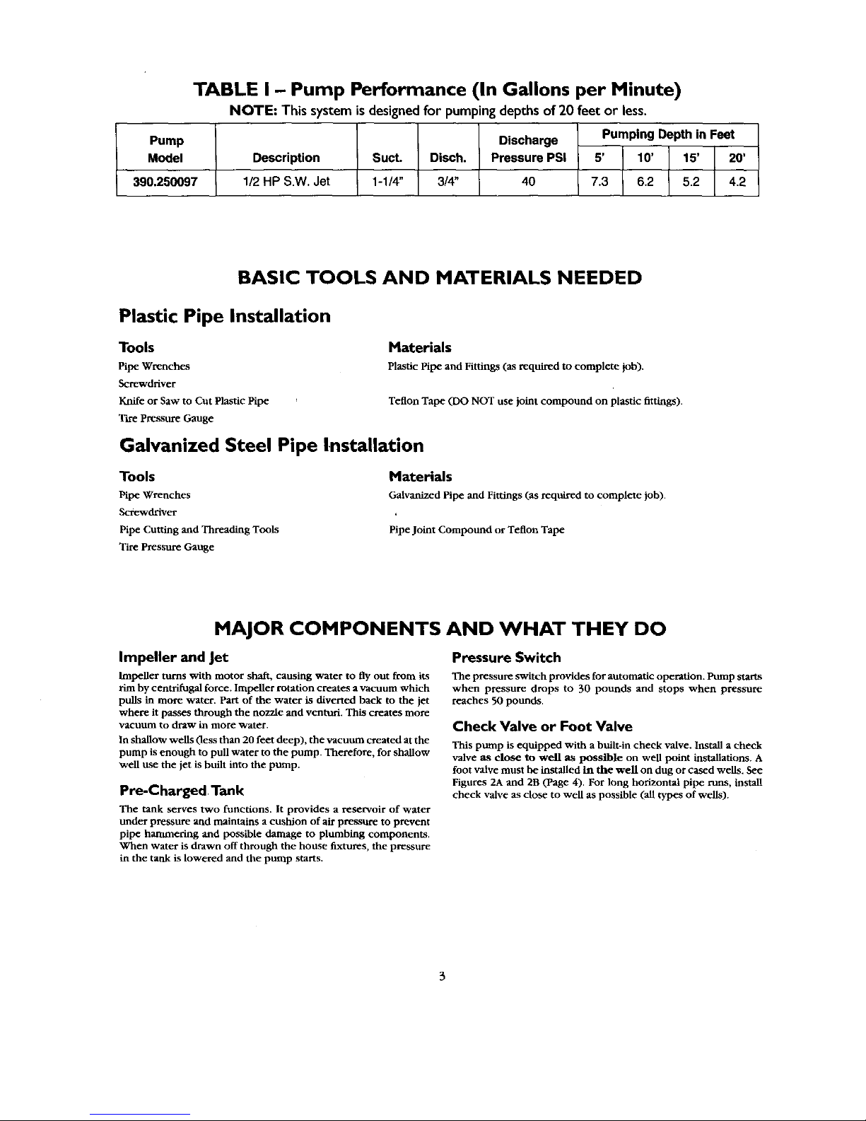
TABLE I - Pump Performance (In Gallons per Minute)
NOTE: This system is designedfor pumping depths of 20 feet or less.
Discharge Pumping Depth in Feet
Description Suct. Disch. Pressure PSi 5' 10' 15' 20'
1/2 HP S.W. Jet 1-1/4" 3/4" 40 7.3 6.2 5.2 4.2
BASIC TOOLS AND MATERIALS NEEDED
Plastic Pipe Installation
Tools
Pipe Wrenches
Screwdriver
Knife or Saw to Cut Plastic Pipe
Tire Pressure Gauge
Materials
Plastic Pipe and Fittings (as required to complete lob).
Teflon Tape (DO NOT use joint compound on plastic fittings).
Galvanized Steel Pipe InstaUation
Tools
Pipe Wrenches
Screwdriver
Pipe Cutting and Threading Tools
Tire Pressure Gauge
Materials
Galvanized Pipe and Fittings (as required to complete job).
Pipe Joint Compound or Teflon Tape
MAJOR COMPONENTS AND WHAT THEY DO
Impeller and Jet
Impeller turns with motor shaft, causing water to fly out from its
rim by centrifugal force. Impeller rotation creates a vacuum which
pulls in more water. Part of the water is diverted back to the jet
where it passes through the nozzle and venturi. This cremes more
vacuum to draw in more water.
In shallow wells (less than 20 feet deep), the vacuum created at the
pump is enough to pull water to the pump. Therefore, for shallow
well use the jet is built into the pump.
Pre-Charged Tank
The tank serves two functions. It provides a reservoir of water
under pressure and maintains a cushion of air pressure to prevent
pipe hammering and possible damage to plumbing components.
When water is drawn off through the house fixtures, the pressure
in the tank is lowered and the pump starts.
Pressure Switch
The pressure switch provides for automatic operation. Pump starts
when pressure drops to 30 pounds and stops when pressure
reaches 50 pounds.
Check Valve or Foot Valve
This pump is equipped with a built-in check valve. Install a check
valve as close to well as possible on well p_mt installations. A
foot valve must he installed in the well on dug or cased wells. See
Figures 2A and 2B (Page 4). For long horizontal pipe runs, install
check valve as close to well as possible (all types of wells).
INSTALLATION
Piping in the Well
The Shallow Well Water System can be installed on a dug well,
cased well or with a driven point. In a dug or cased well, a foot
valve and strainer should be installed for easy priming. It should be
installed five to ten feet below the lowest level to which the water
will drop while the pump is operating (pumping water level). To
keep sediment from clogging the strainer, be sure it is five to ten
feet above the bottom of the well. Before installing the foot valve,
make sure that it works freely.
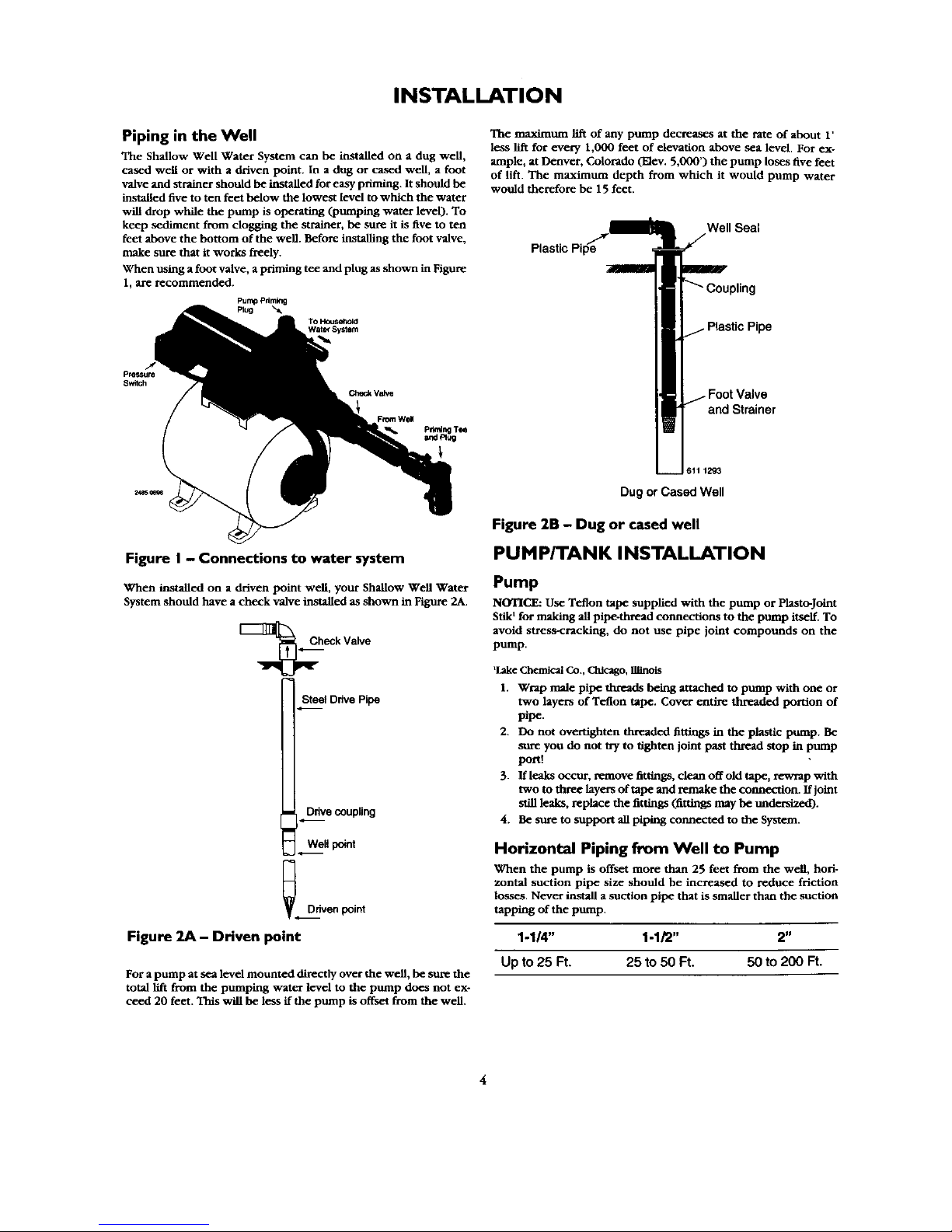
When u_mg a foot valve, a priming tee and plug as shown in Figure
1, are recommended.
FurnpPdming
Plug "X
To Household
Water System
pressure
Switch
Check Valve
From Well
Figure I - Connections to water system
When installed on a driven point well, your Shallow Well Water
System should have a check valve installed as shown in Figure 2A.
[_eck Valve
St_t Drive Pipe
_ Ddven point
Figure 2A - DHven point
For a pump at sea level mounted directly over the well, be sure the
total lift from the pumping water level to the pump does not ex-
ceed 20 feet. This will be less ffthe pump is offset from the well.
The maximum lift of any pump decreases at the rate of about 1'
less lift for every 1,000 feet of elevation above sea level. For ex-
ample, at Denver, Colorado (Elev. 5,000') the pump loses five feet
of lift. The maximum depth from which it would pump water
would therefore be 15 feet.
Plastic Pipe
Well Seal
and Strainer
611 1293
Dug or Cased Well
Figure 2B - Dug or cased well
PUMP/TANK INSTALLATION
Pump
NOTICE: Use Teflon tape supplied with the pump or Plasto-Jo'mt
Stik t for making all pipe-thread connections to the pump itself. To
avoid stress-cracking, do not use pipe joint compounds on the
pump.
'lake Chemical Co., Chicago,_Inois
1. Wrap male pipe threads being attached to pump with one or
two layers of Teflon tape. Cover entire threaded portion of
pipe.
2. Do not overtighten threaded fittings in the plastic pump. Be
sure you do not try to tighten joint past thl_ad stop in pump
portt
3. If leaks occur, remove fittings, clean off old tape, rewrap with
two to three layers of tape and remake the connection. If joint
still leaks, replace the fittings (fittings may be under_tzed).
4. Be sure to support all piping connected to the System.
Horizontal Piping from Well to Pump
When the pump is offset more than 25 feet from the well, hori-
zontal suction pipe size should be increased to reduce friction
losses. Never install a suction pipe that is smager than the suction
tapping of the pump.
1-1/4" 1-1/2" 2"
Up to25 Ft. 25 to 50 Ft. 50 to 200 Ft.
INSTALLATION
Discharge Pipe Sizes
xXrhen the pump is some distance from the house or point of water
use, the discharge pipe size should be increased to reduce pressure
losses caused by friction.
1" 1-1/4" 1-1/2"
Up to25 Ft. 25 to 100 Ft. 100 to 600 Ft.
Tank
Tank is pre-charged with 40 pounds per square inch (PSI) air pres-
sure at the factory. Your tank requires an air charge of 30 PSI for
proper operation; check tank pressure with tire gauge to deter-
mine if air charge needs adjustment. Tank pre-charge should be
checked annually; see instructions at right.
In areas where the temperature is high for long periods of time, the
tank pre-charge pressure may increase. This may reduce the tank
drawdown (amount of water available per cycle). If this occurs, re-
duce the pre-charge pressure to match the pump cut-in setting of
the pressure switch (normally 30 PSI).
It is necessary to flush all air out of the piping system mad water
reservoir portion of the pre_harged tank. This is required on new
installations, pumps requiring repriming and pumps that have been
disassembled for service. Do this as follows:
1. Open faucets furthest from tank and allow pump to operate.
2, Air in the system will cause a sputtering flow; allow faucets to
run until you have a steady, air free s_.
3. Open and close faucets repeatedly until you are sure all air has
been removed.
4. If stream does not become steady, air may be leaking into the
system; check for leaks in the piping on the suction side of the
pump.
NOTICE: To prevent watedogging, check tank air charge annually.
To Check Tank Air Charge
if drawdown (amount of water available per cycle) decreases sig-
nificantly, check as follows:
1. To check air charge in tank, shut off electric power to pump,
open faucet near tank, and drain completely.
2. At the air valve in top of tank, check air pressure with standard
tire gauge. Air pressure should be the same as the turn on pres-
sure of the pressure switch (30 PSI).
3. If the air pressure is below 30 PSI, add air to the tank. Use an
air compressor or a portable air storage tank.
4. Use soap or liquid detergent to check for air leaks around air
valve. Continuous bubbling indicates a leak. If necessary, install
new core in air valve. This is the same as those used for auto-
mobile tubeless tires.
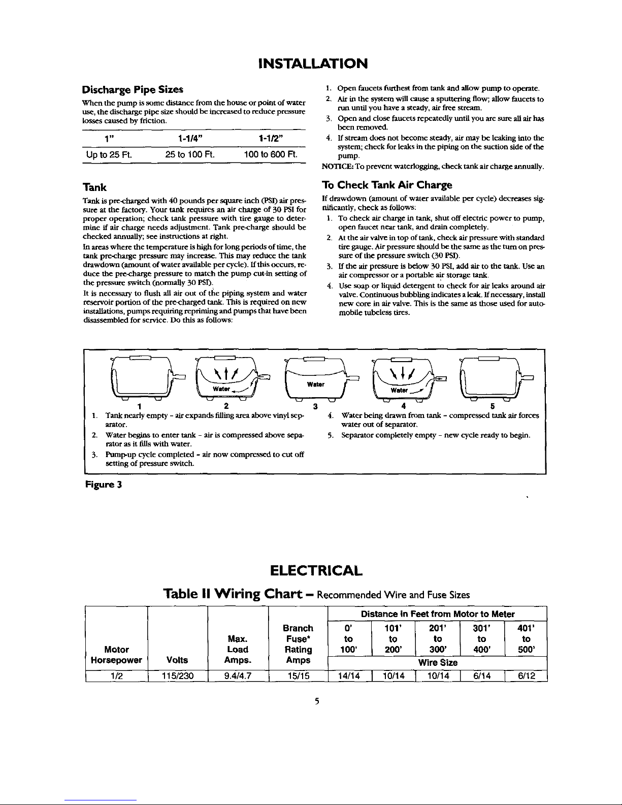
1 2
1. Tank nearly empty - air expands filling area above vinyl sep-
arator.
2. Water begins to enter tank - air is compressed above sepa-
rator as it fills with water.
3. Pump-up cycle completed - air now compressed to cut off
setting of pressure switch.
3 4 5
4. Water being drawn from tank - compressed tank air force,,
water out of separator,
5. Separator completely empty - new cycle ready to begin.
Figure 3
Motor
Horsepower
I/2
ELECTRICAL
Table II Wiring Chart - Recommended Wire and Fuse Sizes
Volts
115/230
Max.
Load
Amps.
9,4/4.7
Branch
Fuse*
Rating
Amps
15/15
Distance in Feet from Motor to Meter
0' 101' 201' 301' 401'
to to to to to
100' 200' 300' 400' 500'
Wire Size
14/14 10/14 10/14 6/14 6/12
 Loading...