

Sears Craftsman 113.274600C Owner's Manual

Save
this
manual
fo
r futur
e reference
SEAIRlS
owner's
manual
STOCK NO.
09
27460
MODEL NO.
113.27 4600C
Serial
Number
___
_
Model and seri
al
number may be found
on
th
e motor cover.
You should reco
rd both
model a
nd seri
al numb er
in a safe
pl
ace for
future us
e.
FOR YOUR
SAFETY:
READ
ALL
INSTRUCTIONS
CAREFULLY
S.IEA/RlS
/CIA
FTS
M A
N~o
'
DUAL
VOLTAGE
10-INCH
BELT
DRIVE
TABLE
SAW
•
Assembly
• Operati
on
• Repair Parts
Sold by: SEARS CANADA INC., TORONTO, ONT ARlO, CANADA
M5B
288
Pa
rt
No. SP5797 A Form No. SP 5797A
Printed in Canada 9/95
FULL TWO YEAR WARRANTY ON CRAFTSMAN TOOL
If
this Craftsman Tool fails to operate within two years from date of purchase, retu
(Sears) store and "Sears" will repair it, free ol charge.
If
this tool is used f
This warranty is in addit ion to any statutory warranty.
or
rental purposes this warranty applies for only 90 days from the date of purchase.
SEARS CANADA INC., TORONTO, ONT ARlO, CANADA
rn
it to the nearest Sears Canada Inc.
MSB
2B8
SAFETY INSTRUCTIONS FOR THE TABLE
SAFETY SIGNAL WORDS
Safety signal wor
information in the
signal words, DANGER, WARNING
the level of risk.
~
DANGER:
someone WILL be seriously injured or killed.
~
WARNING: If the safety information is not followed,
someone COULD be seriously injured
~
CAUTION: If the safety information is not followed,
someone MAY be injured.
Safety is a combination of common sense, staying alert
and knowing how your table saw works. Read this
manual to understand this saw.
Read
and
instructions
BEFORE
USING THE SAW:
WARNING:
serious, permanent injury, do not
until the following steps have been satisfactorily
completed.
• Completely assemble and align saw (See pages 12-38)
• Learn the use and function of the ON guard, spreade
table insert and blade elevation and bevel controls.
page 39)
(See
• Review and understand all safety instructions and
operating procedures in
Review
•
(See page 60)
• Find and read all the warning labels found on the
front of saw (shown below).
WHEN INSTALLING OR MOVING THE SAW:
Avoid dangerous environment.
• Use the saw in a dry, indoor place protected from
rain.
• Keep work area well lighted.
To avoid injury from unexpected saw movement:
• Bolt
or
there is plenty of room to handl e and properly
support the workpiece.
• Support the saw so the table is level and the saw
does not rock,
When using a table extension on any side of the
•
ds
are used to draw attention to safety
manual and on the table saw. The
or
CAUTION, tell
If
the safety information is not followed,
or
killed.
follow
all
safety
information
and
To avoid mistakes that could cause
plug the saw
OFF-
r,
anti-kickback device, mitre gauge,
th
is manual.
of
the maintenance methods for this saw.
in
switch,
clamp the saw on a firm level surface where
or
slide.
• Put the saw where neither operators or bystande
• GROUND THE
•
• To avo
• Never stand on tool. Serious injury could occur
BEFORE EACH USE:
Inspect
• To
• Check for alignment of moving parts, binding of
• If any part is missing, bent,
• Replace damaged, miss ing, or failed
• Use the sawblade guard, spreader, and anti-kick-
•
' Ma
SAW----------
saw, bolt the saw to a stat ionary surface or prop up
the outer end of the extension from the floor or bench
top to keep the saw from tipp i
must stand in line with the saw blade.
SAW-
Modei113-274600C has
approved 3-conductor cord and a 3-prong grounding type plug. The plug fits grounding type outlets
designed for 120 volt 15 amp circuits. The green
conductor
in
the cord is the grounding wire. To avoid
electrocution, never connect the green
terminal.
The saw
is
shipped factory wired for 120V operatio
To change the motor to 240V see owners manual for
correct procedure.
id
injury from electrical shock, make sure
your fingers do not touch the plug's metal prongs
plugging in or unp lugging the saw.
when
the to
ol
tips
or
you accidental
Do not store anything above or near the tool where
anyone might stand
on
your saw.
avoid
injury from accidental starti
unp
lug
the saw and
or
removing
ing
the setup or adjusting anyth
remove
the guard, changing the cutting tool,
moving parts, breakage of parts, mounting, and any
other conditions that may affect the way it works.
electrical parts don't work properly, turn the saw
any
off and
usi
back
unplug the saw.
ng
the saw again.
pawls for anythru-sawing (whenever the blade
comes through the top of the workpiece). Make sure
the spreader is in line with the sawblade and the ant
kickback pawls work properly.
Remove adjusting keys and wrenches.
Form habit of checking for
adjusting wrenches from
k€
sure all clamps and locks are tight and no
ha
parts
ve excessive play.
ng.
wi
re
to
ly
hit the cutting too
the tool to reach them.
ng,
turn
switch
the
swi
tch
key
before
raising
chang
ing.
or
broken in any way, or
parts before
an
d removing keys and
tool before turning it on.
an
a live
off
rs
n.
if
l.
,
-
i-
. :
·:
:t
i. . ~ :
······
::
·:;.
::
:' •
,•'
2
To
avoid
injury
(kickback
Use
only recommended accessories.
from
and
throwback):
jams,
slips
or
thrown
pieces
• Follow the instructions that come with the acc esso-
Th
ries.
e use of improper accessories may cause
risk of injury to persons.
• Choose the right bfade or cutting accessory for the
material and the type of cutting you plan to do.
• Never use grinding wheels, abrasive cut-off wheels,
friction wheels (metal slitting blades) wire wheels or
buffingwheel. They can fly apart explosively.
Choose
• To avoid cutting tool failure
and
inspect
your
cutting
tool
and thrown shrapnel
(broken pieces of blade), use only 1
blades
or
other cutting tools marked for speed of
carefully.
0" or smaller
3450 rpm or higher.
• Always use unbroken, balanced blades designed to
fit this saw's
5/8" arbor.
• When thru-sawing, (making cuts where the blade
comes through the workpiece top) always use a
inch diameter blade. This keeps the spreader
10
in
closest to the blade.
•
Do
not overtighten arbor nut. Use arbor wrenches to
"snug"
it
securely.
• Use only sharp blades with properly set teeth. Consult a professional blade sharpener when in doubt.
• Keep blades clean of gum and resin.
• Adjust table inserts flush with the table top. Never
use the saw without the proper insert.
• Make sure all clamps and locks are tight and no
parts have any excessive play.
Inspect
your work
area.
• Keep work area clean.
• Cluttered areas and benches invite accidents. Floor
be
must not
slippery from wax
• To avoid burns or other fi
li
saw near flammable
• To avoid inju
ry,
quids, vapors or gases.
don't
do
work on the table while the blade is spinning.
th
row anything hitting the blade.
work
.
Plan
cut or
your
or
sawdust.
re
damage, never use the
layout, assembly, or setup
It
could
• Plan ahead to protect your eyes, hands, face and
ears.
• Use the right
do a job
for
Dress
•
Do
not wear loose clothing, gloves, neckties or
tool-
Don't force tool or attachment to
it
was not designed for.
safety:
jewelry (rings, wrist watches). They can get caught
and draw you into moving parts.
• Wear nonslip footwear.
• Tie back long hair.
• Roll !ong sleeves above the elbow.
• Noise levels vary widely. To avoid possible hearing
damage, wear ear plugs or muffs when using saw for
long periods of time.
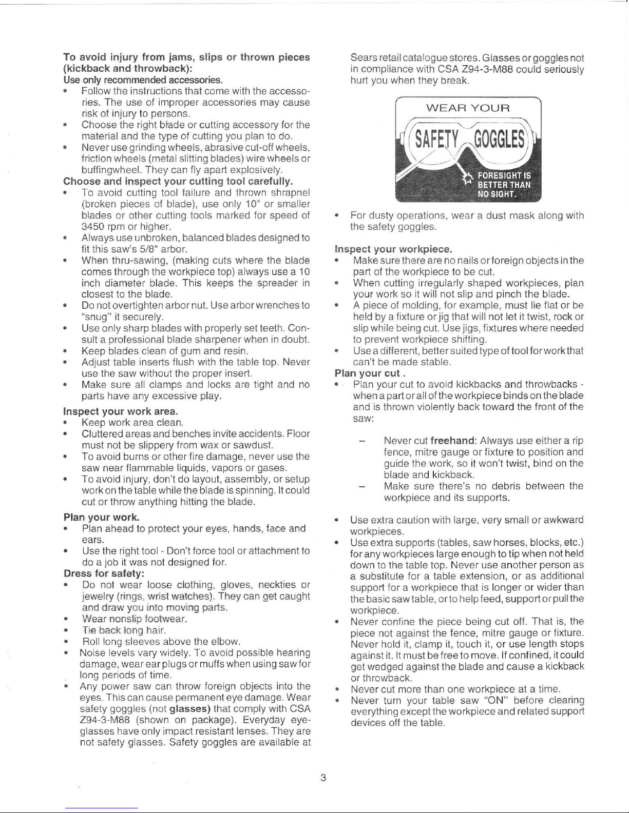
• Any power saw can throw foreign objects into the
eyes. This can cause permanent eye damage. Wear
safety goggles (not
glasses)
that comply with CSA
Z94-3-M88 (shown on package). Everyday eyeglasses have only impact resistant lenses. They are
ai
not safety glasses. Safety goggles are av
lable at
Sears retail catalogue stores. Glasses
in compliance with
CSA Z94-3-M88 could seriously
or
goggles not
hurt you when they break.
WEAR
For dusty operations, wear a dus t mask along with
•
YOU
R
the safety goggles.
Inspect
• Make sure there are no nails
your
workpiece.
or
foreign objects
in
the
part of the workpiece to be cut.
• When cutting irregularly shaped workpieces, pl
your work so it wi
ll
not slip and pinch the blade.
• A piece of molding, for example, must lie flat or
held by a fixture
or jig
that will not let it twist, rock or
an
be
slip while being cut. Use jigs, fixtures where needed
to prevent workpiece shifting.
• Use a different, better suited type of tool for work that
can't be made stable.
your
cut
Plan
.
• Plan your cut to avoid kickbacks and throwbacks when a
and
pa
rt or all of the workpiece binds on the blade
is
thrown violently back toward the front of the
saw:
fr
Never cut
eehand: Always use either a rip
fence, mitre gauge or fixture to position and
guide the wor
so it won't twist, bind
on
the
k,
blade and kickback.
ri
Make sure there's no deb
s between the
workpiece and its supports.
• Use extra caution with large, very small or awkward
workpieces.
• Use extra supports (tables, saw horses, blocks, etc.)
el
for any workpieces large enough to tip when not h
d
down to the table top. Never use anot her person as
a substitute for a table extension, or as additional
support for a workpiece that is longer or wider than
or
the basic saw table,
to help feed, support or pull the
workpiece.
• Never confine the piece being cut off. Tha t
piece not against the fence, mitre gauge
Never hold it, clamp it, touch it,
aga
in
st it. It must
be
free to move. If confined, it could
or
use length stops
get wedged against the blade and cause a k
or
fixture.
ic
is,
the
kback
or throwback.
•
Ne
ver cut more than one workpiece at a time.
•
Ne
ver turn your table saw
"ON"
before clearing
everything except the workpiece and related support
devices off the table.
3
Plan the way you will push the workpiece through.
• NEVER pull the workpiece through. Start and
finish the
cut
from the front of the table saw.
• NEVER put your fingers or hands
in
the path of
the sawblade
or
other cutting tool.
• NEVER reach
in
back of the cutting tool with either
hand to hold down or support the workpiece, remove
wood scraps,
or
for
any other reason.
• Avoid hand positions where a sudden slip could
cause fingers
or
hand to move into a sawblade
or
other cutting tool.
• Don't overreach. Always keep good footing and
balance.
..
Push the workpiece against the rotation
of
the blade.
Never feed material into the cutting tool from the rear
of the saw.
• Always push the workpiece all the
way
past the
sawblade.
• As much as possible, keep your face and body to
one side of the sawblade, out of line with a possible
kickback
or
throwback.
• Set the cutting tool as l
ow
as possible for the cut
you're planning.
• Never turn the saw "ON" before clearing the table of
all tools, wood scraps, etc. except the workpiece
and related feed
or
support devices for the cut
planned.
Avoid accidental starting
• Make sure switch is
"OFF"
before plugging saw
in.
WHENEVER SAWBLADE IS SPINNING
WARNING:
Don't
let
familiarity
(gained from
fre-1
quent use of your table saw) cause a careless
mistake. Always remember that a careless
fraction of a second is enough to cause a severe
injury.
• Before actually cutting with the saw, watch it while it
runs
for
a short while.
If
it makes an unfamiliar noise
or
vibrates a lot, stop immediately. Turn the saw off.
Unplug the saw.
Do
not restart until finding and fixing
the problem.
• Make sure the top of the arbor
or
cutting tool turns
toward the front
of
the saw.
Keep children away.
• Keep all visitors should be kept a safe distance from
the table saw.
• Make sure bystanders are clear of the saw and
workpiece.
Don't force tool.
• Let the blade reach full speed before cutting.
•
It
will do the job better and safer
at
its designed rate.
• Feed the workpiece into the saw only fast enough to
let the blade
cut
without bogging down or binding.
Before freeing any jammed material:
• Turn switch "OFF" .
•
Unplug the saw.
• Wait for all moving parts to stop.
• Check blade, spreader and fence for proper alignment before starting, again.
To avoid throwback of small , cut off pieces:
• Use the guard assembly.
4
To remove pieces beneath or trapped inside the
guard.
• Turn saw off.
• Remove
svvitch
key.
• Unplug saw.
• Wait for blade to stop before lifing the guard.
Before leaving the saw .
• Turn saw off.
• Wait for blade to stop spinning.
• Unplug the saw.
• Make workshop childproof. Lock the shop. Disconnect master switches. Remove the
yellow switch
key.
Store it away from children and others not
qualified to use the tool.
Additional Safety Instructions For:
Rip Type Cuts.
•
•
•
•
•
•
•
•
Never use the mitre gauge when ripping .
Use a push stick whenever the fence is 2 or more
inches from the blade.
When thru-sawing, use an auxiliary fence and push
block whenever the fence must be between 1/2 inch
and 2 inches from the blade.
Never thru-saw
rip
cuts narrower than 1/2 inch. (See
"Basic Saw
Operation Using The Rip Fence" section)
Never rip anything shorter than 1
0" long .
When using a push stick or push block the trailing
end of the boa
rd
must be square. A push stick or
block against an uneven end could slip off or push
the work away from the fence.
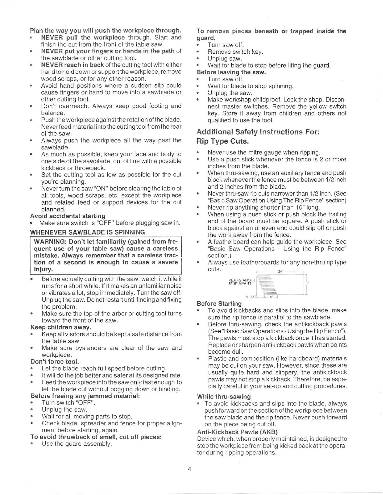
A featherboard can help guide the workpiece.
See
"Basic Saw Operations - Using the Rip Fence"
section.)
Always use featherboards for any non-thru rip type
cuts.
24
""-
l
~·
4-1/ 2
".l
+-
5"~7----..-J
Before Starting
• To avoid kickbacks and slips into the blade, make
sure the rip fence is parallel to the sawblade.
• Before thru-sawing, check the antikickback pawls
(See "Basic Saw Operations- Using the Rip Fence").
The pawls must stop a kickback once it has started.
Replace or sharpen anti kickback pawls when points
become
dull.
• Plastic
and composition (like hardboard) materials
may be cut
on
your saw. Howeve
r,
since these are
usually quite hard and slippery, the antikickback
pawls may not stop a kickback. Therefore, be especially careful in your set-up and cutting procedures.
While thru-sawing
• To avoid kickbacks and slips into the blade, always
push forward on the section of the workpiece between
the saw blade and the rip fence. Never push forward
on
the piece being cut off.
Anti-Kickback Pawls (AKB)
Device which, when properly maintained, is designed to
stop the workpiece from being kicked back at the operator during ripping operations.
Additional Safety Instructions Fer:
Cross Cut Type Cuts
• Never use the rip fence when crosscutting .
• An auxiliary wood facing attached to the mitre gauge
can help prevent workpiece twisting and throwbacks.
Attach it to the holes provided. Make the facing long
enough and big enough to support your work. Make
sure, however,
guard. (S
Before starting
• Use jigs or fixtures
extend across the
ee
page 40)
it
will not interfere with the sawblade
to
help hold any
full length of the mitre gauge face
p1ece
too small to
t.
during the cu
gauge and workpiece and helps keep your hands
away from the blade .
While cutting
• To avoid blade contact, always hold the mitre gauge
as shown
Mitre
Gauge".
This lets you properly hold the mitre
in
the "Basic Sa w Ope rations - Using the
GLOSSARY
Arbor
The shaft
Bev
An angle cutting operation made through the face of the
workpiece.
Compound Cut
A simultaneous bevel and mitre cutting operation.
Crosscut
A cutting or shaping operation made across the width of
the workpiece.
Da
do
A non-through cut which produces a square sided notch
or trough in the workpiece.
Featherboard
A device which can help guide workpieces during rip
type operations.
Freehand
Performi
fixture, hold down or other proper device to keep the
workpiece from twisting during the cut. Twisting of the
workpiece can cause it to be thrown.
Gum
A sticky, sap based residue from wood products.
Heel
Misalignment of the saw blade such that the blade is not
parallel to the mitre gauge groove.
Ke
rf
The amount of material removed by the blade in a
through cut
through or partial cut.
Ki
ckback
An uncontrolled grabbing and throwing of the workpiece
back toward the front of the saw .
Leading End
q-he
operation,
Mitre Cut
An angle cutting operation made across the width of the
workpiece.
Molding
A non-through cut which produces a special shape
on
el
Cut
ng
end of the workpiece which, during a rip type
is
OF
TERMS FOR WOODWORKING
which a cutting tool is mounted.
a cut without using a fence, mitre gauge,
or
the slot produced
pushed into the cutting tool first.
by
the blade in a non-
in
the
workpiece used for joining
Ploughing
Ploughing
workpiece, using the fence. USE proper holddowns and
feed devices.
Push Stick
A device used to feed the workpiece through the saw
during narrow ripping type operations and help keep the
operator's hands
Push Block
A device used for ripping type operations too narrow to
allow use of a push stick.
Rabbet
A notch
Resin
A sticky, sap base substance that
Revolutions Per Minute (RPM)
The number of turns completed
one minute.
Rip Cut
A cutting operation along the length
Sawblade Path
The area of the workpiece or table top directly in line with
the part of the workpiece which
by the blade.
Set
The distance that the tip of the sawblade tooth is bent (or
set) outward from the face of the blade.
Throw-Back
Throwing of pieces in a manner simila r to a kickback.
Thru-Sawing
Any cutting operation where the blade extends com-
pletely through the thickness of the workpiece.
Trailing End
The workpiece end last cut by the blade in a ripping
operation.
Workpiece
The item on which the cutting operation is being done.
The surfaces of a workpiece are
as faces, ends, and edges.
is
grooving with the grain
well away from the blade.
in
the edge
or
of
a workpiece.
decoration.
the
long way of the
has
hardened.
by
a spinn ing object in
of
the workpiece.
will be,
or
has been, cut
com
mon ly referred to
5
MOTOR SPECIFICATIONS AND ELECTRICAL REQUIREMENTS
----
WARN ING: Do not use blower
or
was
hin
g ma-
chi
ne
motors
or
any
motor with
an
automat
ic
res
et
overl
oad
protecto
r. They
can
start
up
by
th
emselves and you cou
ld
get injured.
POWER SUPPLY- 120 VOL TS/240
VOL
TS
Capacitor Start
Capacitor Run
Motor
Specific
ati
ons
The A-C motor used in this saw is a non-reversible type
having the following specifications:
Voltage ...........................
..
........................... 120/240
Hertz (cycles) .......................................................
60
Phase ............................................................. Single
RPM ......................................
....
....................... 3450
Your
saw
is wired
for
120 volts and is
equipped
with
a 3
conductor
cord
and grounding ty
pe plug
whi
ch
ha
s a grounding
pro
ng
approved by
Unde
rwrit
ers
L
aboratories and
Can
adi
an
Standards Assoc
iation.
See
Fig
. A.
CHANGING MOTO R
VOLT
AGE
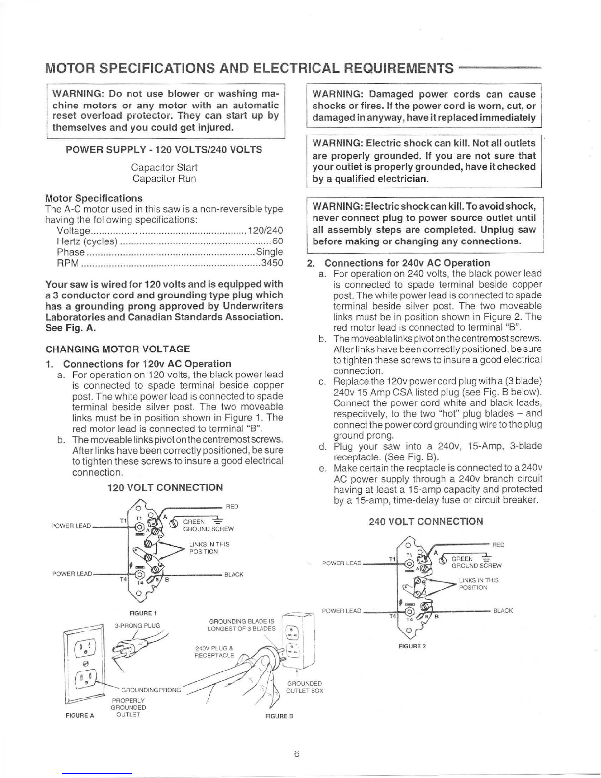
1.
Connections
for
120v
AC
Ope
rati
on
a.
For operation on 120 volts, the black power lead
is
connected to spade terminal beside copper
post. The white power lead is connected to spade
terminal beside silver post. The two moveable
links must be in position shown in Figure 1. The
red motor lead is connected to terminal
"B
".
b.
The moveable links pivot on the
centrer:~ost
sc
rews.
After links have been correctly positioned , be sure
to tighten these screws to insure a good electrical
connection.
1
20
VOLT
CONNECTION
FIGURE 1
3·PRONG PLUG
~
GROUNDING PRONG
PROPERLY
GROUNDED
FIGURE
A OUTLET
J_
GREEN
GROUND SCREW
LI
NKS IN THIS
POSITION
GROUNDING
BLADE IS
LONGEST
OF
3 BLADES
FIGURE B
6
I
WARNING: Damaged
powe
r c
ords
can ca
use
1
sh
ocks
or
fires. If the
power
cord
is
worn, cu
t,
or
!
damaged
in
anyway
, have
it
replaced
immediately
WARNING : Electr
ic
shock
can
kil
l.
Not
all
outlets
are pr
operly
grou
nded. If
you
are
not
sure
that
y
our outl
et
is
properly
grounded, have
it
check
ed
by a
qu
alified ele
ctr
ician.
WARNING:
Electric
shock
can
kill
. To
avoid
shock
,
nev
er
connect pl
ug to p
owe
r so
urce
outlet
until
a
ll ass
embly
steps
are
comple
ted.
Unplug
saw
before
making
or chang
ing a
ny connections.
2. C
onnectio
ns f
or
240v AC
Operation
a. For operation on 240 volts, the black power lead
is connected to spade terminal beside copper
post. The white power lead is connected to spade
terminal beside silver post. The two moveable
links must
be
in
position shown in Figure
2.
The
red motor lead is connected to terminal
"B
".
b.
The moveable links pivot
on
the centremost screws.
A
ft
er links have been correctly positioned, be sure
to tighten these screws to insure a good electrical
connection.
c. Replace the
120v power cord plug with a
(3
blad
e)
240v 15 Amp CSA listed plug (see Fig. B below).
Connect the power cord white and black leads,
respecitvel
y,
to the two "hot" plug bl
ades-
and
connect the power cord grounding wi
re
to the plug
ground prong.
d. Plug your saw into a
240v, 15-Amp, 3-blade
receptacle. (See Fi
g.
B).
e. Make certain the recptacle is connected to a
240v
AC
power supply through a 240v branch circuit
having at least a 15-amp capacity and protected
by a 15-amp, time-delay fuse
or
circuit breaker.
240
VOLT
CONNECTION
FIGURE 2
WARNING:
To
avoid
electrical
shock,
do
not
per-
mit
fingers
to
touch
the
terminals
of
the
plug,
when
installing
or
removing
the
plug
to
or
from
the
outlet.
WARNING:
Failure
to
properly
ground
this
power
tool
can
cause
electrocution
or
serious
shcok,
particularly
when
used
in
damp
locations,
or
near
metal
plumbing.
If
shocked,
your
reaction
could
cause
your
hands
to
hit
the
cutting
tool.
MOTOR
THERMAL
OVERLOAD
PROTECTOR
CAUTION:
To
avoid
motor
damage,
this
motor
should
be
blown
out
or
vacuumed
frequently
to
prevent
sawdust
buildup
which
will
interfere
with
normal
motor
ventilation
.
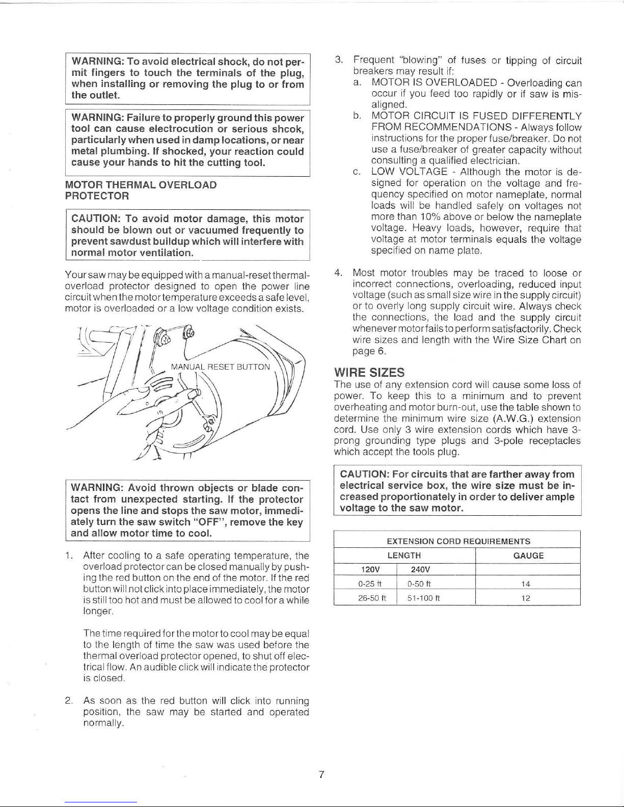
Your saw may be equipped with a manual-reset thermaloverload protector designed to open the power line
circuit when the motor temperature exceeds a safe level,
motor is overloaded or a low voltage condition exists.
WARNING:
Avoid
thrown
objects
or
blade
con-
tact
from
unexpected
starting
. If
the
protector
opens
the
line
and
stops
the
saw
motor,
immedi-
ately
turn
the
saw
switch
"OFF",
remove
the
key
and
allow
motor
time
to
cool.
1.
After cooling to a safe operating temperature, the
overload protector can be closed
manually by pushing the red button on the end of the motor. If the red
button will not click into place immediately, the motor
is
still too hot and must be allowed to cool for a while
longer.
The time required for the motor to cool may be equal
to the length of time the saw was used before the
thermal overload protector opened, to shut off
electrical flow. An audible click will indicate the protector
is closed.
2.
As soon as the red button will click into running
position, the saw may be started and operated
normally.
7
3.
Frequent "blowing" of fuses or tipping of circuit
breakers may result
if:
a. MOTOR IS OVERLOADED
-Overloading
can
occur if you feed too rapidly
or
if saw is mis-
aligned.
b.
MOTOR CIRCUIT IS FUSED DIFF
ERENTLY
FROM
RECOMMENDATIONS-
Always follow
instructions for the proper fuse/b reaker.
Do
not
use a fuse/breaker
of
greater capacity without
consulting a qualified electrician.
c.
LOW VOLTAGE - Although the
motor
is
designed for operation on the voltage and frequency specified on motor nameplate, normal
loads
will be handled saf
ely
on voltages not
more than 10% above or below the nameplate
voltage. Heavy loads, however, require that
voltage at motor terminals equals the voltage
specified on name plate.
4. Most motor troubles may be traced to loose or
incorrect connections,
ov
erloading, reduced input
voltage (such as
small size wire in the supply circuit)
or to overly long supply circuit wire. Always check
the connections, the load and t
he
supply circuit
whenever motor
fails to perform satisfactorily . Check
wire sizes and length with the Wire Size Chart on
page
6.
WIRE SIZES
The use of any extension cord will cause some loss of
power.
To
keep this to a minimum and to prevent
overheating and motor burn-out, use the table shown to
determine the minimum wire size (A .W.G.) extension
cord. Use only 3 wire extension
co
rds which have 3prong grounding type plugs and 3-pole receptacles
which accept the tools plug.
CAUTION:
For
circuits
that
are
farther
away
from
electrical
service
box, the
wire
size
must
be in-
creased
proportionately
in
order
to
deliver
ample
voltage
to
the
saw
motor.
EXTENSION
CORD
REQUIREMENTS
LENGTH
GAUGE
120V
240V
0-25
tt
0-
50
tt
14
26-50
tt
51-100 tt 12
CONTENTS
WARRANTY ........................................................................ 2
Rip Fence .......
..
............................................................ 40
GENERAL SAFETY INSTRUCTIONS Mitre Gauge .................................................................. 40
FOR
TABLE SAWS ..................................................... 2-5
Blade Guard ............................
...
.................................
.40
GLOSSARY
OF
TERMS FOR
WOODWORK
ING .............. 5
Table Insert ..........
...
.................. .............. ...................... 40
MOTOR SPECIFICATIONS
AND ELECTRICAL
Removing and Installing Saw Blade ........................... .
41
REQUIREMENTS ........................................................... 6
Exact-1-Cut ....................................................................
41
Motor Specifications ..................................
...
................... 6
Micro-Adjust Rip Fence .......................... ......
......
.......... 42
Changing Mot
or
Voltage .................
....
............................ 6
BASIC SAW OPERAT I
ON
................................................ 42
Mot
or
Thermal
Ove
rload ................................................. 7 Work Feed Devices ...................................................... 42
Wire
Sizes ...........................
......
...................................... 7 Push Stick and Push Block .....................
.......
............... 42
UNPACKING
AND
CHECKING CONTENTS ...................... 8 Auxiliary Fence/Work Support ...................................... 43
Tools Needed .................................................................. 8 SAFETY INSTRUCT IONS FOR
List of Loose Parts ................
...................................
..
9-11
BASIC SAW OPERATIO NS ...............
......
..........
...
. .44-55
ASSEMBLY .................................................................. 12-38
Using the Mitre Gauge .................................................. 46
Installing Handwheels ................................................... 12
Crosscutting ......................................
..
.......................... 46
Checking
Table Insert ................................................... 12
Repetitive Crosscutting .........................................
..
...... 47
Checking
Blade Squareness to Table .............
....
......... 13
Mitre Crosscutting .......
..
...............
........
.........................
48
Assembling Steel
Saw
Base Cabinet .........................
..
13 Bevel Crosscutting ... ..................................................... 48
Installing Base Shelf ...................................................
..
14 Compound Mitre Cutting ..................................... .........
.48
Installing Front Panel Handle Brackets ......................... 14
USING THE RIP FENCE .....................................
......
....... .49
Installing Front Panel Levellers ..................................... 15
Ripping
..
.........
....
......................................................
49-51
Installing Rear Axle Brake Bar and Wheels ............. 16-17
Bevel Ripping Narrow Work ......
....
................................
51
Assembling Saw Base Brake System ..................... 17-18
Resawing ...........
..............................................
............. 52
Moun
ti
ng Saw to Saw Base ....... .........
....
...................... 19 Cutting Panels ...
...
..................
...
....................
..............
52
Installing Table Saw Dust Collector ......................... 20-21 Using Featherboards for Thru-Sawing ...................
.......
53
Attaching and Assembling Table Extensions ................ 22 Using Featherboards for Non-Thru Sawing .................. 53
Installing Table Extens ion Brackets ..........................
....
23
Rabbeting .............................................
..
.................... 54
Installing Front Rip Fence Guide Bar ....................... 24-25
Ploughing and Molding ................................................. 54
Installing Rear Fence Guide Bars ................................. 25
Dadoing ..................
....
...................... .................... , .......
55
Adjusting Rip Fence Guide Bars ...............................
....
26
Molding Cutting ....................................... ...................... 55
Installing Separator Channel ................................... 27-28
ADJUSTMENTS ................................................................ 56
Rip Fence
Alignment Adjustment ..................
......
......... 28
Mitre Gauge .......................................
.............
............
..
56
Rip Fence Lock Lever Adjustment ................................ 29 Heeling Adjustment or Parallelism
Assembl i
ng
Micro Adjust and Racks ....................... 29-30
of Sawblade to Mit
re
Gauge Groove ....................... 56-57
Installing Measuring Tapes and Indicat
or
................ 31-32
Installing Blade Guard ............................................. 33-35
Blade Tilt,
or
Squareness of Blade to Table .................
58
90 degree position .........................................
.............
..
58
Positioning Motor on Motor Mounting Base .................. 35
45 degree position .......................
..........
....................... 59
Preparing the Motor Before Mountin g ........................... 36
Tilt Mechanism ............................................................
..
60
Mounting Switch .......................... .......................
........
..
36
MAINTAINING YOUR TABLE SAW ........
......
.................... 60
Mounting Motor .................................. ........................... 37
Maintenance .....................
.....
...
.................................... 60
Installing Belt
Guard ................................................ 37-38
Lubrication
..
..................................................................
61
Securing Motor Wire .......
.......................... .................... 38
TROUBLE
SHOOTING ................................
....
.................. 62
GETTING
TO
KNOW
YOUR SAW ............................... 39-42
General .....
...
......
....
............
......
.................
....
................ 62
On-Off Switch ..............
....
.............................................. 39
Motor ..............................
..
.....................
....
.............. 62-63
Elevation Handwheel ....
...
.............. ...............................
40
REPAIR PARTS ... ..............................................
.......... 64-74
Tilt Handwheel ..............................................................
40
CUSTOMER RESPONSE ................................................. 76
Tilt Lock Handle ...............
............................................
.40
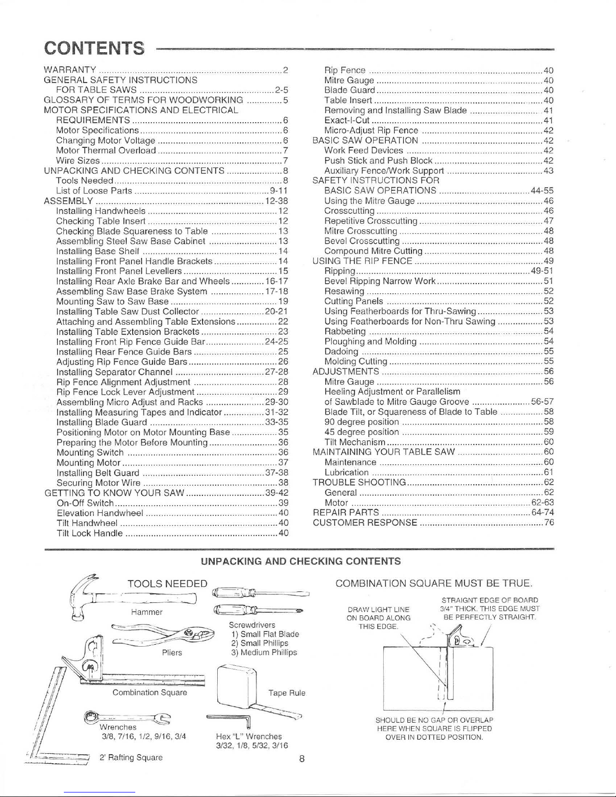
UNPACKING AND CHECKING CONTENTS
Combination Square
~
--~
Wre
nches
3/8, 7/16, 1/2, 9/
16
, 3/4
Screwdrivers
1)
Small Flat Blade
2)
Small Phillips
3) Medium Phillips
Tape Rule
Hex "L" Wrenches
3/32, 1/8, 5/32, 3/16
8
COMBINATI
ON
SQUARE
MUST
BE TRUE.
STRAIGNT EDGE OF BOARD
DR
AW LIGHT LINE 3/4" THICK. THIS EDGE MUST
ON
BOA
RD
ALONG BE PERFECTLY STRAIGHT.
THIS
EDGE
.
~-~
;~
Jf
5<j
I I
I I
I j
I I
lJ
SHOULD BE NO GAP OR OVERLAP
HERE WHEN SQUARE IS FLIPPED
OVER IN
DOTTED POSITIO
N.
Separate all parts from packing materials and check
each one with the
illustration and the list of Loose Parts
to make certain all items are accounted for, before
discarding any packing
material.
WARNING: If
any
parts are missing, do not at-
tempt to assemble the table saw
or
plug in the
power cord or turn
the
switch on until
the
missing
parts are obtained and are
installed correctly.
Remove the protective oil that is applied to the table top
and edges of the
table. Use any ordinary household type
grease and spot remover.
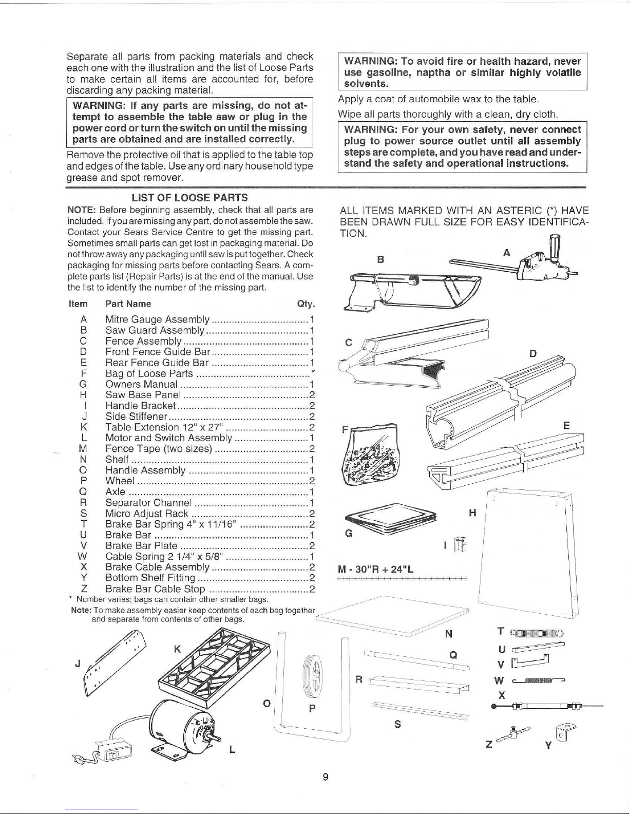
LIST
OF
LOOSE PARTS
NOTE:
Before beginning assembly, check that all parts are
included.
If
you are missing any part, do not assemble the saw.
Contact your Sears Service Centre to get the missing part.
Sometimes
small parts can get lost in packaging material. Do
not throw away any packaging
until saw is put together. Check
packaging for missing parts before contacting Sears. A complete parts list (Repair Parts) is at the end of the manual. Use
the
list to identify the number of the missing part.
Item Part Name Qty.
A Mitre Gauge Assembly .................................. 1
B
Saw Guard Assembly .................................... 1
C Fence Assembly ............................................ 1
D Front Fence Guide Bar .................................. 1
E Rear Fence Guide Bar ................................
..
1
F Bag of Loose
Parts ........................................ *
G Owners Manual ............................................. 1
H
Saw Base Panel ............................................ 2
I Handle Bracket.. ............................................ 2
J Side Stiffe ner ...............
..
................................ 2
K
Table Extension 12" x 27" ............................. 2
L Motor and Switch Assembly .......................... 1
M Fence Tape (two sizes) ....................
..
........... 2
N
Shelf .............................................................. 1
0 Handle Assembly .......................................... 1
P Wheel ............................................................ 2
Q Axle ..........................................
.....
...
............. 1
R Separator
Channel ........................................ 1
S Micro Adjust Rack ......................................... 2
T Brake Bar Spring 4" x
11
/16" ........................ 2
U Brake Bar ...................................................... 1
V Brake Bar
Plate ............................................. 2
W
Cable Spring 2 1/4" x 5/8" ............................. 1
X Brake
Cable Assembly .................................. 2
Y Bottom Shelf Fitting ....................................... 2
Z Brake Bar Cable Stop ................................... 2
WARNING: To avoid fire
or
health hazard, never
use gasoline, naptha or similar highly
volatile
solvents.
Apply a coat of automobile wax to the table.
Wipe all parts thoroughly with a clean,
dry
cloth.
WARNING: For your own safety,
never
connect
plug
to
power source outlet until all assembly
steps
are
complete, and you
have
read
and
under-
stand the safety and operational instructions.
ALL ITEMS MARKED WITH AN ASTERIC (*) HAVE
BEEN DRAWN FULL
SIZE FOR
EASY
IDE
NTI
FICA-
TION.
B
H
M-
30"R +
24"l
• Number varies; bags can contain other smaller bags.
~--------
Note:
To
make assembly easier keep contents of each bag together
__.-
. ..-----
~
,o,1
·-
J
and separate from contents of other bags.
C::::.:::::::::--...._
~
~
-
~
N
.·
.1·---
-- ·· N
~~
0
p
l
9
R
c=====-=============
~
-----=====::r
-""
~
s
T
<Cilfl
«lll
llllll
llll
lll
lllllillllllllt!fJ
u
~
v
~
w c
MWIH:t~
X
z
~
y
~
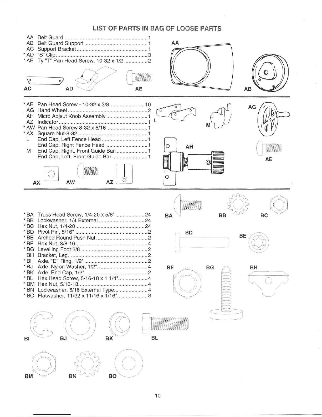
LIST OF PARTS IN BAG OF LOOSE PARTS
AA Belt Guard ........................................................ 1
AB
Be
lt Guard Support ...................
...
..................... 1
A.~A~::=~~==j
AC Support Bracket.. .............................................. 1
:::=
*AD
"S" Clip .................................................... .......... 3
* AE Ty
"T" Pan Head Screw, 1 0-32 x 1/2 ................ 2
\o_~O)
AC
AD
* AE
Pan Head
Screw-
10-32 x 3/8 ....................... 10
~
cj)
AG Hand Wheel ............
...
....................................... 2 o o
AH Micro Adjsut Knob Assembly ............................ 1 ° .
* AZ Indicator ............................................................ 1 L M . .
AW Pan Head Screw 8-32 x 5/16 ........................... 1
*AX
Square Nut-8-32 ............................................... 1
L End Cap, Left Fence Head ............................... 1
End Cap, Right Fence Head .................
...
........ 1
AH
M End Cap, Right, Front Guide Bar ...................... 1
End Cap, Left, Front Guide Bar
..
...................... 1
(JJ
~~~~~~~
~~t
AE
* BA Truss Head Screw, 1/4-20 x 5/8" .................... 24
BA
(}-
BC
©
*
88
Lockwasher, 1/4 External ............................... 24
*
8C
Hex Nut, 1/4-20 .............................................. 24
*
80
Pivot Pin, 5/16"
...
.............................................. 2
*
BE
Arched Round Push Nu
t..
................................. 2
* BF Hex Nut, 3/8-16 ...............................................
.4
*
8G
Levelling Foot 3/8 ............................................. 2
8H Bracket,
Leg ..................................................... 2
*
81
Axle, "E" Ring, 1/2" ........................................... 2
* 8J
Axle, Nylon Washer, 1/2" .................................
.4
BH
* BK Axle, End Cap, 1/2" .......................................... 2
* BL Hex Head Screw, 5/16-18 x 1
1/4" ..................
.4
* BM Hex Nut, 5/16-18
....
.......................................
..
.4
.
--
-
--,
7
<,,._
()
*
8N
Lockwasher, 5/16 External Type .....................
.4
* BO Flatwasher, 11/32 x 11/16 x 1/16" .................... 8
~I
BL
~
BM
~
10
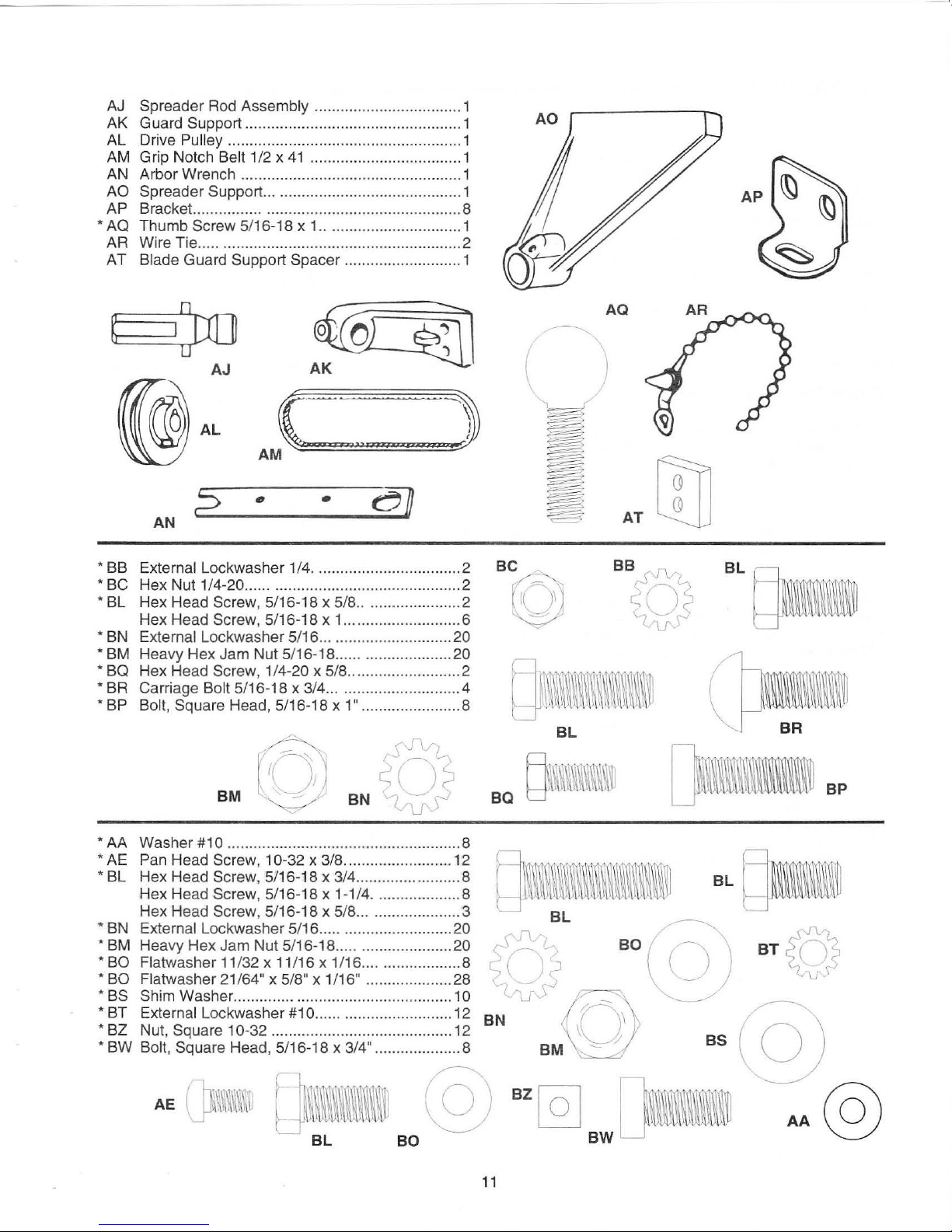
AJ Spreader Rod Assembly ..................
AK Guard Support ..........................
AL Drive
AM Grip Notch
AN Arbor Wrench ......
AO Spreader Support ....................................
AP Bracket. ............... ............................................. 8
* AQ Thumb Screw 5/16-18 x 1 ............
AR Wire Tie ..
AT
Pulley ............................................
Belt 1/2 x
..
......................................................
Blade Guard Support Spacer ........................... 1
41
................................... 1
......
.....................................
................ 1
..
...................... 1
...
....... 1
...
...... 1
..........
..........
..
1
1
..
2
AQ
~
AJ
(@AL
AM
•
AN
*
BB
External Lockwasher 1/4 ........
*
BC
Hex Nut 1/4-20 ...... ........................................... 2
*
BL
He
x Head Screw, 5/16-18 x 5/8
Hex Head
*
BN
External Lockwasher 5/16 ...........................
* BM Heavy Hex Jam Nut 5/16-18 ...... .................... 20
* BQ Hex Head Screw, 1/4-20 x 5/8 .......................... 2
* BR Carriage Bolt 5/16-18 x 3/4 .............. .........
* BP Bolt, Square Head, 5/16-18 x
Screw, 5/16-18 x 1 ...................
~-~
AK
(
.:
'"
eJJ
.:
.:.
:=)
•
...........
1"
....
........... 2
...
....
................ 2
......
...
...
...
....................... 8
.. 6
20
.4
r()l
BM
l~
\
rrn
AT
LzlJ
BL
()IIm
Q\,11~~\\l\11
BL
* AA Washer
* AE Pan Head Screw, 10-32 x 3/8 ....
* BL Hex Head Screw, 5/16-18 x 3/4 ......................
Hex Head
Hex Head Screw, 5/16-18 x 5/8 ....................... 3
* BN E
* BM Heavy Hex Jam Nut 5/16-18 .................
* BO Flatwasher
*
*
* BT External Lockwasher
* BZ Nut, Squa
* BW Bolt, Square Head , 5/16-18 x 3/4" .
xt
BO
Flatwasher
BS
Shim Washer
#1
0 .......................
Screw, 5/16-18 x
ernal Lockwasher 5/16 .............................. 20
11
/32 x 11/16 x 1 /16 ...................... 8
21 /64"
re
x 5/
8"
x 1 /16" .................... 28
.......
........................................... 10
#1
0 ...... ......................... 12
10-32 ........
...
............................... 12
...
.........
1-1
.......
..
.................
/4
...
................. 8
..
................. 8
............ 8
..
12
..
......
... 20
8
11
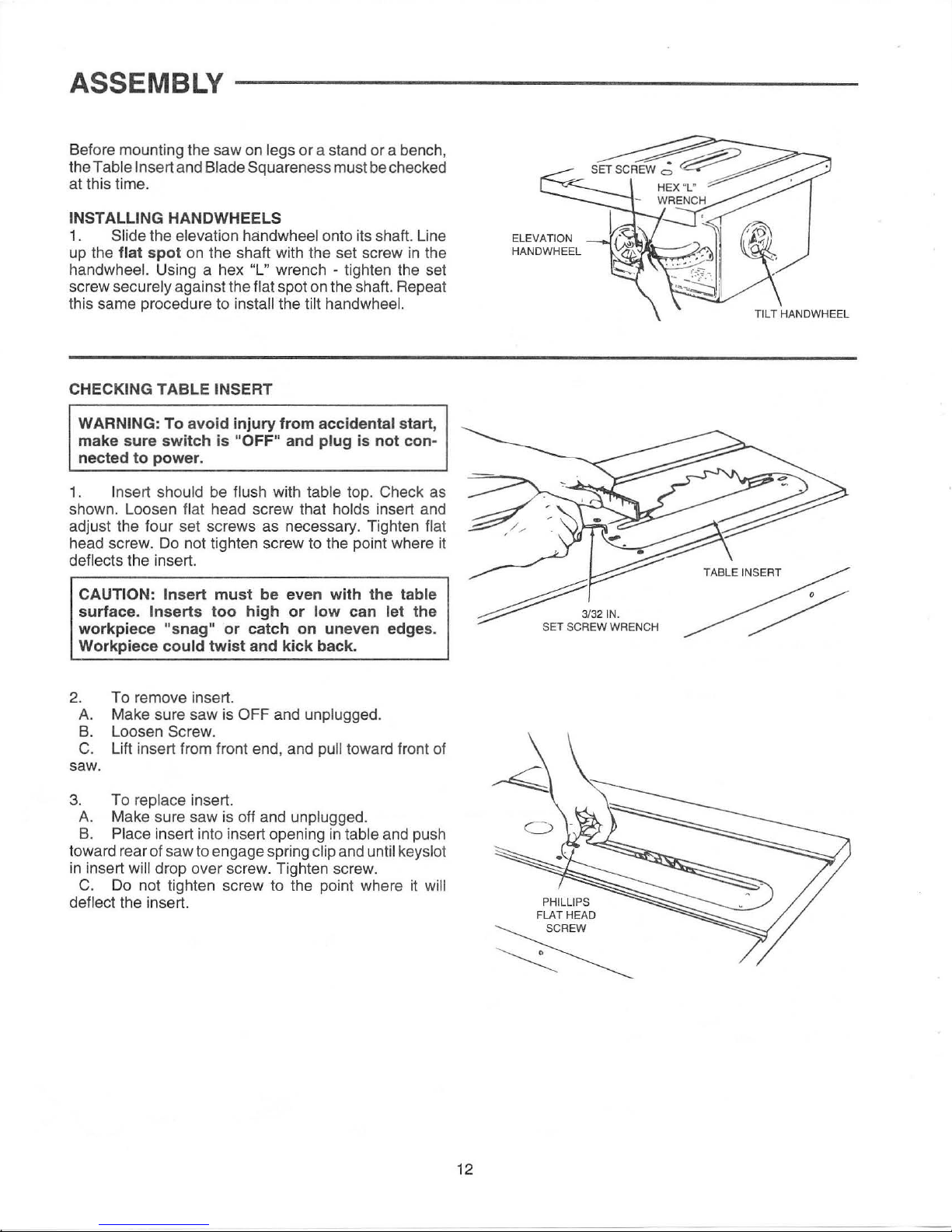
ASSEMBLY
Before mounting the saw on legs
Table Insert and Blade Squareness must be checked
the
at this time.
INSTALLING HANDWHEELS
1.
Slide the elevation handwheel onto its shaft. Line
up the
handwheel. Using a hex "L" wrench - tighten the set
screw
this same procedure to
CHECKING
1.
shown. Loosen
adjust the four set screws as necessary. Tighten
head screw.
deflects the insert.
flat spot
securely against the flat spot on the shaft. Repeat
WARNING:
make sure switch is
nected to power.
Insert should be flush with table top. Check as
CAUTION: Insert must be even with the table
surface. Inserts too high or low can let the
workpiece
Workpiece
on
the shaft with the set screw
install the tilt handwheel.
TABLE INSERT
To avoid injury from accidental start,
"OFF" and plug is not con-
flat head screw that holds insert and
Do
not tighten screw to the point where it
"snag" or catch on uneven edges.
could twist and kick back.
or
a stand or a bench,
in
the
flat
ELEVATION
HANDWHEEL
2. To remove insert.
A.
Make sure saw is OFF and unplugged.
B.
Loosen Screw.
C. Lift insert from front end, and pull toward front of
saw.
3.
To replace insert.
A.
Make sure saw is off and unplugged.
B.
Place insert into insert opening
toward rear of saw to engage spring
in
insert will drop over screw. Tighten screw.
C.
Do
not tighten screw to the point where it will
deflect
the insert.
in
table and push
clip and until keys lot
~
~
PHILLIPS
FLAT HEAD
REW
~
12
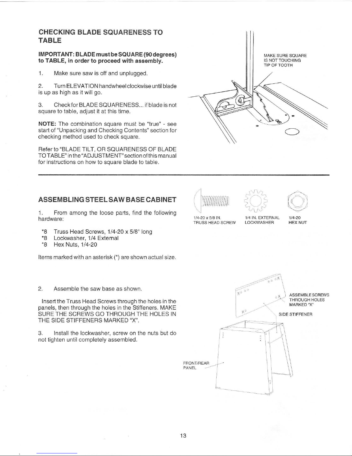
CHECKING BLADE SQUARENESS TO
TABLE
IMPORTANT: BLADEmustbeSQUARE(90degrees)
to TABLE,
in
order to proceed with assembly.
1.
Make sure saw is off and unplugged.
2.
Turn ELEVATI
ON
handwheel clockwise until blade
is
up
as high as it will
go.
3.
Check for BLADE SQUARENESS ... if blade is not
square to
table, adjust it at this time.
NOTE: The combination square must be "t
rue
" - see
start of
"Unpacki
ng
and Checking Contents" section for
checking method used to check square.
Refer to
"BLADE TILT, OR SQUARENESS OF BLADE
TOTABLE"
inthe"
ADJUSTMENT"sectionofthismanual
for instructions
on
how to square blade to table.
ASSEMBLING STEEL
SAW
BASE CABINET
1. From among the loose parts, find the following
hardware:
*8
Truss Head Screws, 1/4-20 x 5/8" long
*8
Lockwasher, 1/4 External
*8
Hex Nuts, 1/4-20
Items
marked wi
th
an
asterisk(*) are shown actual size.
2.
Assemble the saw base as shown.
Insert the Truss Head Screws through the holes
in
the
panels, then through the holes
in
the Stiffeners. MAKE
SURE THE SCREWS GO THROUGH THE HOLES
IN
THE SIDE STIFFENERS MARKED "X".
3.
In
stall the lockwasher, screw on the nuts but do
not tighten
unt
il
completely assembled.
(]l•m~
1/4·
20
x 5
/8
IN.
TRUSS
HEAD SCREW
MAKE SURE SQUARE
IS
NO
T TOUCHI
NG
TI
P OF TOOTH
r\'J~
~
1
/4
IN. EXTERNAL
LOCKWASHER
©
1/4-20
HEX NUT
ASSEMBLE SCREWS
THROUGH HOLES
MARKED "X"
SIDE STIFFENER
.
.
FRONT/REA1 ·
PANEL
..,____
.
~
-·(
13
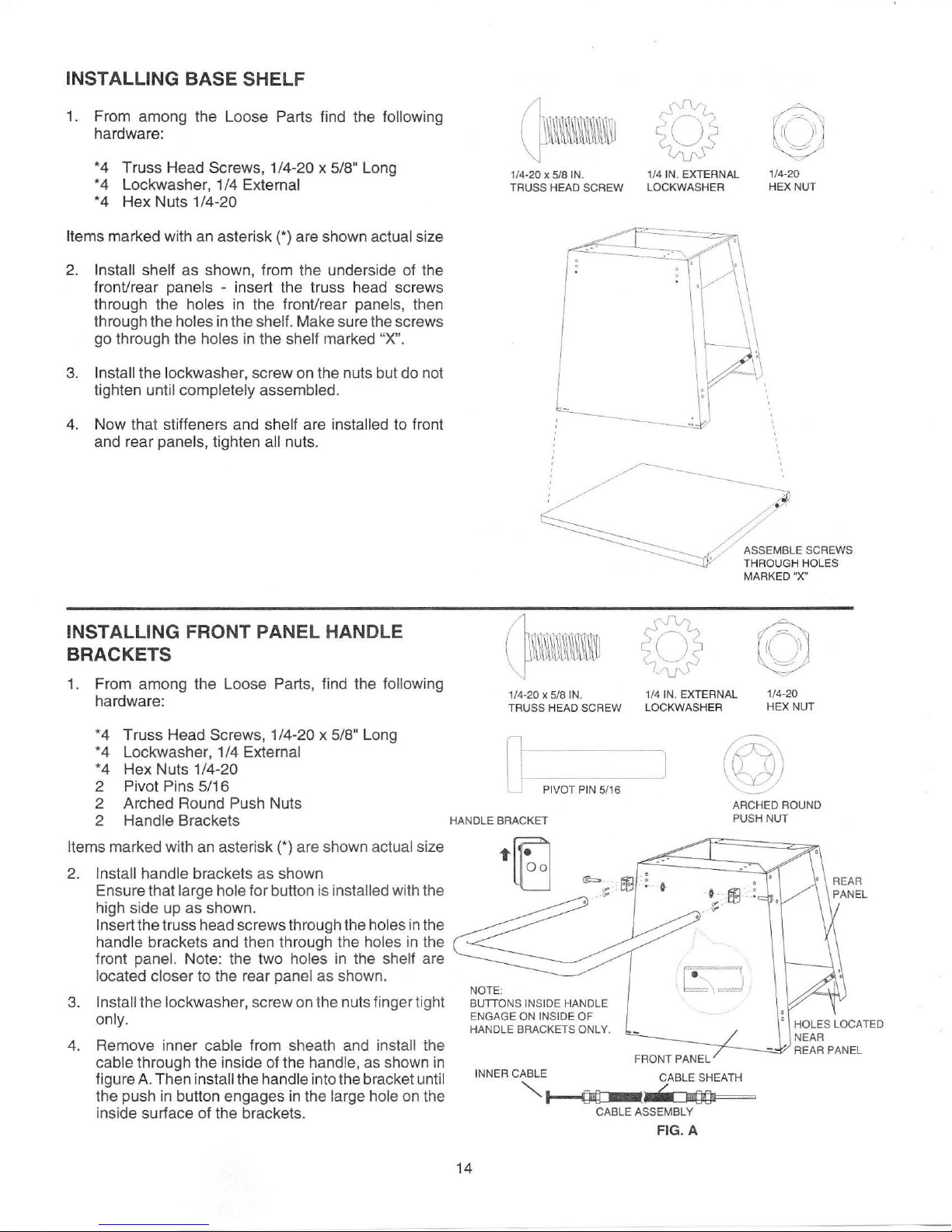
INSTALLING BASE SHELF
1. From among the Loose Parts find the following
hardware:
*4 Truss Head Screws,
*4 Lockwasher, 1/4
*4 Hex Nuts 1/4-20
marked with an asterisk (*)are shown actual size
Items
Install shelf as shown, from the underside of the
2.
front/rear
through the
through the
go through the
3. Install the lockwasher, screw on the nuts but do not
tighten
4.
Now that stiffeners and shelf are installed to front
and rear
panels - insert the truss head screws
holes
holes
in
holes
until completely assembled.
panels, tighten all nuts.
1/4-20 x 5/8" Long
External
in
the front/rear panels, then
the shelf. Make sure the screws
in
the shelf marked "X".
/1
@
~--
1/
4-20 x 5/8
TRUSS
IN
.
HEAD SCREW
1/4 IN. EXTERNAL
LOCKWASHER
/
~)
1/4-2 0
HEX NUT
/
INSTALLING FRONT PANEL HANDLE
BRACKETS
1. From among the Loose Parts, find the following
hardware:
*4 Truss Head Screws ,
*4 Lockwasher, 1/4
*4 Hex Nuts 1/4-20
2 Pivot Pins 5/16
2 Arched Round
Handle Brackets
2
Items marked with an asterisk (*) are shown actual size
2.
Install handle brackets as shown
Ensure that
high side up as shown.
In
sert the truss head screws through the holes in the
handle brackets and then through the holes in the
front
located closer
In
sta
3.
4.
ll
on
ly.
Remove inner cable from sheath and install the
cable through the inside of the handle, as shown
figure
the push
inside surface of the
large hole for button is installed with the
panel. Note: the two holes in the shelf are
to
the rear panel as shown.
the lockwasher, screw on the nuts fing
A.
Then insta
in
button engages
1/4-20 x 5/8" Long
External
Push Nuts
er
tight
ll
the handle into the bracket until
in
the large hole on the
br
ackets.
in
1
/4·20 x SIS
TRUSS HEAD SCREW
Q PIVOT PIN-5-/1-6
HANDLE BRACKET
...
~
lLJ
NOTE:
BUTTONS
EN
HANDLE BRACKETS ONL
INNER
INSIDE
GAGE
ON
INSIDE OF
CABLE CABLE SHEATH
"""~
/ ASSEMBLE SCREWS
,;
THROUGH HOLES
MARKED "X"
IN. 1/4 IN. EXTERNAL 1/4-20
HANDLE
CABLE ASSEMBLY
--
Y.
LO
CKWASHER HEX NUT
J
ARCHED
PUSH
FRONT PANEL
< ::J"(}Qi
FIG. A
NUT
ROUND
14

5.
Swing the handle upwards, until the smaller rear
hole
in
the bracket lines up with the hole
handle.
outside of the bracket.
Slide the 5/16" pivot pin through from the
in
the
SAW BASE
6. After both pivot pins are
Push Nuts on the pivot pins. Note both Push Nuts
will be on the inner surface of the bracket. Place the
Push Nuts on the pivot pins. Block the head of the
pivot pin and tap the
7.
Push
in
the lock buttons and lower handle to ensure
Push Nuts are properly engaged.
8.
Tighten nuts at brackets, to front panel.
WARNING: Never operate saw when handle is in
the raised position. Handle is f
and must
operation is perform
be
in the lowered position before any
installed, install the Arched
Push Nut on with a 7/16" socket.
or
moving saw only
ed
on the saw,
of
any kind.
INSTALLING FRONT PANEL LEVELLERS
1.
From among the Loose Parts, find the following
hardware:
4 Hex Nuts 3/8-16
2 Levelling Feet
2 Leveller
Plates
3/8·16
HEX NUT
L . \ J
,
1f~~
HEAD OF HEAD OF
PIVOT PIN
l LOCK PIVOT PIN
'j
J:tf\
'
BUTTON
s~
~
LEVELLER
PLATE
2. Insert leveller plate into bottom corners of front
panel. Ensure that lip on leveller plate faces
plate is too tight for a push fit, tap lightly with a
hammer on the flange of the
tabs extend through the slots of the front pane
3.
Screw on a hex nut to the levelling foot. Turn down
to within a half inch of top of foot to provide enough
in
an
room to fit
4.
Insert foot with nut installed thru underside of level-
ler
plate.
5.
Add nut to leveller. Screw down to plate. Adjust to
suit floor, when unit is
two wrenches.
open end wrench.
leveller plate, until the
fully assembled, tighten with
up.
l.
If
FRO
NT
PANEL
HEX NUT
PLATE
HEXNUT
~
~m)
r ,
~
:_,
"""\..~~
~~
~
15
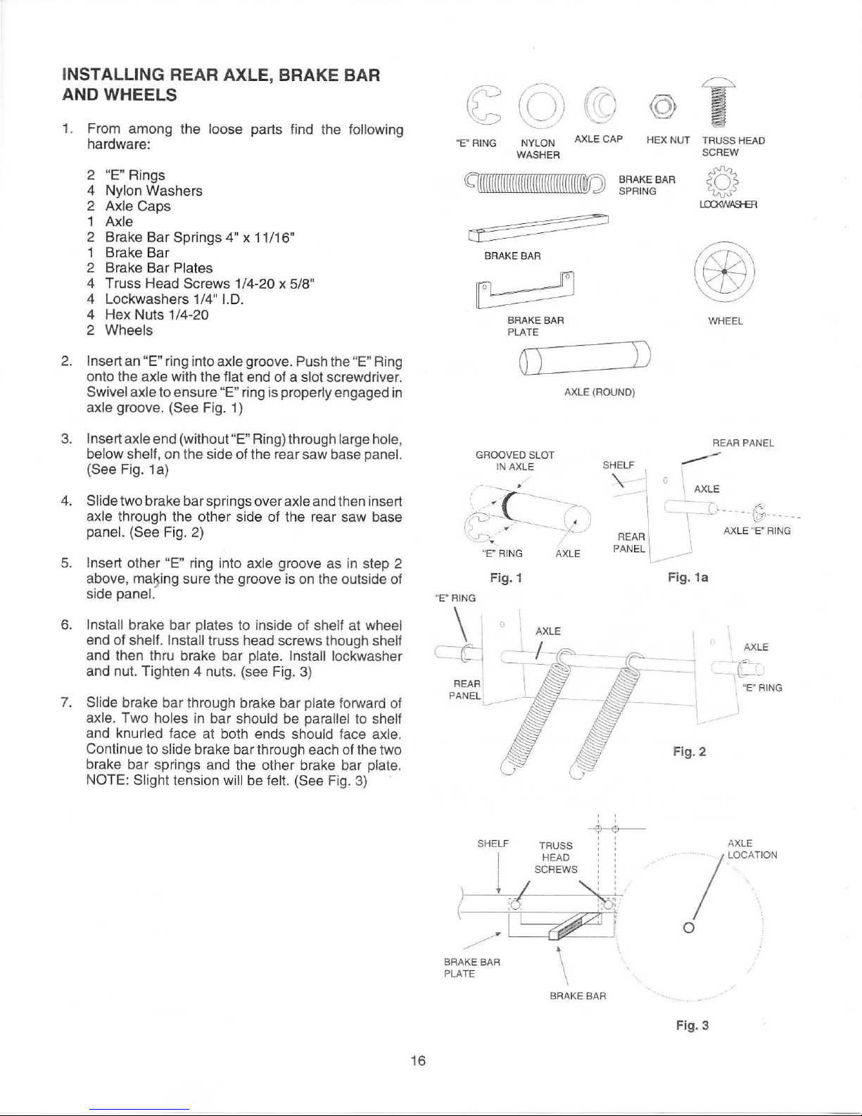
INSTALLING REAR AXLE, BRAKE BAR
AND WHEELS
1. From among the loose parts find the following
hardware:
2
"E" Rings
4
Nylon Washers
2
Axle Caps
1 Axle
2 Brake Bar Springs
4"
x 11/16"
1 Brake Bar
2 Brake Bar
Plates
4 Truss Head Screws 1/4-20 x 5/8"
4 Lockwashers 1/4"
1.0.
4 Hex Nuts 1/4-20
2 Wheels
2. Insert an "E" ring into axle groove. Push the "E" Ring
onto the
axle with the flat end of a slot screwdriver.
Swivel axle to ensure "E" ring is properly engaged
in
axle groove. (See Fig. 1)
3.
Insert axle end (without "E" Ring) through large hole,
below shelf,
on the side of the rear saw base panel.
(See Fig. 1
a)
4.
Slide two brake bar springs over axle and then insert
axle through the other side of the rear saw base
panel. (See Fig. 2)
5.
Insert other "E" ring into axle groove as
in
step 2
above,
ma~ing
sure the groove is
on
the outside of
side
panel.·
6.
Install brake bar plates to inside of shelf at wheel
end of shelf. Install truss head screws though shelf
and then thru brake bar plate. Install lockwasher
and nut. Tighten 4 nuts. (see Fig.
3)
7.
Slide brake bar through brake bar plate forward of
axle. Two holes
in
bar should be parallel to shelf
and knurled face at both ends should face axle.
Continue to slide brake bar through each of the two
brake bar springs and the other brake bar
plate.
NOTE: Slight
tension will be felt. (See Fig.
3)
16
~
©
(((J
@
f
"E" RING NYLON
AXLE CAP
HEX NUT
TRUSS HEAD
WASHER
SCREW
CC(
(((
(((
(((((((((((((((((((((((((((((WJ
@
BRAKE
BAR
SPRING
u::x:»VASHER
~
~
BRAKE BAR
~
BRAKE BAR
WHEEL
PLATE
[)
D
AXLE (ROUND)
REAR PANEL
SHELF
---
GROOVED S
LOT
IN AXLE
'\
I o
I
1
'. AXLE
I
I
\
- -
I:}-
- - -
-~--
----
\
AX
LE
..
~-,
RING
p~
~~~
_J
"E" RING AXLE
"E" RING
REAR'
PANEL
Fig. 1
~--
AXLE
'
e e
'
SHELF TRUSS '
j
HEAD
SC
REWS
~
~
~
BRAKE BAR
PLATE
BRAKE BAR
L -
__.
Fig. 1a
AXLE
"E" RING
AX
LE
/LOC
ATI
ON
0
Fig. 3

8. Position brake bar so an equal amount of each end
extends past bottom shelf and position the springs
between the holes in the brake bar and bottom shelf
outer edge.
9.
Install two nylon washers over axle.
10. With saw base secure so it won't slide, pull the brake
bar back enough to slide wheel onto axle. Release
brake bar.
washers.
11.
Install axle cap over end of axle to secure wheel. Tap
in place with hammer
gaged.
12. Repeat steps 9 -
NOTE: Hub of wheel goes against nylon
to
ensure cap is tightly en-
11
for opposite side.
WHEEL HUB
AGAINST
NY
LO
N WASHER
....
...
....
................
AXLE
HUB
/
~WHEEL
WHEEL -
CABLE
VIEW FRO
STOP _
-
SPRING
-
AXLE
M UNDERSIDE
SHELF
cr
OF
I
I
I
-
I
:>
J
AXLE CAP
-
-co
-
ASSEMBLING
1.
From among the loose parts find the following
hardware:
D Truss Head Screw
E Lockwasher 1/4"
F Hex Nuts
G Cable Spring 2
H Brake
I Bottom Shelf Fitting ..................................... 2
SAW
BASE
1/
4-20
1/4
Cable Sheath .................................... 2
BRAKE
1/4-20 x 5/8" .
1.0
.................................... 2
...... .................................... 2
x 5/8" ............................ 1
SYSTEM
..
......
J Brake Bar Cable Stop ................................. 2
2.
Install 1/2" spacer blocks (not included) between
the brake bar and the wheel to keep tension on
the springs.
Install bottom shelf fittings (2) with 1/4-20 x 5/8" truss
3.
head screws from underside of base shelf as show
Face of fitting with 5/16" dia. hole should face toward
panel. Secure in place with an external
front
lockwasher and
1/4-
20
hex nut.
...
..... 2
n.
D E F
Quam
G c
J
SHELF : BETWEEN BRAKE
@ ©
!llllllllllllllllllllllltlllllllli
@l
--<~~
:'
OJ
~
'
• INSTALL 112·
eer---
': , ON
.. (NOT
l
(~
BRAKEBAR
PLATE
y
~
!
-
BRAKE BAR
I
SPACER BLOCK
BARANDWH
EACH SIDE'
EEL
INCLUDED) -- _
--
17
NUT
\~
u
TRUSS
/
HEAD SCREW WITH 5/16. HOLE
LOCKWASHER
~SHELF
BO
TTOM SI
FITTING
FACING FRONT
DE
OF SHELF
FRONT
PANEL E
(t-c====~
ND
o
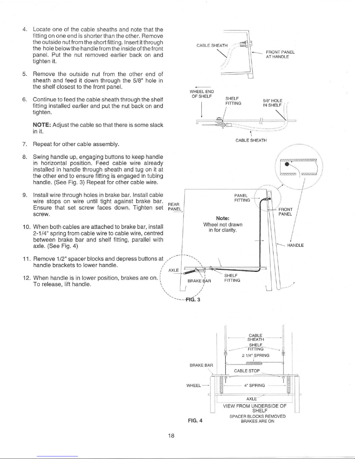
4.
Locate one of the cable sheaths and note that the
fitting on one end is shorter than the other. Remove
the outside nut from the short fitting.
the
hole below the handle from the inside of the front
Insert it through
panel. Put the nut removed earlier back on and
tighten
5.
Remove the outside nut from the other end of
sheath and feed it down through the
it.
5/8" hole
the shelf closest to the front panel.
6.
Continue to feed the cable sheath through the shelf
fitting installed earlier and put the nut back on and
tighten.
in
CABLE SHEATH
WHEEL END
OF SHELF
""'';.'
.
/'/
'
FRONT PANEL
AT HANDLE
HOLE
5/8'
IN
SHELF f
NOTE:
in
7.
Repeat for other cable assembly.
8.
Swing handle up, engaging buttons to keep handle
in
installed
the other end to ensure fitting is engaged
handle. (See Fig.
Install wire through holes in brake bar. Install cable
9.
Adjust the cable so that there is some slack
it.
horizontal position. Feed cable wire already
in
handle through sheath and tug on it
in
tubing
3)
Repeat for other cable wire.
at
wire stops on wire until tight against brake bar.
Ensure that set screw faces down. Tighten set
screw.
10. When both cables are attached to brake bar, install
2-1
/4" spring from cable wire to cable wire, centred
between brake bar and
shelf fitting, parallel with
axle. (See Fig. 4)
11. Remove 1/2" spacer blocks and depress buttons at
handle brackets
12. When handle is
to
lower handle.
in
lower position, brakes are on. i -
To release, lift handle.
---
.-
REAR
PANEL
--
--
/-
,/
AXLE~
\\
' /
'--
....
--,,
u
....
;;;
..
-a-
lJ
BRAK~rR
----FIG: 3
--
--
Note:
Wheel not drawn
in for clarity.
\
~'~,
F~
~::::::;:;:::::::::::::::::;::;J
\ :
...._______
SH
FITIING
CABLE SHEATH
---+--··-.""'"··.,
PANEL ( ..-I
FITTING T ,_ - 1
··
..
--
.
~
.
ELF
··
.......
..
5l
..
u
L
.....
n ·
1.
...
..
__
.....
--
/'·
...
..
..
\
1
~-···
FRONT
PANEL
-....__
HANDLE
U------'
····
..
..-··
18
BRAKE
WHEEL-
FIG. 4
BA
( ,
-_
I 2 1/4' SPRING @
-
R
;-..
'--+--
'-
If
~-
I
VIEW FROM UNDERSIDE
L
SPAC
SHEATH - -
_____
CABLE STOP
4' SPRING
AXLE
ER
BLOCKS REMOVED
BRAKES
~~'
SHELF
FITTIN
I
SHELF
G-
-
-·
ARE
~
~
T
- - -
OF
ON
p
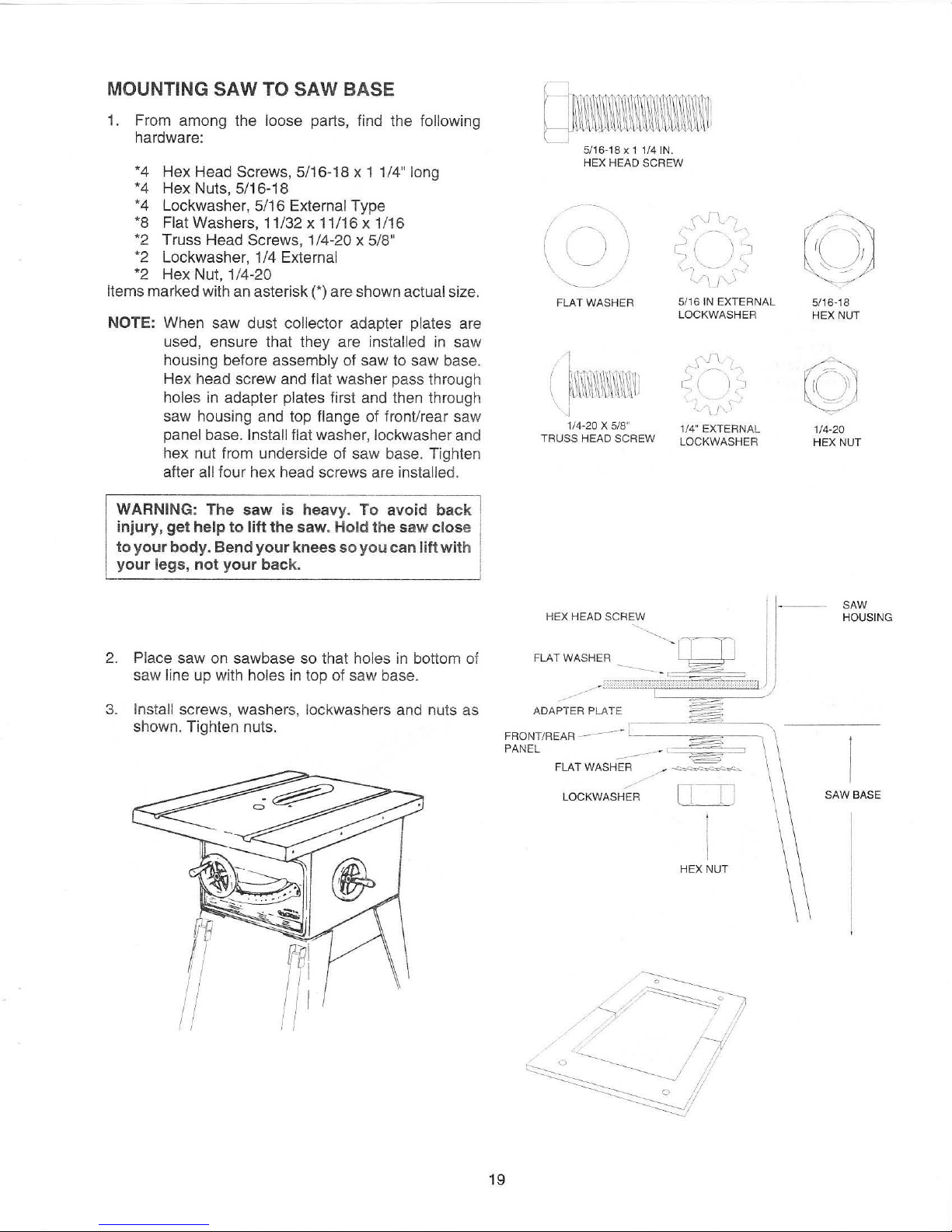
MOUNTING
SAW
TO
SAW BASE
1.
From among the loose parts, find the following
hardware:
*4 Hex Head Screws, 5/16-18 x 1 1/4" long
*4
Hex Nuts, 5/16-18
*4 Lockwasher, 5/16
External Type
*8
Flat Washers, 11/32 x 11/16 x 1/16
*2
Truss Head Screws, 1/4-20 x 5/8"
*2
Lockwasher, 1/4 External
*2
Hex Nut, 1/4-20
Items
marked with an asterisk (*) are shown actual size.
NOTE: When saw dust collector adapter plates are
used, ensure that they are
installed
in
saw
housing before
assembly of saw to saw base.
Hex head screw and
flat washer pass through
holes
in
adapter plates first and then through
saw housing and top
flange of front/rear saw
panel base. Install flat washer, lockwasher and
hex nut from underside of saw base. Tighten
after
all four hex head screws are installed.
WARNING: The saw is heavy. To avoid back
injury, get help to lift the saw. Hold the saw close
to your body. Bend your knees so you can lift with
your legs, not your back.
2.
Place saw on sawbase so that holes
in
bottom of
saw
line up with holes
in
top of saw base.
3.
Install screws, washers, lockwashers and nuts as
shown. Tighten nuts.
19
QDBmm~~
5/
16-1
8X11/41N.
HEX HEAD
SCREW
f
~~
\
('0lj
--
~
·~\
(U)
[~
( )
~
'
/'
'\-~,
.__
' >
~
/
V\j)
FLAT WASHER
5/
16
IN
EXTERNAL
LOCKWASHER
I
,S'!_:
l,
(
f\~m\~~)\~~Wil
~~
)
~J
j
i>\r,\-
1/4-20 X 5/8"
1/4" EXTERNAL
TRUSS HEAD SCREW
LOCKWASHER
FRONT/REAR
--
-~----==""?'
-~
PANEL
--
-=~~=
FLAT WASHER
/
/
LOCKWASHER
ll
J J
HEX NUT
CQJ
5/16 -18
HEX
NUT
©
1/4-20
HEX
NUT
SAW
HOUSING
SAW BASE
IN
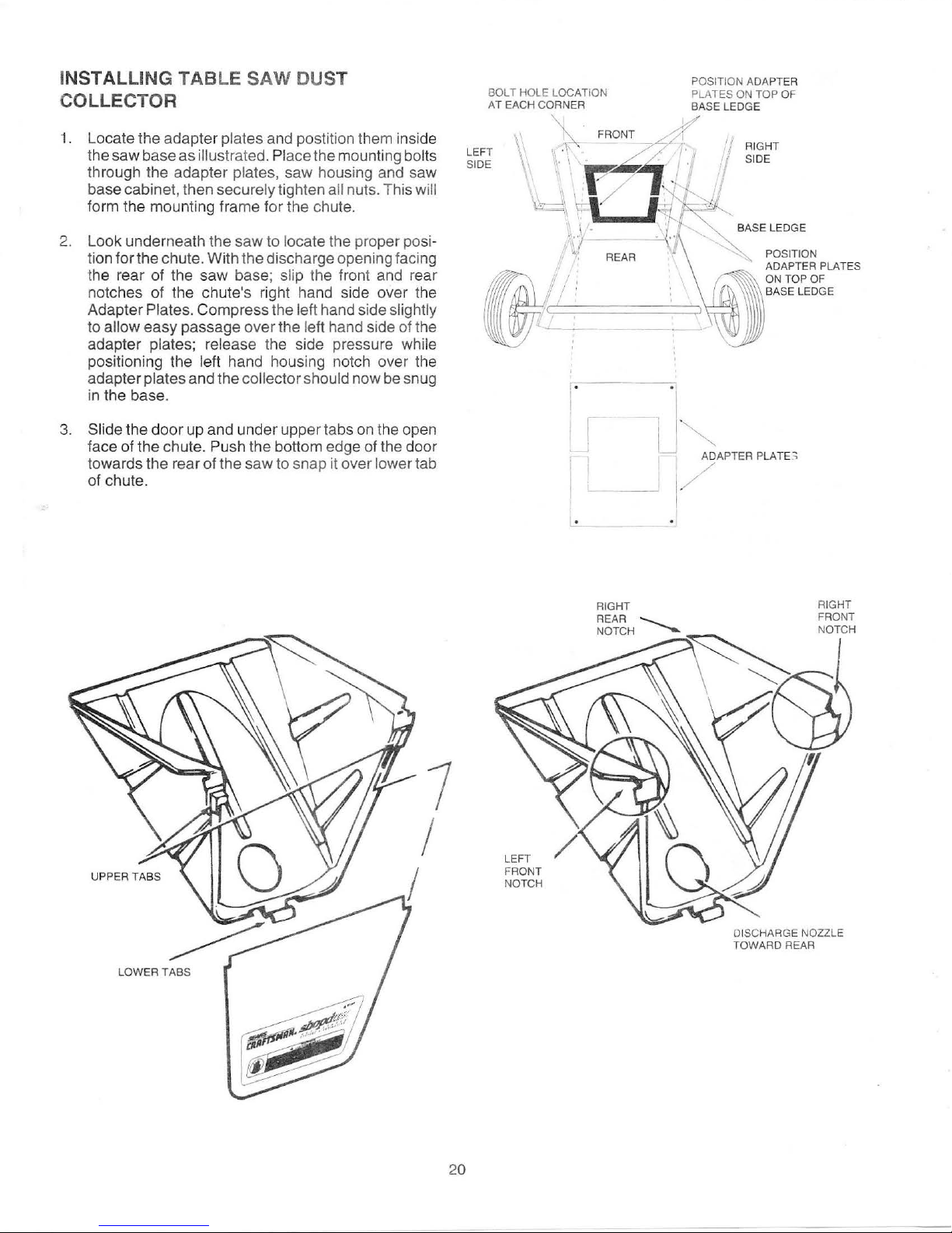
STALLING TABLE SAW DUST
COLLECTOR
1.
Locate the adapter plates and postition them inside
the saw base as
through the adapter plates, saw housing and saw
base cabinet, then
form the mounting frame for the chute.
illustrated. Place the mounting bolts
securely tighten all nuts. This will
BOLT HOLE LOCATION
AT EACH CORNER
LEFT
SIDE
1
'
RIGHT
SIDE
2. Look underneath the saw to
tion for the chute. With the discharge open ing facing
the rear of the saw base;
notches of the chute's right hand side over the
Adapter
to allow easy passage
adapter
positioning the left hand housing notch over the
adapter
in the base.
3.
Slide the door up and under upper tabs
face of the chute.
towards the
of chute.
Plates. Compress the left hand side slightly
plates; release the side pressure while
plates and the collector should now
Push the bottom edge of the door
re
ar
of the saw to snap it over lower tab
locate the proper posi-
slip the front and rear
over
the left hand side of the
on
be
snug
the open
i•
II
' - J
r
1/
ADAPTER
/
POSITION
ADAPTER PLATES
ON TOP OF
LEDGE
BASE
PLATE~
RIGHT
FRONT
NOTCH
LOW
ER
TABS
7
I
I
20
LEFT
FRONT
NOTCH
DISCHARGE NOZZLE
TOWAR D
REAR
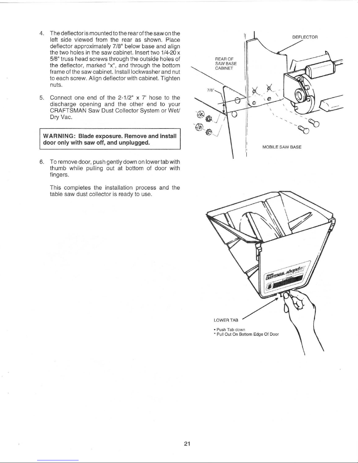
4. The deflector is mounted to the rear of the saw on the
left side viewed from the rear as shown. Place
deflector
the two holes
5/8" truss head screws through th e outside holes of
the
frame of the saw cabinet.
to each screw.
approximately 7/8" below base and align
in
the saw cabinet. Inse
rt
two 1/4
-20
deflector, marked "x", and through the bottom
lnstalllockwasher and nut
Align deflector with cabinet. Tighten
nuts.
x
~INET
REAR OF
SAW
BASE
DEFLECTOR
5. Connect one end of the
discharge opening and the ot
CRAFTSMAN
Saw Dust Collector System or Wet/
2-1
/2" x 7' hose to the
her
end to your
Dry Vac.
WARNING:
Blade exposure. Remove and install
door only with saw off , and unplugged.
6.
To remove door, push gently down on lower tab with
thumb
while pulling out
at
bottom of doo r with
fingers.
completes the installation process and the
This
table saw dust collector is ready to use.
MOBILE
SAW
BASE
21
LOWER TAB
• Push Tab
• Pu
ll
Out
On Bottom Edge
down
Of
Door
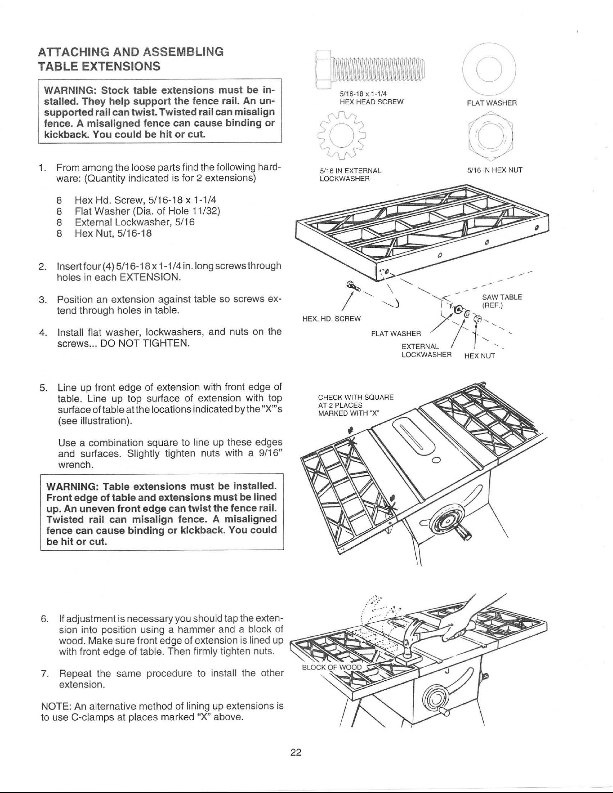
ATTACHING AND ASSEMBLING
TABLE EXTENSIONS
WARNING: Stock table extensions must be installed.
supported rail can twist. Twisted rail can misalign
fence. A misaligned fence can cause binding or
kickback. You
They help support the fence rail.
could be hit or cut.
An
un-
/-
(cJ)
FLAT WASHER
1. From among the loose parts find the following hardware: (Quantity indicated is for 2 extensions)
8 Hex Hd. Screw, 5/16-18 x 1-1/4
8 Flat Washer (Dia. of Hole 11/32}
8 External Lockwasher, 5/16
8 Hex Nut, 5/16-18
2.
lnsertfour(4) 5/16-18 x 1-1/4 in.long screws through
holes
in
each EXTENSION.
3.
Position an extension against table so screws ex-
tend through holes
4.
Install flat washer, lockwashers, and nuts
screws ...
5.
Line
table. Line up top surface of extension with t
surface of table at the locations indicated by the "X"'s
(see illustration).
Use a combination square to line
and surfaces. Slightly tighten nuts with a 9/16"
wrench.
DO
up
front edge of extension with front edge of
in
table.
NOT TIGHTEN.
up
these edges
on
the
op
5/16
IN
EXTERNAL
LOCKWASHER
' \
I
HEX. HD. SCREW
CHECK WITH SQUA
AT 2 PLACES
MARKED
WITH "X"
·:~
'-....
---.........
) I
FLATWASHER
RE
IN
5/16
..........
..........
"-..,<_
'
(.€~
y (if'
/7
EXTERNAL
LOCKWASHER HEX NUT
--
-
SAW TABLE
(REF.)
c:
-...
' • '--....
HEX NUT
....
.._
'.
WARNING: Table extensions must be installed.
Front edge of table and extensions must be lined
up. An uneven front edge can twist the fence rail.
Twisted rail can misalign fence. A misaligned
fence can cause binding
be hit or cut.
7.
Repeat the sa
extension.
NOTE:
to use C-clamps at places marked
An
alternative method of lining up extensions is
me
or
kickback. You could
procedure to insta
"X" above.
ll
the other
22

INSTALLING TABLE EXTENSION
BRACKETS
1.
From among the loose parts find the following hardware:
4
Hex Head Screws , 5/16-18 x
1" long
4
External Lockwashers, 5/16-18
4
Flatwashers, 21/64" inside dia.
4
Hex Nuts, 5/16-18
4
Brackets
2.
Put one of the brackets against the right edge of the
right extension so the bracket is
lined up with the
FIRST hole near the front of the extension. Insert a
1 inch
long screw through a flat washer, through top
hole in the bracket, and through the FIRST hole
in
the extension. Install a lockwasher and nut
on
the
screw. Leave the nut
loose enough so you can
adjust this bracket
later.
3.
Install another bracket against the left side of left
extension using the same procedure explained
above.
4.
Put one of the brackets against the right rear edge
of the right extension so the bracket is
lined up with
the
FOURTH hole near the rear of the extension
(see illustration).
5.
Insert one of the 1 inch long screws through a flat
washer, through the bracket, and through the
FOURTH hole
in
the extension. Install a lockwasher
and nut on the screw. Tighten the nut only slightl
y.
6.
Install the other bracket against the left side of the
left extension using the same procedure explained
above.
7.
Do not tighten the bracket nuts until the front and
rear
rails are
in
place and adjusted properly. See
INSTALLATION PROCEDURE for front and rear
guide bar.
QJ~~~~Wl\\\\~\'1
l (
.,t
..
d
II
d
LJ
11N. HEX HD .
SCREW
(0')
~
21/64 IN WASHER
0
,.
23
\
11
c
(
\
l
~
J r
}
~
I
J
5/16 IN. EXTERNAL
5/161N.
LOCKWASHER
HEX NUT
BRACKET
SCREW
5/16-18 X 1"
REAR
OF
EXTENSION
4TH HOLE
BRA
CKET
WASHER
~
5/16
-18X1
'
HEX HEAD
SCREW
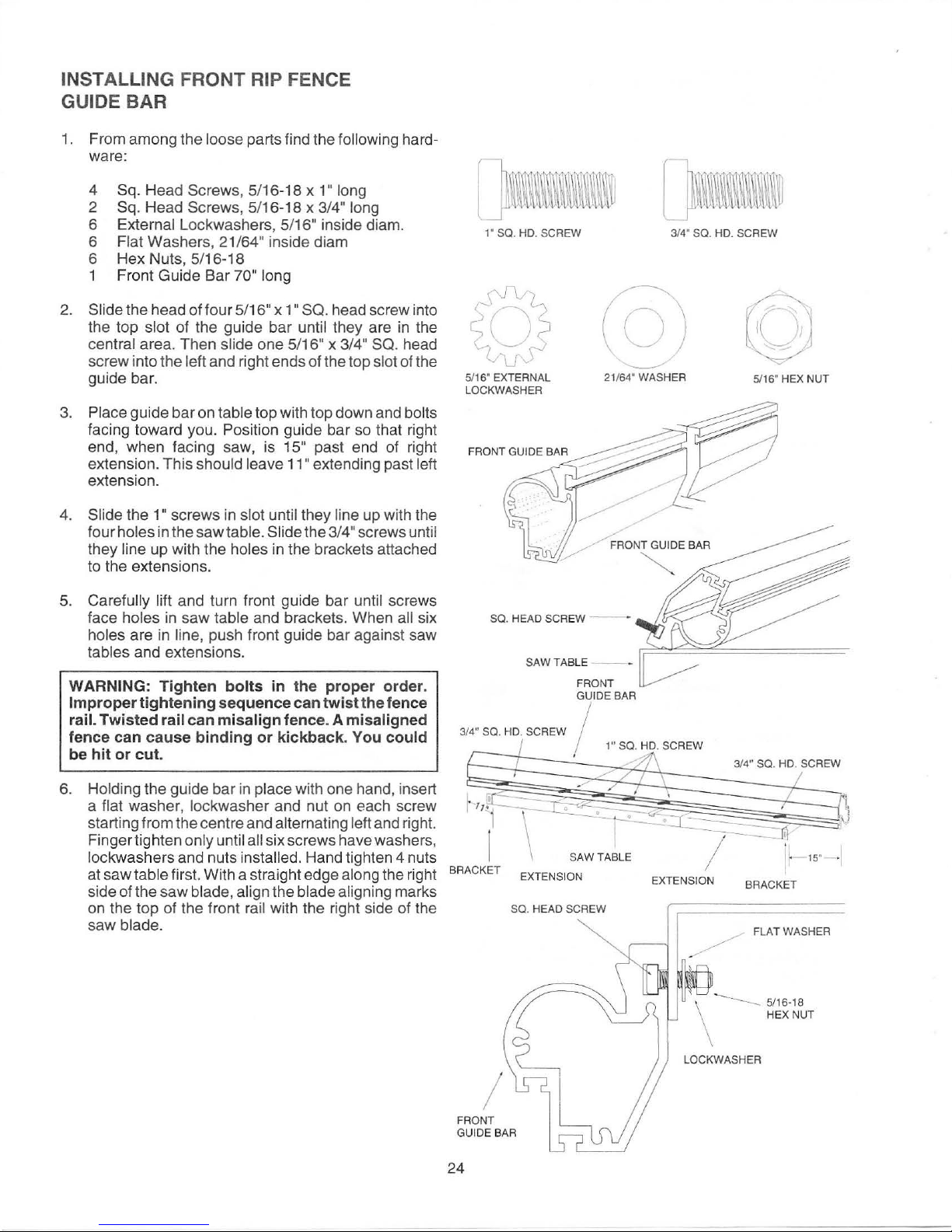
INSTALLING FRONT RIP FENCE
GUIDE BAR
1.
From among the loose parts find the following hard-
ware:
01
4 Sq. Head Screws , 5/16-18 x 1
2 Sq. Head Screws, 5/16-18 x 3/4
6 External Lockwashers, 5/16
Flat Washers , 21/
6
6 Hex Nuts, 5/16-18
1 Front Guide Bar
2.
Slide the head of four 5/16
the top
slot of the guide bar until they are in the
01
64
inside diam
01
70
long
01
x 1
central area. Then slide one 5/16
screw into the
left and right ends of the top slot of the
guide bar.
3.
Place guide bar on table top with top down and bolts
facing toward you. Position guide bar
end, when facing saw, is
extension. This
should leave
15
11
extension.
long
01
long
01
inside diam.
01
SQ.
head screw into
01
01
x 3/4
01
01
so
past end
extending past left
SQ. head
that right
of
right
1'
Sa.
HD. SCREW 3/4'
{QJ
(-v
5/16' EXTERNAL
LOCKWASHER
21
/64' WASHER
Sa.
HD. SCREW
5/16' HEX NUT
holes
01
screws
in
the saw table. Slide the 3/4
in
slot until they line up with the
01
screws until
4.
Slide the 1
four
they line up with the holes in the brackets attached
to the extensions.
5.
Carefully lift and turn front guide bar until screws
face
holes
in
saw table and brackets. When all six
holes are in line, push front guide bar against saw
tables and extensions.
WARNING: Tighten bolts
in
the proper order.
Improper tightening sequence can twist the fence
rail. Twisted rail can misalign fence. A misaligned
fence can cause binding or kickback. You could
be hit or cut.
6.
Holding the guide bar
a
flat washer, lockwasher and nut on each screw
starting from the centre and
Fingertighten
lo
ckwashers and nuts installed. Hand tighten 4 nuts
table first. With a straight edge along the right
at saw
side of the saw
only until all six screws have washers,
blade, align the blade aligning marks
on the top of the front
blade.
saw
in
place with one hand, insert
alternating left and right.
rail with the right side of the
Sa.
HEAD SCREW
SAW TABLE
FRONT
GUIDE
3/4" SQ. HD. SCREW I
BRACKET
EXTENSI
Sa
SAW TABLE
ON
. HEAD SCREW
--
-
--
-
BAR
1" SQ. HD. SCREW
/
EXTENSION
BRACKET
FLAT
WASHER
15
· ·I
FRONT
GUIDE
24
I
BAR
-
-----
LOCKWASHER
5/16·18
HEX NUT
 Loading...