

Page 1
II
fl
srurcoxs
DCATS
rl
De,partment
731.4.
Tbronto
TECHNICAL
FLASH
T.F.
26-23
ApriL
7, 1983
SEF?VICE
INFORMATINN
*^
CGNMPACT
P(}&TAtsLE
I}RYffiffi
c26(}-
6@g(}(}
'.*
Page 2
T.F.
26-23
INDEX
PAGE
I General
. . . .
. . . . . . .
. .
. . .
. .
.
. . ' . . . . .l
II
Specifications...............
.....2
III Basic Operation....o...o..........3
IV
Disassembly.
.
. . . . . . . . . . .
. . . . . . . .
.
.4
V Trouble
Shooting..................18
Page 3
-1-
T.F.
26-23
SERVICE
INSTRUCTIONS
COMPACT
PORTABLE
DRYER
I.
GENERAL
This
is
a
portable
electric
dryer
designed to oPerate
efficiently
on
I20
volts,
60
hertz.
It
is equipped
with a
Ehree-wire
cord
for use
in a
grounded
receptacle.
THE UNTT
MUST BE
GROUNDED!
Although
noE
necessary
for operation,
it
would
be advantageous,
as with
any
dryer,
to
vent
this unit
to
the
outside
whenever
and
wherever
possible for maximum
efficiency.
(See
specification
section).
The
reset
button
must
be
pushed
to re-start
the
dryer
each
time the
door
is opened
and closed.
The rear
panel
must
be rercved
for urost
servicing
except
to re-position
a
displaced
drive
belt,
or
idler
pulley
and
spring.
The
timer
controls
drying time.
Ttte
brown
area
of
the
dial
is
heat,
except
the
last
7 minutes of
the cycle,
which
is a cool-down
period.
The orange
area of
the
dial is air
(no
heat) only.
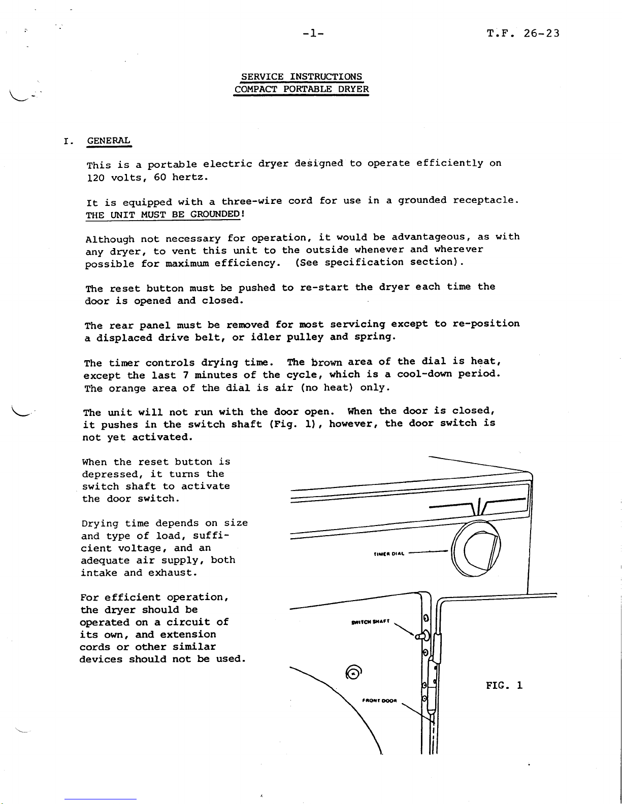
the unit
will not run
with
the
door oPen.
l{hen the
door
is
closed,
it
pushes
in the
switch
shaft
(Pig.
I),
however,
the
door
switch
is
not
yet
activated.
When the reset
button
is
depressed,
it turns
the
switch shaft
to
activate
the door
switch.
Drying tsime
depends on
size
and
type of load,
suffi-
cient
voltage, and
an
adequate
air supply,
both
intake and exhaust.
For
efficient
operation,
the dryer
should be
operated on a circuit
of
its own,
and extension
cords or
other
similar
devices
should
not be used.
Page 4
rr.
SPECIqrgaT-IoNS.
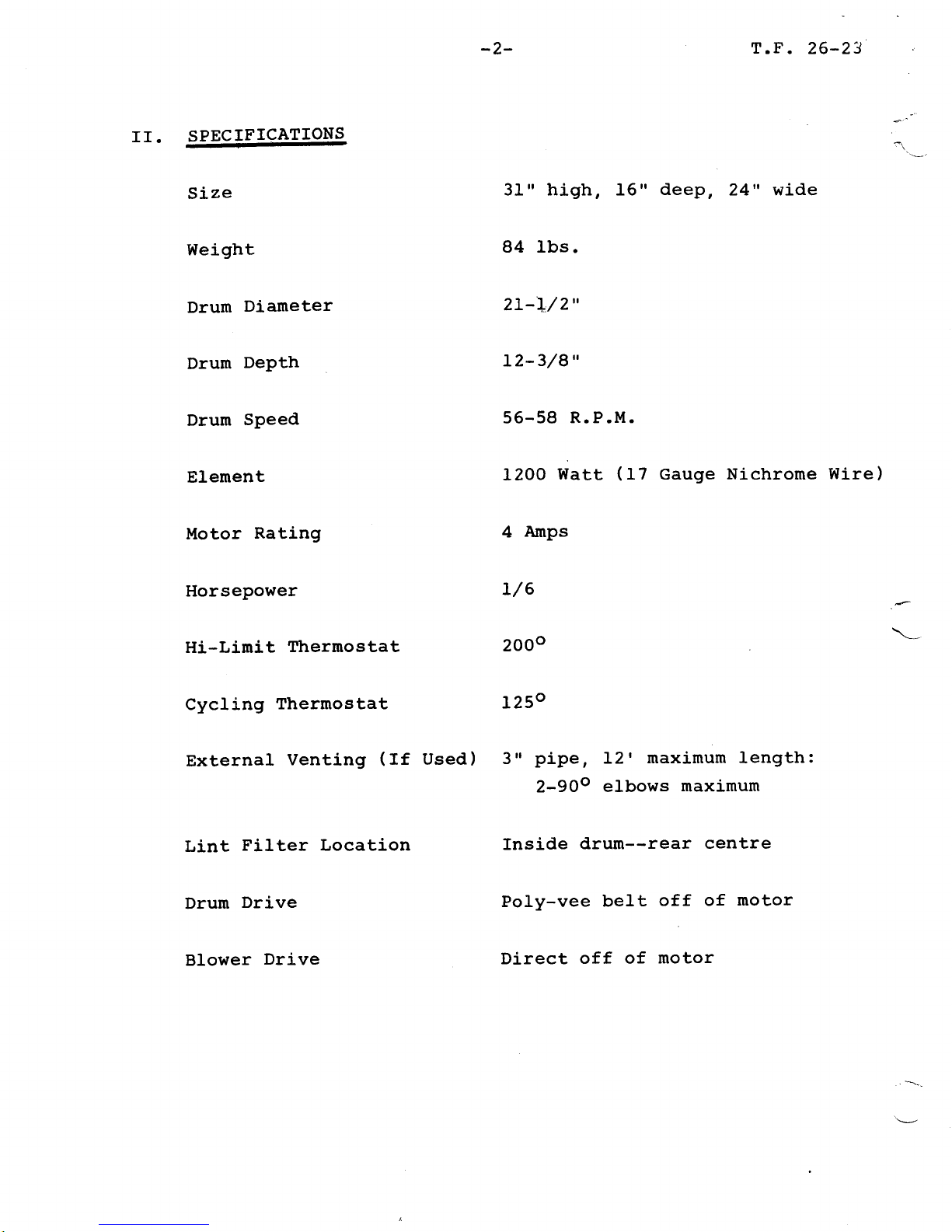
Size
Weight
Drum
Diameter
Drum
DePth
Drum
Speed
Element
Motor
Rating
Drum
Drive
Blower
Drive
-2-
T.F.
26-23
31" high, 16"
deep,
24" wide
84 Ibs.
zL-I/2"
12-3/8"
56-58
R.P.M.
12OO
Watt
(17
Gauge
Nichrome
Wire)
4
Anps
Poly-vee
belt
off of
motor
Direct
off of
motor
Horsepower
I/6
"\--
Hi-Limit
Thermostat
2000
Cycling
Thermostat
L250
External
Venting
(te
Used)
S"
pipe,
12'
maximun length:
2-9Oo
elbows
maximum
Lint
Filter Location
fnside
drum--rear
centre
Page 5
-3-
T.F.
26-23
\
III. BASIC
OPERATTON
CUT.tsffiY
UIEH
(,FHtl(lUER
DffYEN
stx E
stc
g,fttrfis
T}€RilOStAI
lHr
rjflrTl
HE Tilt8
AIHAfi
rpoR
ffilrsrAT
lcofinuj
mr nile
tntfl
l
illsrm
rx,cT
TXHAUST
FIG.
2
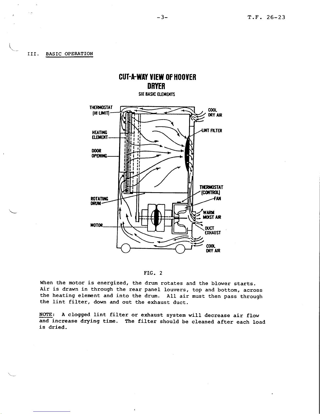
When
the
motor is energized,
the drum
rotaCes
and the blower
starts.
Air is
drawn in
through
the
rear
panel
rouvers,
top
and bottom,
across
the
heating
elerent
and
into
the drum.
All
air must then
pass
through
the
lint filter,
down
and
out
the
exhaust
duct.
NCIE:
A clogged
lint filter
or exhaust
system will
decrease
air flow
and increase
drying
time.
The filter
should
be
cleaned
after
each
load
is
dried.
al
f,
rl
,1,
-\
=-\
7
:?
Page 6
-4-
DISASSEMBLY
BE
SURE
THE
UNIT
IS
UNPLUGGED
A.
Rear
Panel
Assembly
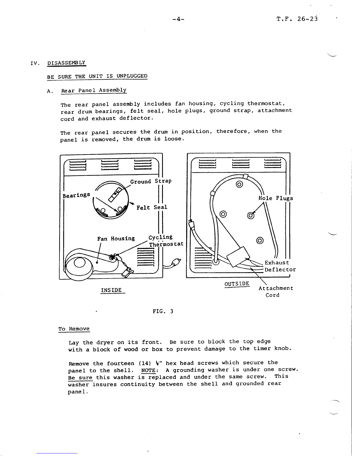
The
rear
panel assembly
includes
fan
housing,
cycling
thermostat,
rear
drum
bearings,
felt
seal, hole
plugs,
ground
strap, attachment
cord
and
exhaust
deflector'
The
rear
panel secures
the drum
in
position,
therefore,
when
the
panel is
removed,
the
drum
is
loose.
Hole Plugs
Exhaus
t
De
f Iec
tor
OUTS
IDE
-
At Eachmen
t
Cord
TNS
IDE
FIG.
3
To
Remove
Lay
the
dryer on
its front. Be
sure
to block
the top
edge
with a
block
of
wood
or box
to
prevent
damage
to the timer
knob.
Remove
the fourbeen
(f4)
L"
hex
head
screws
which
secure
the
panel to the
shell.
NOTE:
A
grounding
washer
is under one
screr".
Be
sure
this
washer is
replaced
and
under
the
same
screw.
This
washer
insures continuity
between
the
sheII
and
grounded
rear
panel.
T.F.
26-23
IV.
Beartngs
Fan
Houslng
Felt
Seal
Cyc.1.1ng
Thermos
cat
Page 7

-5-
Lift
the
rear
panel
up only
clear of
FIG. 4
T.F.26-23
the drum
and
Rear
Panel
I
I
fan
(Fig.4l
Reach
in and
seParate
the
The
rear
panel
can
now be
wiring harness
renroved.
aE the
multiple connector.
REC€PTACL€
HOUSING
TA8
ITOUSING
MULTIPLE
CONNECTOR
Mulciple
ConnecEor
FIG.5
Page 8

-6-
Ground
StraP
The
Ground
strap
is located
in
the
rear duct. It
bleeds off any
static
charge
in
the drum.
If the
spring tension
is
gone
or
the
blade
is worn,
replace
the
ground
strap using
blind
rivets.
Lr:bricate
the
strap
with a light coat of
specified
silicone
grease
prior
to
re-assenbly.
Attachment
Cord
If the cord
must
be
replaced, the multiple
connector
will have to
be removed
and
the
ground
wire disconnected
frorn
inside of
the
rear
panel.
The cord
wires
lock
into the multiple
connector
and
if
forced
out,
destroy
the
lock,
creating
an
electrical
hazard.
Therefore,
when
replacing
wires
in the
multiple
connector,
cut
the connector
at
every wire
to free
the terminals.
Use a
nehr
connector.
Use
a
good
crimp
on any
terminal
replaced.
Push
the
terminal
into the
connector and
it will
lock
into
position.
Felt Heat
Seal
Grasp at
any
point
and
work
seal off.
The
seal
is held by an
adhesive
around
the
entire mounting
surface.
Wtren replacing
seal,
clean
off all
old
adhesive
and then attach
new seal
with
3M-1300.
Therrnostat
This section
covers
both the control
thermostat
located
in
the
fan housing
and
hi-limit thermostat
located
on
top of
the
heat
shroud.
The
hi-Iimit
thermostat
is rated
at
2000. The
cycling
thermostat
is rated at 1250. The
rating
is
stanped
on
the
thermostat
for
indentification.
ftre
hi-Iimit
thermostat
will
open
with the
failure of
the cycling
thermostat or any
interruption of air
flow
such
as
a lint
clog'
broken
fan or
worn
felt seals.
lltre cycling
thermostat
controls
the
drying
temperature
in the drun.
Testing
The thermostats
cannot
be electrically
tested
with the unit
running. If
the heat cycle
will
not
operate'
a
test can
be
taken with an ohm
meter across
the
terminals.
A complete
T.F.
26-23
1.
2.
3.
4.
Page 9

-7-
T.F.
26-23
circuit
tends to indicate
a
good thermostat
electrically.
Hovtever, after
attaching
ohm
meter
leads
to the
thermostat
terminals, the terminaLs
should
be moved to
check
for inter-
mittent
contact. If the
condition
of
the thermostat
is
questionable,
after
testing,
it
should be
replaced.
In addition to a
continuity
test,
the
operating
temperature
may have
to be checked.
A temperature test
can be
made
i.lith a stem thermometer
in
the
lower
plug
hole or an
oven
thermometer
in the rear exhaust
duct. The temperature
will
vary
from l5Oo
to
ltOo
on
cycles.
This
would
verify the
cycling
thermostat.
After
the cycling therrostat is
verified, the
hi-linit
thermostat
can
be
checked
in the
same method
by
jumping
the cycling therrnstat.
Another test
of the hi-Iimit therrnostat
is to
run the
unit
with
the door
open and the door
switch
depressed. If the
hi-Iimit thermostat
cuts out
the
heat
circuit,
it is
serving
its
purpose.
Thermostats are subject to temperature
variance, therefore,
a temperature test
rnay be
required
to
verify normal operation.
5. Molded Fan Housing
Secured
by eight
5,/L6"
hex
head screws
located
on
the
outside
of
the rear
panel.
NOTE:
One
hole
plug will
have to
be removed
from the
rear
ducF6 make
one
screvt
accessible.
6. Drum
Bearings
This
section
covers replacement of
both
front
and
rear
drum
bearings
located
in the heat shroud
and rear
duct,
respectively.
NOTE: Lubrication for drum
bearings
is
applied
to the drum
G-nges
before
re-installing it into the
unit.
1. Clean aII
existing
grease
from
the
front
and rear drum
flanges.
2.
Clean
flanges with
fine
grade
(250-400)
emery cloth
or
sandpaper
to
insure
they
are
free
of foreign
matter,
then
wipe clean.
3.
Be sure
inside
of drum is
clean.
4. Apply a
thin
coat of Silicone Grease
(GE
G-34I-M)
to
each drum
flange.
Page 10

T. F .
26-23'
-8-
To replace
bearings:
I.
Remove
the
bearing(s)
to be
replaced
from the
flange.
2. Remove all old adhesive
and felt
from
the flange
with
a
non-flammable
solvent.
Be sure the
flange surface
is
clean and
drv.
3.
Use
3I"t
#847
Adhesive to attach new
bearing blocks
to the
flanges.
4.
Apply
a thin coat
of adhesive
to
the entire
felt surface
of the bearing
where
it
contacts
the flange.
Rear:
Install blocks
on
flange
of
the rear
panel,
flush
dff,-
tne
inside
edge. A
4"
wide
putty
knife
or
metal
lrlate
can
be
used as a
guide
to
assure that
the
bearing blocks
are
motrnted flush.
Bearing
Block
Felt
SeaI
FTG.
6
Position
one block
in
upper
centre^of rear duct, and
two
(2')
blocks
in
lower half
on centre,
45" off of
bottom centre.
To
determine
this,
place
one block
(no
adhesive)
on
bottom centre,
then
mark the
flange approximately
l"
from
each end of this
block.
These
marks
are the
position
of
the
bottom edges of
the two
(2)
lower
blocks
when installed.
Bearing
Flange
t
Page 11

-9-
T.F.
26-23
tdler RoIler
rnst.arr the new bearing
and
clarnp*
securely in
the
centre.
Allow
a minimum
of 30
min,rrefE
dry@
installing
the drum.
Do
not.
st@
eight
(B)
hours.
NOTE:
IDL BINDER
CLIP*
p3-2O-2O.
is one
suggested
c)-amp.
ores.
Front:
Refer
blocks
to
the
front
panel.
Posit,ion
one
three
blocks;
bolt;
and
one
above).
BeIt
to
preceding
steps
I-4, then:
Install
bearing
flange
of
the
heat
shroud
with
edge against
t.he
Refer
t.o Fig.
15.
(I)
block
in
upper
cent,re
of heat
shroud
and
one in
lower
half;
one
centred
over each
shroud
on
bottom
centre.
(Adhesive
setting
time:
see
B.
l.2.If off
of
the
idler pulley.
it
can
be
re-positioned
by
removing
the
access panel
rocated
on the
bottom
of the
unit.
Viewing
the
dryer
from
the
front,
lay it
on
its
reft
side -
Remove
tne
uoGilnel
and
work
t.hrough
che
opening-
(Fig.
7
shows
bert
position
after instarlation).
ff
broken,
the
rear
panel
wilt
have to
be removed.
See
Section
Iv, A,
for
panel
removal.
Be
sure idler
spring
is
hooked
into
the
shell
near
the
access
panel.
To
install:
a. Place
belt
over
drum with
ribbed
portion
of belt
next
to
drum,
and
hold
belt
taut.
b.
Place
belt
over
motor
pulley
white
stitl
holding
taut
to
keep
it
on
the
drum-
c. Lift
the
idler
roller
up
past
the
belt,
putting
tension
on
the
spring,
and
place
the
belt
over
the
roller
and
release
the
roller
slowly
so
that
tension
will
be
maintained
on
the
beIt.
(See
rig.
71.
This
is
the
position
of
the
belt
and
idler
after
assembly.
PuIley
Belc
er
Sg
DrrJm
Spring
Outer
Shell
Idler
FIG.7
Page 12

-10-
T.F.
26-23
Drum
Remove the rear
panel
and drive belt,
then
lift the
drum
straiqht
out
from the
shelI.
Filter Guard
Assembly
The filter
guard,
inside
the
drum,
rear centre,
is
removed
by
grasping in the finger holes
provided
and
pulling
straight
out.
NOTE:
A bead around that
portion
of the
fiLter guard
which
?iE
into
the drum
and
four
(4)
dimples
in
the
rear
portion
of
the drum keep
the
guard
from falling
out. When
installing,
the
guard
should snap
into
place
with a positive
click.
Lint Filter
The filter itself is inside
the
filEer guard.
With
the
filter
guard
in
one
hand,
screen
mesh
portion
facing you,
notice
a
"handle"
on
the filter
itself.
Grasp
handle
and
rotate
filter so
that it is
adjacent
to
any one
of four
(4)
securing
Eabs
of the filter
guard.
pull
the
',handIe,,
away
from the tab
and
straight
out.
To
replace,
place
filter
in
guard
and
push
into
place
around
the entire
3600
circumference
or until
the filter
"cricks"
past
arl four
tabs.
FTG.
8
D.
Outer Shell Assembly
The shell
assembly includes:
(f)
Motor
Assembly,
(2)
Idler
Assenbly,
(3)
Bottom Access
panel,
(41
Clips
which
secure
wiring,
and
(5)
wheels.
The
rear
panel
must be removed
to
service all but
the
wheels
and
the boEtom
access
panel
I.
2.
Page 13

-11-
T.F.26-23
l.
Motor
Assembly
General:
It. is not
necessary
to remove
t.he
motor
assembly
to change,
t,ighten,
or
re-position blower
fan
or
drive
pulley.
The motor
is
equipped
with
a
thermar-overload
procector
that
wirl
shut off
the motor
if it
gets
too
hot.
The
overroad
will
reset
when
the
motor
cools
sufficienely.
Therefore,
before
replacins
a rptor,
check
to
see
if it
is
not,
brocked
by
lint,
reducing
air
flow,
thus
causing
overheating.
'NOTE:
The nptor
should
be
vacuumed
free
of
all
lint
any
EGe
the rear
panel
is
renpved,
for whatever
reason.
Ttre
heating
circuit
is
inoperative
unress the
sptor
is running.
This
is
controlled
by
the external
switch rrcunted
on the
mtor.
rtre switch
has
a back
contact
operated
by urotor
current
and
acts as
a safety
device.
FIG.
9
Replacement
-
Assenrbly
complete
Disconnect
the
wiring
harness
from the
switch.
Rercve.the.
3,/8"
bolt
securing
the
nrornting
bracket
to
the
shell.
slide
motor
assembry
for*rard
and
out as it
is
herd
in
the
shell
by
a tab
on the
opposite
end
of the
moturting
bracket.
NCIE:
The
pad
under
tshe
mounting bracket
is
to danpen
rctor
to
shell
vibration
and should be
in
place
when
replacing
motor.
Page 14

-r2-
Blower
Fan
-
Remove
fan
to
the
PuIleY
end of
the
councer-clockwise.
The
t'lotor
Mounting
ClamPs
-
with
straight
blade
screw driver,
pressure down and
PrY
out to
the
clamp
from the mounting
bracket.
by
attaching a
pair
of
vice
grips
motor
shaft and
turn
the fan
fan housing
has
a
right-hand
thread.
secured
by
to the
area
toctite should
CIamP
a large
APPIY
free
FIG.
TO
rrcroR
sYvrtcH
Erci I'AO
\-
*'
T.F.
26-23
a.
b.
b.
d.
Drive
Putley
-
Remove
l,/8" set
screw,
which
is
Loctite.
If
difficult
to
remove, heat applied
of
the
set
screw
helps
to
loosen
the
loctite.
be
added
if new
pulley
or
set screw is used.
Fan
Housing
gqeling. Plate
-
Secured
by
four
3,/8"
nuts.
c.
d.
e.
Motor
Switch
-
External
-
Available
ffi
Testing
a.
The
notor
can
be tested
in the
shell
with harness
wiring removed.
c.
Connect
a test
jumPer
cord
to
terminals
4 arld 5 of
the
motor
switch
(riS.
I1).
A
wattage reading
should
be 140
watts
at 120
volts
-
no load.
(200
watts
with empty
drum load)
tilith motor
running,
test
for
voltage
between
I and
5
or
between
1 and
4.
This
will
test the
back contact
switch.
If
this contact
does
not close
with motor
running,
the
heat circuit
will
not
operate.
To bypass switch, connect one
leg
or test cord
to
orange
motor
lead
wire
and other
leg
of test
cord
to blue and
black rptor leads.
ttouncing
Bracket
wra
aiofr
t
a(uc
rctot
taao
oi0cc
rctoi tcao
rIG.
II
d\
o€t3
o@o
e.
Page 15

Ttmer
-13-
T.F.
26-23
2. Idler
Assembly
-
(Refer
to
Fig.
7)
Release
the split
ring which
holds
the
idler
arm
to
the
bott.om
of the
sherr.
This
is
a friction
fit
and the
arm
has
no groove.
Ring can
be
released
with
speciar
"tru-arm"
priers
or
the
arm
can
simpry
be
pushed,
from
its srot,
towards
the
front
paner-
ReLease the
idler
spring
from
its
groove
in
the
bottom
of
the shell.
a.
RoIIer
off
of
b.
Spring
rol
Ier.
-
Remove
split
ring
and
washer,
then
slip
roller
idler
arm.
-
Remove
roller
and additional
split
ring
behind
E. Front Panel
Assembly
components of
the
front
panel
incruding
door,
door
switch,
timer,
heat shroud
and door
latch
can be
changed without
removing
entire
front
panel.
The
main
purpose
for removing
the
front
panel
would
be for
damage to
the
paner
itself
or the sherl
to
which
it is
attached.
Side
View
--rn
\../
o
I
I
I
I
t""1.
But
ton
Tiner
t\
Ca
Door
Door
Switch
Gaske
t
Front
Vies
FTG.
L2
Page 16

-I4-
T.F.
26-23
t.
Door Assembly
-
@en
the
door
stightly
past
half-qrayr
then
lift
up and straight
off
of its
hinges.
2.
Door Gasket
-
Held with
return
tabs.
Lift tab and remove
door
gasket.
3. Tiurer
a. General
The timer controls
the
drying time.
The
brown
area
of the
dial is heat,
except
for
the last 7
minutes
of the
cycle.
The orange area
of the dial is
air only.
b. Testing
(1)
The
timer
can be tested in
the
unit.
(2)
Disconnect
harness wiring
to the
timer.
(3)
Turn
timer
dial
past
60 minutes.
Circuit
should
be
complete
between OR - BK
-
BU.
(.41
Turn
timer
dial back to
cool-dolrn
period
(last
7
minutes).
A
click
in
the timer is
audible.
Circuit
should
be conplete
bethreen
OR
-
BK
and
open between
OR
-
BU.
(5)
Turn timer
dial
into
orange
area. Circuit
should
be
\-
complete
between
OR
-
BK, and
open between
OR
-
BU.
c.
Replacement
(f)
Pull
timer knob
off.
(21
Remove
two
screws securing timer
to
front
panel.
(3)
Turn
nehr
timer so that the
cam
is
located
in the
shortest
arc between two
audible
clicks.
(4)
Install
timer
with
flat
of
shaft in
the three
o'clock
position.
4. Door
Switch_as:enb_ly.
Rernove
the
wires
from
the
switch
itself,
then
remove
the mounting
screhrs
from
the front,
inside
the door
opening.
The switch itself
can be
removed from the bracket
by
removing
@crevrs
The switch
can
be tested in
the
unit
with
a voM.
Page 17

-15-
T.F.
26-23
5.
DOOR
SI.TITCH
ASSEMBLY
FIG.
13
Reset
Bushing-Button-Spring
If
the bushing
is
or has
to be
removed,
it
with
a ne'i,
one.
Install
by
pushing
in
the
front.
panel.
should
be
replaced
opening
in
the
Bushing
iJuLCon
Sprin
g
RESET
BUTTON-BUSHING-SPRING
FIG.
L4
To
reprace
button
or
spring
only,
push
old buttons
and
spring
out
from
inside
the
sherl,
then
insert,
new
components
in
the
bushing
from
the' front.
Heat
Shroud
Assembly
Renove
the
brue
wire
from
the safety
thermostat
and
the
orange
wire
from
its
attachment
at the heating
element.
Remove
the
four rounting
bolts
and
nuts.
Bolts
are
located
on
front
panel
around
the
outer edge
of
the
drum
opening;
nuts
are inside
heat
shroud.
Door
Swlcch
6.
Page 18

-16-
T.F.
26-23
safety
thermos
tat
clip &
insu
lacor
t
sh
roud
felt
seal
porce
1
ain
insu Ia Cors
hea
t ing
element
a.
h
FIG. 15
Safety
Thermostat
Remove
wires
and
two
(2)
mounting
screws.
Ref. A,
#4
for
testing
procedure.
Felt Heat
Seal
Ref.
A,
fl3.
Heating
Element
The element can
be replaced
by
disconnecting the old
element
from the
terminals and
sliding
out
through
the
insulators
(Fig-
f5).
The
new element
is not stretched
to
length and
must be evenly
stretched taut around
the
shroud.
After
the o1d element
is
removed,
stretch
the new element
to the
same length
by
puJ-ling
on both
ends.
Slide
the
new element
in through
the
insulators.
c.
flange
ar
oc
I
I
I
I
shroud assembly
Page 19

-17-
If
the
insulators
are
broken, the heat
shroud must be
removed.
The
insulator retainers
are
then snapped
out
of the
shroud
and
a new
insulator
used.
The
male
element
terminal-
insulator is
located
on
the
element
side
of
the
heat
shroud. The element
must
not
touch any
metal
parts
or
have
any space which
could
cause
a
short
due to vibration.
Door
Catch
T.F.26-23
7.
Reltpve
heat shroud,
depress
molded ears
the
opening
in the front
panel.
InstaII
into the opening
until
it
"clicks"
into
and
push
out
through
new
catch
by
pushing
place.
au
at:u
oa
oiaxol
at
xori
trtti tattci
rrxutaita
-f,rra""u.rau"
|
|
oa aottE
I
ooor
J
lwltcx
^ttltNAi:
tNtlix^t xotoa
tEurxr!
ao^io
scx6ml
oE MoNTAcE
WIRINC
DIAGRAil
tta'Latl
tr - ttrcaut
aouot
ti - ti^caui
xott
iOtl: ll lt iaO
li^Cai
at tt ltact tiacai
a(lic
ti
_
Htllllo tllrtil
rirtl Itlata^wol
aleraltcx^uttlxl
vttror il
(.ra
afot
J^Uia
li
I
o
a
a
o
t
3
o
o
I
2
a
rrie xaiittt
coxxacloi
cYcttio
txciroalar
rxtiroar^l
cfero0l
tcivlc:
coio
t.to
awot
coi&x oa atryEa
EI,ECTRIC
WIRING
z
o
o
C
o
]
a
0
3
k-?Fi
:
a
s---l
1..-f:::
litra
it(ata
awol lt^ic
ti
Frc.
15
Page 20

-18-
T.F.
26-23
V. TROUBLE SHOO{TING
This
section
is
a
guide
outlining
possible
failures and their
causes.
GENERAL
The following
procedure
is suggested as
a
good
service
practice
and
prevention
maintenance
fF THE DRYER IS DISASSEMBLED
FOR
ANY REASON:
I. Unplug
the unit.
2. Remove the rear
panel,
drive belt
and
drum.
3. Clean
all existing
grease
from
block
drum bearings
unless
they
are to be replaced.
4.
Clean
the
lubricant
from
the
ground
strap.
5. Replace the felt heat seals, front and
rear.
6.
Clean all lubricant
from the drum
flanges, front
and
rear.
7.
Clean drum
flanges
lightly
with
fine
grade
(250-4o0)
sand-paper
or
emery
cloth
and
wipe
clean.
8. Be sure the inside
of
the
drum is clean.
9.
Apply
a thin
coat of
silicone
grease
to
the
drum flanges,
front
and rear,
and
the
ground
strap.
10.
Vaculm
the
inside
of
the unit,
including motor, before
re-assembling.
I1.
With clean hands, re-assemble
the unit.
L2.
Run
the unit to
be
sure
the customer is satisfied
(when-
ever
possible)
before
leaving.
A.
l.totor Does Not Run
t. No
power
applied.
Be sure the
unit
was
plugged
in.
2.
Blown
Fuse/Tripped
Breaj<er
Short in Dryer. Circuit
over-
Ioaded. The dryer should
be on
a 15 amp rated circuit
by
itself
|
.-
No other appliance or
lighting
should be operated off of
the
dryer circuit.
Correct
cause
before
replacing fuse.
AL!{AYS REPLACE FUSE
WITH
ONE OF
Page 21

-19-
5. Bad
Motor
or
Motor
Switch
Ref.
Section IV,
D,
#f
T.F.26-23
6.
Bad
Door
Switch
Ref.
Section IV. D,
*f
7. Lint
In
llotor
This
could
cause the
therrrc
overload
protector,
Iocated
inside
the
motor, to
cut out,
making
the motor inoperative.
B.
No Heat
NOTE:
Verify this complaint
before
changing
any components. The
real complaint
rnay be
"too
long of
drying time".
Run unit at
mid-point
in
brown
portion
of Timer
Dial for
approximately two
minutes,
then feel the
air coming out
of
the
exhaust
duct. If
the unit
is heating,
refer to
C,
this
section.
If
the unit is
not
heating,
check
the following:
l. Bad
Tirpr Ref.
Section fV, E,
*4
2. O5ren or Intermittent
Thermostat
(s)
Ref.
Section IV,
A,
*4
3.
Open
in
Heating Element
4.
Open
in Wiring
5. Bad
Motor Switch
Motor
and Switch
replaced
as
an
assembly.
C.
Too Long to
Dry
Clothes
I. Clogged Lint
Filter
Filter
must be kept
clean
maximum
drying efficiency.
Clean
after each load
is
dried.
2. Poor Air Supply Unit should be
kept
at
a
ninimum
of 8"
from
a
waII and
out of
closets
and
other
small
area when
running. Operating
close to
walls
or in small
areas allows the dryer
to cycle
its
own moisture-laden,
exhausted
air stream.
Page 22

-20-
T.F.
26-23
4.
Load
Too Large
This
unit
is not
designed to
handle
a large
load
such as
washed in a full-sized
auto-
matic
washer.
5.
Too
Much
water
Retained
in
Spun,/!{rung
load
to
be
dried.
Compact
Dryer is
an
excellent
companion
to Hoover IUin-Tub
Washer
or
similar
type.
Other
types
may leave
501 to
60t more
lrater
in the clothes than these,
making
drying
time
considerably
Ionger.
6. customer
Orientation
Customer
may be expecting
entirely too much from a lI0volt
compact,
especially if
results of a
22O-volt full-
sized dryer such as at laundro-
mats
has been
experienced.
7.
Iow Operating
Voltage
The
wattage output of
the
heating
elenent is closely
related
to the supplied voltage.
8.
Intermittent
Q>eration
Check
motor to be sure
it is
completely
free of lint.
vacuun
if necessary.
o
Clogged
or
Obstructed
Blower
or
Vent Pipe
10.
Ioose
Blower
Fan
Re-position
flush
with
the
end
of
the
motor shaft, add Loctite
and
re-tighten.
NOTE:
If
this
condition
does
not
exist,
the complaint
will
probably
ber
"Noisy".
I1.
Eratic
Thermostats
Ref. Section
Iv,
A,
*4
for
testing.
Drum Does
Not
Rotate
1.
Broken or
Displaced
Belt
Ref.
Section
IV, B
D.
2.
Add Ioctite and
re-tighten.
Loose
Motor Drive
Pulley
Page 23

-2L-
T.F.
26-23
3.
Frozen
Idler
Roller
4. Drum Binding
Check
Drum
Bearings for
both
wear
and
adequate
lubrication.
Replace and lubricate
worn
bearings.
Ref. Section IV,
A,
*6.
E.
Noisy Dryer
1.
Worn Drum Bearings
Ref.
Section
Iv, A,
#6
for
replacement.
2.
Bearings
Dry Clean,
then
re-Iube
with
GE G-34I-M
Silicone Grease
only.
3. Loose Blower
Fan Re-position
flush with end of
the rnotor shaft, add Loctite,
and re-tighten.
4. Binding
or
Dry Idler
Roller
5. Flat
on
Drun
Flange
This usually
produces
a
regular
thuq)ing
sound.
5. Distorted
Front
or
Rear Panel
(See
Note*)
7.
Loose or
Worn Ground
Strap
Rep1ace.
8. Skewed Drum
(See
Note*).
9. Door Gasket If bearings
show
considerable
wear, the
drun may drop
enough
to
rub
the
gasket,
sometimes
displacing
it. A squeaking
sound
is usually
produced
when
this condition
first
develops.
10.
No Damper Pad
Under
Motor Mount
This
will soretines
result
in
motor
to shell vibration.
NO|[E* A skewed
(distorted)
drum
or
distorted
front or
rear
panel
can
usually be recognized
by vibration
and
pulsating
of the shell and/or
panels.
Once
during each revolution, the
panel
would be
pushed
outward.
DEPARTMENT
731A
-
J.
CUNNINGHAM
 Loading...