

Sears C 249 29458 0,16217596US Owner's Manual
Magnetic elliptical
Retain for Future reference
CAUTION:
You must read and understand this owner’s manual before operating unit.
OWNER`S
MANUAL
Model No.
C 249 29458 0
16217596US
FREE SPIRIT
MAGNETIC
ELLIPTICAL
Warranty
Assembly
Parts
Operation
Exercise

Maurice Pincoffs Canada ©2013
1
Table of Contents
SAFETY PRECAUTION 2
PRE-ASSEMBLY CHECK LIST 3
HARDWARE PACKING LIST 4
ASSEMBLY INSTRUCTION 5-9
MONITOR INSTRUCTION 10-11
USER DIRECTION 12-14
DIAGRAM & PARTS LIST 15-19
TROUBLE SHOOTING GUIDE 20
TRAINING GUIDELINES 21-23
STRETCHING 24-25
WARRANTY 26
ORDERING REPLACEMENT PARTS 27
SERVICE AND PARTS 28

Maurice Pincoffs Canada ©2013
2
Safety Precautions
Thank you for purchasing our product. Even though we go to great efforts to ensure the quality of
each product we produce, occasional errors and/or omissions do occur. In any event should you find
this product to have either a defective or a missing part please contact us for a replacement.
This product has been designed for home use only. Product liability and guarantee conditions will
not be applicable to products being subjected to professional use or products being used in a gym
centre.
This exercise equipment was designed and built for optimum safety. However, certain precautions
apply whenever you operate a piece of exercise equipment. Be sure to read the entire manual before
assembly and operation of this machine. Also, please note the following safety precautions:
1. Read the OWNER’S OPERATING MANUAL and all accompanying literature and follow it
carefully before using your elliptical.
2. If dizziness, nausea, chest pains, or any other abnormal symptoms are experienced while using
this
equipment, STOP the workout at once. CONSULT A PHYSICIAN IMMEDIATELY.
3. Inspect your exercise equipment prior to exercising to ensure that all nuts and bolts are fully
tightened before each use.
4. The elliptical must be regularly checked for signs of wear and damage. Any part found
defective, Must be replaced with a new part from the manufacturer.
5. Fitness equipment must always be installed on a flat surface, do not place the unit on a loose
rug or uneven surface. It is recommended to use an equipment mat to prevent the unit from
moving while it is being used, which could possibly scratch or damage the surface of your
floor.
6. No changes must be made which might compromise the safety of the equipment.
7. Keep children and pets away from this equipment at all times while exercising.
8. It is recommended to have a minimum of 2’ safe clearance around the exercise equipment while
in use.
9. Warm up 5 to 10 minutes before each workout and cool down 5 to 10 minutes afterward.
This allows your heart rate to gradually increase and decrease and will help prevent you from
straining muscles.
10. Never hold your breath while exercising. Breathing should remain at a normal rate in
conjunction with the level of exercise being performed
11. Always wear suitable clothing and footwear while exercising. Do not wear loose fitting
clothing that could become entangled with the moving parts of your elliptical.
12. Care must be taken when lifting or moving the equipment, so as not to injure your back.
Always use proper lifting techniques.
13. User weight should not exceed 265 lbs.
14. The elliptical does not free-wheel. Spinning pedals can cause injury. Pedal speed should be
reduced in a controller manner
.
WARNING:
BEFORE BEGINNING ANY EXERCISE PROGRAM CONSULT YOUR PHYSICIAN. THIS IS ESPECIALLY
IMPORTANT FOR INDIVIDUALS OVER THE AGE OF 35 OR PERSON WITH PRE- EXISTING HEALTH PROBLEMS.
READ ALL INSTRUCTIONS BEFORE USING ANY FITNESS EQUIPMENT. WE ASSUME NO RESPO NSI BILITY FOR
PERSONAL INJURY OR PROPERTY DAMAGE SUSTAINS BY OR THROUGH THE USE OF TH IS PRODUCT.
Maurice Pincoffs Canada ©2013
3
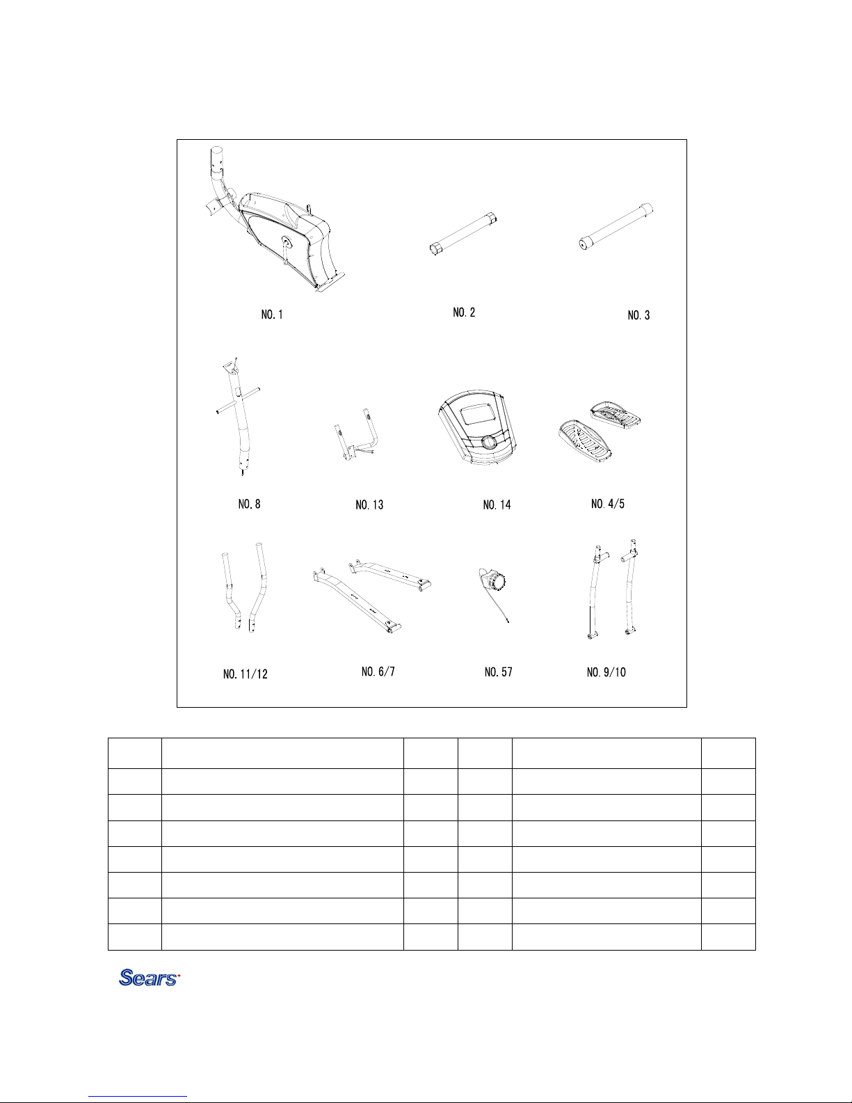
Pre-Assembly Check List
PART DESCRIPTION Q’TY PART DESCRIPTION Q’TY
1 Main frame 1 11/12 Top handlebar R/L 2
2/20 Rear stabilizer w/end caps 1 6/7 Pedal tube R/L 2
3/21 Front stabilizer w/transportation wheels 1 57 Tension control w/cable 1
8 Upright 1 9/10 Bottom handlebars R/L 2
13 Stationary handlebar w/pulse 1 Inner box 1
14 Monitor 1 Manual 1
4/5 Pedal R/L 2

Maurice Pincoffs Canada ©2013
4
Hardware Packing List
Part No. Description Q’ty Drawings
15 Carriage bolt M10 x 75 4
18 Domed nut M10 4
15
18
19 Curve washer Φ22 x Φ10 4
22 Lock knob 4
19
22
23 Hex head bolt M8 x 45 4
24 Hinge bolts 2
23
24
25 Wave washer 2
26 Flat washerΦ13 x Φ 27 2
25
26
27 Nut L/R 2
28 PVC cap M10 6
27
28
29 Nylon locknut M10 2
30 Flat washer Φ10 x Φ 22 2
29
30
31 Sleeve 2
32 Hex head bolt M10 x 78 2
31
32
33 Allen screw M8 x 16 6
34 Curve washer Φ20 x Φ8 6
33
34
36 Hex head screw M10 x 20 2
37 Spring washer Φ10 2
36
37
38 Flat washer Φ10 x Φ32 2
39 D type washer 2
38
39
41 Allen bolt M6 x 12 4
42 Carriage bolt M10 x 75 4
41 42
79 Allen key 6mm 1
80 Allen key 4mm 1
79
80
81 Allen key 8mm 1
82 Wrench 1
81
82
83 Wrench 1
83
Note:
1. Above described parts is the hardware needed to assemble this machine. Before you start to
assemble, please check to ensure all parts are included for assembly.
Maurice Pincoffs Canada ©2013
5
Assembly Instruction
This manual is designed to help you easily assemble, adjust and use this machine. Please read this
manual carefully. For the sake of familiarizing yourself with the parts identified in the instruction,
first study the overview drawing.
Set all parts in a clear area on the floor and remove the packing material. Refer to the parts list for
help to identify the parts.
It will take two people to assemble your unit.
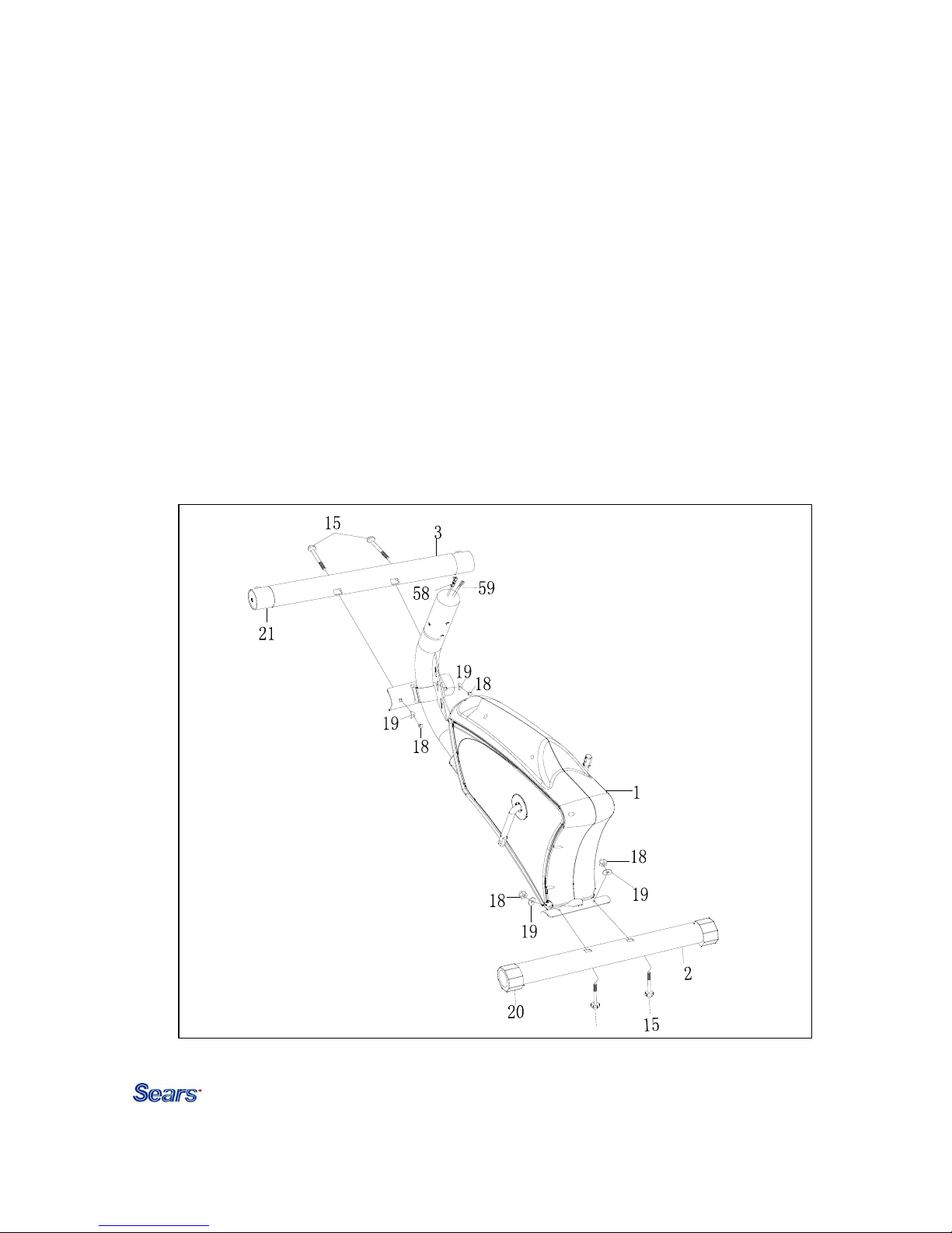
STEP 1
Attach the front stabilizer (3) with transportation wheels (21) to the front of the main frame (1)
securing with two carriage bolts (15), two curve washers (19) and two domed nuts (18).
Attach the rear stabilizer (2) with end caps (20) to the rear of the main frame (1) securing with
two carriage bolts (15), two curve washers (19) and two domed nuts (18).
Maurice Pincoffs Canada ©2013
6
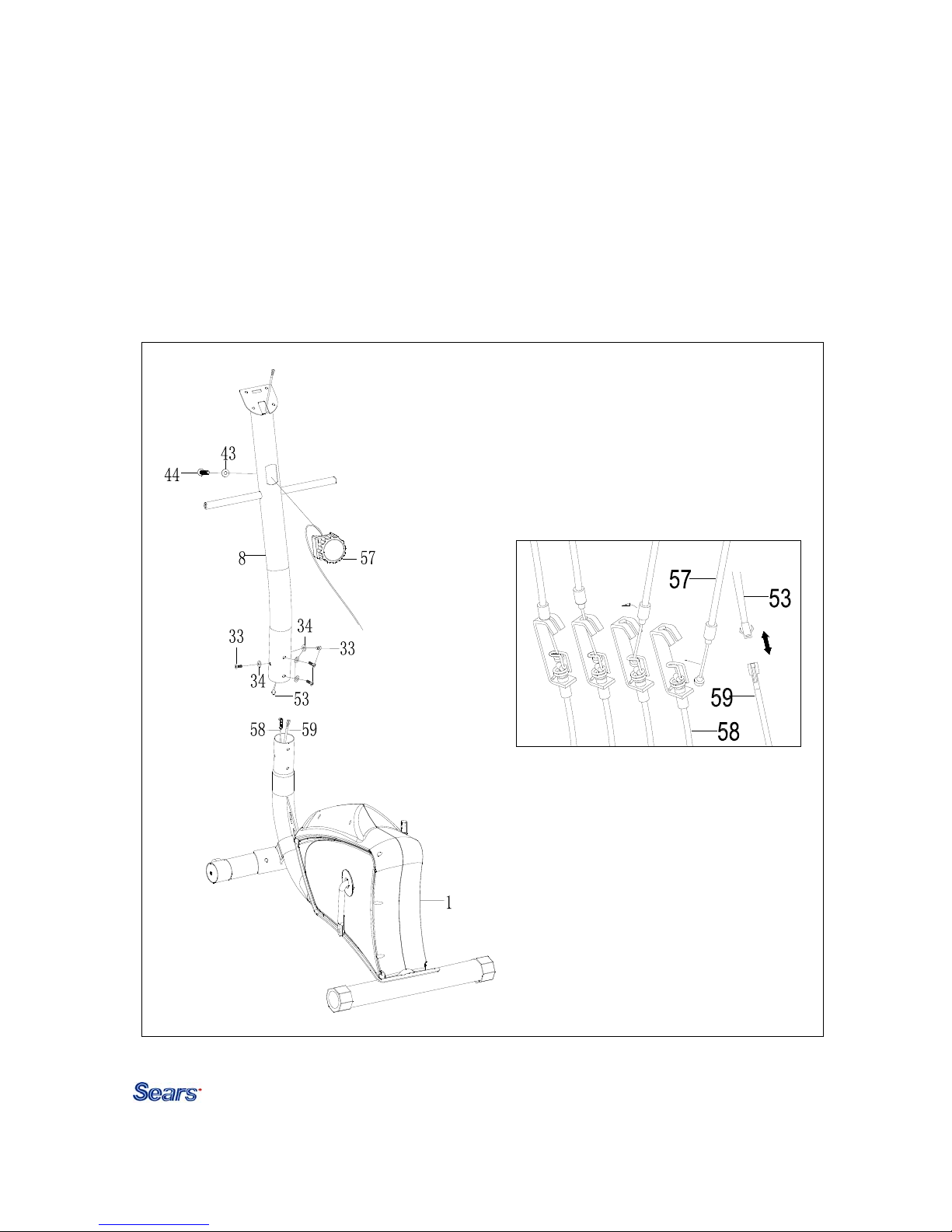
STEP 2
Connect the extension sensor wire (53) from the upright (8) to the sensor wire (59).
Insert the cable of the tension control (57) into the opening of the upright (8). Secure
using one flat washer (43) and one screw (44) which are pre-assembled on the tension
control.
Connect the tension control w/cable (57) from the upright (8) to the extension tension
control cable (58). (See insert)
Insert the upright (8) into the main frame (1). Secure using four allen bolts (33) and
four curved washers (34).
Maurice Pincoffs Canada ©2013
7
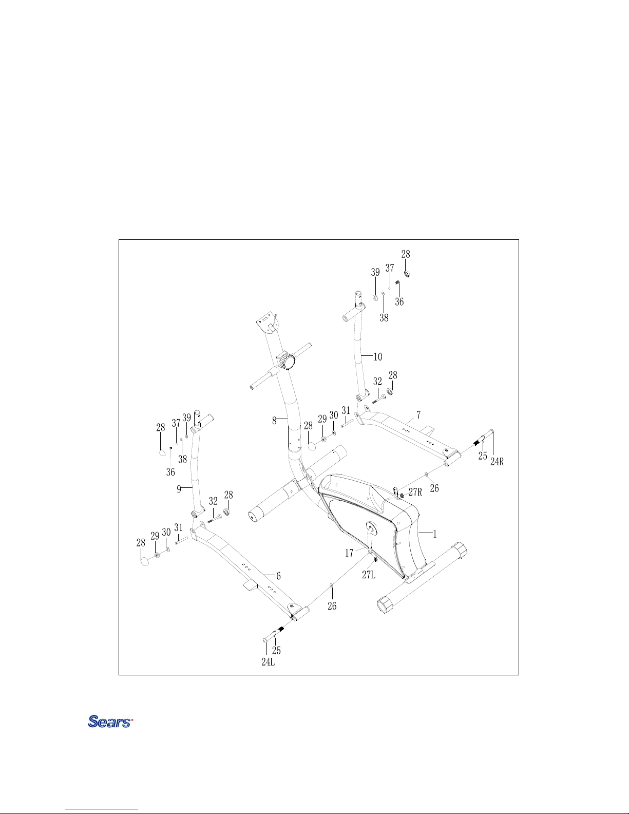
STEP 3
Attach the bottom left handlebar (9) to the left side axle of the upright (8). Secure using D type
washer (39), one flat washer (38) one spring washer (37), and one hex head screw (36). Attach
the PVC cap (28) onto the hex head screw (36).
Attach the left pedal tube (6) to the bottom left handlebar (9). Slide the sleeve (31) into the left
pedal tube and the bottom left handlebar. Secure using one hex head bolt (32), one flat washer
(30), one nylon locknut (29) and two PVC caps (28).
Attach the left pedal tube (6) to the left crank arm (17). Secure using one hinge bolt (24L), one
wave washer (25), one flat washer (26) and one nut (27L).
Repeat for the bottom right handlebar (10).
Maurice Pincoffs Canada ©2013
8
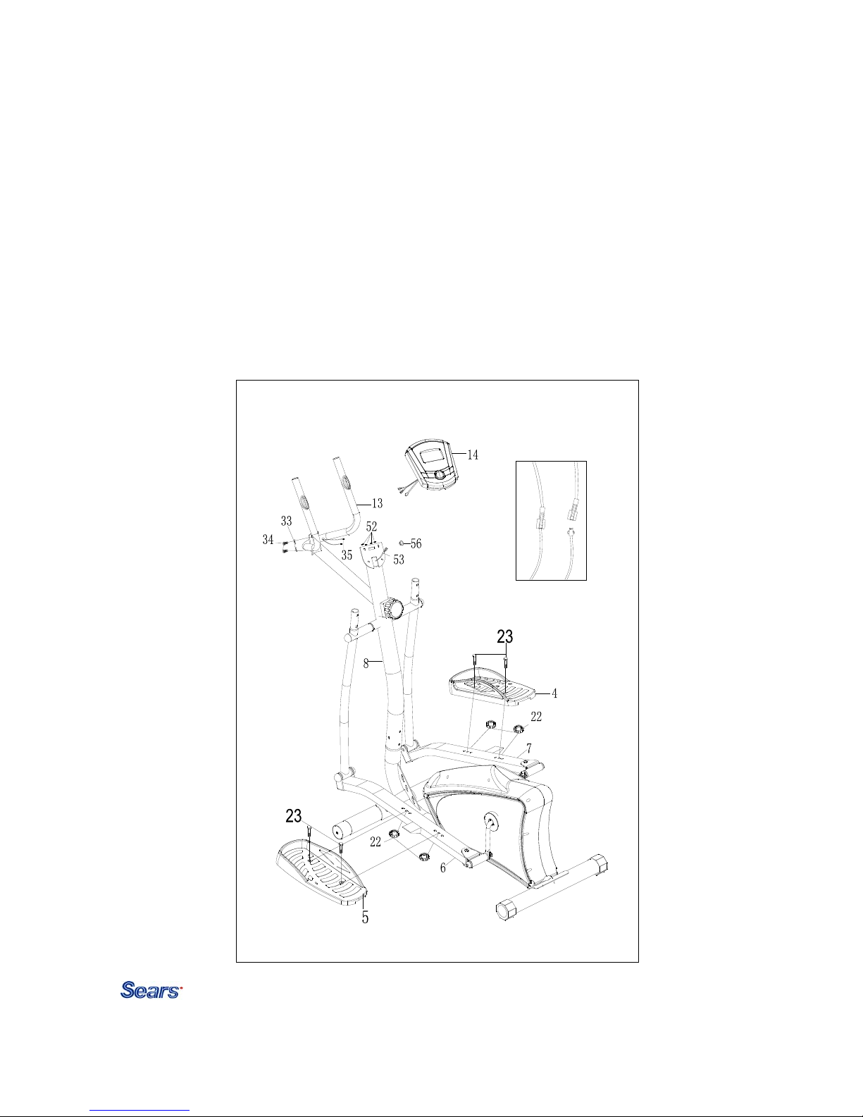
STEP 4
Attach the Left pedal (5) to the left pedal tube (6). Secure in your desired position using two hex
head bolts (23) and two lock knobs (22). Repeat for the Right pedal (4).
Attach the stationary handlebar (13) with hand pulse (35) to the back of the upright (8). Secure
using two allen bolts (33) and two curve washers (34).
Insert the hand pulse wires (35) through the grommet (56) and pull it out from the hole on the
top of the upright (8), then connect the hand pulse wires (35) to the back of the monitor (14).
Connect the extension sensor wire (53) to the back of the monitor (14).
Attach the monitor (14) to the bracket of the upright (8). Secure using four screws (52) which
were pre-assembled on the back of monitor.
Note: It will be necessary to move the hand pulse wire (35) around the upright post and away
from the monitor bracket to avoid pinching the wires.
 Loading...