

T:F. 26
-
#27
l,lovember
14, 1985
t
ru#J
llrlf
Depa,rtment
731.A
Tbronto
TECHNICAL
FLASH
SEtrVICE
INFOF]MATION
@AOO
DUSHWASHER
Dd@DE&
z'5-9900,
DEPARTT.IENI 731A _ ISRRY
STDES
KENMORE DISHWASHER
MODEL
753900
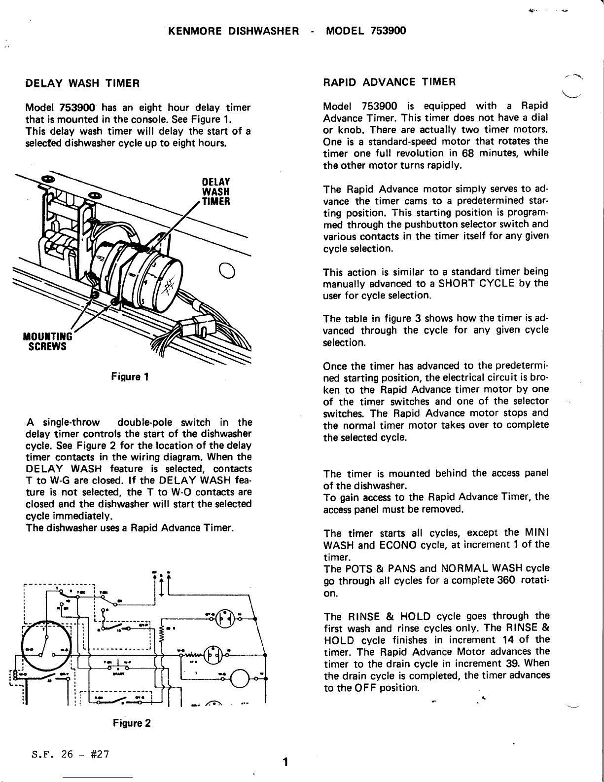
DELAY
WASH
TIMER
Model
753900
has
an
eight hour delay
timer
that
is mounted in
the console. See
Figure
1.
This delay
wash timer will delay the
start
of a
selected
dishwasher
cycle
up to
eight hours.
A single-throw
double-pole
switch in the
delay timer controls the start
of
the
dishwasher
cycle. See
Figure
2
for
the
location
of
the delay
timer contacts
in
the
wiring diagram.
When the
DELAY WASH
feature
is
selected, contacts
T
to
W-G
are closed. lf the DELAY
WASH
fea-
ture
is not
selected,
the T
to
W-O contacts
are
closed and the
dishwasher will
start the selected
cycle
immediately.
The
dishwasher uses a Rapid
Advance
Timer.
RAPID
ADVANCE
TIMER
Model
753900
is
equipped
with
a
Rapid
Advance
Timer.
This
timer does
not have a dial
or
knob. There
are actually two
timer
motors.
One
is a standard-speed
motor that
rotates
the
timer
one
full
revolution
in
68
minutes,
while
the
other
motor turns
rapidly.
The
Rapid Advance
motor
simply
serves
to ad-
vance
the
timer cams
to a
predetermined
star'
ting
position.
This starting
position
is
program-
med
through
the
pushbutton
selector
switch
and
various
contacts
in the
timer itself
for
any
given
cycle selection.
This action
is
similar
to a standard
timer
being
manually
advanced
to a SHORT
CYCLE
by the
user
for cycle selection.
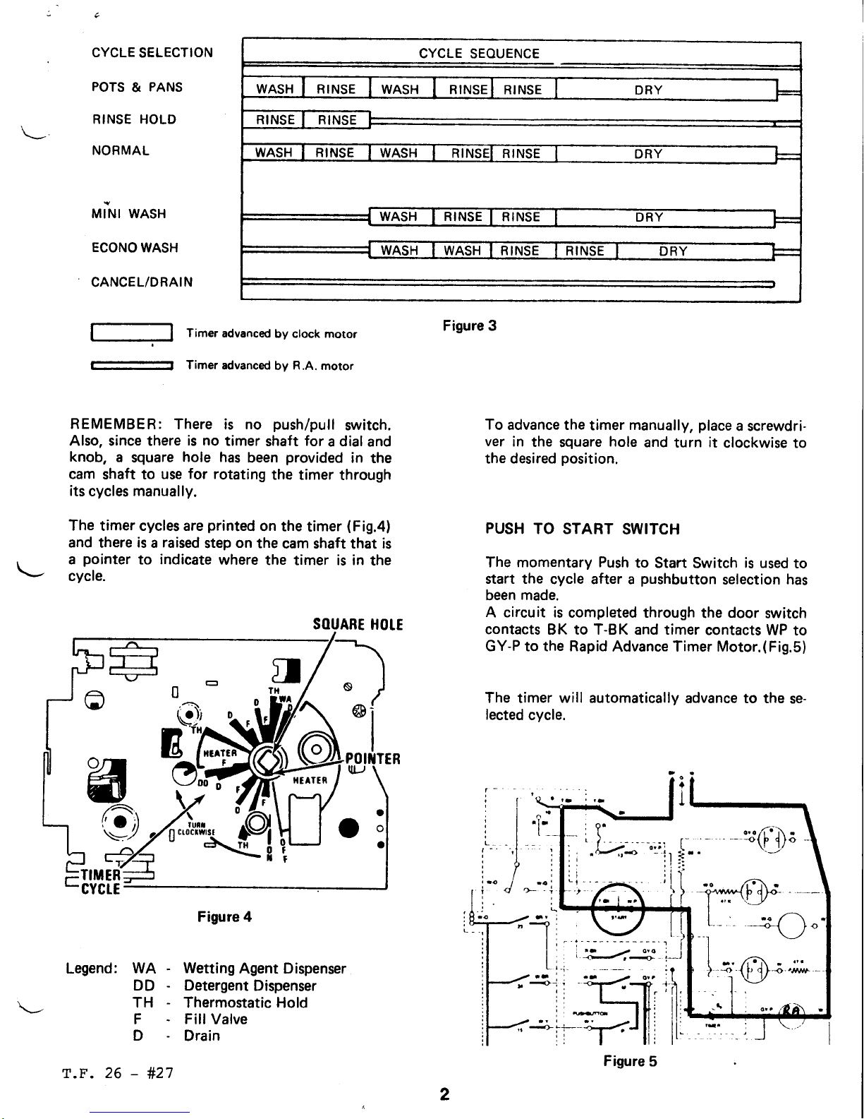
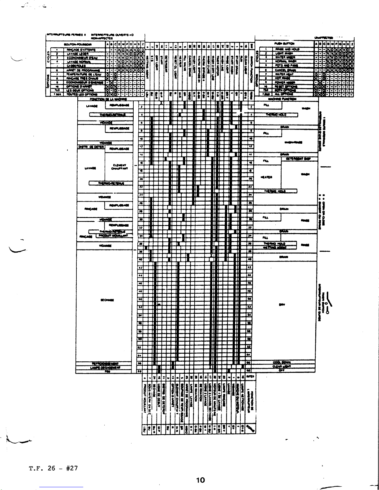
The table
in
figure
3
shows
how
the
timer is ad-
vanced through
the cycle
for
any
given
cycle
selection.
Once
the timer
has
advanced
to the
predetermi-
ned
starting
position,
the
electrical circuit
is bro-
ken to the
Rapid
Advance
timer
motor by one
of the timer switches
and
one
of the selector
switches.
The
Rapid
Advance
motor stops
and
the
normal timer
motor takes
over
to
complete
the
selected
cycle.
The timer
is
mounted behind
the access
panel
of the
dishwasher.
To
gain
access
to
the Rapid
Advance
Timer, the
access
panel
must be
removed.
The
timer starts
all cycles,
except the
MlNl
WASH and
ECONO cycle,
at
increment
1
of the
timer.
The
POTS &
PANS
and
NORMAL
WASH cycle
go
through
all
cycles
for
a
complete
360
rotati'
on.
The
RINSE &
HOLD cycle
goes
through
the
first
wash and
rinse
cycles
only. The
RINSE
&
HOLD
cycle
finishes in
increment
14
of
the
timer.
The
Rapid Advance
Motor advances
the
timer
to the
drain cycle
in
increment
39.
When
the
drain cycle
is completed,
the
timer
advances
to the OFF
position.
\
Fifure
2
Figure
1
1
s.F. 26
-
#27
c
CYCLE
SELECTION
POTS
&
PANS
RINSE HOLD
NORMAL
MINI WASH
ECONO
WASH
CANCEL/DRAIN
|
|
Timer
advanced
by clock motor
-l
Timeradvanced
by
R.A.
motor
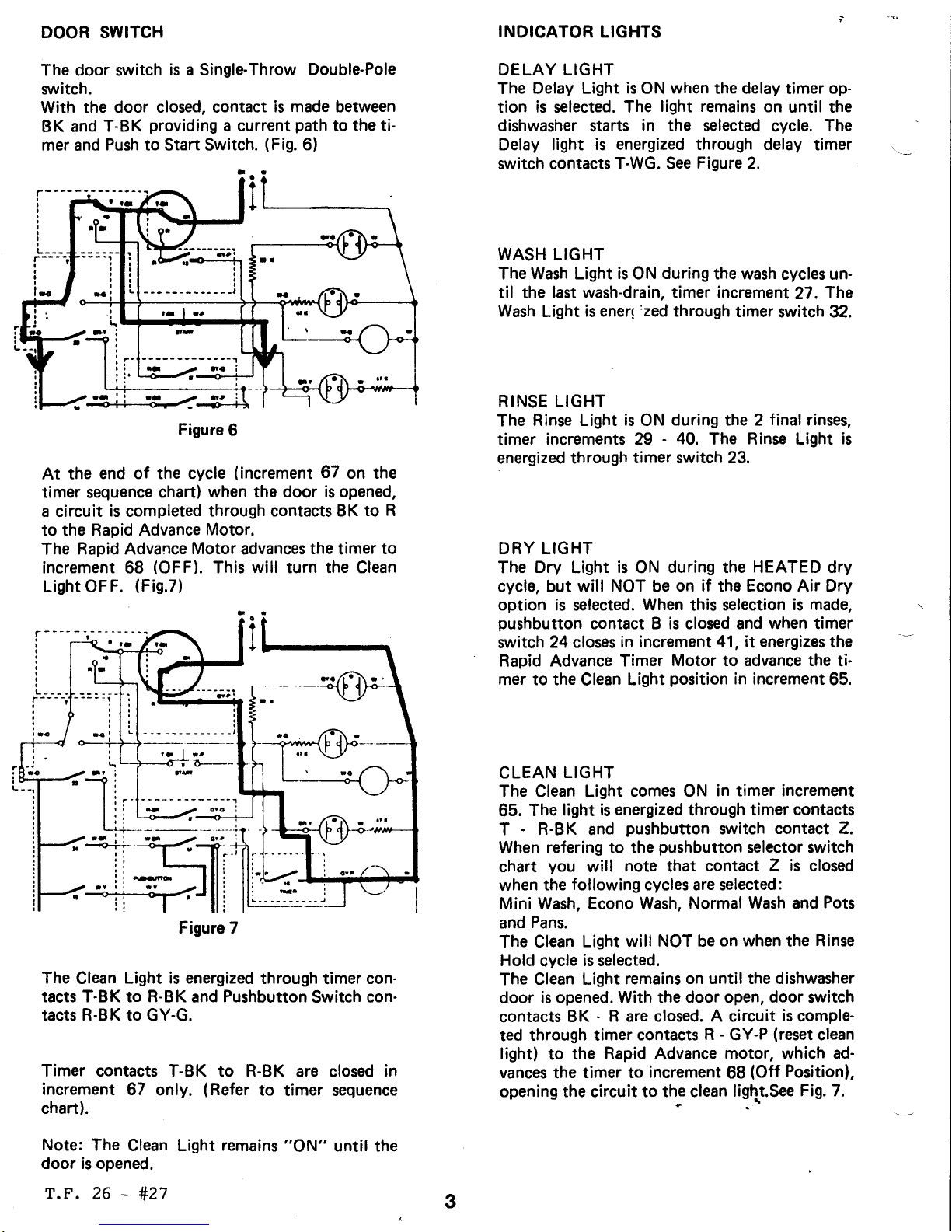
REMEMBER:
There
is
no
push/pull
switch.
Also, since there
is no
timer
shaft
for
a dial and
knob,
a
square
hole has
been
provided
in
the
cam
shaft to
use for rotating
the
timer through
its
cycles manually.
The
timer cycles are
printed
on
the timer
(Fig.4l
and
there
is a raised
step
on
the
cam shaft that is
a
pointer
to indicate
where
the timer is in
the
cycle.
SOUARE
HOIE
Legend:
Figure 4
WA - Wetting
Agent Dispenser
DD
-
Detergent
Dispenser
TH - Thermostatic Hold
F Fill Valve
D
Drain
-
#27
To
advance the
timer
manually,
place
a screwdri-
ver
in
the
square
hole
and
turn
it
clockwise to
the
desired
position.
PUSH
TO START
SWITCH
The momentary Push
to Start
Switch
is used
to
start the
cycle after a
pushbutton
selection has
been
made.
A circuit is
completed through
the
door
switch
contacts
BK to T-BK
and
timer
contacts
WP to
GY-P to the Rapid
Advance Timer Motor.(Fig.5)
The
timer
will automatically
advance to the
se-
lected
cycle.
L-
'
E-'-1--2|
'--_
-)
o,,
Figure 3
o:
o.of\
-
-.\l-i/
t
I
I
_rl
f
,l
#]
2
CYCLE SEOUENCE
tutt
ct0cttYrst
H
o
T.F. 26
Figure
5
DOOR SWITCH
The door switch
is
a SingleThrow
Double-Pole
sruitch.
With the
door closed, contact
is made between
BK
and T-BK
providing
a current
path
to the
ti-
mer
and
Push to Start Switch.
(Fig.
6)
Figure
6
At
the
end of the cycle
(increment
67
on the
timer sequence
chart) when the
door is opened,
a
circuit
is
completed
through contacts BK
to R
to the
Rapid
Advance
Motor.
The
Rapid Advance
Motor
advances
the
timer
to
increment 68
(OFF).
This
will
turn the Clean
Light
OFF.
(Fig.7)
Figure
7
The Clean Light
is energized
through
timer
con-
tacts T-BK to R-BK
and
Pushbutton
Switch con-
tacts R-BK
to GY-G.
Timer contacts T-BK
to R-BK are
closed
in
increment 67
only.
(Refer
to
timer sequence
chaft).
Note:
The
Clean Light
remains
"ON"
until the
door is opened.
r.F. 26
-
#27
INDICATOR
LIGHTS
DELAY LIGHT
The
Delay Light
is
ON
when
the delay
timer
op-
tion is selected. The
light remains
on
until the
dishwasher
starts
in
the
selected
cycle.
The
Delay light
is energized through
delay timer
switch contacts
T-WG.
See
Figure
2.
WASH LIGHT
The Wash Light
is
ON
during
the wash
cycles un-
til the
last wash-drain, timer increment
27.
The
Wash
Light
is ener(
'zed
through
timer
switch 32.
RINSE LIGHT
The
Rinse Light
is
ON
during the
2
final
rinses,
timer increments 29
-
40.
The Rinse Light
is
energized through
timer switch 23.
DRY LIGHT
The
Dry
Light
is
ON
during the HEATED dry
cycle, but
will
NOT
be
on if
the
Econo Air Dry
option is
selected.
When
this
selection
is made,
pushbutton
contact B is closed and when timer
switch 24 closes
in increment 41, it energizes the
Rapid Advance
Timer
Motor to advance the
ti-
mer to the
Clean
Light
position
in
increment
65.
CLEAN
LIGHT
The Clean Light
comes
ON
in timer increment
65.
The
light is
energized
through
timer contacts
T
-
R-BK
and
pushbutton
switch
contact Z.
When
refering
to
the
pushbutton
selector switch
chart
you
will
note that
contact
Z is
closed
when
the
following
cycles are selected:
Mini Wash,
Econo Wash,
Normal Wash and
Pots
and
Pans.
The Clean
Light
will NOT be
on when
the
Rinse
Hold
cycle
is selected.
The Clean
Light
remains
on until the dishwasher
door
is opened. With the
door open, door switch
contacts
BK
-
R are closed. A circuit
is
comple-
ted
through timer
contacts
R
-
GY-P
(reset
clean
light)
to
the
Rapid
Advance
motor,
which ad-
vances
the
timer to
increment
68
(Off
Position),
opening
the circuit to th€ clean
ligtlt.See
Fig. 7.
3
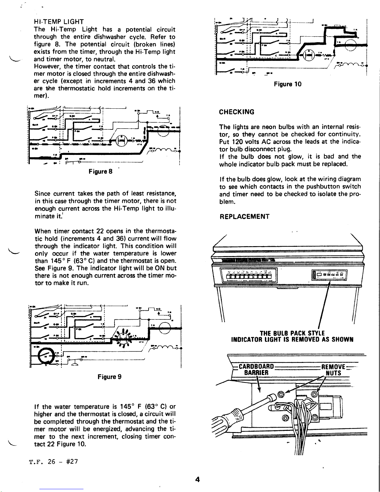
HI.TEMP LIGHT
The
Hi-Temp
Light
has
a
potential
circuit
through the
entire
dishwasher
cycle. Refer to
figure
8. The
potential
circuit
(broken
lines)
exists
from
the timer,
through
the
Hi-Temp
light
and
timer motor,
to
neutral.
However,
the timer
contact
that
controls the
ti-
mer motor is
closed
through the
entire dishwash-
er cycle
(except
in increments 4 and 36
which
are *re thermostatic hold
increments
on
the
ti-
mer).
Since
current
takes the
path
of least
resistance,
in
this
case through
the
timer
motor,
there
is
not
enough
current
across the
Hi-Temp light to illu-
minate
iti
When timer contact
22
opens
in
the thermosta-
tic
hold
(increments
4
and 36) current
will
flow
through
the
indicator light. This condition will
only occur
if the water temperature
is lower
than
145o F
(63'C)
and
the
thermostat
is open.
See
Figure
9. The
indicator light will
be ON
but
there
is
not
enough current across
the timer
mo-
tor to
make it run.
Figure 9
lf the
water temperature
is
145o
F
(63'C)
or
higher and the thermostat
is closed, a circuit
will
be
completed
through
the thermostat and
the ti-
mer
motor
will
be
energized,
advancing
the ti-
mer
to
the
next increment, closing timer con-
tact22
Figure
10.
T.F.
26
-
#27
Figure
10
CHECKING
The
lights
are
neon bulbs
with
an
internal
resis-
tor, so they
cannot be checked
for
continuity.
Put
120
volts
AC across
the
leads at the
indica-
tor bulb
disconnect
plug.
lf the
bulb does
not
glow,
it
is
bad and the
whole
indicator bulb
pack
must be
replaced.
lf
the bulb
does
glow,
look
at the
wiring diagram
to see
which contacts
in the
pushbutton
switch
and
timer
need to be checked to
isolate the
pro-
blem.
REPLACEMENT
THE
BULB
PACK SWIE
IIIDICATOR
TIGHT IS
REMOVEO AS SHOW]I
4
Figure I

REPIACE
THE
UGHTS
AS
SH0WX
t0TE:
THE
l.lcHTS
AtD
THE
sRACI(ET
SIOTS ARE
TUIBEBEO.
EACH
TIGHT
NUST
BE
PIACED
IlI THE
STOT WITH
THE NATCHITG
IIUTEER.
lf
damaged.
the lens
and bezel ara
replaced
as
shown.
TIFT
THE
otD rEfis
OUT.8E
SURE THE
PRITTITG
FACES THE
rROilT WHEI
tlrsTAtutG tEw
t Eils
Pinch
the bezel
sides together
and
slide
out
through
the
front
of console. When
installing
new
bezel,
be
careful not lo
crack it.
Replace
the
bracket and light
assembly
and
the
cardboard
barrier
as shown. Reassemble
lhe
nuts.
5
aoctEE
BABRIEB
r.F.
26
-
#27

SHECKING
PROCEDURE
RAPID ADVANCE
& DELAY TIMER
MOTORS
Disconnect
dishwasher
from electrical
source.
lf the timer will
not
advance through the cycles,
check
the timer
motor
and/or the
rapid
advance
motor.Separate
the
motor lead wire
connection
and
check
for
continuity. lf there
is infinite
resistance
(open
winding)
replace
the
motor.
A
normal
timer
motor
will
show 1900
-
2900
ohms
resistance.
BOTH TITUIER
IIOTORS
ABE MOUI{TED
TO
TIMER
WITH 2
scREws
NOTE:
lf the
harness
disconnect
plug
is
remo-
ved,
the
disconnect
plug
locking
tabs MUST be
locked
into
the timer when reassembled.
The
dishwasher will not
start
if
the
delay
timer
does not
advance.
Check
it
the same
way as
the
timer
motor
and
rapid
advance
motor. lf it is
open, replace it.
The delay timer
switch
should
also be checked. The delay
timer
motor has to
be
removed
to make
this check.
With
time set
on
the timer,
contacts T
-
WG
should
be closed.
(lf
not,
the dishwasher
will start immediately.)
With
no
time on
the
delay
timer,
contacts
T-WO
should show continuity.
lf
the
motor is
bad,
re-
place
it.
When replacing the
delay timer motor and/or
switch:
1.
Face
the terminals
on the
delay timer to-
ward
the back.
2. Connect
the wires
to the
proper
terminals.
The
disconnect
plugs
must
be
fully
engaged.
3.
The
cardboard
barrier
MUST be in
place.
The
shim
washer
(goes
on
the delay timer
shaft)
is only
used to align
the dial
in
the console
ope-
ning.
OELAY
TIMER
MOTOR
DETAY
TIMER
swtTcH
coiri
R0t
ERACKET
6
Tlirl
t/o
O
oo
a\
sxlm
WASHER
T?r?
26
-
#27
ERAC

Select
Cycle
and Option
CYCLES:
10
PUSHBUTTON
MODEL
Firmly
press
the correct button
forthe
cycle
you
wish
and
push
option selection button
for
d€sired
option oroptions. Set
D€lay
Wash
if
desired.
Push
start button. When the Delay indicator
light is
on, the dishwasher
lvash
aclion will detay for tho time
shown
in
the
window.
READ
THIS
CHART TO DECIDE WHICH
CYCLE
YOU
SHOULD
USE.
CYCLE USE THIS
CYCL€
FOR:
WHAT
HAPPENS lN THE
CYCLE
TiM€R
O€LAYS
IF
WATER
IS
NOT
PROPER
TEMP WATER
HEATING HI.TEMP LIGHT
IS
ON
POTS
&
PANS
r-
G
Exlra washing
action
for
heavy
or
cooked
on
soals
ln
thrs
cycle, lhe dishwashsr
will
aulgmatically
heat
lhe water
in
the
first
and se@nd
wash€s, and
in
lhe
final
rinse, if
the
water is
not lhe
proper
temperature.
Cycle lime: Approximately
1
-1
/2
lo 2
hours,
dependang
on
lhe
lame
needed
to
heal
the
water.
RINSE
HOLD
A
\
\:.-.',
-
Rinse
partial
loads which will
be
washed later.
Crcle time: Approximately 10 minut€s.
NORMAL
lglt
A
double
wash for normally
soiled
loads.
Cycl€
time: Apprcxamatoly 60 minut€s
Clean
Light
On
Clean
Light
On
Cycle time:
Appfoximately
t4 minutes.
For
normal.
everyday sotled
loads.
(The
ENERGUIDE
label
data
is
based on this cvcle).
ECONO
rgf
MINI
WASH
MINI
lsplt
Wash very
lightly
soiled dishes
such
as
sandwich olales.
desserl
dishes, etc.
NOTE:
Belore
starting
dishwasher, run water
al stnk
until
il is
hot.
ffi
Cycle trme: Approxrmalely
55 minutes
Clean
Lighl On
CANCEL
ANO
DRAIN
tl
-(t-
NOTE:
When
a cycle
is
cancelled,
the timer
will rapidly
advance
to a drain.
You ryill hgar
"clicks
'
as lhe timor
movos
to the drain
gosition.
This
is a normal
sound.
At the
end
of a complete
wash
cycle,
the CLEAN
indicator light
will come on.
To turn ott
the CLEAN
lighl,
open the
dishwasher door
Cancelling a cycle and
selecting a
ngw
one
or
Turning
otl the dishwasher
in
th€ middl€
of a cycle and
draining b€fore selecling a
new
cycle
or
Turning
otl
the
CLEAN
indicalor lighl.
It you have
selocted a cycle
and lhon change
your
mind,
push
ihe Cancel butlon.
This
cancels
lhe cycl6.
Any waiot
in
lho
dishwasher
willdrain
oulolthe
tub. Thistakes ugto2
minules.
The
"Rinse"
lighl will
glow
during this timo.
When lhe drain
is
completed, all
lights will
9o
ofi, and a
new
cyclo
may
bo
sslectod.
lf
you
have
selected a cycle and don'l
want to complete
it.
push
the Cancel and Drain bunon.
When
you
restan the dishrvasher,
select
a cycle. The new cycle
will
starl
ftom ths
beginning.
Check th6 detergont dispenser.
lt may need
lo be
retillod.
7
T.F.
26
-
#27

CYCLE
SELECTION HI-TEMP
POWER MISER SELECTOR
SWITCH
DEI,-AY
WASH CONTROL
START
BUTTON
INOICATOR
LIGHTS
Options
err
ri;irtgt--
f,d
$
"'
U
><
cYcLEs
I OPToNS
0ttlt
? - ,,,,'
t:-t il. LJ LJ
."1
ll7:':'l
-l
- - - -
t"l
iui-
{F
ilj;'.=#i"
When
this option
is
selected,
water
for
lhe
main wash and
final rinse is heated to
145o F.
(630
C.).
As lhe watei
is heated,
the
Water Heat Light
glows
and
washing action continues.
The
cycle time
will be
extended
untilthe water reaches
this t€mperature.
lttakss about one
minute to raise water
temperature one degree.
This
option
is
intended for use
when washingh€avily soiled dishes.
WATER
HEAT
Option cannot be selected
with LIGHT
WASH
or
RINSE
HOLD
cycles.
\
HI.TEMP
HOT
RINSE
Whsn this oplion
is
selected,
the water
forthe tinal rinse will be
heated
to
145o F.
(630
C.).
As ths
water is h€ated, the
water Heat
Light
glows
and
rinsing
action
continues. The cycls time will be
ext€nded until the
water reaches this
temperature. Us€ this option to help dry dishes
faster
and
reduce spotting.
ITJ
5F:'"
Push
Air Dry
button. Eliminates
heat in
the dry cycle. Leave the
washed
dish load in the latched
dishwasher lor
several
hours
or overnight. Or, open the door
fully for a few
seconds to allow
steam
to
escape.
Raise
the door to a closed
position.
Allow
dishes
to dry
for
several
hours.
No.hoat
drylng
may
rerult
in
som€
sponing
ot
glasse!
or
silver.
liems which
do
not dry,easily
(such
as
plastics)
may n€ed towel
drying.
CANCEL
OPTION
lf
you
want
to change
an option,
press
the Cancel
Options
bunon.
A new option
may
be
selected.
DEI-AY
WASH
Delay
Wash
can be
used when
you
want the dishwasher cycle
to slad
1/2
to I
hours
alter the dishwasher
is
loaded.
For
example, use
Delay Wash to set
the dishwash€r
cycle to
run
in
otf-peak
hours
ot
olectrical
use.
To
set
Delav Wash:
1. Close the door
tlrmly,
2.
Seloct
the number of'hours
(trom
1/2 to 8 hours)
you
want the dishwasher
to
wait
before
the
cycle starts.
3. Turn the Deliy
Wash Control down
until the
window
shows
the
number of
hours
you
s€lected.
The-control can
be moved up or down
to change
your
selection.
lf
you
are
senino a delav
time
less
lhan
t
hour,
turn the control
knob to
t hour then back
to the
desire?
time.'The Delay
indicator light will
glow
when the Delay
Control
is
set.
4.
Firmly
press
the button
for the desired cycle.
5.
Press
the desired Options
bunon(s).
6.
The Delay
indicator light will
glow
until the dishwasher
cycle starts.
The Delay
Wash window
will
shot
the ap,roximate
lime
remaining before the
cycle
begins.
You
can
add an
item to the
dishwasher
load
il
the Delay or
the Wash
indicalor
lights
are
on. Close
the door
firmly.
Indlcstor
Llghtg
These lights-glow during ditt€ront
portions
of
the cycle to
lel
you
know
what
your
dishwasher
is
doino.
The Drlry liqht
olows
when the
dishwashot
cycle
is
s€l
to come
on
at a
later
time.
Th;Washb
tioniqbws until the
last wash
drains-.
The
Rlnr.
v,
light
glows
during
the two
final rinse6.
The
Dry
U
light
glows
during
hsated drying,
but
isbtf if
the Econo
Alr
Dry option
is
selected.
The Clcan
;c'
light
glows
when
the dishwasher
cycle
is
completo.
To turn otf the Clcan
light, open
the
dishwasher door
The Hl-Tempdl light will
glow
to let
you
know that the dishwasher
is delaying
f.or water
heating. Waier
he-ating
oCcurs
durrng the
Pots
and
Pans
cycle
and rvhen
th€ Hi-Temp
.
Wash is
selected.
The
length
of
time lhis light
slays
on
depends
upon
the temp€rature ol
the water enlering the dishwasher.
The
lower
the water temperalure,
the
longer tho
light
wilt stay
on and
the longer the dishwasher
will
operale.
Note: Thc llght wlll
not comc
on
lf
thc
watcr lg at the corroct
temp€ralurc,
I
r+
-
U
U:ii't
-rY.
r.F.
26
-
#27

iB
irrEa
aat
--orMnp-
rarrl
Itrt''.rtE
c-
ra
.-r1
n+
rrllttatrfrDtI.E,
rt
:a
-.Annro-
rrlr-t-trItlrE rtalrt
tt-
a
+fYfrO-
lrrrrl
E
rtt.rl/tt
'o7ea
Fu-l|'
irntltrrlFa/l
n|t
.l
-t
crtlraa
,rtaGtrol
-oQot
-
trl.rtE
ItLIlta
b\J
El-tt!.
rilF
rLtrtrt
-oS[*'.
.DUI'
urrr!
rtilrl
.r
o1f1}-
t
t-!-lrrlr.ot
!'tatrtlr-c-
-
-d)-.
t
rula
urrtrrL
-.-f)-
'
alrutt
rttlratFr
araS
ISTH
-.Q-.
C,'EGT
rgialqt.-a
e',{}--
l^iltatE
l!|lualrtrlr
'{:
..rtrt5
!i.II'Il
?i
ll
I
".l
at
.l
;
f----'1-----t
I
'a
.I-!'
! I'!e
lt:
irllrtiD-!roIracr,|r-GtD.arF
,.
||
I
T.F.
26
-
#27
t4-----i
,lXa
r
r?tratrlat
qnna.O
-rJrtctta
li
il
1
t:
il
tf
ir
lll
*1
10
T-F.
26
-
#27
 Loading...