

Sears 987.889,Craftsman 987.889000 Owner's Manual
I , r_ --.
OWNER'S
MANUAL
MODEL NO.
987.889000
,_ Caution:
Read and Follow
All Safety Rules
and Instructions
Before Operating
This Equipment,
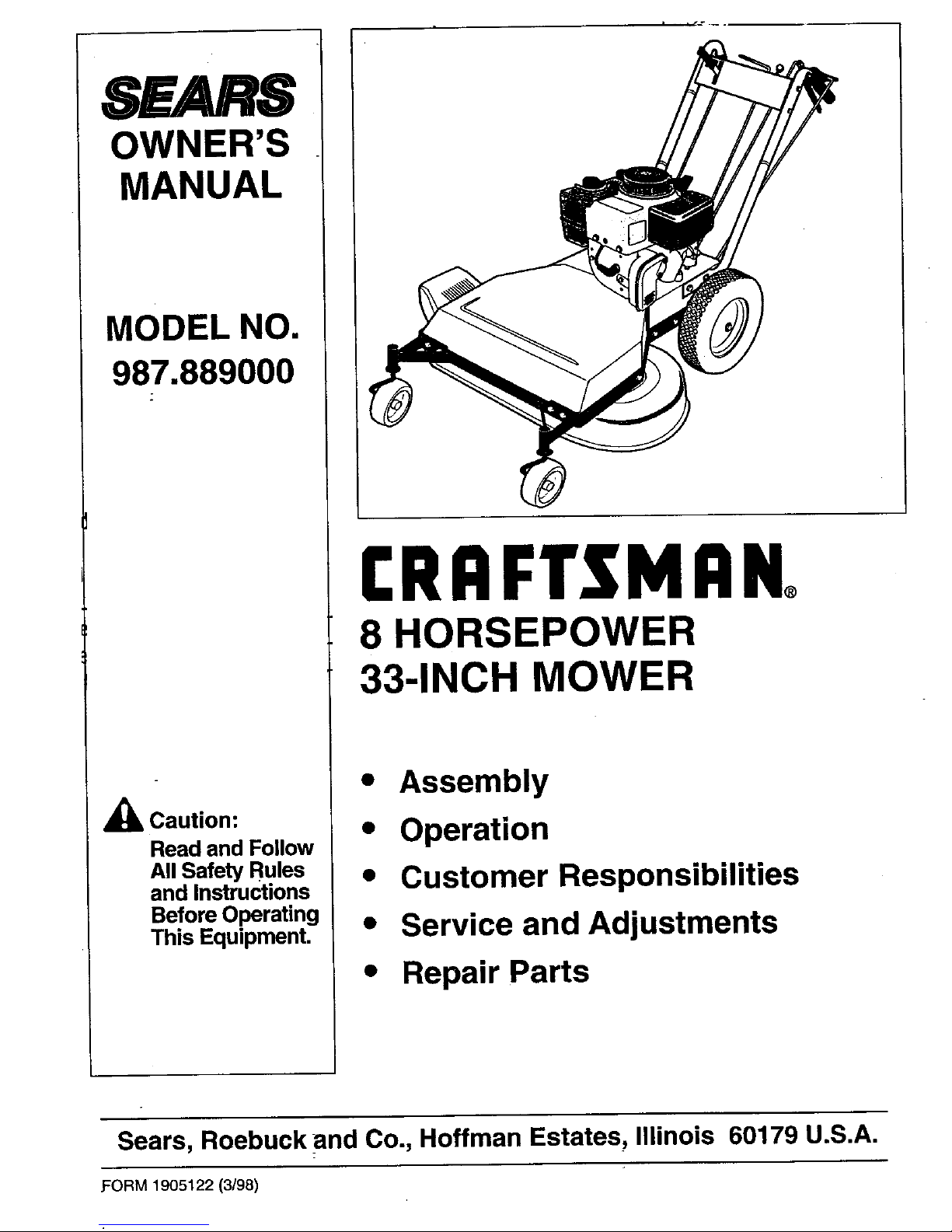
CRAFTSMAN°
8 HORSEPOWER
33-INCH MOWER
• Assembly
• Operation
• Customer Responsibilities
• Service and Adjustments
• Repair Parts
Sears, Roebuck and Co., Hoffman Estates, Illinois 60179 U.S.A.
.FORM 1905122 (3/98)
SAFETY RULES
A AUTION: ALWAYS DISCONNECT SPARK PLUG WIRE AND PLACE WIRE WHERE IT
CANNOT CONTACT SPARK PLUG TO PREVENT ACCIDENTAL STARTING WHEN SET-
TING UP, TRANSPORTING, ADJUSTING OR MAKING REPAIRS,
IMPORTANT
Safe Operation Practices for Walk-Behind Mowers
This curing machine is capable of amputating hands and feet and tl_rowing objects. Fail-
ura to observe the following safety instructions could result in serious injury or death.
8,
WARNING:
The engine exhaust from this product
containschemicalsknownto the State of
Californiatocausecancer,birthdefects,or
otherreproductiveharm.
I. GENERALOPERATION
1.
Read, understand, and follow all instructions on the
machine and in the manuals. Be thoroughly familiar
with the controls and the proper use of the mower
before starting.
2. Do not put hands or feet near or under rotatingparts.
Keep clear of the mower blade and discharge open-
ing at all times.
3.' Only allow responsible individuals, who are familiar
with the instructions, to operate the mower.
4. Clear the area of objects such as rocks, _oys, wire,
bones, sticks, etc., which could be picked up and
thrown by the blade.
5. Be sure the area is clear of other people before
mowing. Stop mower if anyone enters the area.
Keep bystanders at least 25 feet away from the area
of operation.
6.
7.
Do not operate the mower when barefoot or wearing
open sandals. Always wear substantial foot wear.
Do not pull mower backwards unless absolutely nec-
essary. Look down and behind before and while
moving backwards.
.
10.
11.
Do not operate the mower without proper guards,
plates, grass catcher or other safety protective de-
vices in place.
Refer to provided instructionsfor proper operation
and installation of accessories. Only use acces-
sories approved by Sears, Roebuck and Co.
Stop the blade when crossing gravel drives, walks,
or roads.
Stop the engine and disconnect the spark plug wire
from the spark plug whenever you leave the unit, be-
fore cleaning the mower or unclogging the chute.
12. Shut the engine off, wait until the blade comes to a
complete stop, and disconnect the spark plug wire
before installing or removing the mulcher cover or
the optional grass catcher. Make certain that the
grass catcher is securely attached before operating
the mower. Empty the grass catcher after each use-
decomposing debris could generate enough heat to
catch fire.
13. Mow in daylight or good artificial light.
14. Do not operate the mower while under the influence
of alcohol or drugs.
15. Never operate mower in wet grass. Always be sure of
your footing; keep a firm hold on the handle and walk;
never run.
16. Disengage the Wheel Drive Lever on self-propelled
models before starting the engine.
17. If the unitshould start to vibrate abnormally, stop the
engine and disconnect the spark plug wire. Then
check immediately for the cause. Vibration is gener-
ally a warning of trouble.
I
,_ LOOK FOR THIS SYMBOL TO POINT OUT IMPORTANT SAFETY PRECAUTIONS. I
IT MEANS- ATTENTION!!! BECOME ALERT!I! YOUR SAFETY IS INVOLVED.
I

SAFETY RULES
18. Always wear safety goggles or safety glasses with
side shields when operating mower.
19. Watch for traffic when operating near, or when cross-
ing roadways.
20. Never attempt to carry children or other passengers
on the mower. They could fail off and be seriously in-
jured, or they could interfere with the safe operation
of the mower.
21.
Check the operation of the Operator Presence Con-
trol before each use. See the Customer Responsibili-
ties Section of this manual for instructions. Ifthe
mower blades rotate longer than three seconds after
the Operator Presence Control is released, the sys-
tem is not working properly. Immediately contact
your local Sears Service Center/Department for in-
structions. Do not use the mower until the mecha-
nism is repaired.
22.
The mower is equipped with a safety discharge
chute, comes with a special mulcher cover and offers
an optional grass catcher. The safety discharge
chute must be working properly at all times. Never
attempt to disconnect or otherwise cause this dis-
charge chute to cease working. If used, mulcher
cover or grass catcher attachment must be installed
properly and function correctly. Do not use your
equipment otherwise.
23.
Never runthe engine in an enclosed area. Engine ex-
haust contains carbon monoxide, a deadly gas that is
ododess, colodess, and tasteless. Always run the en-
gine outdoors and make sure there is adequate
ventilation.
II. SLOPEOPERATION
Slopes are a major factor related to slip and fall acci-
dents which can result in severe injury. All slopes
require extra caution. If you feel uneasy on a slope,
do not mow it.
DO:
Mow across the face of slopes; never up and down.
Exercise extreme caution when changing direction on
slopes. Avoid slopes greater than 15o.
Remove objects such as recks, tree limbs, etc.
Watch for holes, ruts, orbumps. Tall grass can hide
obstacles.
DO NOT:
Do not mow near drop-offs, ditches, or embankments.
The operator could loose footing or balance.
Do not mow excessively steep slopes.
Do not mow on wet grass. Reduced footing could
cause slipping.
III. CHILDREN
Tragic accidents can occur if the operator is not alert
to the presence of children. Children are often at-
tracted to the mower and to the mowing activity.
Never assume that children will remain where you
last saw them.
1. Keep children out of the mowing area and under the
watchful care of a responsible adult.
2. Be alert and turn mower off ifchildren enter the area.
3. Before and while moving backwards, look behind
and down for small children.
4. Never allow children to operate the mower.
5. Use extra care when approaching blind comers,
shrubs, trees, or other objects that may obscure
vision.
IV.SERVICE
.
2.
3
.
5.
Use extra care in handling gasoline and other fuels.
They are flammable and their vapors are explosive.
a) Use only an approved container.
b) Never remove gas cap or add fuel when the en-
gine is-running.Allow engine to cool before refu-
eling. Do not smoke.
c) Never refuel the machine indoors.
d) Never store the machine or fuel container inside
where there is an open flame, such as a water
heater, etc.
e) Move mower away from any gasoline fumes be-
fore starting the engine.
Never run an engine inside a closed area.
Never make adjustments or repairs with the engine
running. Disconnect the spark plug wire and keep
the wire away from the plug to prevent accidental
starting.
Keep all nuts and bolts, especially the blade attach-
ment bolts, tight and keep equipment in good condi-
tion.
Never tamper with safety device s. Check their opera-
tion regulady.
SAFETY RULES
6. Keep mower free of grass, leaves or other debds
build-up. Clean up oil or fuel spillage. Allow mower to
cool before storing.
7. After stdking an object, stop the engine and discon-
nect the spark plug wire. Inspect the mower and re-
pair, if necessary, before restarting.
8. Never attempt to mal_e mower cutting height adjust-
ments while the engine is running.
9. Grass catcher components are subject to wear, dam-
age and deterioration, which could expose moving
parts or allow objects to be thrown. Frequently check
components and replace with Sears recommended
parts, when necessary.
10. Mower blades are sha_rpand can cut. Wrap the blade
or wear gloves, and use extra caution when servicing
them.
11. Do notchange the engine govemor setting or over-
speed the engine.
12. Do nottouch engine parts which may be hot from
operation. Allow parts to cool completely before in-
specting, cleaning or repairing the mower.
13. To access the underside of the mower, tip the mower
rearward. Do not tip the mower forward or on either
of its sides, unless specifically advised to do so in
this manual.
14. Maintain or replace safety and instructional decals.
Refer to the Repair Parts Section for replacement
decal information.
4
CONGRATULATIONS on your purchase of a Craftsman
33-Inch Mower. It has been designed, engineered and
manufactured to give you the best possible dependability
and performance.
Should you experience any problems you cannot easily
remedy, please contact your nearest Sears Service
Center/Department. We have competent, well-trained
technicians and the proper tools to service or repair this
machine.
Please read and retain this manual. The instructions will
help you assemble and maintain your machine properly.
Always observe the "SAFETY RULES."
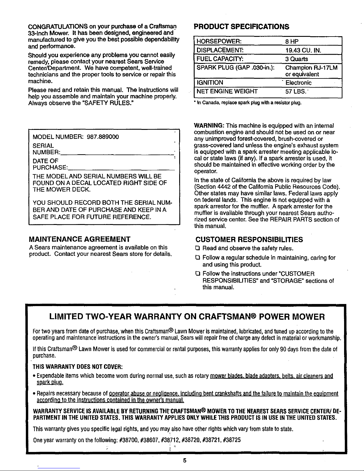
PRODUCT SPECIFICATIONS
HORSEPOWER: 8 HP
DISPLACEMENT: 19.43 CU. IN.
FUEL CAPACITY: 3 Quarts
SPARK PLUG (GAP .030-in.): Champion RJ-17LM
or equivalent
IGNITION "Electronic
NET ENGINE WEIGHT 57 LBS.
*InCanada,replacesparkplugwitharesistorplug.
MODEL NUMBER: 987.889000
SERIAL
NUMBER:
DATE OF
PURCHASE:.
THE MODELAND SERIAL NUMBERS WILL BE
FOUND ON A DECAL LOCATED RIGHT SIDE OF
THE MOWER DECK.
YOU SHOULD RECORD BOTH THE SERIAL NUM-
BER AND DATE OF PURCHASE AND KEEP IN A
SAFE PLACE FOR FUTURE REFERENCE.
MAINTENANCE AGREEMENT
A Sears maintenance agreement is available on this
product. Contact your nearest Sears store for details.
WARNING: This machine is equipped with an internal
combustion engine and should not be used on or near
any unimproved forest-covered, brush-covered or
grass-covered land unlessthe engine's exhaust system
is equipped with a spark arrester meeting applicable lo-
cal or state laws (if any). If a spark arrester is used, it
should be maintained in effective working order by the
operator.
In the state of California the above is required by law
(Section 4442 of the California Public Resources Code).
Other states may have similar laws. Federal laws apply
on federal lands. This engine is not equipped with a
spark arrestor for the muffler. A spark arrester for the
muffler is available through your nearest Sears autho-
rized service center. See the REPAIR PARTS section of
this manual.
CUSTOMER RESPONSIBILITIES
D Read and observe the safety rules.
O Follow a regular schedule in maintaining, caring for
and usingthis product.
O Follow the instructionsunder "CUSTOMER
RESPONSIBILITIES" and "STORAGE" sections of
this manual.
LIMITED TWO-YEAR WARRANTY ON CRAFTSMAN® POWER MOWER
Fortwo yearsfrom dateof purchase,whenthis Craftsman® Lawn Mowerismaintained,lubricated,andtuned upaccordingto the
operatingand maintenanceinstructions in the owner's manual,Searswill repairfree of chargeanydefectin material orworkmanship.
If this Craftsman® LawnMower is usedfor commercialor rentalpurposes,this warrantyappliesfor only 90 days from the date of
purchase.
THISWARRANTYDOESNOTCOVER:
• Expendableitemswhichbecome worn during normaluse,such asrotary mowerblades,bladeadanters,belts,air cleanersand
• Repairsnecessary becauseof ooeratorabuseor negligence,includingbentcrankshaftsandthefailureto maintainthe eouiDment
according to the instructionscontainedinthe owner's manual.
WARRANTYSERVICEISAVAILABLEBYRETURNINGTHE'CRAFTSMAN®MOWERTOTHENEARESTSEARSSERVICECENTER]DE-
PARTMENTINTHE UNITEDSTATES.THISWARRANTYAPPLIESONLYWHILETHISPRODUCTIS INUSEIN THEUNITEDSTATES.
This warrantygivesyou specificlegalrights,andyou may also haveotherrightswhichvaryfrom stateto state.
Oneyearwarranty on the following: #38700, #38607, #38712, #38720, #38721, #38725
TABLE OF CONTENTS
SAFETY RULES ................................................... 2
CUSTOMER RESPONSIBILITIES ................. 5, 23
PRODUCT SPECIFICATIONS .............................. 5
WARRANTY .......................................................... 5
-ACCESSORIES AND ATTACHMENTS ................ 7
ASSEMBLY ........................................................... 8
OPERATION ....................................................... 13
CUSTOMER RESPONSIBILITIES ................. 5, 23
SERVICE AND ADJUSTMENTS ........................ 26
STORAGE ........................................................... 34
TROUBLESHOOTING ........................................ 35
DECALS ................... ,.................... ;..................... 36
REPAIR PARTS - MOWER ................................. 37
REPAIR PARTS - ENGINE ................................. 46
PARTS ORDERING/SERVICE ........... Back Cover
INDEX
A
Accessories and Attachments .... 7
Adjustments:
Height of Cut .............. 15
Air Cleaner .................. 25
Assembly .................... 8
B
Blade:
Replacement ............. 32
Sharpening ................ 32
Blade Drive Control ........... 14
C
Carburetor .................. 26
Controls:
Blade Drive Control ......... 14
Cutting Height Lever ......... 15
Engine Throttle Control....... 16
Gear Select Lever........... 14
Operator Presence Control.... 13
Wheel Drive Control ......... 15
Customer Responsibilities:
Air Filter .................. 25
Blade Care/Replacement ..... 32
Engine ................. 24-25
Lubrication ................ 23
Spark Plug ................ 26
I}
Decals ..................... 36
E
Engine:
Air Filter .................. 25
Cleaning ................. 24
Oil ...................... 24
Operation ................. 13
Recoil Start Rope .......... 16
Spark Plug ................ 26
Storage .................. 34
F
Features/Controls ............ 13
Fuel Storage ............. 17, 34
Fuel Type ................... 17
G
Gear Select Lever ............ 14
!1
Handlebar:
Assembly .................. 9
I.
Lubrication:
Engine ................ 17, 23
Mower ................... 23
M
Maintenance:
Agreement .................. 5
Schedule ................. 23
Mowing Tips ................. 21
Mulching Cover ........... 15, 18
0
Off-Season Storage ........... 34
Oil ................... 17,23
Operation ................... 13
Operator Presence Control ..... 13
Op_ons ..................... 7
P
Parts List ................ 21-27
Product Specifications .......... 4
R
Recoil Start Rope ............ 16
Repair Parts ................. 37
Responsibilities, Customer ...5, 23
$
Safety Decals ............... 36
Safety Rules ................. 2
Service and Adjustments ....... 26
Spark Plug .................. 26
Specifications ................ 5
Starting/Stopping Engine ....... 19
Storage. ................... 34
T
Troubleshooting .............. 35
g
Unpacking ................... 8
W
Warranty .................... 5
Wheel Drive Control .......... 15
OPERATOR'S POSITION
All references in this Manual
to LEFT and RIGHT sides of
the mower are given from the
operator's position behind the
handlebars (unless specified
: otherwise).
6
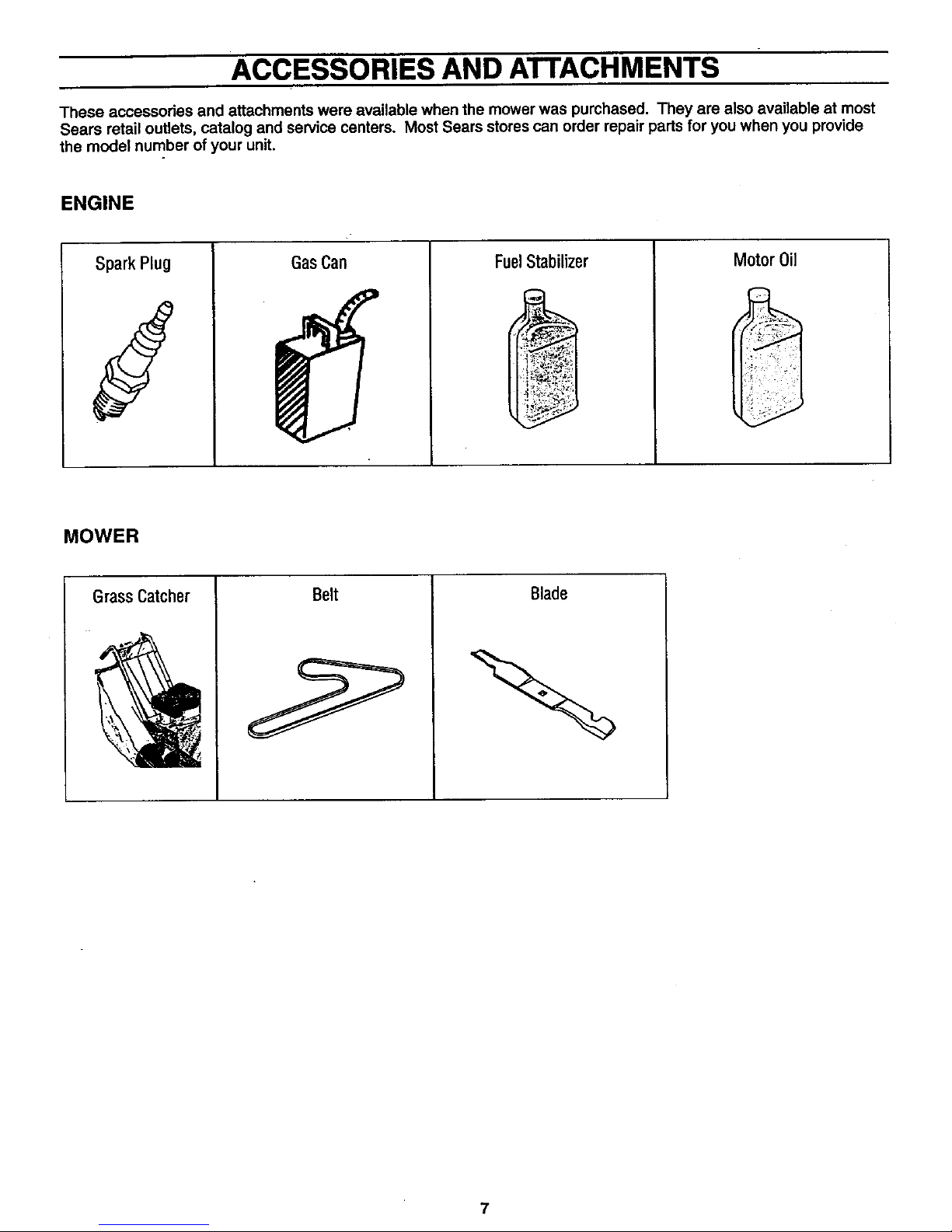
ACCESSORIES AND AI IACHMENTS
These accessories and attachments were available when the mower was purchased. They are also available at most
Sears retail outlets, catalog and service centers. Most Sears stores can order repair parts for you when you provide
the model number of your unit.
ENGINE
Spark Plug
J
GasCan FuelStabilizer
Motor Oil
MOWER
GrassCatcher
Belt
Blade
7
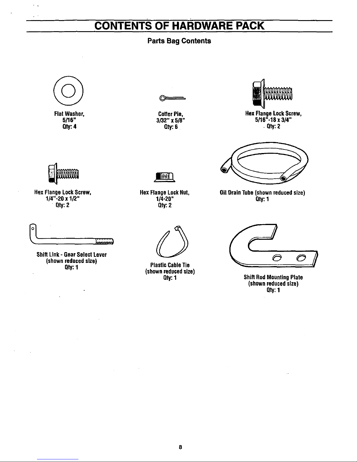
CONTENTS OF HARDWARE PACK
Parts Bag Contents
©
Flat Washer,
5/16"
Qty:4
CotterPin,
3/32" x 5/8"
Oty:6
HexFlangeLockScrew,
5/16"-18 x 3/4"
. Qty:2
HexFlangeLockScrew,
1/4"-20 x 1/2"
Qty:2
HexFlange LockNut,
1/4-20"
Qty:2
Oil DrainTube (shownreducedsize)
Qty:1
ShiftLink- GearSelectLever
(shownreducedsize)
Qty:1
PlasticCableTie
(shownreducedsize)
Qty:1 Shift RodMountingPlate
(shownreducedsize)
Qty:1
ASSEMBLY
Read these instructionsin their en-
tirety before you attempt to assem-
ble or operate your new equipment.
Your new equipment has been as-
sembled at the factory with the ex-
ception of those parts left unassem-
bled for shippingpurposes. To en-
sure safe and proper operation of
your machine, all parts and hard-
ware you install or adjust must be
tightened according to the assem-
bly instructions. Use the correct
tools as necessary to ensure proper
tightness..
ToolsNeededForAssembly:
• (1) 7/16" Wrench
• (1) 3/8" Wrench
• (2) 1/2" Wrenches
• (1) Needle-nose Pliers
• (1) Wire Cutter Pliers
• (1) Tire.Gauge
• (1) Scissors or Pen Knife
UNPACKING
INSTRUCTIONS
• Inspect your machine immediate-
ly. Be sure neither the carton nor
contents have been damaged. If
you find or have reason to sus-
pect damage, contact your near-
est Sears Service Center/Depart-
ment for assistance.
• Cut plastic banding with scissors.
Open box flaps and remove any
packing material from around the
machine. Remove any staples
securing bottom of carton to wood
pallet. Lift off carton. Cut metal
straps secudng unitto base.
Leave unit on base of pallet dur-
ing assembly steps (to safely re-
move unit from base, wait until
you have completed assembly
steps 1-2). Before disposing of
the carton or any of the packing
materials, be sure to check them
thoroughly for any small parts.
• Cut plastic tie straps holding three
long control rods to handlebars.
Also remove any packaging
around the handlebars.
• Perform the assembly on a clean,
level surface. If you need to
move the machine, be careful not
to severely bend any of the con-
trol cables on the equipment.
ASSEMBLYSTEPS
Before starting any assembly
steps, disconnect the engine
spark plug wire from the spark
plug.
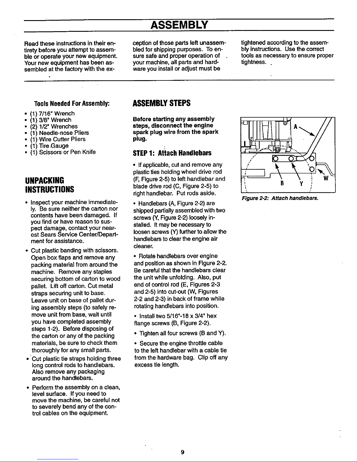
STEP1: AttachHandlebars
• If applicable, cut and remove any
plastic ties holdingwheel drive rod
(F, Figure 2-5) to left handlebar and
blade ddve rod (C, Figure 2-5) to
right handlebar. Put rods aside.
• Handlebars (A, Figure 2-2) are
shippedpartially assembled with two
screws (Y,Figure2-2) loosely in-
stalled. It may be necessary to
loosen screws (Y) further to allow the
handlebars to clear the engine air
cleaner.
• Rotate handlebars over engine
and position as shown in Figure 2-2.
Be careful that the handlebars clear
the unit while unfolding. Also, put
end of control rod (E, Figures 2-3
and 2-5) into cut-out (W, Figures
2-2 and 2-3) in back offrame while
rotatinghandlebars into position.
• Install two 5/16"-18 x 3/4" hex
flange screws (B, Figure 2-2).
• Tighten all four screws (B and Y).
• Secure the engine throttle cable
tothe left handlebar with a cable tie
from the hardware bag. Clip off any
excess tie length.
, B Y ,
Figure 2-2: Attach handlebars.
9
ASSEMBLY
STEP2: AttachControlRods
WARNING
The controlrodsare adjusted
at the factory and should not
require additional adjustment
during assembly. After as-
sembling unit, controlrodad-
justment should be checked
(and re-adjusted, if neces-
sary) accordingto information
in "Customer Responsibili-
ties" Section. Severe person-
a] injury or property
damage could result from
not following this
instruction.
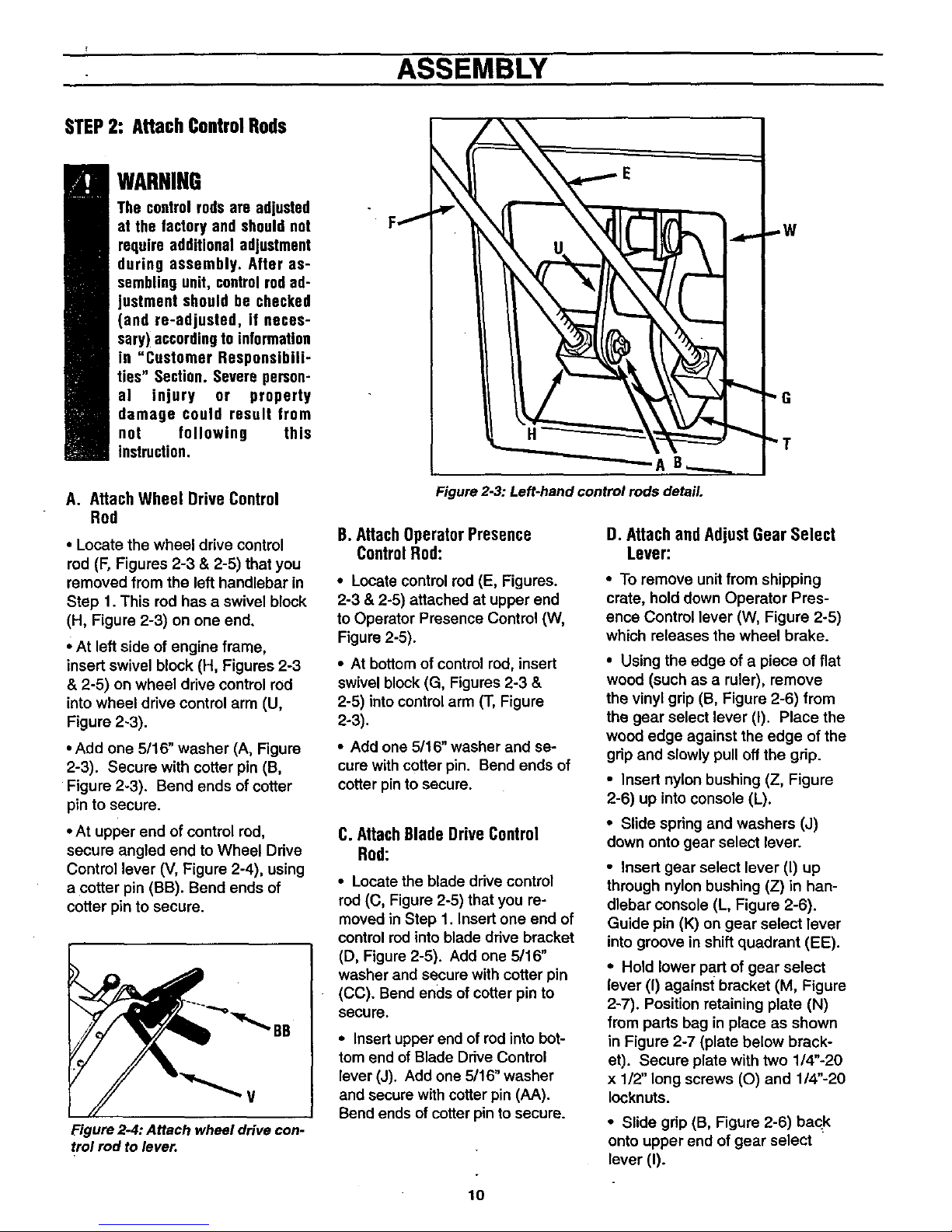
A. AttachWheel DriveControl
Rod
• Locate the wheel drive control
rod (F, Figures 2-3 & 2-5) that you
removed from the left handlebar in
Step 1. This rod has a swivel block
(H, Figure 2-3) on one end.
• At left side of engine frame,
insert swivel block (H, Figures 2-3
& 2-5) on wheel drive control rod
intowheel drive control arm (U,
Figure 2-3).
• Add one 5/16" washer (A, Figure
2-3). Secure with cotter pin (B,
Figure 2-3). Bend ends of cotter
pin to secure.
• At upper end of control rod,
secure angled end to Wheel Drive
Control lever (V, Figure 2-4), using
a cotter pin (BB). Bend ends of
cotter pin to secure.
B
V
Figure 2-4: Attach wheeldrive con-
trolrod to lever.
AB
Figure2-3: Left-handcontrol rods detail.
B. AttachOperatorPresence
ControlRod:
• Locate control rod (E, Figures.
2-3 & 2-5) attached at upper end
to Operator Presence Control (W,
Figure 2-5).
• At bottom of control rod, insert
swivel block (G, Figures 2-3 &
2-5) into control arm (T, Figure
2-3).
• Add one 5/16" washer and se-
cure with cotter pin. Bend ends of
cotter pinto secure.
C.AttachBladeDriveControl
Rod:
• Locate the blade drive control
rod (C, Figure 2-5) that you re-
moved in Step 1. Insert one end of
control red intoblade drive bracket
(D, Figure 2-5). Add one 5/16"
washer and secure with cotter pin
(CC). Bend ends ofcotter pin to
secure.
• Insert upper end of rod into bot-
tom end of Blade Drive Control
lever (J). Add one 5/16" washer
and secure with cotter pin (AA).
Bend ends of cotter pin to secure.
D. AttachandAdjustGear Select
Lever:
• To remove unit from shipping
crate, hold down Operator Pres-
ence Control lever (W, Figure 2-5)
which releases the wheel brake.
• Using the edge of a piece of flat
wood (such as a ruler), remove
the vinyl grip (B, Figure 2-6) from
the gear select lever (I). Place the
wood edge against the edge of the
grip and slowly pull off the grip.
• Insert nylon bushing (Z, Figure
2-6) up into console (L).
• Slide spring and washers (J)
down onto gear select lever.
• Insert gear select lever (I) up
through nylon bushing (Z) in han-
dlebar console (L, Figure 2-6).
Guide pin (K) ongear select lever
intogroove inshift quadrant (EE).
• Hold lower part of gear select
lever (I) against bracket (M, Figure
2-7). Position retaining plate (N)
from parts bag in place as shown
in Figure 2-7 (plate below brack-
et). Secure plate with two 1/4"-20
x 1/2" long screws (O) and 1/4"-20
Iocknuts.
• Slide grip (B, Figure 2-6) back
onto upper end of gear select
lever (I).
10
ASSEMBLY
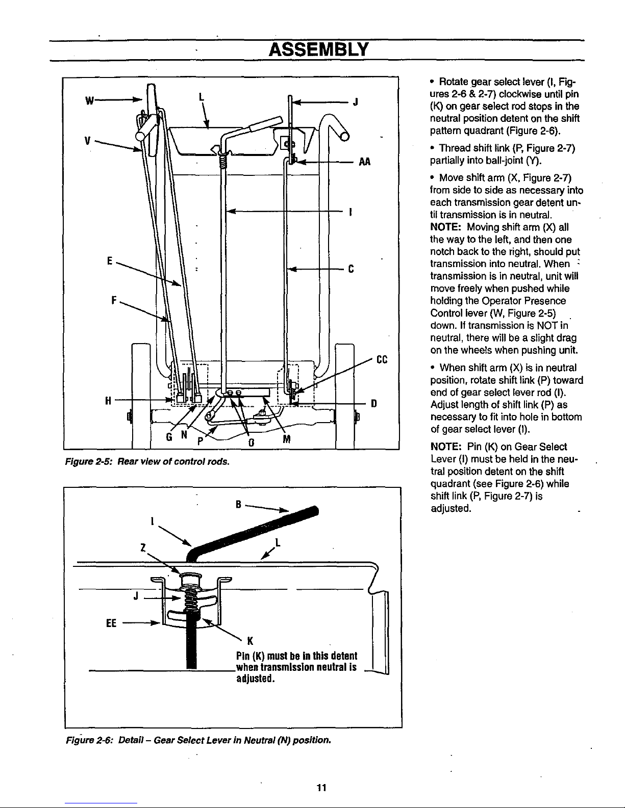
Figure 2-5: Rear view of control rods.
0 M
D
P
Pin(K) mustbe in this detent
whentransmissionneutral is _
adjusted.
• Rotate gear select lever (I, Fig-
ures 2-6 & 2-7) clockwise until pin
(K) on gear select rod stops in the
neutral position detent on the shift
pattern quadrant (Figure 2-6).
• Thread shift link (P, Figure 2-7)
partiallyinto ball-joint (Y).
• Move shift arm (X, Figure 2-7)
from side to side as necessary into
each transmissiongear detent un-
tiltransmission is in neutral.
NOTE: Moving shift arm (X) all
the way to the left, and then one
notch back to the right, shouldput
transmission into neutral. When :
transmission is inneutral, unit will
move freelywhen pushed while
holdingthe Operator Presence
Control lever (W, Figure 2-5)
down. If transmission is NOT in
neutral, there will be a slight drag
on the wheels when pushingunit.
• When shift arm (X) is in neutral
position, rotate shift link (P) toward
end of gear select lever rod (I).
Adjust length of shift link (P) as
necessary to fit into hole in bottom
of gear select lever (I).
NOTE: Pin (K) on Gear Select
Lever (I) must be held in the neu-
tral positiondetent on the shift
quadrant (see Figure 2-6) while
shift link(P, Figure 2-7) is
adjusted.
Figure2-6: Detail - Gear SelectLever in Neutral (N) position.
11
ASSEMBLY
I
I
I
!
I
I
I
I
I
I
I
I
I
!
!
I
!
I
I
!
I
P
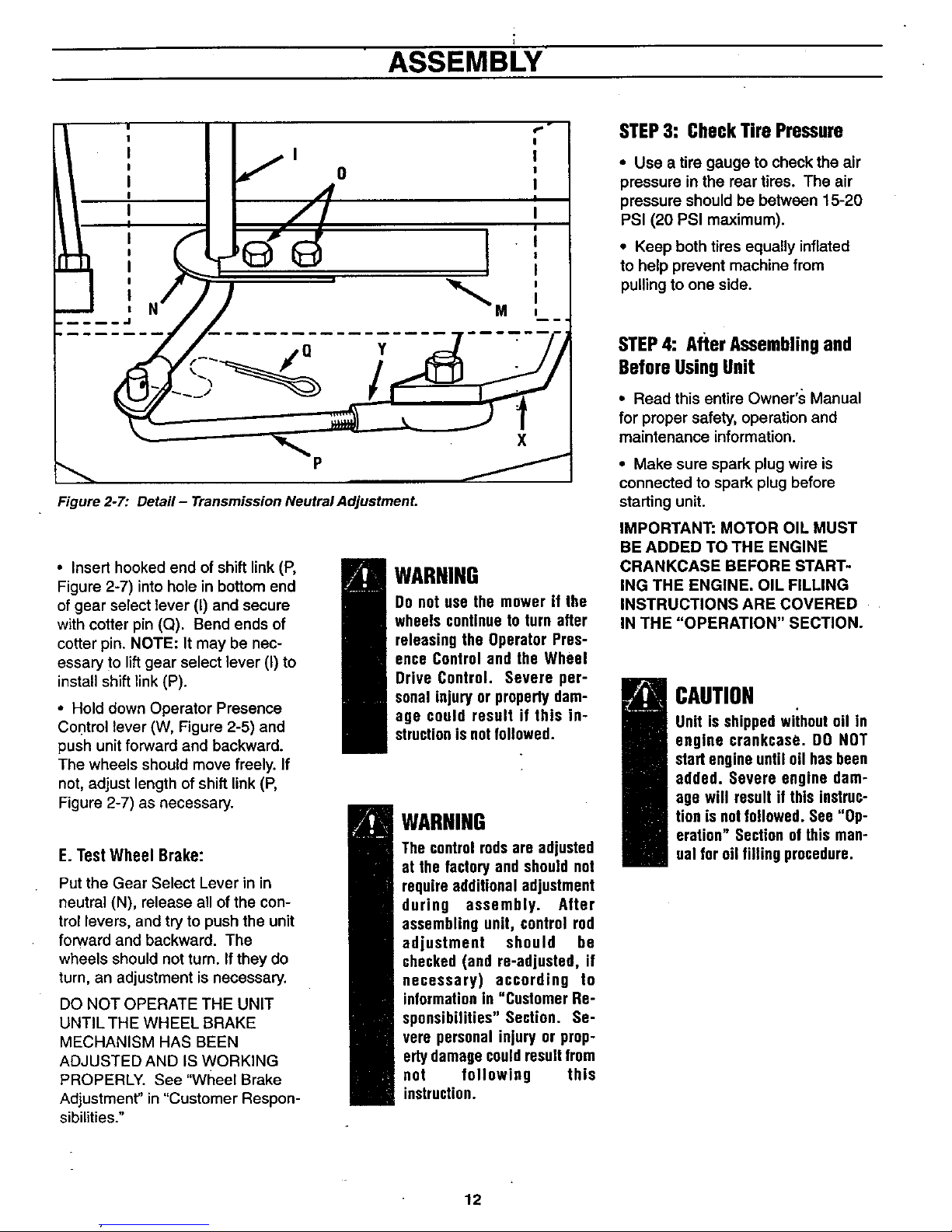
Figure 2-7: Detail- TransmissionNeutralAdjustment.
• Insert hooked end of shift link (P,
Figure 2-7) into hole in bottom end
of gear select lever (I) and secure
with cotter pin (Q). Bend ends of
cotter pin. NOTE: It may be nec-
essary to lift gear select lever (I) to
install shift link (P).
* Hold down Operator Presence
Control lever (W, Figure 2-5) and
push unit forward and backward.
The wheels should move freely. If
not, adjust length of shift link (P,
Figure 2-7) as necessary.
E.TestWheel Brake:
Put the Gear Select Lever in in
neutral (N), release all of the con-
trol levers, and try to push the unit
forward and backward. The
wheels should not turn. if they do
turn, an adjustment is necessary.
DO NOT OPERATE THE UNIT
UNTIL THE WHEEL BRAKE
MECHANISM HAS BEEN
ADJUSTED AND IS WORKING
PROPERLY. See "Wtleel Brake
Adjustment" in "Customer Respon-
sibilities."
WARNING
Do not use the mower if the
wheels continueto turn after
releasing the Operator Pres-
ence Control and the Wheel
Drive Control. Severe per-
sonal injury or property dam-
age could result if this in-
structionis notfollowed.
WARNING
The controlrodsare adjusted
at the factoryand shouldnot
requireadditionaladjustment
during assembly. After
assembling unit, control rod
adjustment should be
checked (and re-adjusted, if
necessary) according to
informationin "Customer Re-
sponsibilities" Section. Se-
vere personal injury or prop-
ertydamagecouldresultfrom
not following this
instruction.
STEP3: CheckTire Pressure
• Use a tire gauge to check the air
pressure in the rear tires. The air
pressure should be between 15-20
PSI (20 PSI maximum).
• Keep both tires equally inflated
to help prevent machine from
pullingto one side.
STEP4: After Assemblingand
BeforeUsingUnit
• Read this entire Owner's Manual
for proper safety, operation and
maintenance information.
• Make sure spark plug wire is
connected to spark plug before
starting unit.
IMPORTANT: MOTOR OIL MUST
BE ADDED TO THE ENGINE
CRANKCASE BEFORE START-
ING THE ENGINE. OIL FILLING
INSTRUCTIONS ARE COVERED
IN THE "OPERATION" SECTION.
CAUTION
Unit is shippedwiihoutoil in
engine crankcase. DO NOT
startengineuntil oil hasbeen
added. Severe engine dam-
age will result if this instruc-
tion isnot followed. See"Op-
eration" Sectionof this man-
ual for oil filling procedure.
12
OPERATION
KNOWYOUREQUIPMENT
READ THIS OWNER'S MANUALAND ALL SAFETY RULES BEFORE OPERATING YOUR EQUIPMENT. Know the
location and function of all features and controls on the equipment. Save this manual for future reference.
MEETS ANSI B71.1 - 1996
SAFETY STANDARD
This machine meets voluntary
safety standard B71.1 - 1996,
which is sponsored by the Outdoor
Power Equipment Institute, Inc.,
and is published by the American
National Standards Institute, Inc.
Operating Symbols
Various symbolsare used on the
mower to indicate control settings
(yourmodel may not have all of the
symbols). These symbols are
shown below with a description of
theirmeaning.
FAST SLOW CHOKE
ENGINE ENGINE ENGINE
STOP START RUN
ENGAGE DISENGAGE
IMPORTANT: The mower is
equipped with a blade-brake-clutch
controlsystem which is designed
to stopthe mower blades within
three (3) seconds after release of
the Operator Presence Control.
This system will stop the blades
but not the engine. Therefore, you
can disengage the blade drive at
anytime without having to stop and
restart the engine. This feature is
particularly useful when you need
to crossgravel drives or rough ter-
rain and you do not want the spin-
ning blades to strike stones or hid-
den obstacles.
WARNING
The blade-brake-clutch con-
trol system should stop the
mowerbladeswithinthree(3)
secondsafter release of the
OperatorPresenceControl.If
the bladesdo notstopwithin
three-(3) seconds,potthe En-
gine Throttle Control in the
STOP position. Disconnect
thesparkplugwire anddonot
operate the mower until the
blade-brake-clutch control
systemhasbeenrepaired_
LOCATIONANDUSEOF
CONTROLS
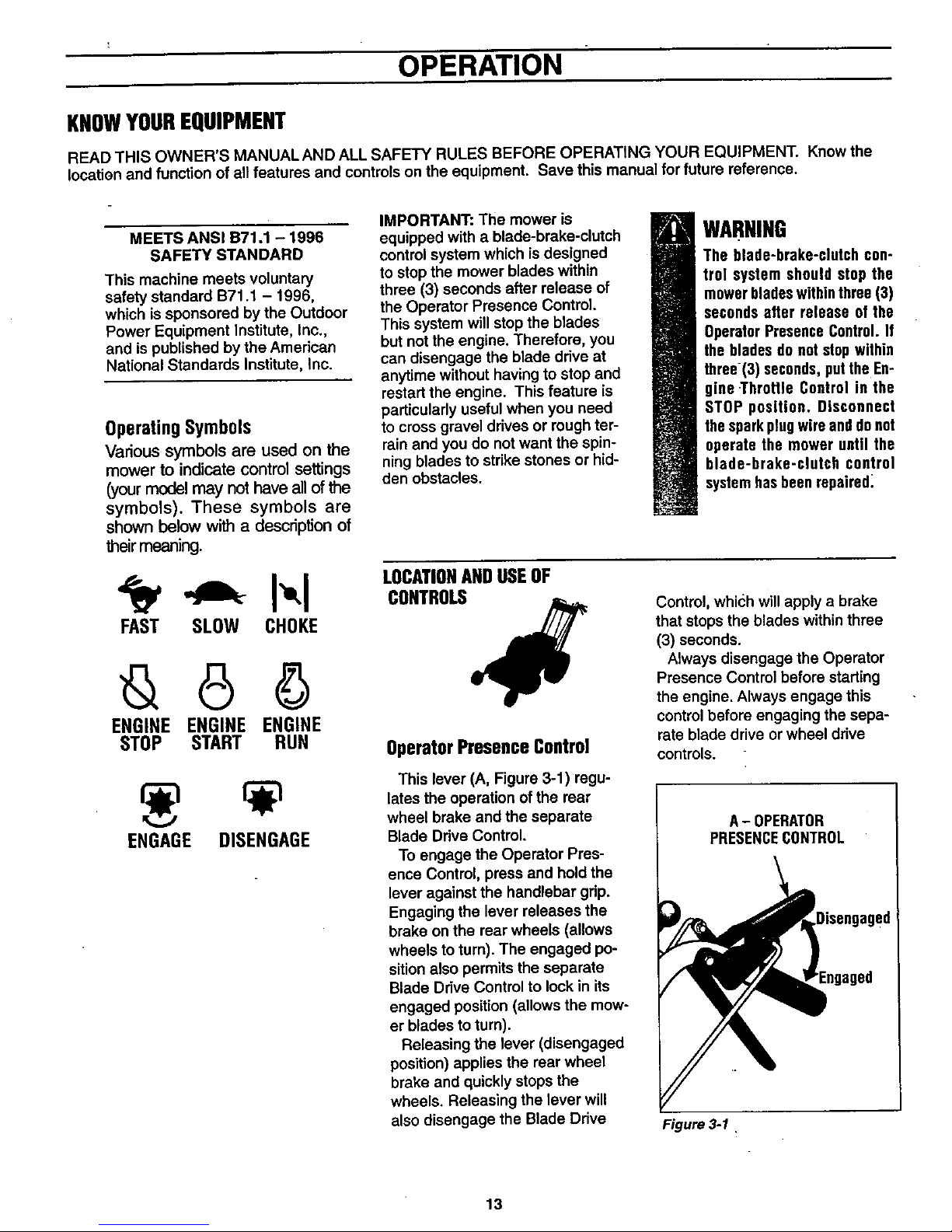
OperatorPresenceControl
This lever (A, Figure 3-1) regu-
lates the operation ofthe rear
wheel brake and the separate
Blade Drive Control.
To engage the Operator Pres-
ence Control, press and hold the
lever against the handlebar grip.
Engaging the lever releases the
brake on the rear wheels (allows
wheels to turn). The engaged po-
sitionalso permits the separate
Blade Drive Control to lock in its
engaged position (allows the mow-
er blades to turn).
Releasing the lever (disengaged
position) applies the rear wheel
brake and quickly stops the
wheels. Releasing the lever will
also disengage the Blade Drive
Control, which will apply a brake
that stops the blades within three
(3) seconds.
Always disengage the Operator
Presence Control before starting
the engine. Always engage this
controlbefore engaging the sepa-
rate blade drive or wheel drive
controls.
A- OPERATOR
PRESENCECONTROL
ed
Figure 3-1 ,
13
OPERATION
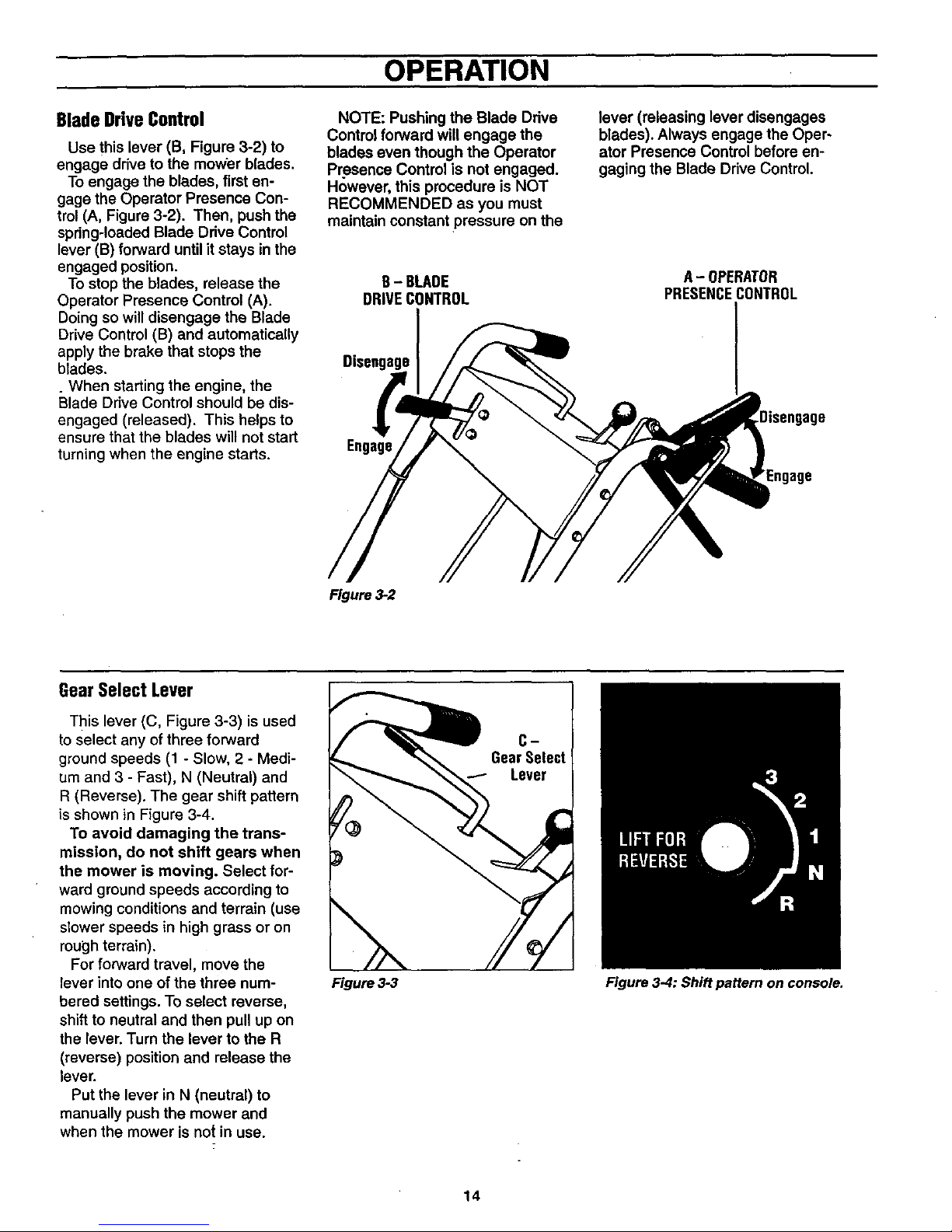
BladeDriveControl
Use this lever (B, Figure 3-2) to
engage drive to the mower blades.
To engage the blades, first en-
gage the Operator Presence Con-
trol (A, Figure 3-2). Then, push the
spring-loaded Blade Drive Control
lever (B) forward until it stays in the
engaged position.
To stop the blades, release the
Operator Presence Control (A).
Doing so will disengage the Blade
Drive Control (B) and automatically
apply the brake that stops the
blades.
_When starting the engine, the
Blade Drive Control should be dis-
engaged (released). This helps to
ensure that the blades will not start
turning when the engine starts.
NOTE: Pushing the Blade Ddve
Control forward will engage the
blades even though the Operator
Presence Control is not engaged.
However, this procedure is NOT
RECOMMENDED as you must
maintain constant pressure on the
B- BLADE
DRIVECONTROL
Disengage
Engage
lever (releasing lever disengages
blades). Always engage the Oper-
ator Presence Control before en-
gaging the Blade Drive Control.
A-OPERATOR
PRESENCECONTROL
Engage
Figure 3-2
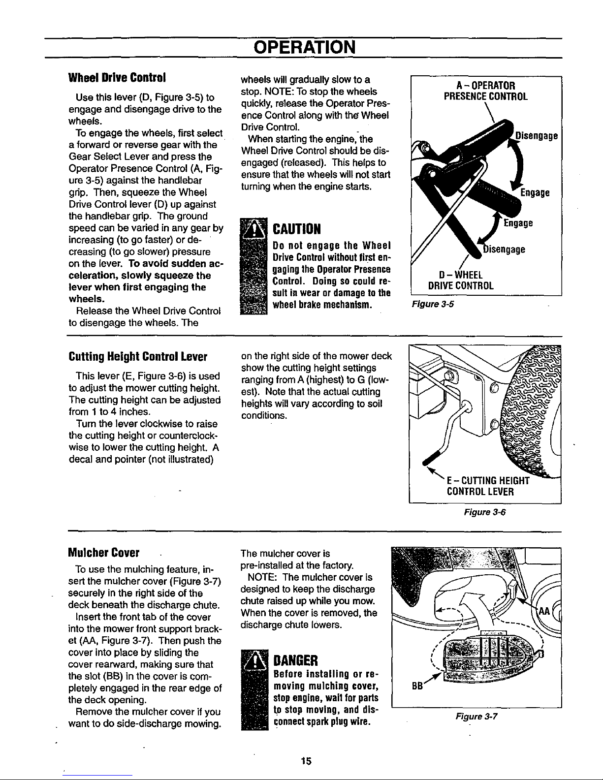
GearSelectLever
This lever (C, Figure 3-3) is used
toselect any of three forward
ground speeds (1 - Slow, 2 - Medi-
um and 3 - Fast), N (Neutral) and
R (Reverse). The gear shift pattern
is shown in Figure 3-4.
To avoid damaging the trans-
mission, do not shift gears when
the mower is moving. Select for-
ward ground speeds according to
mowing conditions and terrain (use
slower speeds in high grass or on
rough terrain).
Forforward travel, move the
lever into one of the three num-
bered settings. To select reverse,
shift to neutral and then pull up on
the lever. Turn the lever to the R
(reverse) position and release the
lever.
Put the lever in N (neutral) to
manually push the mower and
when the mower is not in use.
CD
GearSelect
Lever
Figure 3-3 Figure 3-4: Shift pattern on console.
14
OPERATION
WheelDriveControl
Use this lever (D, Figure 3-6) to
engage and disengage drive to the
wheels.
To engage the wheels, first select
a forward or reverse gear with the
Gear Select Lever and press the
Operator Presence Control (A, Fig-
ure 3-5) against the handlebar
grip. Then, squeeze the Wheel
Drive Control lever (D) up against
the handlebar grip. The ground
speed can be varied in any gear by
increasing (to go faster) or de-
creasing (to go slower) pi'essure
on the lever. To avoid sudden ac-
celeration, slowly squeeze the
lever when first engaging the
wheels.
Release the Wheel Drive Control
to disengage the wheels. The
wheels will gradually slowto a
stop. NOTE: To stopthe wheels
quickly, release the Operator Pres-
ence Control along withthe Wheel
Drive Control.
When startingthe engine,-the
Wheel Drive Control should be dis-
engaged (released). This helps to
ensure thatthe wheels willnotstart
turningwhen the engine starts.
CAUTION
Do not engage the Wheel
DriveControlwithoutfirst en-
gagingthe OperatorPresence
Control. Doingso could re-
sult inwear or damageto the
wheelbrakemechanism.
I A- OPERATOR
PRESENCECONTROL
!isengage
Engage
D- WHEEL
DRIVECONTROL
Figure 3-5
CuttingHeight ControlLever
This lever (E, Figure 3-6) is used
to adjust the mower cutting height.
The cutting height can be adjusted
from 1 to 4 inches.
Turn the lever clockwise to raise
the cutting height or counterclock-
wise to lower the cutting height. A
decal and pointer (not illustrated)
on the rightside of the mower deck
show the cuttingheight settings
ranging from A (highest) to G (low-
est). Note that the actual cutting
heights willvary according to soil
conditions.
MulcherCover
To use the mulching feature, in-
sert the mulcher cover (Figure 3-7)
securely in the right side of the
deck beneath the discharge chute.
Insert the front tab of the cover
into the mower front support brack-
et (AA, Figure 3-7). Then push the
cover intoplace by slidingthe
cover rearward, making sure that
the slot (BB) in the cover is com-
pletely engaged in the rear edge of
the deck opening.
Remove the mulcher cover if you
want to do side-discharge mowing.
The mulcher cover is
pre-installed at the factory.
NOTE: The mulcher cover is
designed to keep the discharge
chute raised up while you mow.
When the cover is removed, the
discharge chute lowers.
i DANGER
Before installing or re-
moving mulching cover,
stopengine,wait for parts
tD stop moving, and dis-
connectsparkplugwire.
Figure 3-7
15
OPERATION
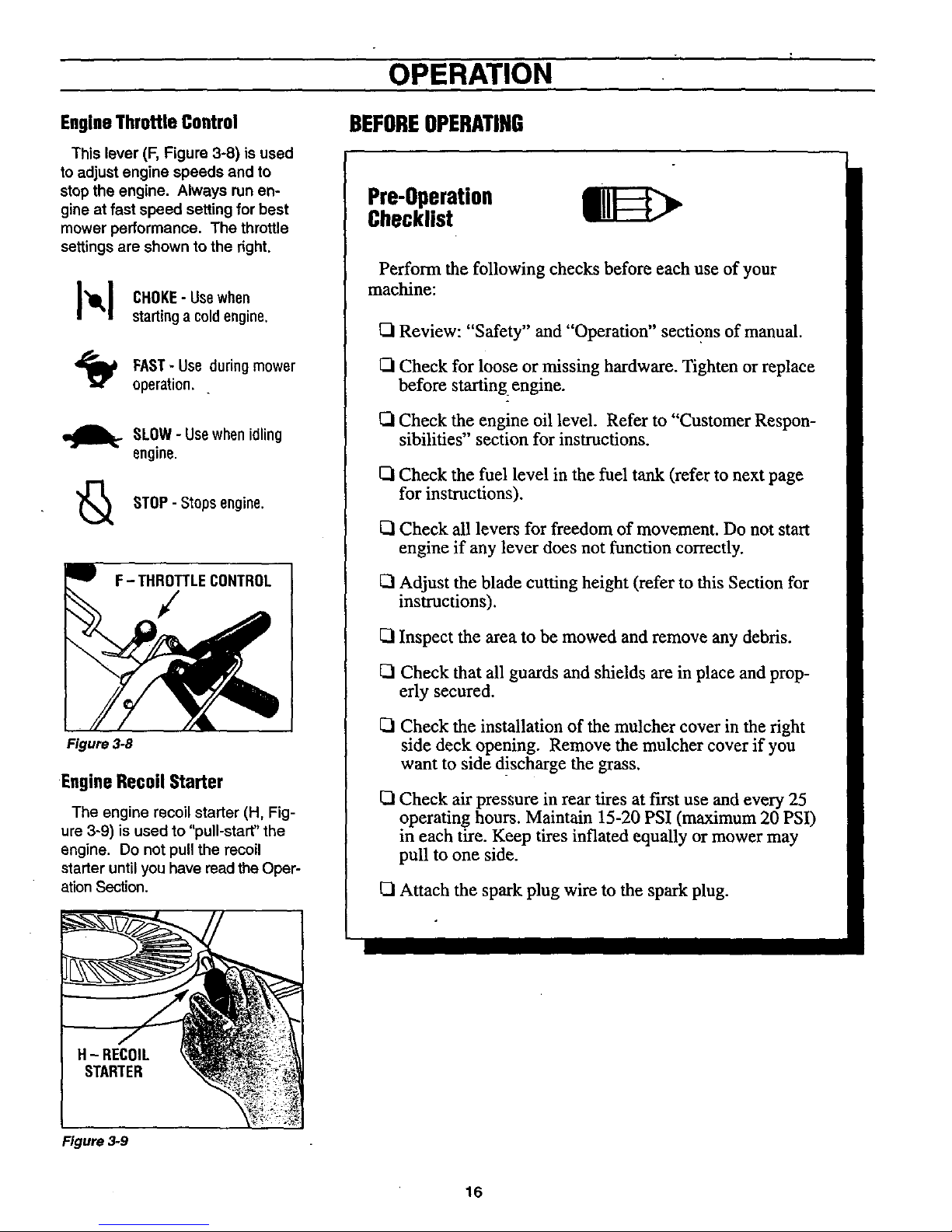
EngineThrottle Control
This lever (F, Figure 3-8) is used
to adjust engine speeds and to
stop the engine. Always run en-
gine at fast speed setting for best
mower performance. The throttle
settings are shown to the right.
]_1_1 CHOKE- Usewhen
startinga coldengine.
FAST- Use duringmower
operation. _
SLOW- Usewhenidling
engine.
'_ STOP- Stopsengine.
F- THRoJiLECONTROL
J
Figure 3-8
EngineRecoilStarter
The engine recoil starter (H, Fig-
ure 3-9) is used to "pull-start"the
engine. Do not pull the recoil
starter until you have read the Oper-
ation Section.
BEFOREOPERATING
Pre-Operation
Checklist
Perform the following checks before each use of your
machine:
ISlReview: "Safety" and "Operation" sections of manual.
Q Check for loose or missing hardware. Tighten or replace
before starting engine.
Q Check the engine oil level. Refer to "Customer Respon-
sibilities" section for instructions.
ISICheck the fuel level in the fuel tank (refer to next page
for instructions).
Q Check all levers for freedom of movement. Do not start
engine if any lever does not function correctly.
Adjust the blade cutting height (refer to this Section for
instructions).
Inspect the area to be mowed and remove any debris.
Check that all guards and shields are in place and prop-
erly secured.
_1 Check the installation of the mulcher cover in the right
side deck opening. Remove the mulcher cover if you
want to side d!scharge the grass.
I_1Check air pressure in rear tires at first use and every 25
operating hours. Maintain 15-20 PSI (maximum 20 PSI)
in each tire. Keep tires inflated equally or mower may
pull to one side.
ISIAttach the spark plug wire to the spark plug.
H- RECOIL
STARTER
Figure 3-9
16
 Loading...