

Page 1
OWNER'S
MANUAL
MODEL NO.
934.55125590
CONTENTS
IMPORTANT SAFEGUARDS .................. 2
PRECAUTIONS ............................ 4
FEATURES ................................ 5
SUPPLIED ACCESSORIES ................... 6
OPERATING CONTROLS AND FUNCTIONS ..... 6
REMOTE CONTROL OPERATION ............. 8
ANTENNA]CABLE SYSTEM CONNECTIONS .... 10
CONTROLLING VCR INPUT & OUTPUT ....... 13
CHANNEL MEMORY PROGRAMMING ......... 14
SETTING THE CLOCK ...................... 16
TO CHANGE THE LANGUAGE ............... 17
VIEWING AND RECORDING THE SAME
PROGRAM ............................... 18
RECORDING ONE PROGRAM WHILE
VIEWING ANOTHER ....................... 19
AUTOMATIC TIMER RECORDING ............ 19
QUICK SET PROGRAM ..................... 22
INDEX SEARCH .......................... 24
TIME SEARCH ............................ 25
BLANK SEARCH .......................... 26
SETTING THE REMAINING TIME ............. 27
JUST-IN TIME RECORDING ................. 28
OTR (ONE ]:OUCH RECORDING) ............ 29
MONITORING RECORDING ................. 29
PLAYBACK ............................... 30
AUTO REPEAT PLAYBACK .................. 30
RENTAL PLAY ............................ 31
COUNTER MEMORY ....................... 32
SPECIAL FEATURES ....................... 33
VIDEO CASSETTE TAPE .................... 34
TROUBLESHOOTING GUIDE ................ 35
MAINTENANCE ........................... 36
SPECIFICATIONS ......................... 37
VIDEO
CASSETTE
RECORDER
Record the Model Number and Serial Num-
ber of your VCR. The Model Number and
the Serial number are on the rear panel.
Model No.
Serial No.
Keepthesenumbers for future use.
Page 2
TO REDUCE THE RISK OF FIRE OR ELECTRIC SHOCK, DO NOT EXPOSE THIS APPLIANCE TO RAIN OR
MOISTURE.
WARNING: ]
i
THIS SYMBOL INDICATES THAT DAN-
GEROUS VOLTAGE CONSTITUTING A
RISK OF ELECTRIC SHOCK IS PRESENT
WITHIN THIS UNIT.
lSK OFE--
SHOCK, DO NOT REMOVE COVER (OR BACK)F_O
USER SERVICEABLE PARTS INSIDE.
SERVICING TO QUALIFIED SERVICE PERSON-
NEL.
The important note is located on therearof the cabinet.
THIS SYMBOL INDICATES THAT
THERE ARE IMPORTANT OPERATING
AND MAINTENANCE INSTRUCTIONS
IN THE LITERATURE ACCOMPANYING
THE APPLIANCE.
IMPORTANT SAFEGUARDS
1. Read instructions-All the safety and operating instruc-
tions should be read before the appliance is operated.
2. Retain Instructions-The safety and operating instruc-
tions should be retained for future reference.
3. Heed Warnings-All warnings on the appliance and in the
operating instructions should be adhered to.
4. Follow Instructions-All operating and use instructions
shoul0 be followed.
5. Cleaning-Unplug this video product from the wall outlet
before cleaning. Do not use liquid cleaners or aerosol
cleaners. Use a damp cloth for cleaning.
EXCEPTION: A product that is meant for uninter-
rupted service and, that for some specific reason, such as
the possibility of the loss of an authorization code for a
CATV converter, is not intended to be unplugged by the
user for cleaning or any other purpose, may exclude the
reference to unplugging the appliance in the cleaning
description otherwise required in item 5.
6. Attachments-Do not use attachments not recommended by
the video product manufacturer as they may cause hazards.
7. Water and Moisture-Do not use this video product near
water, for example, near a bath tub, wash bowl, kitchen
sink, or laundry tub, in a wet basement, or near a swim-
ming pool, and the like.
8. Accessories-Do not place this video product on an unsta-
ble cart, stand, tripod, bracket, or table. The video product
may fall, causing serious injury to a child or adult, and
serious damage to the appliance. Use only with a cart,
stand, tripod, bracket, or table recommended by the manu-
facturer, or sold with the video _RrAatEcARrWAR_
product. Any mounting of the ap- Isy,r_ p,ov_o_byRErAC_
pliance should follow the manu-
facturer's instructions and should
use amounting accessory recom-
mended by the manufacturer. An
appliance and cart combination
should be moved with care.
Quick stops, excessive force, and
uneven surfaces may cause the
S3125A
appliance and cart combination to overturn.
9.
Ventilation-Slots and openings in the cabinet are pro-
vided for ventilation and to ensure reliable operation of
the video product and to protect itfrom overheating, and
these openings must not be blocked or covered. The
openings should never be blocked by placing the video
product on a bed, sofa, rug, or other similar surface. This
video product should notbe placed inabuilt-in installation
such as a bookcase or rack unless proper ventilation is
provided or the manufacturer's instructions have been
adhered to.
10. Power Sources-This video product should be operated
only from the type of power source indicated on the
marking label. If you are not sure of the type of power
supply to your home, consult your appliance dealer or
local power company. For products intended to operate
from battery power, or other sources, refer to the operating
instructions.
11. Grounding or Polarization-This video product is
equipped with a polarized alternating--currentline plug (a
plug having one blade wider thanthe other). This plug will
fitinto thepower outlet only one way. This isa safety feature.
If you are unable to insertthe plug fully into the outlet, try
reversing the plug. If the plug should still fail to fit, contact
yourelectrician to replace yourobsolete outlet. Do not defeat
thesafety purpose of the polarized plug.
12. Power Cord Protection-Power supply cords should be
routed so that they are not likely to be walked on or
pinched by items placed upon or against them, paying
particular attention to cords at plugs, convenience recep-
tacles, and the point where they exit from the appliance.
13. Outdoor Antenna Grounding-If an outside antenna or
cable system is connected to the video product, be surethe
antenna or cable system is grounded so as toprovide some
protection against voltage surges and built-up static
charges. Article 810 of the National Electrical Code,
ANSI/NFPA No. 70, provides information with regard to
proper grounding of the mastand supportingslruclure,
grounding of the lead-in wire to an antenna discharge unit,
size of grounding conductors, location of antenna-dis-
-2-
Page 3
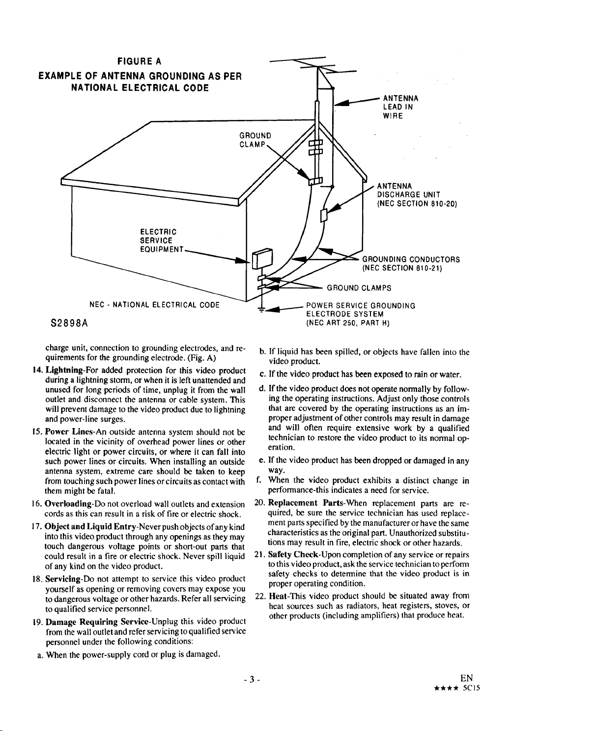
FIGURE A
EXAMPLE OF ANTENNA GROUNDING AS PER
NATIONAL ELECTRICAL CODE
ELECTRIC
SERVICE
EQUIPM
NEC- NATIONALELECTRICALCODE
$2898A
ANTENNA
LEAD IN
WIRE
GROUND
DISCHARGE UNIT
(NEC SECTION 810-20
GROUNDING CONDUCTORS
(NEC SECTION 8t0-2t)
GROUND CLAMPS
POWER SERVICE GROUNDING
ELECTRODE SYSTEM
(NEC ART 250, PART H)
charge unit, connection to grounding electrodes, and re-
quirements for the grounding electrode. (Fig. A)
14. Lightning-For added protection for this video product
during a lightning storm, or when it is left unattended and
unused for long periods of time, unplug it from the wall
outlet and disconnect the antenna or cable system. This
will prevent damage to the video product due to lightning
and power-line surges.
15. Power Lines-An outside antenna system should not be
located in the vicinity of overhead power lines or other
electric light or power circuits, or where it can fall into
such power lines or circuits. When installing an outside
antenna system, extreme care should be taken to keep
from touching such power lines or circuits as contact with
them might be fatal.
16. Overloading-Do not overload wall outlets and extension
cords as this can result in a risk of fire or electric shock.
I7. Object and Liquid Entry-Never push objects ofany kind
into this video product through any openings as they may
touch dangerous voltage points or short-out parts that
could result in a fire or electric shock. Never spill liquid
of any kind on the video product.
18. Servlcing-Do not attempt to service this video product
yourself as opening or removing covers may expose you
to dangerous voltage or other hazards. Refer all servicing
to qualified service personnel.
19. Damage Requiring Service-Unplug this video product
from the wall outlet and refer serv icing to qualified service
personnel under the following conditions:
a. When the power-supply cord or plug is damaged.
b. If liquid has been spilled, or objects have fallen into the
video product.
c. If the video product has been exposed to rain or water.
d°
If the video product does not operate normally by follow-
ing the operating instructions. Adjust only those controls
that are covered by the operating instructions as an im-
proper adjustment of other controls may result in damage
and will often require extensive work by a qualified
technician to restore the video product to its normal op-
eration.
e. If the video product has been dropped or damaged in any
way.
f. When the video product exhibits a distinct change in
performance-this indicates a need for service.
20. Replacement Parts-When replacement parts are re-
quired, be sure the service technician has used replace-
ment parts specified by the manufacturer or have the same
characteristics as the original part. Unauthorized substitu-
tions may result in fire, electric shock or other hazards.
21. Safety Check-Upon completion of any service or repairs
to this video product, ask the service technician to perform
safety checks to determine that the video product is in
proper operating condition.
22. Heat-This video product should be situated away from
heat sources such as radiators, heat registers, stoves, or
other products (including amplifiers) that produce heat.
- 3 - EN
-/t, _t, 5C15
Page 4

PRECAUTIONS
I[oIe_YU(O_
For safe operation and satisfactory performance of your
VCR, keep the following in mind when selecting a
place for its installation:
• Shield it from direct sunlight and keep it away from
sources of intense heat.
• Avoid dusty or humid places.
• Avoid places with insufficient ventilation for proper
heat dissipation. Do not block the ventilation holes
at the top and bottom of the VCR. Do not place the
unit on a carpet because this will block the ventila-
Do not handle the power cord with wet hands.
Do not pull on the power cord when disconnecting it
from AC wall outlet. Grasp it by the plug.
If, by accident, water isspilled on your VCR, unplug
the power cord immediately and take the unit to a
Sears Authorized Service Center for servicing.
Do not put your fingers or objects into the VCR cas-
sette holder.
Do not place anything directly on top of the VCR.
tion holes.
• Install unit in a horizontal position.
• Avoid locations subject to strong vibration.
• Do not place the VCR near strong magnetic fields.
• Do not move the unit from a cold to a hot place or
vice versa.
Moisture condensation may occur insidc the unit when
it ismoved from a cold place to a warm place, or after
heating a cold room or under conditions of high humid-
ity. Do not use the VCR until its inside is dry.
FCC WARNING- This equipment may generate or use radio frequency energy. Changes or modifications
to this equipment may cause harmful interference unless the modifications are expressly approved in the
instruction manual. The user could lose the authority to operate this equipment if an unauthorized change
or modification is made.
IMPORTANT COPYRIGHT INFORMATION
Unauthorized recording or use of broadcast television programming, video tape, film or other copyrighted
material may violate applicable copyright laws. We assume no responsibility for the unauthorized duplication,
use or other acts which infringe upon the rights of copyright owners.
The serial number of this product may be found on the back of the VCR. No others have the same serial number
as yours. You should record the number and other vital information here and retain this book as a permanent record
of your purchase to aid identification in case of theft.
Date of Purchase
Dealer Purchased from
Dealer Address
Dealer Phone No.
Model No.
Serial No.
- 4 - EN
***** 5CI6
Page 5
FEATURES
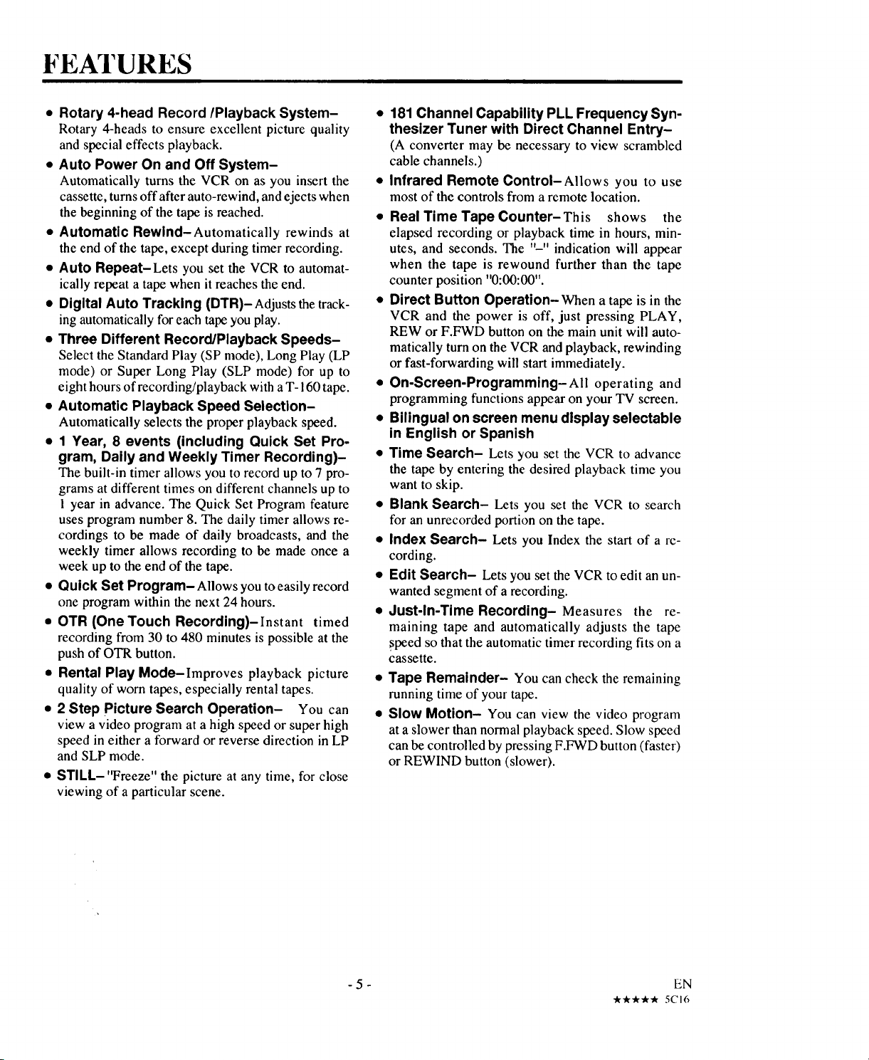
• Rotary 4-head Record/Playback System-
Rotary 4-heads to ensure excellent picture quality
and special effects playback.
• Auto Power On and Off System-
Automatically turns the VCR on as you insert the
cassette, turns off after auto-rewind, and ejects when
the beginning of the tape is reached.
• Automatic Rewind-Automatically rewinds at
the end of the tape, except during timer recording.
• Auto Repeat-Lets you set the VCR to automat-
ically repeat a tape when it reaches the end.
• Digital Auto Tracking (DTR)- Adjuststhetrack-
ing automatically for eachtapeyouplay.
• Three Different Record/Playback Speeds-
Select the Standard Play (SP mode), Long Play (LP
mode) or Super Long Play (SLP mode) for up to
eight hours of recording/playback with a T- 160 tape.
• Automatic Playback Speed Selection-
Automatically selects the proper playback speed.
• 1 Year, 8 events (including Quick Set Pro-
gram, Daily and Weekly Timer Recording)-
The built-in timer allows you torecord upto7 pro-
grams at different times on different channels up to
! year in advance. The Quick Set Program feature
uses program number 8. The daily timer allows re-
cordings to be made of daily broadcasts, and the
weekly timer allows recording to be made once a
week up to the end of the tape.
• Quick Set Program- Allows you to easily record
one program within the next 24 hours.
• OTR (One Touch Recording)-Instant timed
recording from 30 to 480 minutes is possible at the
push of OTR button.
• Rental Play Mode-Improves playback picture
quality of worn tapes, especially rental tapes.
• 2 Step Picture Search Operation- You can
view a video program at a high speed or super high
speed in either a forward or reverse direction in LP
and SLP mode.
• STILL- "Freeze" the picture at any time, for close
viewing of a particular scene.
• 181 Channel Capability PLL Frequency Syn-
thesizer Tuner with Direct Channel Entry-
(A converter may be necessary to view scrambled
cable channels.)
• Infrared Remote Control-Allows you to use
mostof the controls from a remote location.
• Real Time Tape Counter-This shows the
elapsed recording or playback time in hours, min-
utes, and seconds. The "-" indication will appear
when the tape is rewound further than the tape
counter position "0:00:00".
• Direct Button Operation-When a tape is in the
VCR and the power is off, just pressing PLAY,
REW or F.FWD button on the main unit will auto-
matically turn on the VCR and playback, rewinding
or fast-forwarding will start immediately.
• On-Screen-Programming-All operating and
programming functions appear on your TV screen.
• Bilingual on screen menu display selectable
in English or Spanish
• Time Search- Lets you set the VCR to advance
the tape by entering the desired playback time you
want to skip.
• Blank Search- Lets you set the VCR to search
for an unrecorded portion on the tape.
• Index Search- Lets you Index the start of a re-
cording.
• Edit Search- Lets you set the VCR to edit an un-
wanted segment of a recording.
• Just-In-Time Recording- Measures the re-
maining tape and automatically adjusts the tape
speed so that the automatic timer recording fits on a
cassette.
Tape Remainder- You can check the remaining
running time of your tape.
Slow Motion- You can view the video program
at a slower than normal playback speed. Slow speed
can be controlled by pressing F.FWD button (faster)
or REWIND button (slower).
-5- EN
_ _-lk 5CI6
Page 6
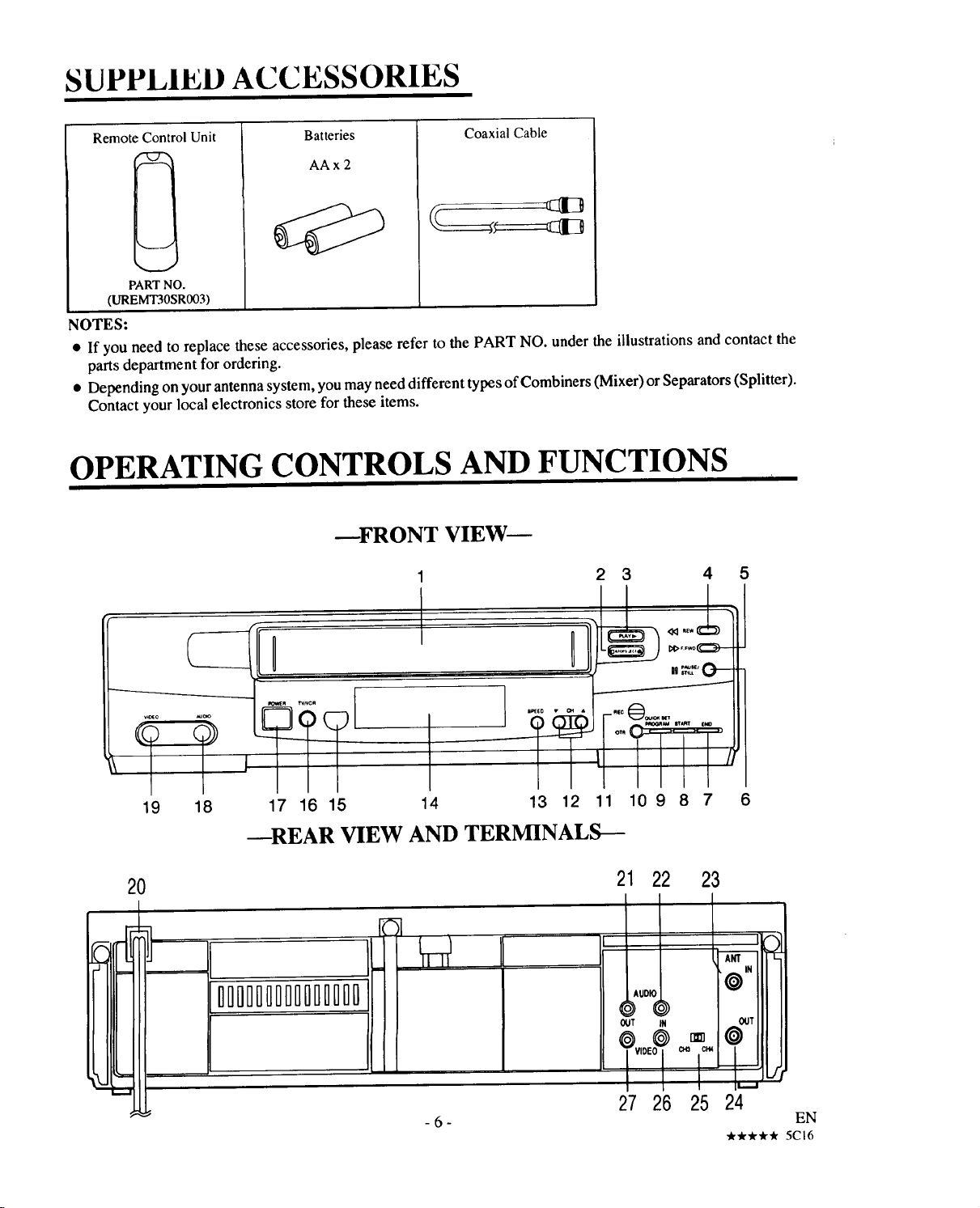
SUPPLIED ACCESSORIES
Remote 2ontrolUnit
Batteries
AAx 2
Coaxial Cable
II
PART NO.
(UREMT30SR003)
NOTES:
• If you need to replace these accessories, please refer to the PART NO. under the illustrations and contact the
parts department for ordering.
• Depending on your antenna system, you may need different types of Combiners (Mixer) or Separators (Splitter).
Contact your local electronics store for these items.
OPERATING CONTROLS AND FUNCTIONS
--FRONT VIEW--
5
19 18 17 16 15 14 13 12 11 10 9 8 7
--REAR VIEW AND TERMINALS---
20
|l
I
IIIIIIIIIIIIIII
21 22 23
AIDIO
OUT IN OUT
6
0"
] 1 I 1
-6-
27 26 25 24
EN
***** 5CI6
Page 7
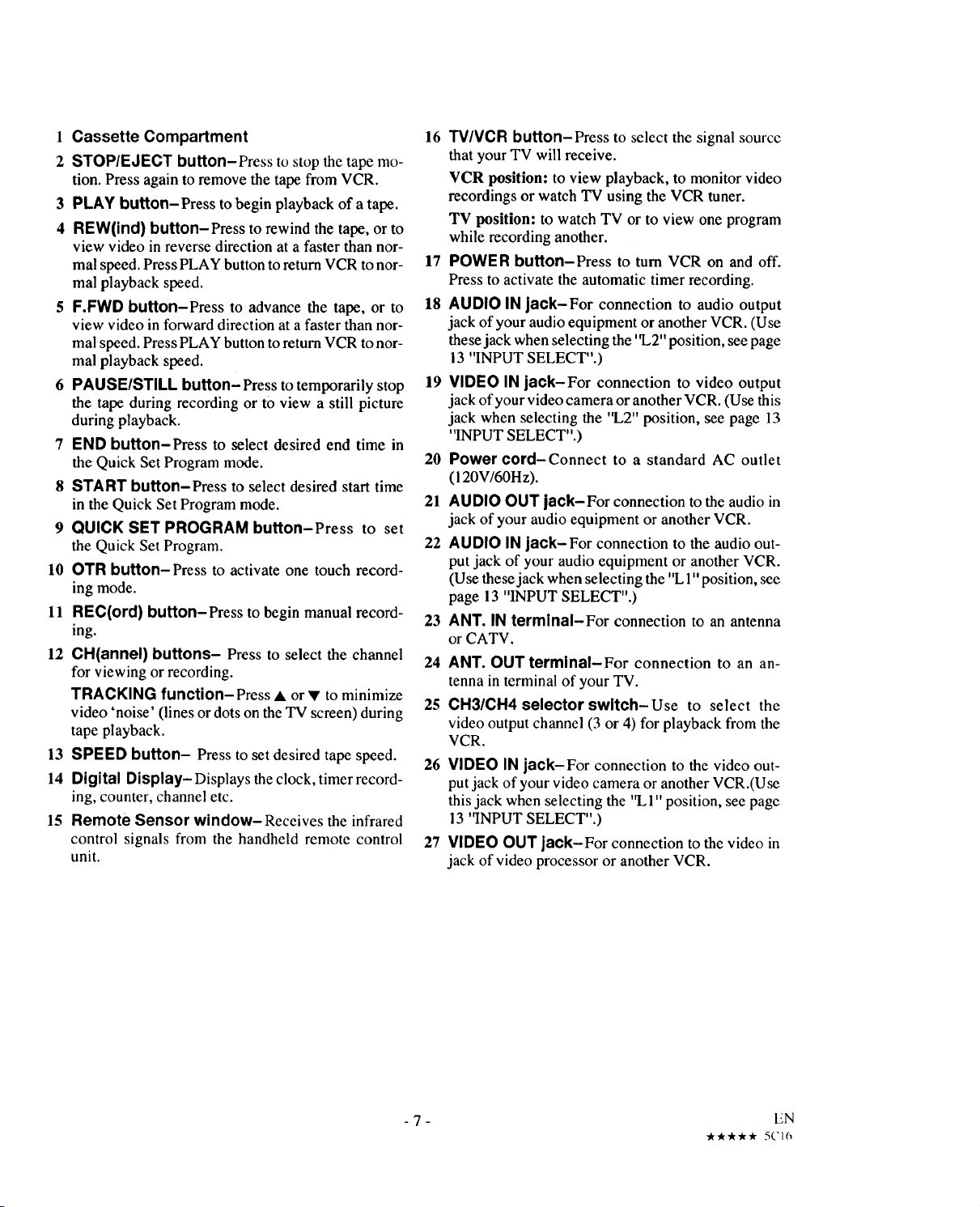
1 Cassette Compartment
2 STOP/EJECT button-Press to stopthe tapemo-
tion. Pressagaintoremovethetapefrom VCR.
3 PLAY button-Press to begin playbackof a tape.
4 REW(ind) button-Press torewind thetape,or to
view videoin reversedirection at a faster thannor-
malspeed.PressPLAY button toreturn VCR tonor-
mal playback speed.
5 F.FWD button-Press to advance the tape, or to
view video in forward direction at a faster than nor-
mal speed. Press PLAY button toreturn VCR to nor-
mal playback speed.
6 PAUSE/STILL button- Press to temporarily stop
the tapeduring recordingor to view a still picture
during playback.
7 END button-Press to select desired end time in
the Quick Set Program mode.
8 START button-Press to select desired start time
in the Quick Set Program mode.
9 QUICK SET PROGRAM button-Press to set
theQuick Set Program.
10 OTR button-Press to activateone touchrecord-
ing mode.
11 REC(ord) button-Press tobeginmanual record-
ing.
12 CH(annel) buttons- Pressto select the channel
for viewingor recording.
TRACKING function-Press • or • tominimize
video'noise' (linesordotsontheTV screen)during
tape playback.
13 SPEED button- Press to set desired tape speed.
14 Digital Display- Displays the clock, timer record-
ing, counter, channel etc.
15 Remote Sensor window-Receives the infrared
control signals from the handheld remote control
unit.
16 TV/VCR button-Press to select the signal source
that your TV will receive.
VCR position: to view playback, to monitor video
recordings or watch TV using the VCR tuner.
TV position: to watch TV or to view one program
while recording another.
17 POWER button-Press to turn VCR on and off.
Press to activate the automatic timer recording.
18 AUDIO IN jack-For connection to audio output
jack of your audio equipment or another VCR. (Use
these jack when selecting the '1.,2"position, see page
13 "INPUT SELECT".)
19 VIDEO IN jack-For connection to video output
jack of your video camera or another VCR. (Use this
jack when selecting the "L2" position, see page 13
"INPUT SELECT".)
20 Power cord-Connect to a standard AC outlet
(120V/60H z).
21 AUDIO OUT jack-For connection to the audioin
jack of your audioequipment or anotherVCR.
22 AUDIO IN jack-For connection to the audio out-
put jack of your audioequipment or another VCR.
(Use these jack when selecting the "L1"position, see
page 13 "INPUT SELECT".)
23 ANT. IN terminal-For connection to an antenna
or CATV.
24 ANT. OUT terminal-For connection to an an-
tenna in terminal of your TV.
25 CH3/CH4 selector switch-Use to select the
video output channel (3 or 4) for playback from the
VCR.
26 VIDEO IN jack-For connection to the video out-
put jack of your video camera or another VCR.(Use
this jack when selecting the '%1" position, see page
13 "INPUT SELECT".)
27 VIDEO OUT jack-For connection tothe video in
jack of video processoror anotherVCR.
- 7 - EN
"k "A""lk_" * 5('16
Page 8
REMOTE CONTROL OPERATION
You can operate most of your VCR's functions from the Remote Control (included). The buttons on the Remote
Control have the same functions as the corresponding buttons on the VCR.
! ![0,%,m mu:ia a [o]u u m
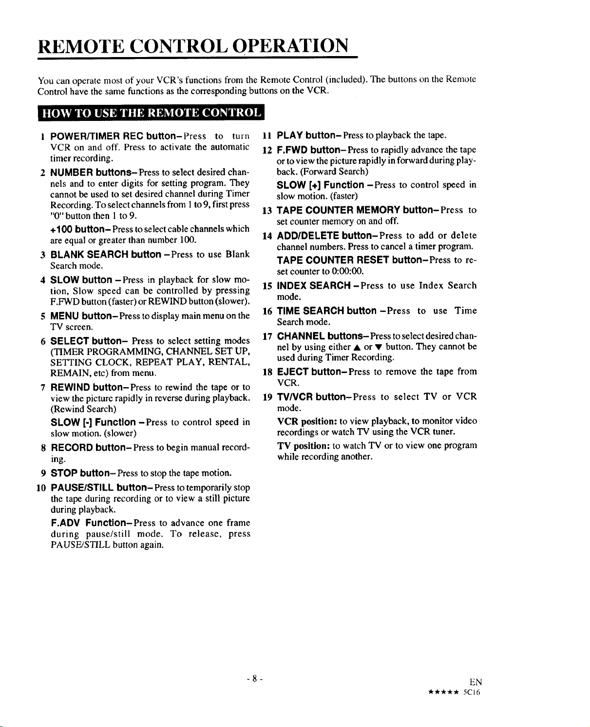
1 POWER/TIMER REC button-Press to turn
VCR on and off. Press to activate the automatic
timer recording.
2 NUMBER buttons-Press to select desired chan-
nels and to enter digits for setting program. They
cannot be used to set desired channel during Timer
Recording. To select channels from 1to 9, first press
"0"button then 1 to 9.
+100 button- Press to select cable channels which
are equal or greater than number 100.
3 BLANK SEARCH button -Press to use Blank
Search mode.
4 SLOW button -Press in playback for slow mo-
tion, Slow speed can be controlled by pressing
F.FWD button (faster) or REWIND button (slower).
5 MENU button-Press to display main menu on the
TV screen.
6 SELECT button- Press to select setting modes
(TIMER PROGRAMMING, CHANNEL SET UP,
SETTING CLOCK, REPEAT PLAY, RENTAL,
REMAIN, etc) from menu.
7 REWIND button-Press to rewind the tape or to
view the picture rapidly inreverse during playback.
(Rewind Search)
SLOW [-] Function-Press to control speed in
slow motion. (slower)
8 RECORD button-Press to begin manual record-
ing.
9 STOP button-Press to stop the tape motion.
10 PAUSE/STILL button-Press to temporarily stop
the tape during recording or to view a still picture
during playback.
F.ADV Function-Press to advance one frame
during pause/still mode. To release, press
PAUSE/STILL button again.
11 PLAY button- Press to playback the tape.
12 F.FWD button-Press to rapidly advance the tape
or to view the picture rapidly in forward during play-
back. (Forward Search)
SLOW [+] Function -Press to control speed in
slow motion. (faster)
13 TAPE COUNTER MEMORY button-Press to
setcounter memoryon andoff.
14 ADD/DELETE button-Press to add or delete
channelnumbers.Presstocancela timerprogram.
TAPE COUNTER RESET button-Press to re-
setcounterto0:00:00.
15 INDEX SEARCH-Press to use Index Search
mode.
16 TIME SEARCH button-Press to use Time
Search mode.
17 CHANNEL buttons-Press to select desired chan-
nel by using either • or • button. They cannot be
used during Timer Recording.
18 EJECT button-Press to remove the tape from
VCR.
19 TV/VCR button-Press to select TV or VCR
mode.
VCR position: to view playback, to monitor video
recordings or watch TV using the VCR tuner.
TV position: to watch TV or to view one program
while recording another.
-8-
EN
_-_r "1__ _r 5CI6
Page 9
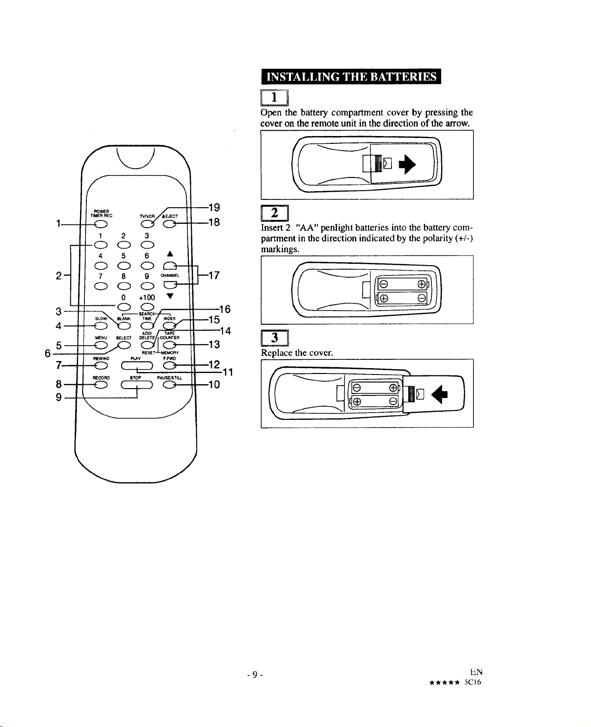
• I_k'JlIt*;1IIIIIII_[ltll Hi I De;y;11Ii il DIq IP[,,,1
Open the battery compartment cover by pressing the
cover on the remote unit in the direction of the arrow.
@HN_NEL
MENU SELECT
RE.NO PLAY F.FWD
PAUSEJ_TILL
9
8
6
5
4
3
r-rl
Insert 2 "AA" penlight batteries into the battery com-
partment in the direction indicated by the polarity (+/-)
markings.
Fyq
Replace the cover.
1
0
- 9 - EN
****'_ 5CI6
Page 10
ANTENNMCABLE SYSTEM CONNECTIONS
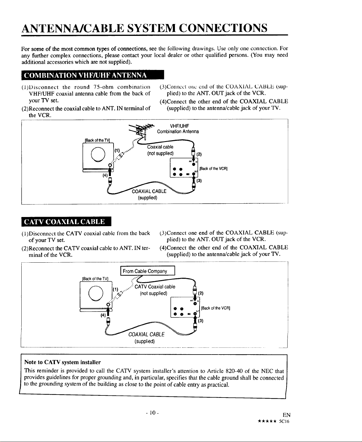
For some of the most common types of connections, see the following drawings. Use only one connection. For
any further complex connections, please contact your local dealer or other qualified persons. (You may need
additional accessories which are not supplied).
L'i{i_t Ik_l _][I_LII | I I ,_-_ii_l_,l_,r;!
(l)Disconnect the round 75-ohm combination
VHF/UHF coaxial antenna cable from the back of
your TV set.
(2)Reconnect the coaxial cable to ANT. IN terminal of
the VCR.
[Backof the "IV] :.,,,._:r u
I 1 ,,,'_: ""--'_xial cable t_
()_;) ..... (nolsupplied) _. (2)
(,)' I. • - €1
'" 131
L =xj
(supplied)
[1_¥ IkvJ[KOT_Ik'qV,.IIIEV.'I HB1
(l)Disconnect the CATV coaxial cable from the back
of your TV set.
(2)Reconnect the CATV coaxial cable to ANT. IN ter-
minal of the VCR.
(3)Connect oi_cend of the COAXIAL CABLE (,sup-
plied) to the ANT. OUT jack of the VCR.
(4)Connect the other end of the COAXIAL CABLE
(supplied) to the antenna/cable jack of your TV.
VHF/UHF
Combination Antenna
(,3)Connect one end of the COAXIAL CABLE (sup-
plied) to the ANT. OUT jack of the VCR.
(4)Connect the other end of the COAXIAL CABLE
(supplied) to the antenna/cable jack of your TV.
IFromCableCompany I
[Back ofthe TV_J :,°,"_"
I...... i::C_al cable t_
(, ) It' _,_;_.... (notsupplied) _ (2)
(,)' I" - "
131
(supplied)
Note to CATV system installer
This reminder is provided to call the CATV system installer's attention to Article 820-40 of the NEC that
provides guidelines for proper grounding and, in particular, specifies that the cable ground shall be connected
to the grounding system of the building as close to the point of cable entry as practical.
-10-
"***** 5C16
EN
!
i
Page 11
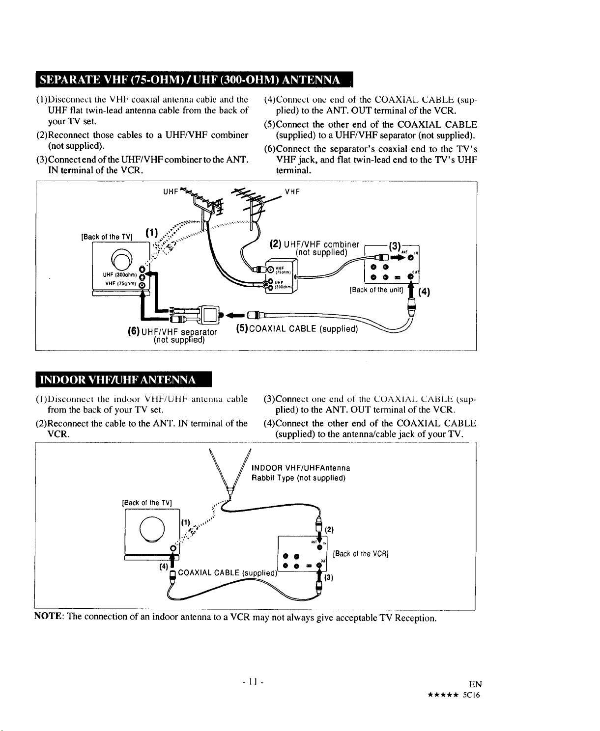
(l)Disconncct the VHF coaxial amcnna cable and the
UHF flat twin-lead antenna cable from the back of
your "IV set.
(2)Reconnect those cables to a UHF/VHF combiner
(not supplied).
(3)Connect end of the UHF/VHF combiner to the ANT.
IN terminal of the VCR.
[Backof the TV]
©
UHF (300ohm)
VHF (75ohm} O
(6) UHF/VHFseparator
(not supplied)
_O]RLglP#___
(4)Connect onc end of the COAXIAL CABLE (sup-
plied) to the ANT. OUT terminal of the VCR.
(5)Connect the other end of the COAXIAL CABLE
(supplied) to a UHF/VHF separator (not supplied).
(6)Connect the separator's coaxial end to the TV's
VHF jack, and fiat twin-lead end to the TV's UHF
terminal.
(l)Disconncct tile indoor VHF/UHF antenna cable
from the back of your TV set.
(2)Reconnect the cable to the ANT. IN terminal of the
VCR.
_, /INDOOR VH F/UHFAntenna
[Back of the TV] :i_"_
(3)Connect one end ot the COAXIAL CABLE (sup-
plied) to the ANT. OUT terminal of the VCR.
(4)Connect the other end of the COAXIAL CABLE
(supplied) to the antenna/cable jack of your TV.
Rabbit Type (not supplied)
NOTE: The connection of an indoor antenna to a VCR may not always give acceptable TV Reception.
-11-
EN
"***** 5CI6
Page 12
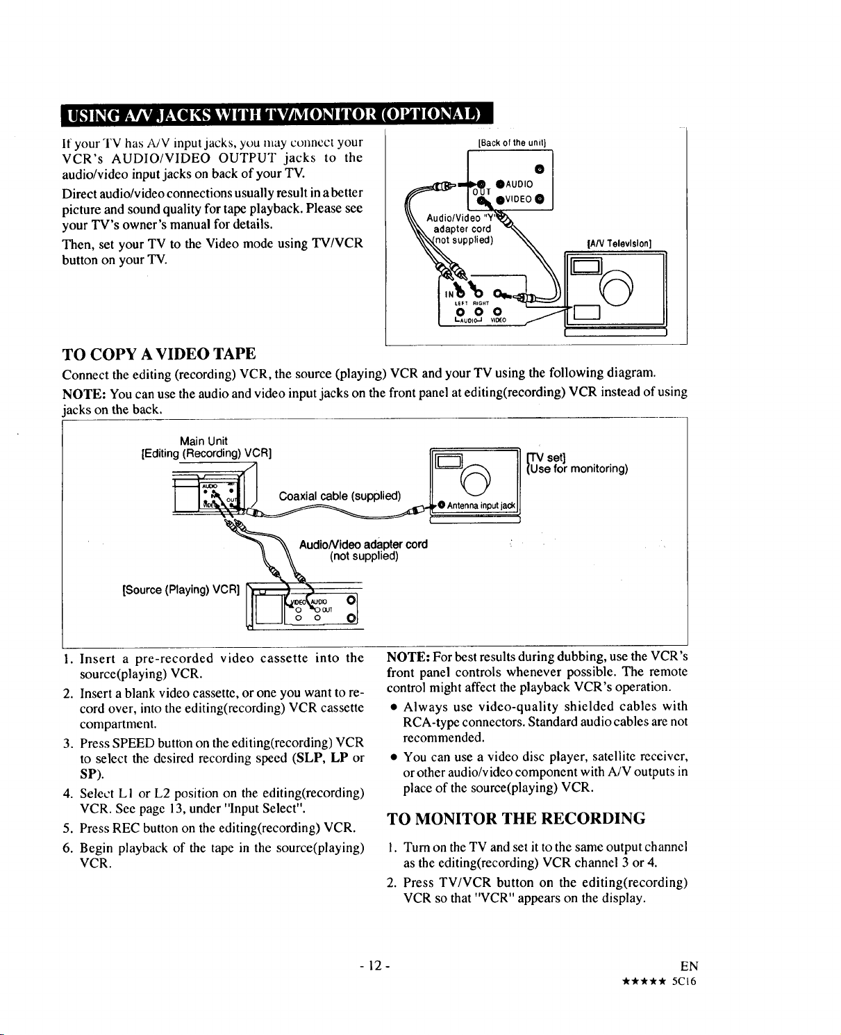
If your TV has A/V input jacks, you may connect your
VCR's AUDIO/VIDEO OUTPUT jacks to the
audio/video input jacks on back of your TV.
Direct audio/video connections usually result in a better
picture and sound quality for tape playback. Please see
your TV's owner's manual for details.
Then, set your TV to the Video mode using TV/VCR
button on your "IV.
[Back of the unit}
_lr oAUDIO0
l- ov,0 oe
ideo "Y_'_
,.v.+,,,00,
++, II°o
9oo,9
TO COPY A VIDEO TAPE
Connect the editing (recording) VCR, the source (playing) VCR and your TV using the following diagram.
NOTE: You can use the audioand video input jacks on the front panel at editing(recording) VCR instead of using
acks on the back.
Main Unit
[Editing(Recording)VCR]
* Coaxial cable (supplied)
+o
,0 Antenna input jack
U_sset]
e for monitoring)
AudioNideoadapter
(not supplied)
[Source (Playing) VCR] r_ _ _ oEo?_o_O
31
1. Insert a pre-recorded video cassette into the
source(playing) VCR.
2. Insert a blank video cassette, or one you want to re-
cord over, into the editing(recording) VCR cassette
compartment.
3. Press SPEED button on theediting(recording) VCR
to select the desired recording speed (SLP, LP or
SP).
4. Select L I or L2 position on the editing(recording)
VCR. See page 13, under "Input Select".
5. Press REC button on the editing(recording) VCR.
6. Begin playback of the tape in the source(playing)
VCR.
cord
NOTE: For best results during dubbing, use the VCR's
front panel controls whenever possible. The remote
control might affect the playback VCR's operation.
• Always use video-quality shielded cables with
RCA-type connectors. Standard audio cables are not
recommended.
• You can use a video disc player, satellite receiver,
or other audio/video component with A/V outputs in
place of the source(playing) VCR.
TO MONITOR THE RECORDING
!. Turn on the TV and set it to the same output channel
as the editing(recording) VCR channel 3 or 4.
2. Press TV/VCR button on the editing(recording)
VCR so that "VCR" appears on the display.
-12- EN
_*,_-k _r 5C16
Page 13

If your cable service supplies you with a cable converter box, you can use the basic connection shown below.
TO RECORD AND VIEW A SCRAMBLED/UNSCRAMBLED CHANNEL.
I. Press TV/VCR button so that "VCR" appears on the
display.
2. Set the TV channel to the same video output channel
as the switch located on the back of the VCR (CH3
or 4).
CableTV To VCR's ANT,IN Terminal
ConvenerBox I
3. Set the VCR channel selector to the output channel
of the Cable Converter box. (EXAMPLE CH3)
:::i-i'.illl
4. Select the channel to be recorded at the Cable Con-
verter Box.
NOTES:
• With this connection, you CANNOT record one
program while viewing another.
• Channel memory programming is NOT needed when
using this connection.
/ / _ Jack
CATV(Cable) ToVCR'sANT.OUTTerminal
Input
CONTROLLING VCR INPUT & OUTPUT
When the VCR isin the Playback mtxie, or when the TV/VCR button is in the VCR position,
your TV will receive the signals from the VCR on either channel 3 or 4. Set the 3CH/4CH
selector switchto the stationthat is not used fornormal broadcasts in your area; then set your CH3 CH4
TV to that same channel when viewing from the VCR.
The video output channel of this unit is set to channel 3 prior to shipment from the factory.
To use the external input jacks, select the "LI" or "L2" position.
• If you use the audio and video input jacks on the back of the unit, press 0, 0, I with number buttons to select
the "LI" position.
• If you use the audio and video input jacks on the front of the unit, press 0, 0, 2 with number buttons to select
the '%2" position.
You can select "LI", '%2" as a channel by using the CHANNEL "A" or "V" button.
Note: "I.,1" and "I.,2" are found before the lowest memorized channel. (Example: CH2)
[vdI I) _Ol_V_[0] |] N_ N mKN H[0]_1 [0]_1MIk"i
TV power must be on. Please see your TV's owner's manual/or details.
your
To Set TV to the Video Mode
Connection Using AV Cord Set your TV to the Video mode using TV/VCR buttonof your 'IV.
(Refer to page 12.) To set your TV to the TV mode, press TV/VCR button of your TV again.
Connection Without AV Cord Set the TV channel to the same video output channel located on the back of theVCR.
(Refer to page 10, Ii, 13.) (CH 3 or 4) Then, set your VCR to the VCR mode using TV/VCR button of your VCR.
- 13- EN
***** 5C16
Page 14

CHANNEL MEMORY PROGRAMMING
(Without a Cable Box)
Channel memory programming is NOT needed when connected to a CABLE BOX. You can program the tuner to
scan only the channels you receive in your area.
• You must use remote control for this procedure.
NOTES:
• Follow the steps below, once. Repeat it only if there is a power failure or the VCR is unplugged for more
than 3 seconds. In these cases, since the programmed channels are erased, the VCR will prompt you with
"--:--" when you turn it on.
• You must follow the steps below before attempting to play or record a video tape. If you want to play or
record a video tape BEFORE programming the tuner, you must first press POWER button to turn off the
VCR. Then, press POWER button again to turn itback on. To program the tuneragain, see "To preset channel
memory again" on this page.
After scanning, the tuner stops on the lowest memo-
rized channel.
Plug the VCR power cord
into a standard AC outlet.
The "- - : - -" flashes.
t i "
Turn on the TV and set the TV channel to the same
video output channel located on the back of the VCR.
(CH 3 or 4)
crl
Press the POWER button to
turn on the VCR so that the
"n" appears on the display.
Press the TV/VCR button so that "VCR" appears on the
display. 'q__,ANGUAGESELECT" appears on the TV
screen.
vrl
Select I(ENGLISH) or LA'_U,GESELEC'
2(ESPAIQOL -- SPANISH) ,E_,SH tO_]
with number buttons.
Press SELECT or MENU
button on the remote control tUNERSETUP
SOthat "TUNER SET UP"
appears on the TV screen.
Press SELECT button once. The tuner scans and memo-
rizes all the active channels in your area.
- ?
2 ESPA_OL
The VCR distinguishes between standard TV channels
and Cable channels. If you subscribe to cable TV,
"CATV" appears on the display. (TV mode: from CH2/
CATV mode: from CH 1)
II c.
8 P I
The TV screen retums to TV mode.
• If you want to recall the selected channels, you can
select the desired channel directly by number but-
tons on the remote control.
• The TV screen returns to TV mode when you press
MENU button in Tuner Set Up mode.
VCR
• 2
I
I
CH 02
To preset channel memory again
I
Turn on the VCR.
2
Turn on the TV and set the TV channel to the same
video output channel located on the back of the
VCR. (CH 3 or 4)
3
Press the TV/VCR button so that "VCR" appears on
the display.
4
Press MENU button. Select item 3(INITIALIZE)
with number buttons.
5
Select item I(CHAN-
NEL SET UP) with num-
ber buttons. And select
I(TV) or 2(CATV) with
number buttons.
6
Press SELECT button once. After scanning, the
tuner stops on the lowest memorized channel.
l i CHANNEL SETUP
oKrv
ADD/DELETE 08
tONI
- 14- EN
***** 5B24
Page 15

II I[O] I] D!II DIII D!_q I] !] H',t Dk_lDIII[OI; Ir.,1_,1¢,1DIm
Use this proccdurc to delete from memory the chalmcls yt)tl .t) longcr lccclvc or seldom watch and to manually
add to memory previously deleted channels.
• Turn on the TV and set the TV channel to the same video output channel located on the back of the VCR.
(CH 3 or 4)
• Press the TV/VCR button so that "VCR" appears on the display.
DELETING PRESET CHANNELS ADDING PRESET CHANNELS
TIMER PROGRAMMING
VCR SET UP
Press MENU button on the
remote control. Select item
_ITIAL_E
I i MENU
3(INITIALIZE) with num-
ber buttons.
INITIALIZE
CHANNELSET UP
SETTINGCLOCK
S LANGUAGESELECT
Select item I(CHANNEL
SET UP) with number but-
tons.
w ION|
CATV
3 AD_DELETE CH
Select item 3(ADD/DE-
I CHANNEL SET UP
LETE CH) with number but-
tons.
,.,,,;:_,iidi_=tErEc.
Enter the desired channel us-
,_' ili%
ing the number buttons. The
channel flashes.
You must precede single-digit channel numbers with a
zero (02, 03, 04 and so on).
%. ,_ :lJ'
Press ADD/DELETE button
so that "DELETE" flashes
on the display. The channel is deleted from the VCR.
• For next channel you wish to delete, select that chan-
nel and follow step [5].
• If you press ADD/DELETE button again, the chan-
nel is memorized again.
Press MENU button on the
remote control. Select item
3(INITIALIZE) with num-
TIMER PROGRAMMING
VGR SET UP
IMTIALtZE
I i MENU
ber buttons.
iNITIALIZE
CHANNELSET UPSETTINGCLOCK
LANGUAGESELECT
Select item I(CHANNEL
SET UP) with number but-
tons.
CHANNEL SET U P
, _,_ Io_l
3 AD_D_LETE CH
Select item 3(ADD/DE-
LETE CH) with number but-
tons.
r=rl
Enter the desired channel us-
,.m' 03 :llN)
n0'II %
ing the number buttons. The
channel flashes.
You must precede single-
digit channel numbers with f ....j+......
a zero (02, 03, 04 and so on). [ ,,,,,,,',o,=.......
=,,,,,,;'O_=tT_I
Press ADD/DELETE button
so that "ADD" flashes on the
display. The channel is added to the VCR.
• For next channel you wish toadd, select that channel
and follow step [5].
• If you press ADD/DELETE button again, the chan-
nel is deleted again.
Press MENU button. The TV screen returns to TV
mode.
• To check the channel(s) that has been deleted, press
CHANNEL A or 'v button.
Press MENU button. The TV screen returns to TV
mode.
• To check the channel(s) that has been added, press
CHANNEL _ or _ button.
-15- EN
•It_ _ _'Ir 5B24
Page 16

iE'I"IING THE CLOCK
Set the clock accurately for proper automatic timer recording. We suggest that you use a TV or radio station as
your time source.
• VCR Power must be on.
• Turn on the "IV and set the TV channel to the same video output channel located on the back of the VCR.
(CH 3 or 4)
• Press the TV/VCR button so that "VCR" appears on the display.
• You must use remote control for this procedure.
In the example below, the clock is to be set to:
DATE Wednesday Ist March, 1995
SETrlNG TIME 5:40PM
crq
Press MENU button on the
remote control. The main
menu appears on the TV
screen.
TIMER PROGRAMMING
VCR SETup
INrTIALtZE
I i MENU
Enter your desired HOUR
with number buttons.
MONTH DAy YEAR
0a I 01 WED 199E
I sETTING CLOCK ]
,.,OOR.M,_,_,,_,',,
0 _flt*tfi -. tiiiiiii -.
dl#'_ %,.
J
rx?
Enter your desired MINUTE
Select item 3(INITIALIZE)
with number buttons.
Select item 2(SETTING
CLOCK) with number but-
tons. The MONTH digits
flash.
INITIALIZE
CHANNELSET UP
SE_ING Q._K
s LANGUAGESELECT
I SETTINGCLOCK
M(_N TH DAY YEAR
with number buttons.
vrq
Select AM(I) or PM(2) with
number buttons.
MONTH DAY YEAR
03 I O_ WEO 1995
.OORM_rE_
I E'i'i'ING CLOCK i_l
o5 : o _** -'- - '
MONTH 0AY YEAR
03 / 0! WED 1995
SETTING CLOCK 1
HOUR MINUTE PM
os : 40 .,,,.,'F_d ,,::,,,,,I
%,A_i ad'
Frl
Enter your desired MONTH
with number buttons.
Enter your desired DAY with
number buttons.
Enter your desired YEAR
with number buttons.
The day of the week will
change automatically.
SETTING (_.OCK
MONTH DkY YEAR
I SETTINGCLOCK ]
HOORMINUTE *llN_/l_ J
MONTH DAY YEAR
03 1 01 WED 1995
I SETTING CLOCK
H UR MINUTE AMSPM
Press ADD/DELETE button to go back one step
from current step during steps [4] to [9].
Press MENU or SELECT
button to start the clock.
Although seconds are not
displayed, they begin count-
ing at 00 when you press them. Use this feature to syn-
chronize the clock as accurately as possible.
This unit has a built in calendar up to the year 2009.
• When unplugging the AC-cord or if there isa power
failure for more than 3 seconds, "- - : - -" flashes on
the display.
• If the display shows an abnormal reading or no read-
ing, unplug the power cord for more than 3 sec-
onds. Then plug it back in.
- 16 - EN
***** 5B24
Page 17

TO CHANGE CLOCK SETTING
If you want to change the clock,
1 Turn on the VCR.
2 Turn on the TV and set the TV channel to the same
video output channel located on the back of the
VCR. (CH 3 or 4)
3 Press the TV/VCR button so that "VCR" appears on
the display.
4 Press MENU button. Select item 3(INITIALIZE)
with number buttons.
5 Select item 2(SE'I'I'ING CLOCK) with number but-
tons.
6 Select desired digit with SELECT button.
7 Enter correct numbers with number buttons.
8 Press MENU button to return to original mode.
To check the Remain, Count, Clock and Channel num-
ber on the TV screen or display, press SELECT button.
Each time you press SELECT button, TV screen or dis-
play will change as follows:
<OFF mode>
I ....
O:1?:3q 2
<REMAIN mode>
'_F' Press once
D:3q ?
<COUNT mode>
_ir Press once
<CLOCK mode>
qlF Press once
TO CHANGE THE LANGUAGE
• VCR Power must be on.
• Turn on the TV and set the TV channel to the same video output channel located on the back of the VCR.
(CH 3 or 4)
• Press the TV/VCR button so that "VCR" appears on the display.
• You must use remote control for this procedure.
Press MENU button on the
remote control. The main
menu appears on the TV
screen.
Select item 3(INITIALIZE)
with number buttons.
TIMER PROGRAMMING
CHANNEL SET uP
SETTING CLOCK
s LANGUAGE SELECT
_NIT IAL _"E 1
Select item 3(LANGUAGE
SELECT) with number but-
tons.
Select I(ENGLISH) or
2(ESPAlqOL - SPANISH)
with number buttons.
LANGUAGESELECT
I ENGLISH [ONI
2 ESPANOL
LANGUAGESELECT
t ENGLISH IONI
2 ESPA_
Press MENU button. The TV screen returns to TV
mode.
- 17 - EN
***** 5B24
Page 18

VIEWING AND RECORDING THE SAME
PROGRAM
• VCR Power must be on.
• Turn on the TV and set the TV channel to the same video output channel located on the back of the VCR.
(CH 3 or 4)
• Press the TV/VCR button so that "VCR" appears on the display.
TO DELETE SCENES DURING
E:3
Insert a cassette tape with the erase-protection tab, if
necessary, rewind or fast forward the tape to the point
at which you want to begin
recording.
Counter mode appears at
counter 0:00:00 on the dis-
play.
Select the channel to be re-
corded by pressing the num-
ber buttons on the remote
control or the CHANNEL •
or • button.
o:oo:oo
CH 32]
RECORDING
While VCR remains inrecord
mode, press PAUSE button.
Note: If you do not press PAUSE button again within
five minutes, VCR will automatically return to Stop
mode. You may review the time remaining with ,,1,,
marks on the display. Each 'lr'mark shows one minute.
Press PAUSE or REC button |_Ec
to resume recording.
I _-_:_'"
r
Lsp
Press SPEED button on the
VCR to select the desired
tape speed (SP-LP-SLP).
Press REC button.
The red "O" indicator lights
on the display.
Press STOP button when re-
cording is completed.
I SP
I REC
sp
I STOP
EDIT SEARCH
To edit an unwanted segment from the already recorded
portion of tape while VCR remains in record mode.
While VCR remains inrecord mode, press PAUSE button.
Press and hold REWIND button until you have reached
the beginning of the unwanted segment. (If you rewind
past the beginning of the unwanted segment, press and
hold F.FWD button until you have reached it.)
Note: If you do not press PAUSE button again within
five minutes, VCR will automatically return to Stop
mode.
D[3
Press PAUSE or REC button to resume recording.
-18-
***** 5CI6
EN
Page 19

RECORDING ONE PROGRAM WHILE
VIEWING ANOTHER
You can record one program while viewing another. To start recording, follow steps [ 1] to [4] under "VIEWING
AND RECORDING THE SAME PROGRAM" on page 18.
TO MONITOR THE PROGRESS OF
YOUR RECORDING,
If you set the TV channel to
3 or 4 channel, press
TV/VCR button so that
"VCR" disappears from the
display.
• If you connect VCR to TV using AV cord, set your TV
to theTV mode using TV/VCR button of your TV.
Set the TV to the channel you want to watch (leave the
VCR tuned to the channel you want to record).
13:DI3:DI c. 3? If you set the TV channel to
o 17:l]]:1"7 3?
3 or 4 channel, press
TV/VCR button so that "VCR" appears on the display.
Turn on the TV and set the TV channel to the same
video output channel located on the back of the VCR.
(CH 3 or 4)
• If you connect VCR to TV using AV cord, set your
TV to the VCR mode using TV/VCR button of your
TV.
1
o:°"]
AUTOMATIC TIMER RECORDING
You may set the VCR to start and end a recording while you are away. You can set seven events to record on
specific days, daily or weekly within a ! year period.
• VCR Power must be on.
• Turn on the TV and set the TV channel to the same video output channel located on the back of the VCR.
(CH 3 or 4)
• Press the TV/VCR button so that "VCR" appears on the display.
• Clock must be set to the correct time and date before setting the timer.
• You must use remote control for this procedure.
In the example below, the timer is being set to record:
DATE Saturday 6th May, 1995 CHANNEL CH61
SETTING TIME from 7:30AM to 8:50AM TAPE SPEED LP
PnOGP_MNUM_G_i ":;......
Insert a cassette tape with the erase-protection tab, if
necessary, rewind or fast forward the tape to the point
at which you want to begin recording.
Press MENU button on the [ _.o
menu appears on the TV
remote control. The main [ _ ve.T'E"_.O_AM..,.GSET_p
screen.
Select item i(TIMER PRO-
GRAMMING) with number
buttons.
3 ,N,TLtL tZE
TAPE SPEEO
DATE
CHANNEL
Select your desired program
number with number but-
tons.
The program number 8 is used for setting Quick Set
Program only. You cannot select number 8 in the
procedure of Automatic Timer Recording.
Press SELECT button on the
remote control.
CHANNEL -2" _i ":
START TiME - - : ....
END TIME -- :....
Io sEEoi!t
iiii_iii!!lllii! DALLY ii][ii]i]][[[ii
.... 3 .:WEEKLy. ....
[ PROGFI_M NU_ER _;. ]
J ilii%'
-19-
EN
"k**,k _" 5CI6
Page 20

Select item I(ONCE) with
number buttons. The
CHANNEL digits flash.
Enter your desired CHAN-
NEL with number buttons.
Enter your desired HOUR
with number buttons.
In_OGnAM HUMBleR 1
"Jh.ill.,f_"
CHANNEL :,,,_,,,--=I,,,,
STARTTIME _'-e/-_ -
END TIME _ _-:"- :
TAPE SPEED --
I O_E TIME PR0_RAM _]
DATE - - ! - -
PROGRAM _MBER I
STARTT_*.,. - - I._
END TIME._" ._"- :
TAPESPEED '_
ON__IME PROGRAM t
DATE - -/- -
ONE TIME _M
I_GBAM MdM$8R ,
TAPE SPEED - - :-- /
OAT E - - / - -
J
ONE TIME PROGRAM
Enter your desired DAY
with number buttons.
The day of the week will
PROGRAM NUMBER I
_NNEL E,
$TARTT_ 07:30 AM
END T_E 08: O AM
TAPESPEED Lt_ $ ./"
DATE _S_'0 B ,.B_T I
•_ _ "%
J
change automatically.
Press MENU button. Pro-
gram 1is now completed.
To set another program, repeat steps [2] to [15]
starting on page 19.
OWE TIME PROGRAM l
Iq_a:)_qAMN_JMBER ,
CI4ANNEL Bl %11 I'
STARTTIME O7 : I.$::_t_.]:-- ""
Enter your desired MINUTE
with number buttons.
y0q
Select AM(I) or PM(2) with
number buttons.
Repeat steps [8]-[101 to set
END TIME - -: - _. 1,
TAPE SPEED -- " hi"
DATE _. i ,_
PROGRAM NL.i_E_ER I
DHAiMNEL S I
BTARTTIME h:: 6_#_30 A
END TME=,_ -_=_ --
I ONE TIME PROGRAM M"I
DATE _- / - -
PROGRAM NUMBER
CHAN_EL e 1
I NE TIME PROGRAM Md1
8TARTTIME Q,7:80 AM
END TIME _:,_EI_B0 A
the end time.
Select your desiredrecord- __'°_,T=M:8.R'
= [._}
ing speed SP(I), LP(9_), ,,%'_%!'8E_.,,,,.i..'i,i,!__:
SLP(3) or AUTO(4) with ......_!i.....
number buttons.
t=' ..............3
• AUTO(4) is available only with Program No. 1.
See "Just-InTime Recording" on page 28 for the use
of AUTO(4) setting.
..
Press POWER/TIMER REC
button. The "F-d" indicator
I_t I
5:51 ,,,
appears on the display. The
number of all programmed
events are displayed with current time.
NOTES:
• When the programs overlap, the earliest program
has priority.
• When the earliest program has finished andthe pro-
grams which should start still overlap, the recording
will startin order of the program number.
I , ::::::_:.%..;::i:::_,
, i 1%11i1
' I : I PROGRAM3
I '. •
I):OOAM 10:00AM 11 :OOAM 1_:00PM
If you programmed as per the above illustration the
timer recording would be carried out as follows:
9:00AM - 1!:00AM for PROGRAM 2
11:00AM - !2:00PM for PROGRAM 1
12:00PM - for PROGRAM 3
I , i ,
' I
I I
-i _ii_._._ i_..,_:_ _._
,
I
rim
Enter your desired MONTH
with number buttons.
I":D:sL£ii!iLz/
DATE _SJO 3':,WED I
• 'I_'I "% J
If you programmed as per the above illustration the
timer recording would be carried out as follows:
9:00AM - 11:00AM for PROGRAM 2
11:00AM - for PROGRAM !
- 20 -
EN
•A""t""t"'A""t, 5CI6
Page 21

DAILY PROGRAM
(MONDAY-SUNDAY)
To record a program at the same time on the same chan-
nel every day, follow steps [1] to [5] on page 19, then
step [6a] below.
1_O3RAM MJtaBER I
Select item 2(DAILY) with
number buttons.
IENOTIME _ _1_:._ -
TAPE SPEED - -
I_ILY PROGAAIO _]
OATE --I--
Continue with step [7] on page 20 onwards.
WEEKLY PROGRAM
CHECKING TIMER PROGRAMS
To check a program that is to be recorded using the
Automatic Timer Program when the VCR is in the
timer-record mode:
1) Turn on the TV and set the TV channel to the same
video output channel located on the back of the
VCR. (CH 3 or 4)
2) Press POWER/TIMER REC button so that the
"@" indicator disappears from the display.
3) Press the TV/VCR button so that "VCR" appears
on the display.
4) Follow instructions in steps [2] to [5] on page 19.
Information which was set for programming will
now appear.
To record a program at the same time on the same chan-
nel every week, follow steps [I] to [5]on page 19, then
step [6b] below.
Select item 3(WEEKLY) _o,,_E'...... E.,,,"_'_-._._ :
with number buttons. _TE .....
TAPE SPEED --
Continue with step [7] on page 20 onwards.
TO CORRECT OR CANCEL
A PROGRAM
• Press ADD/DELETE button to go back one step
from current step during steps [5]~[14].
• If you finished setting program, repeat steps [2] to
[4] on page 19. Then press SELECT button repeat-
edly until your desired digit flashes and reset pro-
gram.
• You may cancel the entire program by pressing
ADD/DELETE button at step [5].
TO STOP RECORDING
Press STOP button on the VCR.
• If you are recording using the Automatic Timer Pro-
gram, you may not operate the unit manually, but,
you may still stop the recording by pressing
STOP/EJECT button on the VCR.
NOTE: STOP button on the remote control will not
function in the Automatic Timer Recording mode.
AUTOMATIC TIMER RECORDING
HINTS
• If there a power failure or the VCR is unplugged for
more than 3 seconds, the clock setting and all timer
settings are lost.
• If the tape runs out before the end time, the VCR will
switch to the Stop mode immediately, eject the tape
and the VCR power will be turned off. The "[]" in-
dicator will flash.
• If atape is not inserted or the erase-protection tab is
removed, the "@" indicator flashes and automatic
timer recording cannot occur. Insert a tape that al-
lows recording.
• The TV that is connected to your VCR may be turned
ON or OFF when the VCR is in the timer-record mode.
- 21 - EN
***'if* 5CI6
Page 22

QUICK SET PROGRAM
You may set the VCR to start and end recording one program within 24 hours by simply pressing QUICK SET
PROGRAM button on the VCR. It is easy for you to set the timer for recording today's TV program.
* VCR power must be on to set Quick Set Program.
• Clock must be set to the correct time before setting the timer.
• Quick Set Program controls program number 8.
In the example below, the Quick Set Program is being set to record (current time is 6:00PM):
SETTING TIME from 9:30PM to 11:00PM
CHANNEL CH61
TAPE SPEED LP
NOTE: This function cannot be done by the remote control.
Insert a cassette tape with its safety tab in place. (If
necessary, rewind or fast forward the tape to the point
at which you want to begin
recording.) L_" _" I
The VCR display will 0:130:00 33
change to the count mode.
Press QUICK SET PRO-
GRAM button on the VCR. I.l_ . w_o,' IProgram number "8" ap- t s (. -_:OD,.- 37
pears on the display. _ ,
Set the desired start time.
edly or hold it down until - "_°'' ,_
Press START button repeat- [ i ,_ J
your desired start time is dis- L _8 (- . _:3D _€-33
played.
Set the desired end time.
Press END button repeat-
edly or hold it down until
-I1:013,,r 37
your desired end time is dis-
played.
Set the channel number.
Press CHANNEL • or •
button repeatedly or hold it
down until your desired
channel number is dis-
p_ m WEO s C1_ ___
E_o 1l:13O_- G
played.
7rq
Set the tape speed.
your desired tape speed is l
Press SPEED button until[displayed.. _° " t°"'
(AUTO-no display, SP, LP
or SLP)
• The tape speed can be changed at any step from [2]
to 15].
GRAM button to return to J'_ O:OD:DtJ
original mode.
Press POWER/TIMER REC button to set Quick Set
Program.
This turns the VCR power
off, and the "1_" indicator | ,_ _o
lights up on the display. The L 8:os..
program number "8" is dis-
played with current time.
CN
- 22 - EN
-or_,k 5CI6
Page 23

When the programs overlap, Quick Set Program
has priority. But if an another programhas been acti-
vated when the start time of the Quick Set Program
comes, the Quick Set program will be begun after fin-
ished the faster program.
I I
PROGRAM 2
oui, s., P,oQ,,__pR0a,AM8_
9:00PM 10:00PM 11:00PM
I i
12:00AM
TO CANCEL A QUICK SET
PROGRAM
• While setting a program; press STOP/EJECT but-
ton on the VCR.
• After setting a program; (power must be on)
First, press QUICK SET PROGRAM button.
Then, press STOP/EJECT button.
• While recording is in progress; press STOP
/EJECT button.
If you program as per the illustration the timer record-
ing would be carried out as follows.
9:00AM - 11:00AM for PROGRAM 1
11:00AM- 12:00PM for PROGRAM 8
(Quick Set Program)
12:00PM - for PROGRAM 2
TO CHECK THE START/END TIME
To check the start!end time and channel number, first
press POWER/TIMER REC button so that "[]" indi-
cator appears, then press QUICK SET PROGRAM
button once. Both the start and end time will appear for
3 seconds each, and return to the Timer Stand-by m_xle.
I_ WED
[]
8
S:D-I
!,
reT¢l WED
[] CH
START
8
9:30 61
HINTS
• If there is a power failure or the VCR is unplugged
for more than 3 seconds, the clock setting and all
timer settings will be lost.
• If the tape runs out before the end time, the VCR will
switch to the Stop mode immediately, eject the tape
and the VCR power will be turned off. The "1_" in-
dicator will flash.
• If a tape is not inserted or the erase-protection tab is
removed, the "[]" indicator flashes and automatic
timer recording cannot occur. Insert a tape that al-
lows recording.
• The TV that is connected to your VCR may be
turned ON or OFF when the VCR is in the timer-re-
cord mode.
I,
ra]_! WED
[] CH
8
- 23 - EN
,k-Cr,_ 4_-k 5C16
Page 24

INDEX SEARCH
This feature provides a method of indexing the starting point so that it can be easily returned to in either fast forward
or rewind mode.
• The index mark will be made automatically when the REC button is pressed. It will also be marked at the starting
point of Timer recording and OTR.
• The index mark is not recorded if the PAUSE/STILL button is pressed and released during recording.
• The time gap between making the index marks on the tape should be greater than 1 minute for SP recording, 2
minutes for LP recording and 3 minutes for SLP recording.
NOTES:
• VCR Power must be on.
• Turn on the TV and set the TV channel to the same video output channel located on the back of the VCR.
(CH 3 or 4)
• Press the TV/VCR button so that "VCR" appears on the display.
• You must use remote control for this procedure.
Example: You are watching program number 4 and want to fast forward to program number 7. You must skip
three programs.
CURRENT PLAYBACK PROGRAM
I P,o._I p,o.=I ,,o.3_ Pro.51P,o.eI Pro.71
4 3 2 1 1 2 3
INDEX MARK
II
PressINDEX SEARCH but-
ton. Index Search mode ap-
pears on the TV screen.
Press the number button cor-
responding to the number of
programs that you want to
skip.
To correct the Index num-
ber, press DELETE button
and re-enter the correct
number.
Press REWIND or F.FWD
INDIE_I_ARCH
button. The VCR begins re-
winding or fast forwarding
then goes into playback
mode at the beginning of de-
• J' u
sired program.
Note: Every time an index signal is skipped, the num-
ber in the program indicator decreases by one.
When the preset program is
reached, normal playback
will start.
Notes:
• Index search can be set upto 20.
• This function is not operative in recording mode.
• Procedures must be followed within 30 seconds,
from steps [1] to [2]. Otherwise the Index Search
mode will be cancelled.
• A video cassette must be inserted inthe VCR for this
function to work.
• Press STOP button on the VCR or remote control
unit to exit the Index Search mode.
- 24 - EN
• r_gc_r it 5B24
Page 25

TIME SEARCH
The Time Search function makes it possible to quickly advance the tape from any position by entering the exact
desired amount of playback time of the part that you want to skip.
• VCR Power must be on.
• Turn on the TV and set the TV channel to the same video output channel located on the back of the VCR.
(CH 3 or 4)
• Press the TV/VCR button so that "VCR" appears on the display.
• You must use remote control for this procedure.
Example: To watch a program after 2 hours 53 minutes from present position to forward direction.
Notes:
Press TIME SEARCH but-
ton. The HOUR digits flash.
Enter the desired hour with
number buttons.
]
• Time search can be set up to 9:59.
• Procedures must be followed within 30 seconds
from steps [1] to [3]. Otherwise the Time Search
mode will be cancelled.
• This function is not operative in recording mode.
• A video cassette must be inserted in the VCR for this
function to work.
• Press STOP button on the VCR or remote control
unit to exit the Time Search mode.
Enter the desired minutes
with number buttons.
To correct the time, press
DELETE button and re-
peat steps [1] to [3].
Press EFWD or REWIND
button. The tape will move
to the specified point.
Note: The time counts down
as the searching progresses.
When 0:00 is reached, the
tape will start playback
automatically.
- 25 - EN
_r ,lit,lit_ _ 5B24
Page 26

BLANK SEARCH
This function enables you to search lot the unrecorded porlioJ, ol the tapc in the forward direction.
• Tape must be fully rewound.
• VCR Power must be on.
• Turn on the TV and set the TV channel to the same video output channel located on the back of the VCR.
(CH 3 or 4)
• Press the TV/VCR button so that "VCR" appears on the display.
• You must use remote control for this procedure.
Note:
• A video cassette must be inserted in the VCR for this
Press BLANK SEARCH
button. Blank Search func-
tion starts automatically in
the forward direction.
function to work.
vrl
The VCR begins fast for-
warding to the beginning of
the blank part of the tape.
The tape will automatically
stop.
I STOP
- 26 -
"k"Or"_"_ _ 5B24
EN
Page 27

SETTING THE REMAINING TIME
You can set the remaining tape running time of your tape.
• If your cassette tape length is T-130 or less, select "~T 130". For example, the popular T- 120 cassette tape calls
for the "~Ti 30" selection. If your cassette tape is T-140 or greater, select "T140-". Then the tape remaining
indication will be correct.
NOTES:
• VCR Power must be on.
• Turn on the TV and set the TV channel to the same video output channel located on the back of the VCR.
(CH 3 or 4)
• Press the TV/VCR button so that "VCR" appears on the display.
• You must use remote control for this procedure.
REMAINING TAPE RUNNING TIME
FT1
Press MENU button. Select
1 11MER PROGRAMMING
item 2(VCR SET UP) with
number buttons.
Select "-TI 30" or 'q'l 40~"
with 1 button.
Press MENU button to re-
turn to normal mode.
To check the remain time, /'_'Y" 1
press SELECT button on the /
remote control unit until RE-
MAIN appears on TV
screen. ,o REM _,,N .... T,30
Notes:
VCR SET UP
3 INITIALIZE
MENU ]
TAPE SELECT ~T1
REPEAT PLAY
RENTAL
i ........ t
DISPLAY
• Since the reel diameter and tape thickness are not
common to all cassettes, the time count differs from
cassette to cassette. Use the time display as an infor-
mative number only.
• During recording, the remaining tape running time
is estimated based on the current recording mode
(SP, LP, SLP).
• During playback the remaining tape running time is
calculated based on the current playback mode.
• Remain time will not appear on TV screen while in
the Fast forward or Rewind Mode.
• There will be a delay of up to 1 minute before the
remain time appears on the TV display.
Note:
The use of the following tapes will result in difference
between the displayed remaining time and actual time
to the end of the tape:
• Tape housed in a VHS-C cassette adapter.
• Shorter tape length such as a 10-minute cassette
• T-180 cassette. In this case the display may read 2
Hours, 40 Minutes at the start point of the tape in SP
mode.
• In the Remain Time Mode calculating will start
when the cassette tape is inserted and PLAY button
is pressed.
While calculating, the TV screen shows as illus-
trated.
• A video cassette must be inserted in the VCR for this
function to work.
- 27 - EN
** €__r_ 5B24
Page 28

JUST-IN TIME RECORDING
This function allows you to fully utilize the available tape length for timer recording. The VCR calculates the
remaining tape amount and then adjusts the tape speed from SP to SLP as needed.
If it is suspected that the end of the tape will be reached before the reserved program ends (as long as SP mode is
kept all the way), set recording mode to AUTO. This function is available only with Program No. 1 and Quick Set
Program.
The auto mode starts recording in SP mode. The internal circuit compares the rest of the program against the
available tape length. If the internal circuit determines that the available tape is not long enough to record the
program in the SP mode, the Recording mode is automatically changed to SLP mode. This will assure coverage
of the desired timer program before the end of the tape is reached.
Conventional Video Recording
Recording In SP mode for 40 minutes
Just-In Time Recording
Recording In SP mode
for 30 minutes
_.. Recording modeautomatically
changes to SLP mode
Notes:
• Set the tape remainder switch ("~TI30" or "I'140J') to the tape loaded.
• Even if SLP mode is selected, just-in time recording cannot compensate for a tape length which may be too
short.
• A momentary picture break up will occur at the point on the tape when the recording speed changes from SP
to SLP.
• The displayed remaining tape running time may not always match the actual remaining time on the tape (usually
longer than the actual time). It is recommended to set the end of the reserved recording time several minutes
after the end of the TV program.
Tape End
20minutesof theprogramis
left unrecorded
Recording in SLP mode
for30minutes
I
- 28 - EN
_.¢r_ 5B24
Page 29

OTR (ONE TOUCH RECORDING)
The One Touch Recording function enables you to record a program simply by pressing OTR button on the VCR.
According to the table, simply press OTR button as many times as needed to set the desired recording length. The
channel number to be recorded and recording length will be shown on the display.
NOTE: This function cannot be done by the remote control.
DISPLAY
0:00
0:30
i:00
!:30
2:00
2:30
3:00
3:30
4:00
4:30
5:00
5:30
6:00
6:30
7:00
7:30
8:00
0:00
LENGTH
0:00
30 minutes
60 minutes
90 minutes
120 minutes
150 minutes
180 minutes
210 minutes
240 minutes
270 minutes
300 minutes
330 minutes
360 minutes
390 minutes
420 minutes
450 minutes
480 minutes
0:00
Turn on the VCR.
Set the VCR to the channel to be recorded.
Press OTR button.
i OTR (_:20)
SP
Recording starts immediately when the OTR button is
pressed, at least two times whether if you are watching
the same or a different channel. T!)e recording length
will be determined by the number of times you press
OTR button.
PUSH(ES)
1push
2 pushes
3 pushes
4 pushes
5 pushes
6 pushes
7 pushes
8 pushes
9 pushes
10 pushes
II pushes
12 pushes
13 pushes
14 pushes
15 pushes
16 pushes
17 pushes
18 pushes
• Each time you press OTR button, you will extend the recording time by 30 minutes ata time up to 8-hours (or
to the end of the tape).
• When OTR button is pressed 18 times, the VCR will switch to the Stop mode immediately and the VCR power
will be turned off.
• To stop the OTR operation, press STOP button.
• The recording length time remaining is indicated on the display as the recording is started.
• Recording stops when 0:00 is reached.
• Please note that in the SLP mode maximum recording time, assuming the tape is started at the beginning, is 8
hours using T-160 (or 6 hours using T- 120).
• The TV that is connected to your VCR may be turned on or off during OTR recording.
MONITORING RECORDING
If you set the TV channel to 3 oi 4 channel, press
TV/VCR button so that "VCR" appears on the display.
Turn on the TV and set the TV channcl to the same
video output channel located on the back of the VCR.
(CH 3 or 4)
• If you connect VCR to TV using AV cord, set your TV
- 29- EN
to the VCR mode using TV/VCR button of your TV.
-A-,A-,k_ _ 5CI6
Page 30

PLAYBACK
Turn on the TV and set the TV channel to the same
video output channel located on the back of the VCR.
(CH3 or 4)
If atape is already in the VCR, press PLAY button on
the VCR. Power will turn on and playback will start
automatically. (Direct Button Operation)
vrl
Insert a tape. VCR will automatically turn on. Press
PLAY button.
(If the erase-protection tab has been removed, the
VCR will start playback automatically.)
AUTO REPEAT PLAYBACK
The VCR has an auto repeat function that allows you to repeat a tape indefinitely.
• VCR Power must be on.
• Turn on the TV and set the TV channel to the same video output channel located on the back of the VCR.
(CH 3 or 4)
• Press the TV/VCR button so that "VCR" appears on the display.
• You must use remote control for this procedure.
Ifa tape is already in the VCR, Press POWER button
to turn on, and then press PLAY button on the re-
mote control.
Press STOP button when playback is completed.
TO EXIT THE REPEAT PLAY MODE
Press MENU button on the
remote control. Select item
2(VCR SET UP) with num-
ber buttons.
TIMER pROGRAM M4NO
VGR SETUP
NTIALIZE
I i MENU
Select item 2(REPEAT
PLAY) with number but-
tons.
"ON" will appear next to
TAPESELECT -T130
REPEAT PLAY
RENTAL
Ii VCRSETUP ]
'_REPEAT PLAY".
Repeat playback will start
automatically.
_ IREPEAT PLAY i_.
Note: Once you select the repeat play mode, it stays in
effect even after you turn off the VCR.
Repeat steps [1] and [2]. "ON" will then disappear from
the menu.
- 30-
EN
"A"k _r _ 5C16
Page 31

REN'IAL PLAY
This function enables you to improve tile picture quality when playing back worn cassettes such as those rented
from a video shop.
• VCR Power must be on.
• Turn on the TV and set the TV channel to the same video output channel located on the back of the VCR.
(CH 3 or 4)
• Press the TV/VCR button so that "VCR" appears on the display.
• You must use remote control for this procedure.
TO EXIT THE RENTAL PLAY MODE
Insert rental tape into VCR. VCR will automatically
start tape playback.
Press MENU button on the ,E_
remote control. Select item _ vc,sE,uP_,T_
2(VCR SET UP) with num-
ber buttons.
Select item 3(RENTAL) T,,_L_Eo_°" -_,3
with number buttons. _"_
Press SELECT button re- I
peatedly to select "ON".
NOTES:
• Once you select the rental play mode, it stays in ef-
fect even after you turn off the VCR.
• Selecting ON or OFF must be done in the play mode
only.
1 TIMER pF_GP_MMtNG
L
RENTAt ON
Repeat steps [I] to [3]. Then, follow step [4], but select
"OFF" for normal playback.
- 31 - EN
-,4_ 5CI6
Page 32

COUNTER MEMORY
The TAPE COUNTER MEMORY button can be used
during rewind or fast forward to automatically stop the
tape when the counter reaches a preset memory position
of approx.0:00:00.
For example, this feature can be used to return the tape
to a pre-selected position immediately after recording,
or to repeatedly playback a certain portion of a tape.
NOTE: You must use remote control forthis procedure.
7rl
Insert a cassette tape with its safety tabin place, if nec-
essary, rewind or fast forward the tape to the point at
which you want to begin recording.
rT1
If the counter is not shown
0:00:00, press TAPE
COUNTER RESET button
to reset to 0:00:00.
Tape Start Fast Forwards Auto-Stop Rewinds Tape End
Counter Point
TO CANCEL THE COUNTER MEMORY
When the counter appears
on the display, press TAPE
COUNTER MEMORY bu t-
ton so that "M" disappears
from the TV screen.
Press TAPE COUNTER
MEMORY button so that
"M" appears on the TV
screen.
Press RECORD or PLAY button.
Press STOP button when re-
cording or playback is com-
pleted .........
(If the counter is not displayed, press SELECT button
so that the counter appears on the VCR display or on
the TV screen.)
To activate the counter (.m.,.,
memory function, press RE-
WIND button. The tape will
automatically stop when the
counter retums to 0:00:00. . o:,_:_o
ISTO P
- 32 - E_
_r,k _ _t_r 5C
Page 33

SPECIAL FEATURES
l Picture Search (SP/LP/SLP Mode) J
You may view a video tape at a high speed in either a
forward or reverse direction. This feature is useful in
finding or skipping over a particular scene on a tape. In
this mode, the sound will be muted.
Forward Direction:
When in the Play mode, press F.FWD button to view
the tape at a fast speed in the forward direction.
Reverse Direction:
To view the tape at a fast speed in the reverse direc-
tion, press REWIND button in the Play mode.
For normal speed, simply press PLAY button.
Super High Speed Search (LP/SLP Mode) J
For Picture Search in super high speed:
1) Press either F.FWD or REWIND button while the
unit is in the Play mode.
2) Release button.
3) Depress it again. The unit will now search in super
high speed.
For normal playback simply press PLAY button.
Tracking Adjustment -"DTR"
• Tracking adjustment will be set automatically (Digi-
tal TRacking function) when you start playback.
"DTR" appears on the display.
• When playing pre-recorded tapes or tapes recorded
on units other than your own, noise lines (black and
white streaks) may appear on the playback picture.
If this occurs, adjust the tracking control by pressing
CH • or • button until the streaks disappear. To
return to the DTR function, stop the tape once and
start playback again.
Slow Tracking
• You can reduce the noise lines by pressing CH • or
]
• button in slow mode, too. Slow tracking adjust-
ment will not be set automatically.
Note: Press SLOW button in Still mode and press
CH • or • button until the streaks disappear. To
return to Still mode, press PAUSE/STILL button
again.
This enables you to see the picture in its entirety
without distracting noise lines.
Auto Rewind
Still Picture During Playback
If you press PAUSE button during playback, the picture
will "freeze" on the screen. You may use this feature to
study details of a particular scene. Press PLAY button
to continue playback.
NOTE: The VCR will automatically switch to the Stop
mode, if it is left in the Pause mode for more than five
minutes.
Vertical Hold Control [
When the picture begins to vibrate vertically, adjust to
stabilize the picture by pressing CH &or • button on
the VCR.
NOTES:
• This adjustment works only in the Still mode with
CH • or • button on the VCR.
• When the picture is distorted or roiling vertically,
adjust vertical hold control on your TV.
• Some newer TV's do not have a user adjustable ver-
tical hold control.
When the end of a tape is reached during recording,
playback, or fast-forward, the tape will automatically
rewind to the beginning (or to the 0:00:00 counter read-
ing if the memory function is activated), eject, and the
VCR will turn off.
NOTES:
• The tape will not auto-rewind during timer recording
or One Touch Recording.
• When the tape is rewound to the preset memory po-
sition, the tape will not eject and the VCR will not
turn off.
I Slow Motion I
Press SLOW button to reduce the playback speed. The
VCR mutes the sound during slow motion. You can
control the speed by pressing EFWD button (faster) or
REWIND button (slower).
PressPLAY buttontoreturnto normalplayback.
- 33 -
EN
_*,k* t 5CI6
Page 34

VIDEO CASSETTE TAPE
This VCR will operate with any cassette that has the
VHS mark. For best results we recommend the use of
high-quality tapes.
• Do not use poor quality or damaged tapes.
The table below shows the recording/playback time us-
ing "1"-60,T-120 or T-160 tapes in the SP, LP or SLP
mode.
MODE
T-60 T-160
SP Mode I hour 2-2/3 hours
LP Mode 2 hours 5-I/3 hours
SLPMode 3 hours 8 hours
CASSE'ITE
3"-i20
2 hours
4 hours
6 hours
When handling video tapes, follow the precautions be-
low:
• Avoid moisture, which can condense on the tape if
it ismoved from a cold place to a warm place. Play-
ing a tape that has moisture in it will damage the tape
and your VCR. Before using a tape with these con-
ditions, wait until the tape has wanned to room tem-
perature and the moisture has evaporated.
• Avoid extreme heat, high humidity and magnetic
fields.
• Do not tamper with the Cassette mechanism.
• Do not touch the tape with your fingers.
INSERTING A CASSETTE
Insert the cassette in the direction as shown. Push in
gently, but continuously, on the center-back of the cas-
sette until it is drawn into the VCR.
The VCR will automatically turn on, and cassette-in
indicator will light when the cassette is properly in-
serted.
CORRECT f _.
II n _t j
WRONG
REMOVING A CASSETTE
Press EJECT button on the unit or on the remote con-
trol.
When the cassette-in indicator goes off and the cassette
stops moving, pull the cassette out of the cassette com-
partment and store it properly.
ERASE PREVENTION
You may prevent accidental erasing of a tape by break-
ing off the tab on the back edge of the cassette. If you
decide to record on the tape again, cover the hole with
plastic tape.
NTab
Plastic Tape
Store the cassette in its case as shown.
- 34-
EN
***** 5CI6
Page 35

TROUBLESHOOTING GUIDE
If you have followed the instructions contained in this manual and have difficulty in operating your VCR, locate
the SYMPTOM in the left column below. Check the corresponding POSSIBLE CAUSE and CORRECTIVE
ACTION columns to remedy the problem.
SYMPTOM CORRECTIVE ACTION
No power. • • Connect power cord to AC outlet.
• • Press POWER button to turn on the VCR.
Timer recording is not • • Set the timer recording correctly.
possible. • • Set VCR clock correctly.
Rec mode cannot be
• • Place vinyl tape over missing safety tab.
engaged.
No picture or poor picture
on playback.
• The TV fine tuning is not set correctly. • Fine tune your TV.
No picture on TV. • The VCR is in TV mode. • Press TV/VCR button.
Noise in picture on * Video heads are dirty. • Head cleaning is necessary, consult the
playback, nearest Sears Authorized Service Center.
Playback picture is • The TRACKING control is not set • Adjust TRACKING control for a better
partially noisy, correctly, picture.
On-the-air TV programs • Connections are not correctly made. • Re-check the ANT. IN and ANT. OUT
cannot be seen. connections.
No operation by infrared • Weak batteries. • Check the batteries in Infrared Remote
Remote Control. Control.
Operation buttons do not • Channel Memory Programming is • See "Note" under "Channel Memory
work after there is a proceeded because programmed Programming" on page 14.
power failure or you move channels are erased.
your VCR.
POSSIBLE CAUSE
Power cord is not connected.
VCR POWER is off.
The timer recording is set incorrectly.
VCR clock is not set correctly.
The record safety tab on cassette is
missing.
The TV channel selector is not set to
the proper channel.
On playback, set the TV to channel 3 or 4
for video output channel. Then, press
TV/VCR button so that "VCR" appears on
the display.
- 35 -
Page 36

MAINTENANCE
[l_! LIK_I_JII[_[lfl
• Wipe the front panel and other exterior surfaces of
the VCR with a soft cloth immersed in lukewarm
water and wrung dry.
• Never use a solvent oralcohol. Do not spray insecticide
liquidnear the VCR. Such chemicals may cause dam-
age and discoloration to the exposed surfaces.
• Should your VCR become inoperative, do not try to
correct the problem by yourself. There are no user-
serviceable parts inside. Turn off, unplug the power
cord, and take the unit to Sears Authorized Service
Center for servicing.
Picture playback may become blurred or interrupted
while the TV program reception is clear. This does
not mean that the recorded program has been erased.
Dirt accumulated on the video heads after long pe-
riods of use, or the usage of rental or worn tapes can
cause this problem. If a steaky or snowy picture ap-
pears during playback, the heads in your VCR may
need to be cleaned. Please visit your local
Audio/Video store and purchase a good quality VHS
Video Head Cleaner. Remember to read the instruc-
tions included with the head cleaner before use.
Clean heads only when problems occur. If this does
not correct the problem, consult the nearest Sears
Authorized Service Center. Professional video head
cleaning requires highly technical attention.
SEARS SERVICE
Your Sears Video Cassette Recorder has added value
when you consider that Sears has service units nation-
wide staffed with Sears trained tecbnicians,.,profes-
ional techniciansspecifically trainedon Sears home
tertainment products, having the parts, tools and
quipment to insure that we meet our led e to ...
We Service What We Sell". P g you
HOW TO ORDER REPAIR PARTS
Now that you have purchased your Video Cassette Re-
corder, should a need ever exist for repair parts to serv-
ice, simpl), contact an)' Sears Service Centeror Sears,
..... ,e. fr _f#O#g¢
Roebuck and Co store. Be sure toprovide allpertinent
facts when you call or visit.
The Model Number will be found on the rear of cabi-
net. Always mention the Model Number when re-
questing service or repair parts for your VCR.
- 36 -
/
EN
_'_"k _-k 5B24
Page 37

SPECIFICATIONS
Television system
Video head
Tape width
Tape speed
SP
LP
SLP
Tuner channel
VHF
UHF
Cable channel
RF converter
Converter output
Timer indication
Operating temperature
Terminals
Antenna input
Antenna output
Video input/output
Audio input/output
: NTSC, TV standard
: Rotary 4-head Double
Azimuth Video System
: l/2inch (12.65mm)
: 33.35mm/sec.
: 16.67mm/sec.
: 11.12mm/sec.
: #2~#13
: # 14~#69
5A, A-5 - A-l, A ~ W+84
Built-in VHF converter
VHF Channel 3 or 4.
: AM/PM 12-hour system
: 5°C~40°C (41°F~I04°F)
: F type connector x 1
: F type connector x 1
: RCA connector x 3
: RCA connector x 3
Video output level
Video output impedance
Audio output level
Video input level
Audio input level
: 1Vp-p
: 75_
: -6dBv (IKHz)
: 0.5-2.0Vp-p
: -10dBv
Video S/N ratio
SP
: More than 42dB
Audio S/N ratio
SP
: More than 38dB
C01I11101ItK_I_II [,0_IIKO_3
Power requirement
Power consumption
Dimensions
: 120V, 60Hz
: 17 Watts
: W 14-1/4" (360ram)
H 3-5/8" (92mm)
D 10" (252mm)
Weight
Accessories, included
: 7.01bs. (3.2 Kg.) (Approx.)
: Remote control unit
2 "AA" Batteries
: Owner's Manual
: Coaxial cable
• Designs and specifications are subject to change
without notice and without our legal obligation.
37 - EN
•_* "A"** 5B24
Page 38

MEMO
- 38 -
EN
_ _ ,A,,k-k 5B24
Page 39

Forthe repair or replacement parts youneed
Call7 am - 7 pm, 7 days aweek
1-800-366-PART
(1-800-366-7278)
For in-homemajor brand repair service
Call24 hours a day,7 daysa week
1-800-4-REPAIR
(1-800-473-7247)
Forthe location of a
SearsRepair Service Center in yourarea
Call24 hours a day, 7 days a week
1-800-488-1222
mmmmmm
mmmmmm
For informationon purchasinga Sears
Maintenance Agreementor to inquire
about an existing Agreement
call 9 am - 5 pm, Monday-Saturday
1-800-827-6655
America's Repair Specialists
Page 40

OWNER'S
SEARS
VIDEO CASSETTE
RECORDER WITH
REMOTE CONTROL
Your Sears Video Cassette Recorder has added value when
you consider that Sears has service units nationwide staffed
with Sears trained technicians-professional technicians spe-
cifically trained on Sears home entertainment products, hav-
ing the parts, tools and equipment to ensure that we meet
our pledge to you - "We Service What We Sell."
Should a need ever exist for repair parts or service, simply
contact any Sears Service Center/Department.
MANUAL
MODEL NO.
934.55125590
Z
IWARRANTYJ
For 90 days from the date of purchase, Sears will repair any
defect in material or workmanship in this video cassette re-
corder, free of charge, For one year from the date of pur-
chase, Sears will supply, at no charge, replacement for
defective parts.
The above warranty coverage applies only to video cassette
recorders which are used for private household purposes.
TO OBTAIN WARRANTY SERVICE, SIMPLY RETURN
THE VIDEO CASSETTE RECORDER TO THE NEAREST
SEARS SERVICE CENTER / DEPARTMENT IN THE
UNITED STATES.
This warranty gives you specific legal rights, and you may
also have other rights which vary from state to state.
Sears, Roebuck and Co.
Dept. 817WA, Hoffman Estates, IL 60179
Printed in Hong Kong
0VMN01588
H3380UD *_'***
 Loading...