

Sears 934.53735190 series Owner's Manual
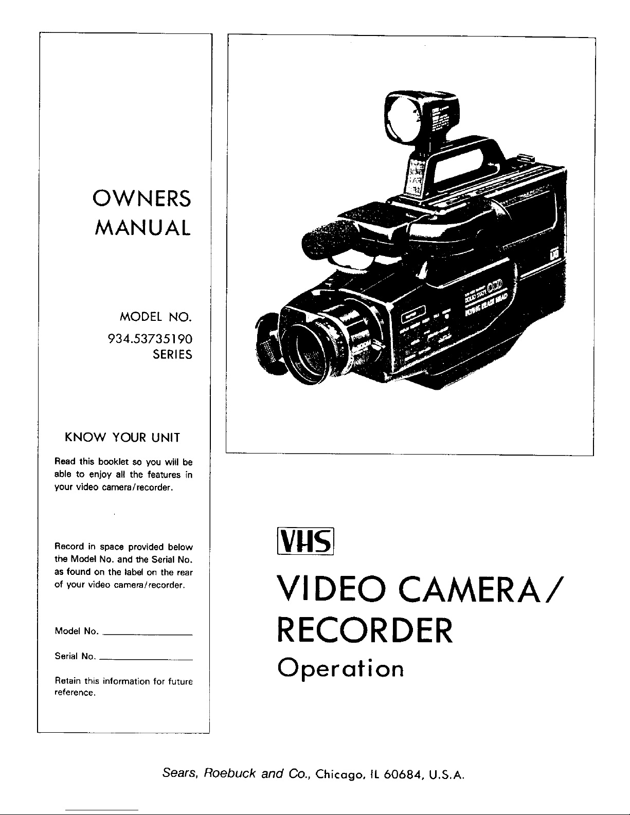
OWNERS
MANUAL
MODEL NO.
934.53735190
SERIES
KNOW YOUR UNIT
Read this booklet so you will be
able to enjoy alt the features in
your video camera/recorder.
Record in space provided below
the Model No. and the Serial No.
as found on the label on the rear
of your video camera/recorder,
Model No,
Serial No.
Retain this information for future
reference,
[vHs]
VI DEO CAMERA/
RECORDER
Operation
Sears, Roebuck and Co., Chicago, IL 60684, U.S.A.
WARNING: TO PREVENT FIRE OR SHOCK HAZARD, DO NOT
EXPOSE THIS UNIT TO RAIN OR MOISTURE.
RISK OF ELECTRIC SHOCK
DO NOT OPEN
CAUTION: TO REDUCE THE RISK OF ELECTRIC SHOCK,
DO NOT REMOVE COVER (OR BACK).
NO USER -- SERVICEABLE PARTS INSIDE.
REFER SERVICING TO QUALIFIED SERVICE
PERSONNEL.
This symbol warns the user that uninsulated voltage wi_in
the unit may have sufficient magnitude re cause electric
shock. Therefore, it is dangerous to make any kind of con-
tact with any inside part of this unit.
This symbol alerts the user that important literature con-
cerning the operation and maintenance of this unit has been
included. Therefore, it should be read carefully in order to
avoid any problems.
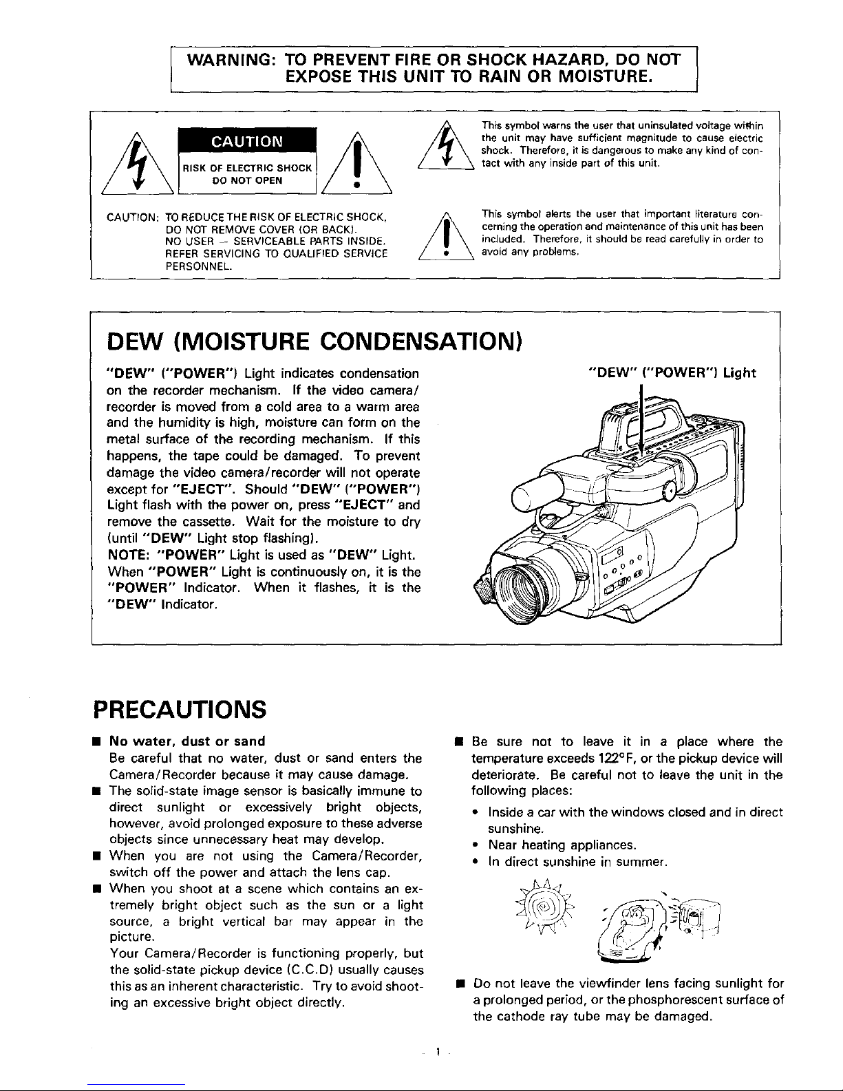
DEW (MOISTURE CONDENSATION)
"DEW" ("POWER") Light indicates condensation
on the recorder mechanism. If the video camera/
recorder is moved from a cold area to a warm area
and the humidity is high, moisture can form on the
metal surface of the recording mechanism. If this
happens, the tape could be damaged. To prevent
damage the video camera/recorder will not operate
except for "EJECT". Should "DEW" ("POWER")
Light flash with the power on, press "EJECT" and
remove the cassette. Wait for the moisture to dry
(until "DEW" Light stop flashing).
NOTE: "POWER" Light is used as "DEW" Light.
When "POWER" Light is continuously on, it is the
"POWER" Indicator. When it flashes, it is the
"DEW" Indicator.
"DEW"
"POWER") Light
PRECAUTIONS
• No water, dust or sand
Be careful that no water, dust or sand enters the
Camera/Recorder because it may cause damage.
• The solid-state image sensor is basically immune to
direct sunlight or excessively bright objects,
however, avoid prolonged exposure to these adverse
objects since unnecessary heat may develop.
• When you are not using the Camera/Recorder,
switch off the power and attach the lens cap.
• When you shoot at a scene which contains an ex-
tremely bright object such as the sun or a light
source, a bright vertical bar may appear in the
picture.
Your Camera/Recorder is functioning properly, but
the solid-state pickup device (C.C.D) usually causes
this as an inherent characteristic. Try to avoid shoot-
ing an excessive bright object directly.
• Be sure not to leave it an a place where the
temperature exceeds 122°F, or the pickup device will
deteriorate. Be careful not to leave the unit in the
following places:
• Inside a car with the windows closed and in direct
sunshine.
• Near heating appliances.
• In direct sunshine in summer.
• Do not leave the viewfinder lens facing sunlight for
a prolonged period, or the phosphorescent surface of
the cathode ray tube may be damaged.
1
Congratulations on buying the _ Video Camera/Recorder. For maximum pleasure and convenience
please read these simple instructions before operating your Camera/Recorder.
NOTES: • This Video Camera/Recorder is compatible with any video cassette bearing the _] mark.
• _ is designed to expand your opportunities for in-home TV viewing and not for any usage
which might violate the copyright laws.
• _.__1_'_ The Video Camera/Recorder with this marking incorporates _ high-quality
picture technology and is compatible with any Video Cassette Recorders bearing the
[_ mark.
FEATU RES
• CCD solid-state camera pickup
• HO_ High Quality picture technology
• Auto Focus Power Zoom Lens with macro feature
• Electronic Viewfinder
• Full record and playback capability with standard
cassette
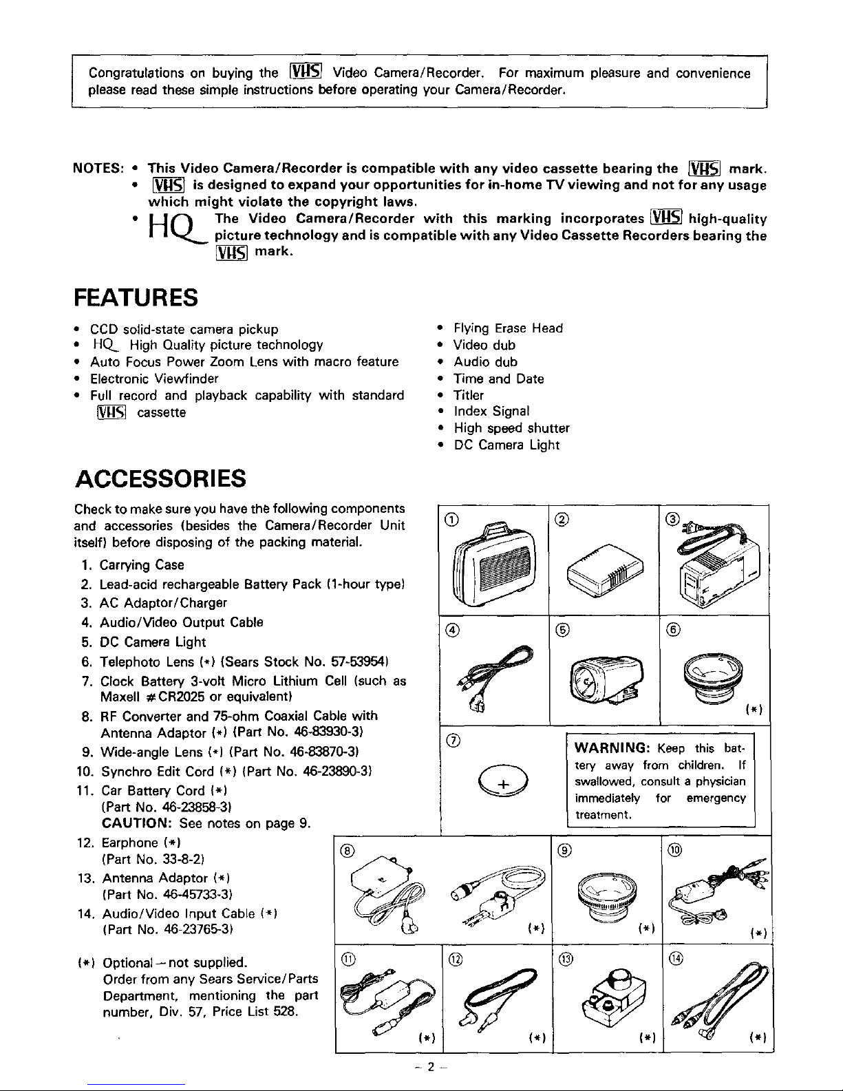
ACCESSORIES
Check to make sure you have the following components
and accessories (besides the Camera/Recorder Unit
itself) before disposing of the packing material.
1, Carrying Case
2. Lead-acid rechargeable Battery Pack (1-hour type)
3. AC Adaptor/Charger
4. Audio/Video Output Cable
5. DC Camera Light
6. Telephoto Lens (*) (Sears Stock No. 57-53954)
7. Clock Battery 3-volt Micro Lithium Cell (such as
MaxeU #CR2025 or equivalent)
8. RF Converter and 75-ohm Coaxial Cable with
Antenna Adaptor (*) (Part No. 46-83930-3)
9. Wide-angle Lens (*) (Part No. 46-83870-3)
10. Synchro Edit Cord (*) (Part No, 46-23890-3)
11. Car Battery Cord (*)
(Part No. 46-23858-3)
CAUTION: See notes on page 9.
12. Earphone (*)
(Part No. 33-8-2)
13, Antenna Adaptor (*)
(Part No. 46-45733-3)
14. Audio/video Input Cable (*)
(Part No, 46-23765-3)
(*) Optional-- not supplied.
Order from any Sears Service/Parts
Department, mentioning the part
number, Div. 57, Price List 528.
®
• Flying Erase Head
• Video dub
• Audio dub
• Time and Date
• Titler
• Index Signal
• High speed shutter
• DC Camera Light
®
@
® ®
_(*)
®
WARNING: Keep this bat-
tery away from children, If
swallowed, consult a physician
immediately for emergency
treatment.
®
_(*)
@
@
(*)
-2-
IMPORTANT SAFEGUARDS
In addition to the careful attention devoted to quality standards in the manufacture of your video product, safety ts a major factor in the
design of every instrument. But, safety is your responsibility too.
This page lists important information that will help to assure your enjoyment and proper use of a Video Camera/Recorder and accessory
equipment. Please read it carefully before operating your video product and keep it in a handy place for future reference
INSTALLATION
1 Read and Follow Instructions--All the safety and operat-
ing instructions should be read before the video product
is operated. Follow all operating and use instructions
7 Power-Cord Protection--Power-supply cords should be
routed so that they are not likely to be walked on or pinched
by items placed upon or against them, paying particular attention
to cords at plugs, conven,ence receptacles, and the point where
they exit from the appliance.
8 Ventilation--Slots and openings m the cabinet are pro-
vided for ventilation to ensure reliable operation of the video
product and to protect it from overheating. These openings must
not be blocked or covered The openings should never be blocked
by placing the video product on a bed, sofa, rug, or other similar
surface. This video product should never be placed near or over
a radiator or heat register. This video product should not be
placed in a built-in installation such as a bookcase or rack unless
proper ventilation is provided or the video product manufacturer's
instructions have been followed.
2 Retain Instructions--The safety and operating instruc-
tions should be retained for future reference.
3 Heed Warnings--Comply with all warnings on the video
product and in the operating instructions.
4 Polarized Plug--This video product is equipped with a
polarized alternating-current line plug (a plug having one
blade wider than the other). This plug will fit into the power outlet
only one way. This is safety feature. If you are unable to insert the
plug furry into the outlet, try reversing the plug. If the plug should
still fail to fit, contact your electrician to replace your obsolete
outlet. To prevent electric shock do not use this polarized plug
with an extension cord, receptacle or
other outlet unless the blades can be r _-'_
fully inserted without blade exposure. If
you need an extension, use a polarized
cord.
5 Power Sources--This video product should be operated
only from the type of power source indicated on the
marking label. If you are not sure of the type of power supply to
your home, consult your video dealer or local power company. For
video products intended to operate from battery power, or other
sources, refer to the operating instructions.
6 Overloading--Do not overload wall outlets and extension
cords as this can result in a risk of fire or electric shock
Overloaded AC outlets and extension cords are dangerous, and
so are frayed power cords, damaged or cracked wire insulation
and broken plugs. They may result in a shock or fire hazard.
Periodically examine the cord and have it replaced by your service
technician if appearance indicates damage or deteriorated insu-
lation
t_ Attachments--Do not use attachments unless rec-
ommended by the video product manufacturer as they may
cause hazards.
Caution: Maintain electrical safety. Powerline operated equip-
ment or accessories connected to this unit should bear the UL list-
ing mark or CSA certification mark on the accessory itself and
should not have been modified so as to defeat the safety features.
This will help avoid any potential hazard from electric shock or
fire. If in doubt, contact qualified service personnel.
1 0 Water and Moisture--Do not use this video product near
water--for example, near a bath tub, wash bowl, kitchen
sink, or laundry tub, in a wet basement, or near a swimming pool,
and the like
11 Aeoessories--Do not place this video product on an un-
stable cart, stand, tripod, bracket, or table. The video
product may fall, causing serious injury to a child or adult, and
serious damage to the appliance. Use only with a cart, stand,
tripod, bracket, or table recommended by the manufacturer, or
sold with the video product. Any mounting of the product should
follow the manufacturer's instructions, and should use a mounting
accessory recommended by the manufacturer
11A An appliance and cart
combination should be
moved with care Quick stops, ex-
cessive force, and uneven surfaces
may cause the appliance and cart
combination to overturn
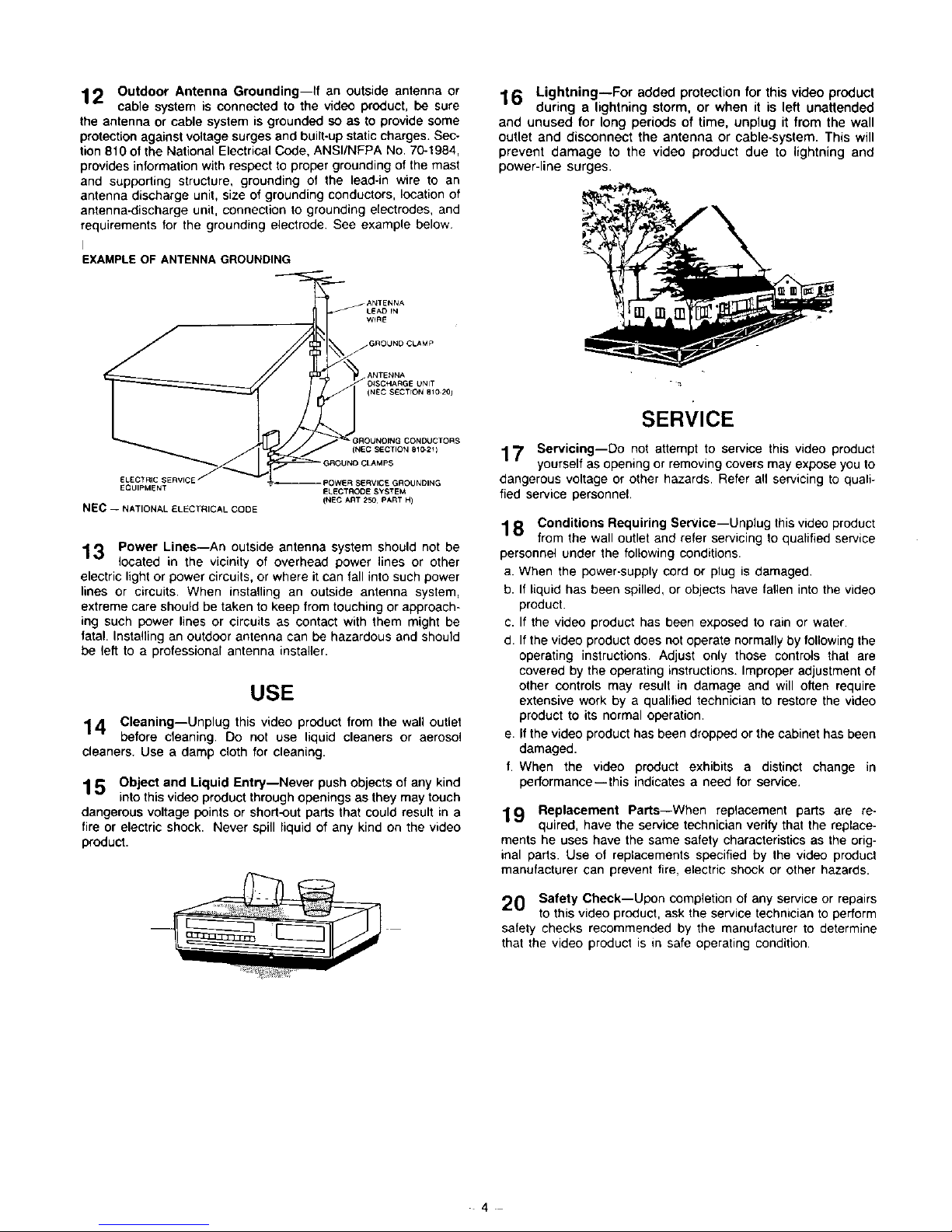
12 Outdoor Antenna Grounding--If an outside antenna or
cable system is connected to the video product, be sure
the antenna or cable system is grounded so as to provide some
protection against voltage surges and built-up static charges. Sec-
tion 810 of the National Electrical Code, ANSI/NFPA No, 70-1984,
provides information with respect to proper grounding of the mast
and supporting structure, grounding of the lead-in wire to an
antenna discharge unit, size of grounding conductors, location of
antenna-discharge unit, connection to grounding electrodes, and
requirements for the grounding electrode See example below
I
EXAMPLE OF ANTENNA GROUNDING
16 Lightning--For added protection for this video product
during a lightning storm, or when it is left unattended
and unused for long periods of time, unplug it from the wall
outlet and disconnect the antenna or cable-system. This will
prevent damage to the video product due to lightning and
power-line surges.
LEAD rN
W_RE
j GROLIND CLAMP
/ ANTENNA
O_SCHARGE UNIT
(NEC SECTION BI0 201
• GROUNOING COND4JCTORS
(NEC SECTION 810=21 )
ELECTRIC SERVICE POWE R SERVICE GROUNDING
EQUIPMENT ELECTROD E SYSTEM
(NEC ART 250 PART 14)
NEC -- NATIONAL ELECTRICAL CODE
13 Power Lines--An outside antenna system should not be
located in the vicinity of overhead power lines or other
electric light or power circuits, or where it can fall into such power
lines or circuits. When installing an outside antenna system,
extreme care should be taken to keep from touching or approach-
ing such power lines or circuits as contact with them might be
fatal. Installing an outdoor antenna can be hazardous and should
be left to a professional antenna installer.
USE
14 Cleaning--Unplug this video product from the wall outlet
before cleaning. Do not use liquid cleaners or aerosol
cleaners. Use a damp cloth for cleaning.
1 5 Object and Liquid Entry--Never push objects of any kind
into this video product through openings as they may touch
dangerous voltage points or short-out parts that could result in a
fire or electric shock. Never spill liquid of any kind on the video
product.
SERVICE
17 Servicing--Do not attempt to service this video product
yourself as opening or removing covers may expose you to
dangerous voltage or other hazards. Refer aft servicing to quali-
fied service personnel,
18 Conditions Requiring Service--Unplug this video product
from the wall outlet and refer servicing to qualified service
personnel under the following conditions.
a. When the power-supply cord or plug is damaged.
b. If liquid has been spilled, or objects have fallen into the video
product.
c. If the video product has been exposed to rain or water
d. If the video product does not operate normally by following the
operating instructions. Adjust only those controls that are
covered by the operating instructions. Improper adjustment of
other controls may result in damage and will often require
extensive work by a qualified technician to restore the video
product to its normal operation.
e. If the video product has been dropped or the cabinet has been
damaged.
f. When the video product exhibits a distinct change in
performance--this indicates a need for service,
19 Replacement Parts--When replacement parts are re-
quired, have the service technician verify that the replace-
ments he uses have the same safety characteristics as the orig-
inal parts. Use of replacements specified by the video product
manufacturer can prevent fire, electric shock or other hazards.
20 Safety Check--Upon completion of any service or repairs
to this video product, ask the service technician to perform
safety checks recommended by the manufacturer to determine
that the video product is in safe operating condition
4
IMPORTANTSAFETYINSTRUCTIONSFORAC ADAPTOR/CHARGER
1. Save these instructions -- This page contains
important safety and operating instructions for AC
Adaptor/Charger Model VM-AC64AS(M).
2. Before using AC Adaptor/Charger, read all instruc-
tions and cautionary markings on (1) AC Adap-
tor/Charger, (2) battery and (3) product using
battery.
3. Also read all instructions on pages 3 and 4.
4. Caution -- To reduce risk of injury, charge only
rechargeable battery, VM-BP64AS or 57-53982.
Other types of batteries may burst causing personal
injury and damage.
5. Do not expose charger to rain or snow.
6. Use of an attachment not recommended or sold by
the battery charger manufacturer may result in a
risk of fire, electric shock, or injury to persons.
7. To reduce risk of damage to electric plug and cord,
pull by plug rather than cord when disconnecting
charger.
8. Make sure that cord isproperly located so that it will
not be stepped on, tripped over, or otherwise sub-
jected to damage or stress.
9. Do not operate charger with damaged cord or plug
-- replace them immediately.
10. An extension cord should not be used unless ab-
solutely necessary.
Use of improper extension cord could result in a risk
of fire and electric shock. If extension cord must be
used, make sure:
A. That pins on plug of extension cord are the same
number, size, and shape as those of plug on
charger.
B. That extension cord is properly wired and in
good electrical condition; and
C. That wire size should be met below:
Minimum
AWG size
18
16
Length of extension cord (feet)
Equal to or less than 100
Equal to or less than 150
11. Do not operate charger if it has received a sharp
blow, been dropped, or otherwise damaged in any
way; take it to a qualified serviceman.
12.
Do not disassemble charger; take it to a qualified
serviceman when service or repair is required. In-
correct reassembly may result in a risk of electric
shock or fire.
13. To reduce risk of electric shock, unplug charger
from outlet before attempting any maintenance or
cleaning.
- 5

TABLE OF CONTENTS
Features ......................................................... 2
Accessories .................................................... 2
Important safeguards ...................................... 3
Important safety instructions for
AC Adaptor/Charger .................................... 5
Electronic viewfinder position adjustment ........ 7
Attaching the telephoto or wide-angle lens ...... 7
Loading battery for date/clock ........................ 7
Power sources ............................................... 8
Battery pack checking .................................... 9
Charging the battery pack ............................. 10
Making a sample camera recording ................ 11
Identification and operation of controls .......... 13
Auto focus ................................................... 19
Power zoom ................................................. 21
Macro lens ................................................... 21
Instant review ............................................... 21
Variable shutter speed ................................... 22
Auto iris ....................................................... 22
Recording TV program .................................. 23
Audio dubbing .............................................. 24
Video dubbing .............................................. 25
index signal recording ................................... 26
Date/clock setting ........................................ 27
Attaching the DC camera light ...................... 28
Title making ................................................. 29
Eyepiece adjustment ..................................... 31
Producing best color program ....................... 31
Viewing the picture played back
on your TV ................................................ 32
Display button .............................................. 34
Linear time counter ....................................... 34
Memory ....................................................... 35
Time remaining ............................................. 35
F-search and R-search ................................... 36
Pause ........................................................... 36
Edit search ................................................... 37
Operating hints ............................................. 38
Camera/Recorder to VCR dubbing ................. 38
Flying erase head .......................................... 38
Troubleshooting ............................................ 39
Storing the Camera/Recorder in the
carrying case ............................................. 40
Routine maintenance .................................... 41
Sears service ................................................ 41
How to order repair parts .............................. 41
Specifications ............................................... 41
Using the optional synchro edit cord .............. 42
"Note to CATV system installer: This reminder is provided to call the CATV system installer's attention to
Article 820--22 of the NEC that provides guidelines for proper grounding and, in particular, specifies that
the cable ground shall be connected to the grounding system of the building, as close to the point of cable
entry as practical".

ELECTRONIC VIEWFINDER POSITION ADJUSTMENT
The position of the ElectronicViewfinder can be adjusted so itcan be viewed with the left eye aswell as the right eye+
• When viewing with right eye • When viewing with left eye
ATTACHING THE TELEPHOTO OR WIDE-ANGLE LENS
Usethe Telephoto attachment if you wish to make your
subject appear larger or the Wide-angle attachment to
make your subject appear wider.
1. To remove Lens Hood, put hand flat against Lens
Hood and turn it counterclockwise.
\
2, Remove both caps of the Telephoto Lens or Wide-
angle Lens (Optional Accessories).
3. Screw the lens into the threads on the front of Video
Camera/Recorder lens assembly.
NOTES:
• Auto focusing will not operate correctly when the
Telephoto or Wide-angle lens is attached to the Video
Camera / Recorder.
• Shading at corners may occur near the Wide-angle
end (extreme of your zoom lens) and in the macro po-
sition.
LOADING BATTERY FOR DATE/CLOCK
You may want to install the clock battery IAccessow
No. 7) immediately to prevent misplacing it.
1. Poll the tab to open the cover and expose the
compartment.
2. Insert the clock battery with the "+" terminal facing
out (as illustrated inside the battery cover),
3, Gently push the cover closed until it snaps into place.
NOTES:
• When replacing the batteries, use 3V micro lithium
cell such as Maxell CR2025 or equivalent.
• Instructions for setting the time and date are on page
27. You can do that later if desired after you're more
familiar with your camera/recorder.
7
POWER SOURCES
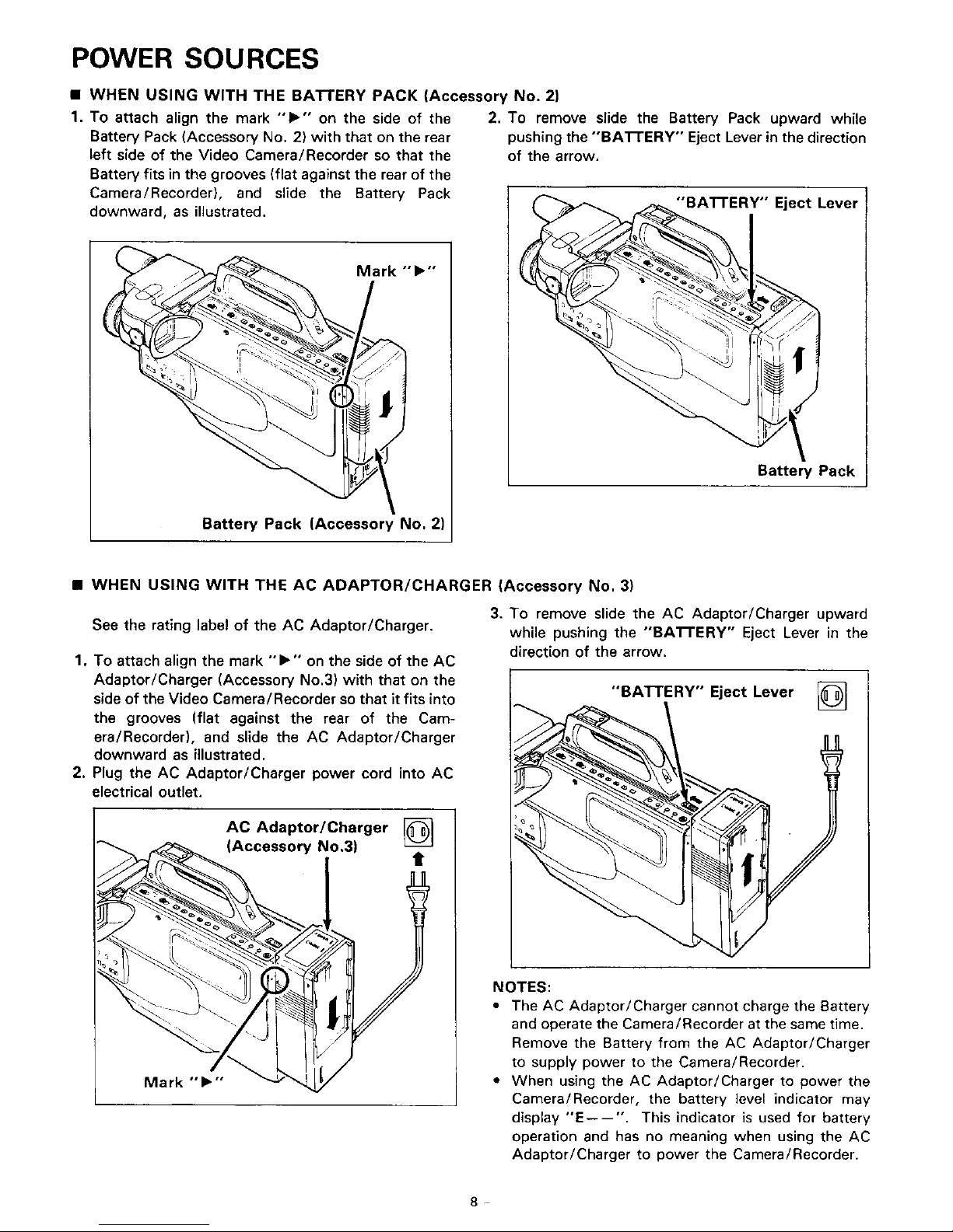
• WHEN USING WITH THE BAI-rERY PACK (Accessory No. 2)
1. To attach align the mark "1_" on the side of the
Battery Pack (Accessory No. 2) with that on the rear
left side of the Video Camera/Recorder so that the
Battery fits in the grooves (flat against the rear of the
Camera/Recorder), and slide the Battery Pack
downward, as illustrated.
Battery Pack (Accessory No. 2)
2. To remove slide the Battery Pack upward while
pushing the "'BA'I-rERY'" Eject Lever in the direction
of the arrow.
"'BA'n'ERY" Eject Lever
Battery Pack
• WHEN USING WITH THE AC ADAPTOR/CHARGER (Accessory No, 3)
See the rating label of the AC Adaptor/Charger.
1. To attach align the mark "1_" on the side of the AC
Adaptor/Charger (Accessory No.3) with that on the
side of the Video Camera/Recorder so that it fits into
the grooves (flat against the rear of the Cam-
era/Recorder), and slide the AC Adaptor/Charger
downward as illustrated.
2, Plug the AC Adaptor/Charger power cord into AC
electrical outlet.
AC Adaptor/Charger @
(Accessory No.3)
Mark ""I_'"
3. To remove slide the AC Adaptor/Charger upward
while pushing the "BA'B'ERY" Eject Lever in the
direction of the arrow.
"BATTERY" Eject Lever @
NOTES:
• The AC Adaptor/Charger cannot charge the Battery
and operate the Camera/Recorder at the same time.
Remove the Battery from the AC Adaptor/Charger
to supply power to the Camera/Recorder.
• When using the AC Adaptor/Charger to power the
Camera/Recorder, the battery level indicator may
display "'E----". This indicator is used for battery
operation and has no meaning when using the AC
Adaptor/Charger to power the Camera/Recorder.
8
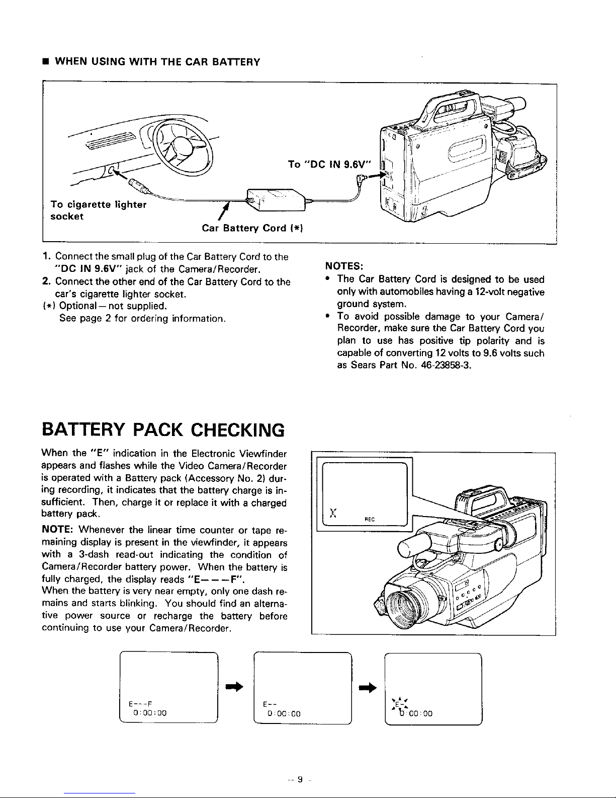
• WHEN USING WITH THE CAR BATTERY
To cigarette lighter
socket
Car Battery Cord (_)
To "DC IN 9.6V"
1. Connect the small plug of the Car Battery Cord to the
"DO IN 9.6V '° jack of the Camera/Recorder.
2. Connect the other end of the Car Battery Cord to the
car's cigarette lighter socket.
(*) Optional-- not supplied.
See page 2 for ordering information.
NOTES:
• The Car Battery Cord is designed to be used
only with automobiles having a 12-volt negative
ground system.
• To avoid possible damage to your Camera/
Recorder, make sure the Car Battery Cord you
plan to use has positive tip polarity and is
capable of converting 12volts to 9.6 volts such
as Sears Part No. 46-23858-3.
BATTERY PACK CHECKING
When the "E" indication in the Electronic Viewfinder
appears and flashes while the Video Camera/Recorder
is operated with a Battery pack (Accessory No. 2) dur-
ing recording, it indicates that the battery charge is in-
sufficient. Then, charge it or replace it with a charged
battery pack.
NOTE: Whenever the linear time counter or tape re-
maining display is present in the viewfinder, it appears
with a 3-dash read-out indicating the condition of
Camera/Recorder battery power. When the battery is
fully charged, the display reads "'E-----F".
When the battery isvery near empty, only one dash re_
mains and starts blinking. You should find an alterna-
tive power source or recharge the battery before
continuing to use your Camera/Recorder.
E---F
O:00:O0
E_-
O:OO:OO
• 'o'too:oo
9
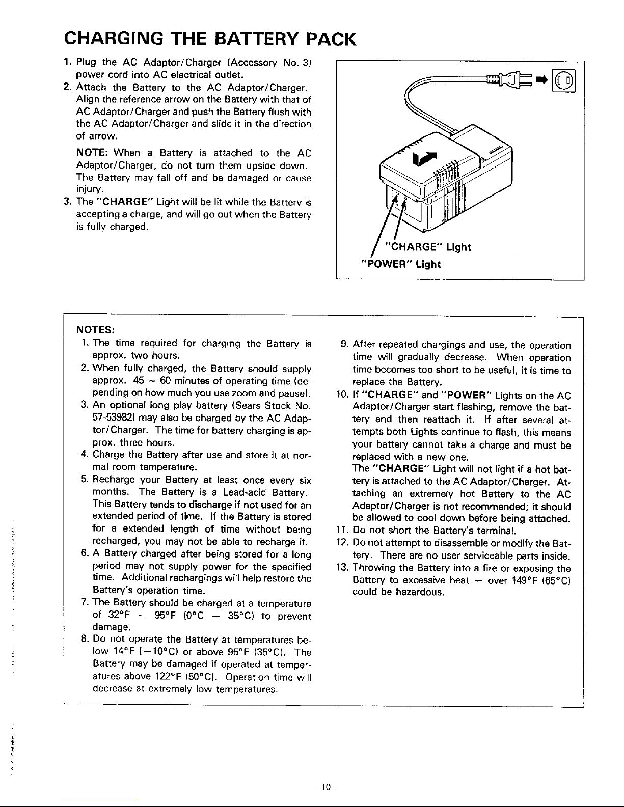
CHARGING THE BATTERY PACK
1.
2.
3.
Plug the AC Adaptor/Charger (Accessory No. 3)
power cord into AC electrical outlet.
Attach the Battery to the AC Adaptor/Charger.
Align the reference arrow on the Battery with that of
AC Adaptor/Charger and push the Battery flush with
the AC Adaptor/Charger and slide it in the direction
of arrow.
NOTE: When a Battery is attached to the AC
Adaptor/Charger, do not turn them upside down.
The Battery may fall off and be damaged or cause
injury.
The "CHARGE" Light will be lit while the Battery is
accepting a charge, and will go out when the Battery
is fully charged.
"CHARGE" Light
"'POWER" Light
NOTES:
1. The time required for charging the Battery is
approx, two hours.
2. When fully charged, the Battery should supply
approx. 45 - 60 minutes of operating time Ide-
pending on how much you use zoom and pause).
3. An optional long play battery (Sears Stock No.
57-53982) may also be charged by the AC Adap-
tor/Charger. The time for battery charging is ap-
prox. three hours.
4, Charge the Battery after use and store it at nor-
mal room temperature.
5. Recharge your Battery at least once every six
months. The Battery is a Lead-acid Battery.
This Battery tends to discharge if not used for an
extended period of time. If the Battery is stored
for a extended length of time without being
recharged, you may not be able to recharge it.
6. A Battery charged after being stored for a long
period may not supply power for the specified
time, Additional rechargings will help restore the
Battery's operation time,
7. The Battery should be charged at a temperature
of 32°F -- 95°F (0°C -- 35°C) to prevent
damage.
8. Do not operate the Battery at temperatures be-
low 14°F (--1O°C) or above 95°F (35°C). The
Battery may be damaged if operated at temper-
atures above 122°F (50°C). Operation time will
decrease at extremely low temperatures.
9. After repeated chargings and use, the operation
time will gradually decrease. When operation
time becomes too short to be useful, it is time to
replace the Battery.
10. If "CHARGE" and "POWER" Lights on the AC
Adaptor/Charger start flashing, remove the bat-
tery and then reattach it. If after several at-
tempts both Lights continue to flash, this means
your battery cannot take a charge and must be
replaced with a new one.
The "'CHARGE" Light will not light if a hot bat-
tery isattached to the AC Adaptor/Charger. At-
taching an extremely hot Battery to the AC
Adaptor/Charger is not recommended; it should
be allowed to cool down before being attached.
11, Do not short the Battery's terminal.
12. Do not attempt to disassembleormodify the Bat-
tery. There are no user serviceable parts inside.
13. Throwing the Battery into a fire or exposing the
Battery to excessive heat -- over 149°F (65°C)
could be hazardous.
!
10
MAKING A SAMPLE CAMERA RECORDING
1. Connect the POWER SOURCE. (See pages 8 and
9.)
2. Press "EJECT" Button and insert the cassette so
the transparent window is toward you and the
arrow toward the Cassette Holder. Slide the
Cassette into Cassette Holder as far as it will go.
NOTE: If the power source is not connected to
Camera/Recorder, the Cassette Holder will not
open.
3. Press the Cassette Holder. The Holder will latch in
the operating position.
"EJECT" Button
Cassette Holder
4. Set "VCR/CAM" Select Switch to "CAM"
position.
5. Press "POWER" ON/OFF Button on. The Video
Camera/Recorder will enter record/pause mode
automatically.
NOTE: If the erase prevention tab on the cassette
is removed or no cassette is inserted, "TAPE" in
the viewfinder will flash for several seconds and the
Camera/Recorder will not enter record/pause
mode and recording is not possible.
"POWER" ON/OFF Button
"VCR/CAM" Select Switch
6. Set "FOCUS AUTO/MAN" Switch to "AUTO".
NOTE: See page 31 for "EYEPIECE ADJUST-
MENT".
"FOCUS AUTO/MAN" Switch
7. Now, press Record Start/Stop Button to start
shooting the picture. "REC" indication appears in
the viewfinder and you are now recording the pic-
ture you see through the Electronic Viewfinder.
8. Press Record Start/Stop Button to stop recording.
Press the Button again to resume recording. The
"REC" indication in the Electronic Viewfinder goes
off in the record/pause (stand-by) mode.
Record Start/Stop Button
11
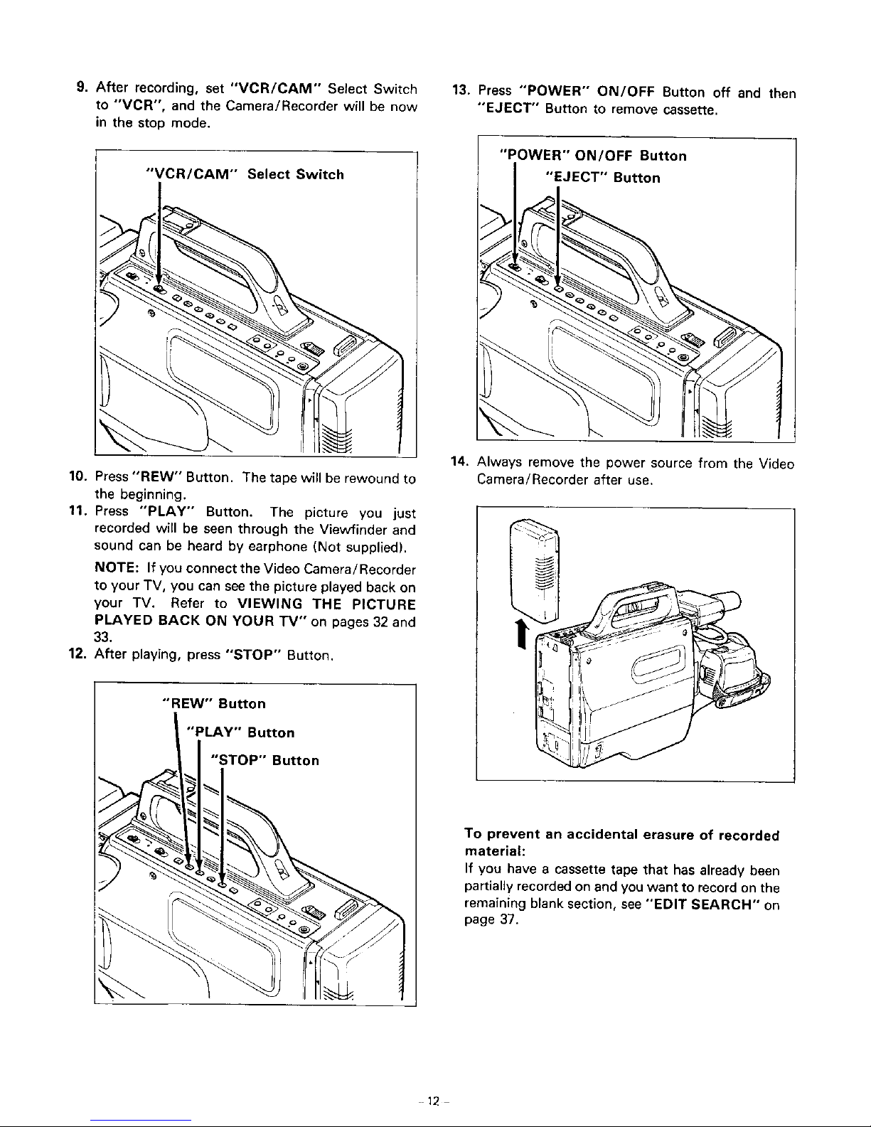
9. After recording, set "VCR/CAM'" Select Switch
to "'VCR", and the Camera/Recorder will be now
in the stop mode.
"VCR/CAM'" Select Switch
13. Press "POWER" ON/OFF Button off and then
"EJECT" Button to remove cassette.
"POWER" ON/OFF Button
"EJECT" Button
10. Press "REW" Button. The tape will be rewound to
the beginning.
11. Press "PLAY" Button. The picture you just
recorded will be seen through the View'finder and
sound can be heard by earphone (Not supplied).
NOTE: If you connect the Video Camera/Recorder
to your TV, you can see the picture played back on
your TV. Refer to VIEWING THE PICTURE
PLAYED BACK ON YOUR TV" on pages 32 and
33.
12. After playing, press "STOP" Button.
14. Always remove the power source from the Video
Camera/Recorder after use.
"'REW'" Button
"PLAY" Button
"STOP" Button
To prevent an accidental erasure of recorded
material:
If you have a cassette tape that has already been
partiallyrecorded on and you want to record on the
remaining blank section, see "EDIT SEARCH" on
page 37.
12
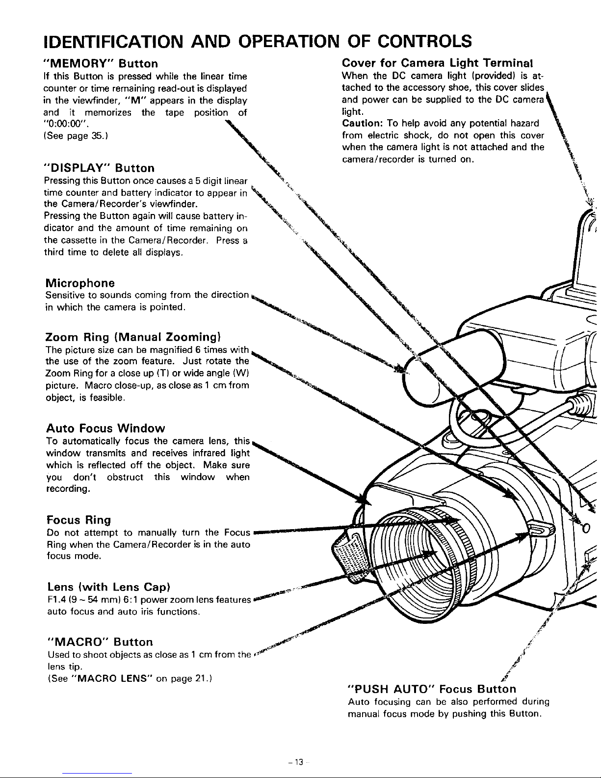
IDENTIFICATION AND OPERATION OF CONTROLS
"MEMORY" Button
If this Button is pressed while the linear time
counter or time remaining read-out is displayed
in the viewfinder, "'M" appears in the display
and it memorizes the tape position of
"0:00:00", "_%.;.
DISPLAY" Button "_
Pressing this Button once causes a 5 digit linear "_
time counter and battery indicator to appear in _-_
the Camera/Recorder _s viewfinder, "_.
Pressing the Button again will cause battery in- "_
dicator and the amount of t me reman ng on _
the cassette in the Camera/Recorder. Press a
third time to delete all displays.
Cover for Camera Light Terminal
When the DC camera light (provided) is at-
tached to the accessory shoe, this cover slides
and
power can be supplied to the DC camera _,
light. _.
Caution: To help avoid any potential hazard _,
from electric shock, do not open this cover _,
when the camera light is not attached and the _.
camera/recorder is turned on.
\
Microphone
Sensitive to sounds coming from the direction
in which the camera is pointed.
Zoom Ring (Manual Zooming)
The picture size can be magnified 6 times with
the use of the zoom feature. Just rotate
Zoom Ring for a close up (T) or wide angle (W)
picture. Macro close-up, as close as 1 cm from
object, is feasible.
Auto Focus Window
To automatically focus the camera lens, this,
window transmits and receives infrared light
which is reflected off the object, Make sure
you don't obstruct this window when
recording.
Focus Ring
Do not attempt to manually turn the Focus
Ring when the Camera/Recorder is in the auto
focus mode,
Lens (with Lens Cap)
F1.4 (9 - 54 ram) 6:1 power zoom lensfeatures =_=_'_
auto focus and auto iris functions.
"MACRO" Button ,j"
Used to shoot objects as close as 1 cm from the,
lens tip.
(See "MACRO LENS" on page 21.)
,/
/
"PUSH AUTO" Focus Button
Auto focusing can be also performed during
manual focus mode by pushing this Button.
13
 Loading...