

Page 1
SEARS
OWNERS
MANUAL
MODEL NO.
919.154020
919.154120
919.154320
919.154420
Listed
Air
compressor
IMPORTANT.,
Read the Safety Guidelines
and All lnstruott0ns
Carefully Before Operating
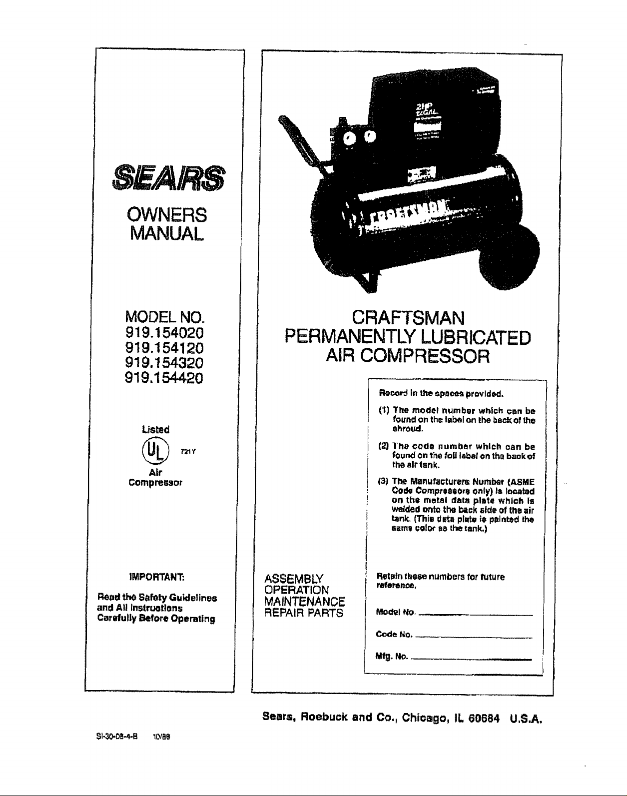
CRAFTSMAN
PERMANENTLY LUBRICATED
AIR COMPRESSOR
Record in the spaces provldc_L
(1) The model number whl<;h _un be
found on the laber on the ba¢_ of the
Shroud.
(2)
The code number which oan be
fourKJon the fob label on the baok of
the air tank.
(3)
The Manufacturers Number (ASME
Code Compre880r_ Only) Is locatsd
B
on the motel data plate whl©h is
v_ded onto the I_ck _fde of the air
i
tzn_, (Thia ¢eta plzrbpi= painted the
iseme_elOr aS the tank.)
ASSEMBLY
OPERATION
MAINTENANCE
REPAIR PARTS
Pvatafnthese numbers for future
refePen_,
Model No.
Code No.
S)-30-_..4,.B lotae
a_. No.
Sears, Roebuck and Co,, Chicago, IL 60684 U,S,A,
Page 2
TABLE OF CONTENTS
Page
WARRANTY ......................................................... 3
SAFETY GUIDELINES ................................................ 3
WARNING CHART ....................................................... 3
SPECiRCATION CHART ................................................ 5
GLOSSARY ................................................................... 5
ACCESSORIES FOR USE W!TH SEARS AIR COMPRESSORS ,, 6
GENERAL INFORMATION ............................................. 6
DESCRIPTION OF OPERATION .................................. 6
ASSEMBLY INSTRUCTIONS ............................................ 7
ToolsN_¢C!edforAss_mbty.............................................. 7
Installing Wheels, Handle, Rubber foot strip............................... 7
Installing Regulator .................................................... 7
INSTALLATION AND BREAK-IN PROCEDURES .......................... 7
location ofAir Compressor............................................. 7
Lubric,_ttonand 0it ..................................................... 7
_._t_'_fon Cord_ ....................................................... 7
GroundingInst_'uctions.................................................8
greak-lnProcedures....................................................8
OPERATING PROCEDURES ........................................ 8
MAINTENANCE .........................................................g
Air _Iter ..............................................................9
Check V_tve- Repl_ceme_ ........................................... 9
Safety _aJve - Inspection ........................................... 8
Motor...................................................................9
STORAGE ..............................................................lo
TROUBLESHOOTING GUIDE ........................................ 1o
AIR COMPRESSOR DIAGRAM ...................................... t:2
Part,=,List .................................................................... 13
COMPRESSOR PUMP DIAGRAM .......................................14
ParlSList........................................................15
HOW TO ORDER REPAIR PARTS ........................................ 16
Page 3
FULL ONE YEAR WARRANTY
AIR COMPRESSORS
Ifthisair compressorfailsdueto a defect Inmaterialor workmanshipwithinone year fromthe
date of purchases.RETURN IT TOTHE NEAREST SEARS SERVICE GENTERtOEPARTMET,_r
THROUGHOUT THE UNITED STATESAND SEARS WILL REPAIR IT,FREE OF CHARGE,
ifthisair compressorisused for commercial or rentalpurposes,the warrantywill apptyfor nlnety
days from the date of purchase.
Thiswarrantygives you specificlega{ rights and you may have other nghtswhich vary from state
tostate..
Sears, Roebuck and Co. Sears Tower, Dept. 6_1/731A, Chicago, 1L60684
SAFETY GUIDELINES
Thtsmanualcontainsinformation that is importantfor you to knowand understand,ThisInforma-
tionrelatesto protectingYOUR SAFETY and PREVENTING EQUIPMENT PROBLEMS To help
you recognize this information, we use the followingsymbols°Pleaseread the manual and pay
attentionto these sectlort._.
URGENT SAFETY INFORMATION ,- A
HAZARD THAT WILL CAUSE SERIOUS
INJURY OR LOS_; OF LIFE,
information for preventing damage to
equipment,
HAZARDS CAN OCCUR IF EQUIPMENT tS NOT USED PROPERLY,
PLEASE READ THE FOLLOWtNQ CHART,
WHAT TO
LOOK FOR
Hot Parts
Flammable
vapors
WHAT COULD HAPPEN
The compressor heed gets hot when the air
compressor Is running. Ifyou touchit, you may
be seriously bumecL
Itisnormalforthe motor and pressure switchto
spo.rt_when operating, if the v_pors from
gasoline or other solvents come into¢onte=¢t
w!ththesparks,theymayignite and c&usea fire
or explosion
IMPORTANT SAFETY INFORMATION - A
HAZARD THAT MIGHT CAUSE SERIOUS
INJURY OR LOSS OF LIFE.
NOTE
informationthat you should pay specialat_en-
lion to.
HOW TO PREVENT IT
Never touchthe air compressorhead during or
immediatelyafter opert_tion_
,,H,,,I,,, ,,i,, i, ,,/ ..... :
Always operale the air compressor in well-
ventit=_d 8r€1_5:free ot ga3o_Jrt_or artier_oJv_t
vapors, Do not operate the coml:_essornear the
spray area
Page 4
W.ATT0
LOOK FOR
WHAT COULD HAPPEN
HOW TO PREVENT IT
Nr Tank
Compassed Air' Cornpr_'_ed sir can propeldust,dirt.or loose
Eie ty
Modifications to the air compressorcan cause
the air tank to rupture orexplode,
Changingthe air tank will cause It to weaken.
The tank may rupture or exp!ode_
partio[esit comes in contactwith,
Too much air pressure applied to air toolsor
accessories cart cause damage or risk Of
bursting.
Yourair compressorIs poweredby electricity.
LikeanyothereleGtdcaJlypDwereddevice,ifitis
notusedproperlyIt maycauseelectdeaJshock
Do not adjust, remove or tamper with the safety
valve orpressureswitch. Ifsafety valveorpressure
switch r_e=emen_ ;s necessary,a part withthe
same ratingmust be used
Never useamot0r withahlgher horsepower rating
thanthe one supplied.
Never replacetheair lan_ witha differentmo0el or
a large_tank,
N_er ddlt{n_o,weld, or inany way modily the air
tank,
N_werpolntany nozzfeorsprayertoward a person
or anypart of the body,,
Always wearsafety gogglesOrglasseswhenusing
the air compressor,
AF,,_ys turn the air compressoroff beforeattach-.
ingorremovingaccessories,
Che_kthe m.anufactuter's m_(mum pressurerat-
ingfor air tools 9.ndaccessories.Rsguta_r outlet
pressure must never exceed the maximum_¢es-
sure rating.
Always unplug t!le air compressor prior1omalrtte-
nonce ot repair,
Never use the air compressoroutdoors when it is
r_ning.
ToxicVapors
UnsuJtat_fe
Solvent=
4
I!iS_rmal for€ompressedalr_containtoxicor
irritating vapors.8uoh vapor's are harmful if
inhaled.
Certain materials you are spraying(like pairrl,
weedkiUe(sandorinsecticide)may beharmful
If you Inhalethem,
The solvents!,t,1 - Trich!omethane M'elhy-
lena ChlorideCanchemlc_.tly react with alumi-
numu_edinpaintspray g_Jr_,paintpumps,etc..,
and cause an explosion These solventscan
also react with galvani=od components and
cause corrosionand weakeningof paris. This
does _lotaffect youraircompressor_but it may
affect the equipmentbeing u_d,
and
Always I_Ugthe cord intoan ale€tricotcutter with
the specified voltage and adequate fuse
p_teetfon,
Neverdlrect|yInhale_hecompressedairproduced
by thisunit.
Read and follow the safety Instructions provided
on the i_bel or safety data sheetfor the matetla[
you arespraying.Usea respiratorma_kilthere tsa
chance of tnh_tlng anything you are spraying,
Read =t instructions.., be ¢un_that the r_l_iral_r
maskis sultabte foryour application.
Ifthe material youintend1ospraycontainsthe sol-
ventsltSledatl_ft [read thelabel ordale sheet},do
not u_ accessoriesthatcontain aluminumor g_u-
vanlze_ part=.Youmusl eitherchang_ themateria_
you intend to spray, or use only stafnle=s _teel
spray equipment,
Page 5

SPECIFICATION CHART
Mo_I No.
Horsepower
DisplacementCFM
Bore
Stroke
Voltage.SinglePhase
MinimumBranch CircuitRequirement
"'Fuse Type
Air TankCapaclty
Approximate Cut-inPressure
ApproximateCut-outPressure
SCFM C_40 psig
SGFM ('.490 psfg
These compre_ors can be operated on a 15amp Glrcutt if:
1.Voltage supply to clr=uit is normal.
2, Ciroutt Is not used to supply any otl_r electrical needs (lights, appliances, etc.)
3. Extension r._rds comply with specifications in owners manual.
4. Clrouit ts equipped with 15amp otrcuit breaker or 15 amp Fuset_ronType "T" time delay tuse_
If any of the above conditlorm cannot be met, or if operation of the compressor repeatedly causes
Interruption of the power It may be necessary to operate it from a 20 amp €ircuit. It is not necessary to
919.154020 919.1_20 919J54120 919.1_4420
2 2 2 2
I0,0 100 t0,0 10,0
2%" _1/t" _=_" _'_"
1,13'° 1.13" 1,,13" 1.13'
t?.0 120 12.0 t213
"15amp_ "15arnps "15amps ÷15amps
"Fusetron" "Fusetron" "Fusetron" "Fusetmn•
•"TypeT "Type T "Type T **Type T
t2 g_L 20 gel, 12gel ASME 20 gal.ASME
80 80 80 80
100 100 _00 I00
70 7O 7,0 70
5,6 5.8 5.6 5.6
changethe cord set.
"'A circuit breaker iepreferred. Use only a f,._seor circuitbreaker thatis the same ratingas the branch circuitthe air
compressortsoperatedon. II the air compressorIs conr_oled to a circuitprotectedbyfuses, use dueJelementtime
delay fuses (Buss FuestronType"T" onty)
GLOSSARY
CFM: Cubicfeet per minute.
SCFM: Standardcubicfeetperminute:aunitof meas-
ure of_Jrdelivery.
PSlG: Poundspersquareinch gauge;a unitofmeas-
ure of pressure,
ASME: American Societyof Mechanist Engineers;
made, tested, inspected and registeredtomeet the
stanches oftheASME,
U.L LISTED: S_mplesol compressor outfits, taken
from production,w_re submitted to U.L and found to
comply with their requirements for design and
performance.
Cut-In Pressure: While themotor isoff, airtankpres-
sure dropsas you continue to use yourae,ces_ory.
Whenthe_ankpressure drops toacertainlowlevellh_
motor wltlm-s_rt autorr=atioaJly.The low preesureet
which themotorautomatically re-startsis called'cuF]n
pre_ure".
Cut-Out Pressures: Whenyou turnonyauraircorm
pressorand it beginstorun,eirpressureIn theeirtank
begins to build, tt builds to a certain high pressure
beforethe motor automaticallyshulsoff - protecting
your air tank from pressurehigherthan its¢_paclty.
The highpressureat whichthemotor shutsOffiScalled
"cut-out preesure'L
ACCESSORIES FOR USE WITH SEARS AIR COMPRESSORS
The followingaccessoriesare availablethroughtl_ecurrcnt general sales catalog or at full-line8cars stor_,
. SPRAY GUNS
• BLOWGUNS
• AIRCAULKINGGUNS
• AIR POWERED WASHER GUNS
"SANDBLASTERS
•AIR BRUSHES
- AIR LINE FILTERS
, TiRE AIR CHUCKS
" PAINTTANK,._
, AIR TANKS
• INFLATER KIT_i
• QUICK CONNECTOR SETS
(various sizes)
•VISCOSIMETER
, AIR PRESSURE REQULATORS
•OIL FOG LUBRICATORS
. AIR TOOLS:
Sanders
Dfifis
tmpact wrenches
Hammers
• AIR HOSE;
W', %e"or% '_I.D.
in variOuSlengths
Page 6

GENERAL
INFORMATION
Youhavepurchasedan aircompressorunitoonsisilngof
a 1 _'lir',der, sing_staga air compressorpump,an air
tank,air hose,wheels, handle, and associatedcontrols
Youwillalso lindan air chuck.
T'-_saircompressor requiresno oil, Now you can enjoy
all the benefffsof having an air compressorwltl_outever
havingtopurchase,add or change oil
DESCRIPTION OF OPERATION
Your air compressorcan be used for operating paint
sprayguns, air loois, caul_ng guns, grease guns,air
bruohes, sandbtaBtens,or inflatingtiresand plasticto_p_,
sprayingweed klllers, insecticides,etc.
_p_ra_e air tran:dormerswhichcombine the functions
ofair regulptionand/ofmoistureanddirtremovalshould
beusedwhereapplicable.
Air Compressor Pump: To compress air, the piston
moves upand downIn thecyllt_te_oOnthe downstroke,
aimsdrawninthroughtheair intakevalves,The exhaust
valvererr_lnsctose_t.On theupstrokeofthepiston,a{ris
compressed. The intakevalves €_o=e_nd compressed
air isfor_edout throughthe e_haus!valve, throughthe
outlet tube,lhmugh thecheckvalveand intotheair tank,
Workingair is not _vallable untl_the compressorhas
raisedthe airtankp_essureabovethatrequired at the air
_utlet.
Check Valve;Wh_ file aircompressorIsoperating, I._e
chock v_Jvo(s "open",allowing compressed airto enter
theaft tank.Whenthe aircompressorreaches"cut-,out"
pre_eure,the checkvalve"=loses", allowing airpressure
tOn_m=tnInside the air tank,
Preaaure Releue Valve; The pressurereleasevalve
located on thesideofthepressureswitch, is designedto
automatically release compr_8Od air from the com-
_essor ha_d and the outlet;tube whenthe _ir compres-
sot reaches"cut-out" pm_;_ or is _hutoff, If theair Is
notreleased, themotorwilltry to=t¢,rt,but wigbe unable
t_.Thepressurerel_=sevalveallows the motortor_._r t
freely.When them_tor stops running,air willbe heard
escapingfromthevalveforafewseconds.Noair should
be heardleaking whenthe motor is running,
D_JU_C_K
the f_otoryeel "¢ut,-in"pressure,tt _ops the motorwhen
the air tank pressurereaches thefactory set =cut-out"
pmssL_e.
Safety Valve: Ifthepressure=witchdoes notshutoffthe
air compressor at itscut-outpressuresel_[ng,thesafety
valvewillprotectagainsthighpressureby'"poppingout_'
at iLspre-set p_ss_re.
Regulator: The air pressure comingfromthe air tan_ is
controlled by the regulator knob, Turn the knob
clcckwlseto incn_e pressureand counter.clockwise
todecreasepressure.To_rvoldminorre_djuslmentafter
ma_ng a change in pressures_tttng, alwaysapproach
the desired pressure from a i_wer pressure. When
reducing1tOma h_gherto a lowersetting,flintred_celo
some pressuretessth_n that desired,then bringupto
the desired pressure,.Dependingontheairrequirements
of e_,ch particular accessory, the out(at regulated air
pressUr_may h_v_ to be adjustedwillie oper_ting
_ccessory,
Outlet Prauurl Gauge: The outlet pressuregauge
indicates the air pressurea'_aJlab_e_t theou_letsideof
the taguiatOr,ThL_pressureis controlledbytheregulator
and is atways less or eq_Jalto the tank pressure.See
"Operating Procedures,,"
Pressure Switch: The presSureswirchautomatically
start_themotorwhenthesir tl_,rtkpressuredropsbeiOW
5
l_nk Pmuure Gauge: The tank pressureg_uge indi-
o_tes the refer'tinairpressureinthet=nk,
Page 7

ASSEMBLY INSTRUCTIONS
Tools Needed for Assembly
*pipethreadsealant(not incJuded)
, an a,clJustable wrench for attaching the pressure
regulator
"a _t_0,socket or open end wrench forattaching the
wheelsand hose adaptan
"a 7/1_openand wrenchfor attaching theair pressure
gauges
, a _e °'he,v.Re'i"for Installing the pluginthe regulal_
, a %" open end wrenchtotightenhandlescrews
"s #2 philtipe screwdriver for attaching the control
cover
installing Wheels, Handle, Rubber Foot Strip
i WARNIN_ !
THE WHEELS AND HANDLE OO NOT PRO-
VIDE ADEQUATE CLEARANCE, $TABJLITY
OR SUPPORT FOR PULLING THE UNIT UP
AND DOWN STAIRS OR STEPS, THE UN[T
MUST I_ELtFT]_D,ORPUSHED UP A RAMP.
1. Dipthe handle grip Insoapywaterandsttdeintoposi-
tionas shownon photoon page 6 orpage 12.
2, Attachthe handleto the insideofthecompressorsad-
diebyp_jshtngthe handleIn,unllitheslotinthehandle
engageswith the labs in the saddle,Pufithe handle
bsckar<l installthe two s<z_ws,one oneach sideof
the_e_ldte.Tightensecurely,
3- Rsmove the protectivepaperstrip frOmth_adhesive
backed rubber footstrip,Attachtherubberfootstrip to
thebottom of 1heairtitnkleg. Press firmlyintoplace°
4. Attachone wheelto each sideof the air ¢omp_ssor.
Use one shoulder bott and one nut for each wheel,
Tightensecurely.
Installing Regulator
Use a small amountof,pipe threadsealant on aJipipe
threadjoints.
Installthe regulatoron 1heendof lhe manifold using the
short pipe nipple. The arrow on the bottom ol the
regulatOrmustpoi_ away from the manifold in order fo_
theregulatortofunctionproperly,
_nstalithe adapterand plugIn the regulator,,The plugis
supplied withtheregulator,Installthe rearcoverandthe
gaugesat thesame time,See diagrambelow,
ittory be necemury to brace or support one
enU of the outfit when attaching thewheels
end the r_Jbber foot _trlp,because the air
compressor will have a tenden=y to tip.
INSTALLATION AND BREAK-IN PROCEDURES
Locationofthe Air Compressor
Loca4ethe air compressorina ctean,dry endwelJventi-
lateclarea.The air filler must be kept clearo'l obstruc.
tlons which could reduce air delivery of the air
compressor.The air compressorshould be locatedat
least12' away'fromthe wail or other obstructionsthat
wl!linterferewiththeftow ofair.Theaircompressorhead
and shroudaredesigned to al!ow forpropercooling.,If
humidity Is high a _ears air filter can be installed iD
remove excessive moisture. Follow the instructions
packaged withthe airfilter for proper installation,
LubricationandOil
Thtsunit n_eas no adcllttonallubrication or otling
R_ULATED
PRESSURE GAUG_
tnstallthe control_over. FastenIt to the manifoldusing
thephillipsscrew.Installthe plasticmounting ringtothe
regulatortofastenthetopofthecontmtcover,See photo
on page 6.
TANK
PRESSURE GAUGP-
Extension Cords
Useextre,air hose insteaxJOf_nextensioncordto avoid
voltagedrop and power loss to the motor,
tf an axlet_sloncordmust t_ us'_, be sum itis:
. a 3-wire ext_._ion cord that h_ a _-,bladegrounding
pll_, end !_3-_lotreceptacletigatwl!laccepttheplugon
the product,
. t_ good condition_
• no longerthan_50f_t.
.12 gtlUge (AWG) or larger. (Wire size increases as
gaugenumber _lecreaseso10 AWG and 8 AWG may
atsol_eused,OO NOT USt_t4 or 16AWG_)
Page 8

Grounding Instr,JcUons
L_ i
IMPROPER GROUNDING CAN RESULT iN
ELECTRICAl. SHOCK. IN THE EVENT OF A
SHORT CIRCUIT, GROUNDING REDUCES
IHE RISK OF SHOCK BY PROVIDING AN
ESCAPE WIRE FOR THE ELECTRIC CUR-
RENT. THIS AIR COMPRESSOR MUST BE
PROPERLYGROUNDED.
1.The air compressortsequippedwlthacord havinga
groundingwire with an _ppr_priate groundingplug.
The plugmust be usedwith an outletthat has been
installedand groundedin accordance wi_hall IocaI
codes and ordinances, The out_etmust have the
_aJ'_econfigurationas the plug. DO NOT USE AN
ADAPTER,
2, Do notmodify the plug1hathas been provided.!! it
does not tit the available outlet, the correct outlet
shoutdbe installedby a qualifiederectrician
3 inspectthe plugandcordbeforeeachuse_Donotuse
ifthereare signsof damage,
Ground
" Wire ""
GROUNDING ,,2" L..------J
PIN
120 vOltS,i5 amps
Break-In PrOc_ums
Serious damage moy _glt If_I'KIfoll_ing
break-in tnatructrono =r==not closely
followed.
Thisprocedureisonly _quir-ud the firstlimethe=Jrcom-
preSSOriSputintoserwce,
1.Set the swlt_ OFFtAUTOleverto the'OFF'
poetriespressure
RISK OF ELECTRICAL SHOCK, IF REPAIR-
ING OR REPLACING CORD OR PLUG, THE
GROUNDING WIRE MUST BE KEPT SEPA-
RATE FROM THE CURRENT.CARRYING
WIRES, NEVER CONNECT THE GROUND,
tNG WIRE TO A FLAT BLADE PLUG TER-
MINAL (THE GROUNDING WIRE HAS
INSULATION WITH AN OUTER SURFACE
THAT IS GREEN - WiTH OR WITHOUT YEL-
LOW STRIPES.)
if these grounding ine_ru_Uonsare not completely
unclerstood0orifIn doubtas towhether[hecompressor
is properlygrounO_d,havetheinstall=ioncheckedby a
qualifiedelectrlclan_
OPERATING PROCEDURES
1,Beforeattaching aJrhose oraccessories, make sure
the OFFtAUTO lever is set to "OFF" and the air
regulatorIs closed (Close it by turningit counter-
ClOCkWiSe)
2_At_chhOSe_ndaocessorfes.
WARNING
1"OOMUCH AIR PREgSURE CREATES A
HAZARDOUS RISK OF BURSTING, CARE-
FULLYFOLLOWSTEPS 3 AND 5 EACH TIME
THE COMPRF-_SOR IS USED.
2 Plug the.power c_ordinto the (;orrectbranc;hcimUit
receptacJe,
3 Turnthe regulatorc!oc.kw'L_,e,,openingit fulIy,to pre.
ventmr pressureI:_uz=o-up=nthetanK,
4_Move *,heOFF!AUTO leverto"AUTO'. Th_ compres-
sorwltIstarL
5, Run _he compressorfor 10 minutes, Make surethe
rupegulatorIsopenand them is no tankpressure build- ,_
6 After 10 rnin.utes,_ose t,heregultttorby lurning it
counter-c_oc:Kwise,fne _urtankv_lIfill_ OJt-,outpres-
sure andlhanthe rno_r Will510p
COMPRESSED AIR FROM THE OUTFIT MAY
CONTAIN WATER CONDENSATION. DO
NOT SPRAY UNRLTERED AIR AT AN ITEM
Tl1AT GOULD B_ DAMAGED. SOM F AIR
OPERATED TOOLS OR DEVICES MAY
REQUIRE FILTERED AIR. READ THE
INSTRUCTIONS FOR THE AIR TOOL OR
DEVICE,
.
Checkthemanufacturer'sm_lmum preserve_ating
for air tools and accessories, "Theregulatoroutlet
pressuremustneverexceed themaximurnprB_$ure
_at]ng.
Page 9

4. TurntheOFF!AUTO le._r to "AUTO"andallow Tank
pressureto _,Jlld,Motorwill6toowhentankpresmure
reaches"Cut-out"pressure.
S Open theregulatorby turningit clockwise Adjustthe
regulatortothecorrectpressuresettJng,Your com-
pressor{=readyfor use.
6. Alwaysoperalethe aircompressorInwell-ventilated
areas;freeof gasoline or other solventvapors Do
notoperatethecompressor near the spray area.
,Whenyou are finished:
7. Setthe "OFF-AUTO"leverto "OFF",
8. Turntheregulatorcounter-clock.viseand settheout_
I_ pressuretOz_ro,
9oRemovetMeair tooloraccessory,
!O.Openthe,'_egutatorandallow the airto slowlybleed
from theta.,'P_Close the regulator when tankpres_
sumis approximately 20 psi.
MAINTENANCE
UNIT CYCLES AUTOMATICALLY WHEN POWER IS ON. WHEN DOING MAIN_=.NANCE, YOU MAY
BE EXPOSED TO VOLTAGE SOURGESt COMPRESSED AIR OR MOVING PARTS. PERSONAL
INJURIES CAN OCCUR.BEFORE PERFORMING ANY MAINTENANCE 0 RREPAIR,UNPLUG THE
COMPRESSOR AND BLEED OFF ALL AIR PRESSURE,
1t, Drainwaterfromair tank,
WATERWILL CONDENSE IN THE AIRTANK.
IF NOT DRAINED, WATER WILL CORRODE
AND WEAKEN THE AIR TANK CAUSING A
RISK OF AIR TANK RUPTURE.
With tank pressurest approximately20 psi,, open
theclan cock and allowmoisture to d_n.
NOTE
If drain cock valve Is p_ugged,releaseall air pros-
sure.Tile valvecanthenbe removed,cleaned,then
relnst=lled
!2o After thewater has been drained, olose the drsln
e.ock.Theair compressorcan now be stored.
Atr Filter- Inspection
NOTE
Keepthe airfiltercleanat all times Do notoper-
ate the compressorwiththe airfilter removed,
A dirty air filterwillnot a.llowthe compressortooperate
at furlcapacity°Beforeyouuse the compressor,check
the air filter to be sum itis clean_
If ittsdirty,simplypullitout.Youmaywashit witha mild
detergentandwarmwater,or repiace It,
Check Valve- Replecement
1. Release afl air pressure fromaTrlanf<and unplug
outfit.
2. Removeshroud,
3, Loosen the topand bottom nuts and remove the
outlet tube.
4. Removethepressurerelease tubeandfitting,
5oUnsorewthe chec_ valve (turn counterclockwise]
usinga=ockel w_nch.
6 ChScK_at the valve _Isc moves treaty inside the
chiCk:valveandthat thespring hOidSthe disc tn the
upper, €!o=_1 position.The check valve may be
cleaned with a solvent, such as paintand varnish
remover,
% ApplyaQeJentto the checkvalve threeels Reinstall
theoPm¢_y=lvo(turn _lockwioe),
8, Replace the pressure release tubeand fittfng.
9, Replaoetheoutlet t',,=_)e€,ndtightenlop end bottom
nu_s.
!0, Rep!_cethe6hrOUd_
Safety Valve - Inspection
IF THE SAFETY VALVE DOES NOT WORK
PROPERLY, OVER-PRESSURIZATION MAY
OCCUR, GAUSING AIR TANt_RUFrTUREOR
AN EXPLOSION. OCCASIONALLY PULL
THE RING ON THE SAFETY VALVE 1"O
MAKE SURE THAT THE SAFETY VALVE
OPERATES FREELY. IF THE VALVE iS
STUCK OR DOES NOT OPERATE
SMOOTHLY,IT MUST BE REPLACED WITH
THE SAME TYPE OF VALVE.
Motor
The mow hasan automaticresetthermal overloadWo-
tenor. Hthe motor overheatsfor anyreason, the over-
ioa_ i)rot=_or will shutOffthemotor. The _ must be
allowed to ¢ool€lownbeforerestarting,The comFessor
•willautoma.ticallyre-start after the motor oools,
Ifthe overtoadprotectorshutsthe motor off kecluently,
d_ci( fora possiblevoltageproblem, Low vOltagecan
also be suspectedwhen:
t.,_e motor aoe_ not get up tofull power or speed;
2_fuses blow outwhenstarlingthe motor;,lights dimand
remaindimwhen motor is started and is running.
Page 10

STORAGE
Beforeyoustoretheair compressor,makesureyou do
thefoflowlng:
1,Reviewthe'Maintsr_n_e" section onthe precaeding
pages and perform maintenan;e as necessary, Be
sure to drainw=terfromthe airla_k.
TROUBLESHOOTING GUIDE
PERFORMING REPAIRS MAY EXPOSE VOLTAGE SOURCES_ MOVING PARTS, OR COM-
PRESSED AIR SOURCES. PERSONAL INJURY MAY OCCUR. PRIOR TO ATTEMPTING ANY
REPAIRS UNPLUG THE AIR COMPRESSOR AND BLEED OFF TANK AIR PRESSURE.
PR0.u .
Ex_essk,e _r_ pressure
safety valve Pol_soff,
Air leaks at fittings
Airleaks at checkvalve.
Airl@ak,_at pressure
_ltoh releasevalve
...... cause............................CORR T .
Pressureswitchdoesnot shut olt" Move thepressureswitohleverto_e "OFF'IPo_i-
motor when compressorreaches lion.if the OUtfitdoesn 1 shut off, an_lthe eleotricai
"cut-oUt"pressure, conlactsarewelc_edtogether,replacethepressure
Pressure switch "cut-out" tao Returnttleputfitto Sears ServleeCente_tocheck
high, anti aclju=,or replace switch,
ui, , .i. ,., , ...............................
Tubafiffingsare not_ht enough. Tightenfittingswl_re air can be he_a_esCaping_-_
Defectiveordirty check valve. A defective check valve resultsIn a constant air
Defective pressure_witch
roleasevalve.
2. Protectthe etectficaJcordandair hosefromdamage
(such s8 _:>etOgstepped on or _n over).Wind them
looselyamUr_l_the compressorhandle,
Store _heaircompressorin a cleanand dry IocaUon.
switch.
II the contactsam good, checkto see if thepinin
thebottomofthe pressure relays valve tsstucK,if
it does notmove freely,apace thevetve
Ohec!_fittings withsoapywatersolution,,DO NOT
OVER-TIGHTEN,
reel<at the pressure release valve when there is
pressureInthetankandthecom_esaor is shutoff.
Remove and clean or replace check valve DO
NOT OVER-TIGHTEN.
Remove end replace the releasevalve..
Defectivech_;k v=lve,
Airleak_ inairtank_ Dofecttve air tank,
Air leaks betweenhead and
va_ #_te.
Pre=_ure reading on _he
regulated pressure gauge drop to occur°
dropswhen_n a_c_sory Is
used.
0 ..........
Leakinggasket. Torqueheadscrewsto 8 It, Ibs, Itthisdoes notstop
It IS normal for "some" pressure If t_ere is an excessive amountof pressure drop
A defective CHECK valve resultsin e constant_ir
leak at t_ pressure relgase valve when there i_
pressurein thetank_nc_thecompressor isshut off.
Remove and clean or replace check valve. DO
NOT OVER-TiGHTEN,
AJrtank must be replaced Do notrepair tt_:leakl
i w.,.,.o....I
DO NOT DRILL INTO_ WELD, OR
OTHERWISE MODIFY AIR TANK OR tT
WILL WEAKEN,
leak replace gasket
m
when the _essory is usecl,adjust _heregulator
following 1heinstructionsonpg. 6.,
Note
Adjust tt_eregulatedpressure under flow
conditibns (while a_cessory is being
use_,)
Page 11

PROBLEM
Airleakfror_S_,fetyValve
KnockingN_ise
Compressorisnotsupply-
ingenough airtooperate
_ocessorl_s,
TROUBLESHOOTING GUIDE (Continued)
CAUSE CORRECTION
PossibledefectinSalety Valve. (_rate safetyvalvemanuaJlyby pultingon dngoif
vaJvestill ieaks,itshouldbe re_laced.
Defective Check Valves. i_move and cleanor repl_ce.
v_,,,,,,,,_,,,,,,_ -. , , .....
Prolongedexcessive use of air. 0ecrease amount ofair usage.
Molor Wllt NotRurl
Compressor is not large enough
for air requirement.
Checktheaccessoryairrequimmerd.If it is higher
than the SCFM or pressuresupplied by youra_r
compressor, you needa _argercompressor.
Restrictedair intakefilter.
Cleanorreplaceair intakefiller, Donc_operateIhe
air compressorinlhe paint spray area.
Holetn hose.
Cheek Valve restricted.,
Airleaks.
Checkandreplace if required,
Removesndclean or r_place,.
Tighten fittings, (See Air Leaks Section of
.... _ubleshooting Guide.)
Motor overloadprotectionswitch Lit motorcoo! off and overloads_tch wtftauto-
has tripped° n',atlcsllyreseL
Tank pressureexceedspressure
_witch "cut-in" pressure,
Wrong gauge wire or length of
Motorwillstart automatlc_Jiywhen tank 1oreseure
dropsbelow °'cut-in"pressureofpressureswilch.
Che¢_forproper gauge wire andcordlength,
extensioncord,
CheckValvestuck open.
Looseelectrical connecltonso
Removeand clea.nor replace_
Check wiring connection inside pressureswitch
and terminal box area.
Possibledefective capacitor,
Return to Sears Service Centertor ir.spectionor
replacementif necessary,
Paint spray on internal motor
parts.
Have check,L_ at Sears Service Center. Do not
operate the compressorin the paintspray area,
Si_eflammable vaporwartungon p_ge 3.
Possible defective motor,
Fuse blown, circuit breaker
tripped,
Have checkedat a Ioce_Sears Servlce Center.
t._Che_kfuse box _r btownfuse randreplace if
necessary. Re-set circuitbreaker°Oo not use a
fuseor circuitl:_aker withhigherr_tJngthan that
s;)eotfied for your particularbranch circUlL
R_guiatorknob - con|inu-
OUSsir leak,,Regulatorwltl
notshut-offat air outlet.
Pressurerelease vatve on _res.
sure switch has no1 unloaded
I_ea0pressure,
Dirtyor damaged re_ju_a_orinter-
nal p_,rts,
2. Check for proper fuse: only 'Fusetren" type T
fusesare acceptable,
3, Checkfor low voltageconditionsandtor proper
extensioncord.
4,Disoonnecl the other elec_icaiappliancesfrom
ctmult or operate theoompessoron itsownbranch
cir_uiL
Bleed thefineby pushingtheleveron thepressure
switch to the "Off" position;if the vaive does not
open, replaceit
Cle_n or r_ptace regulator, or internal parts.
Page 12

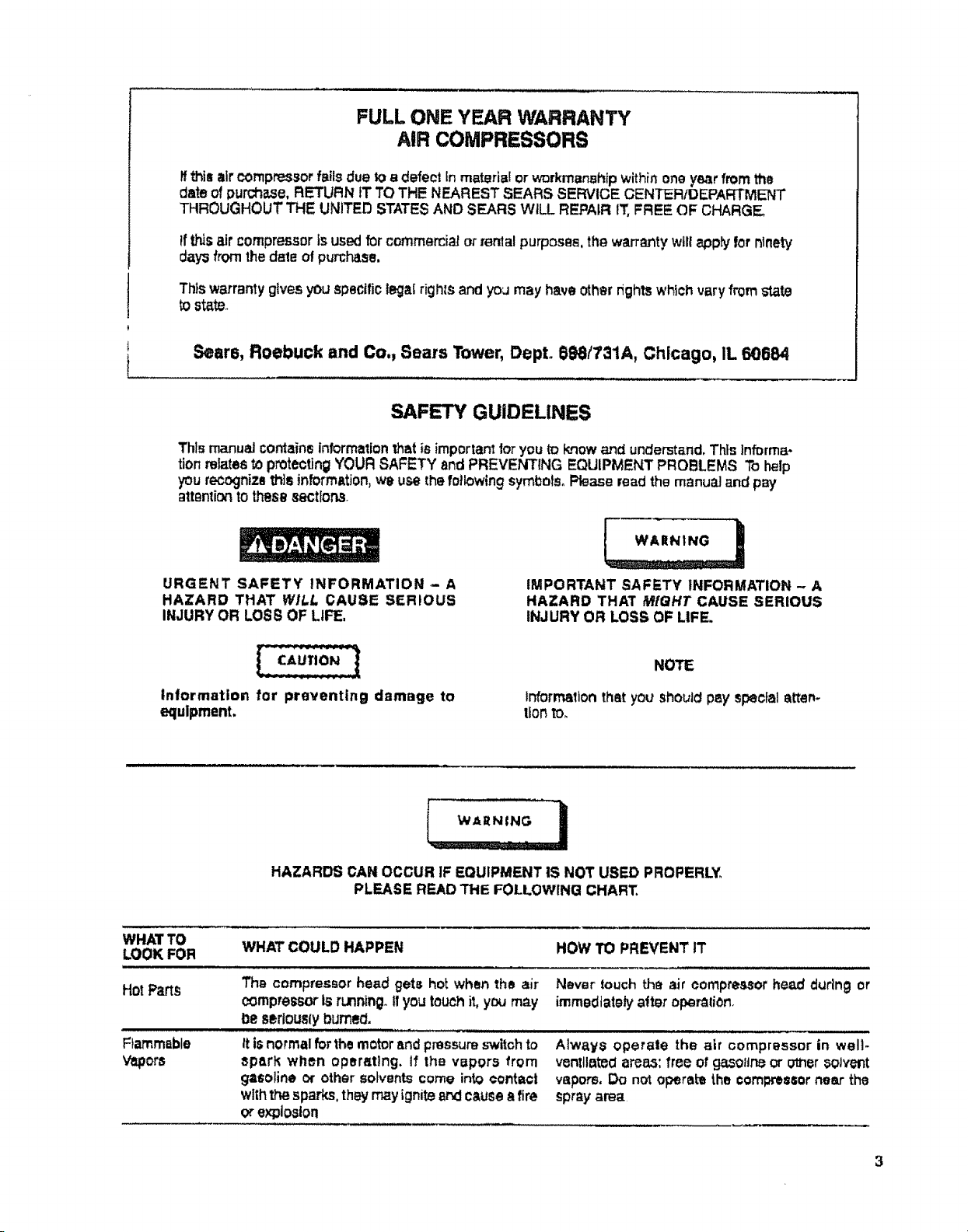
AIR COMPRESSOR DIAGRAM
44 45 46 47
X
42
33 32
t
25
4
12
22
23
18
21
2O
Page 13

KEY
NO.
PARTMUMBER
PARTS LIST
DESCRIPTION
10
11
12
13
14
15
16
17
18
19
20
21
22
?.3
24
26
26
27
28
29
3O
31
32
33
34
35
38
37
3S
S9
4O
41
42
LA-1976
LA-1979
LA.2035
LA4_;7
2
3
4
5
6
7
B
9
LA-IB_'7
LAd779
CAC.33t._
LA-1975
LA-2035
CAC-107;)
5SF-0129-ZN
CAC-1080
LA.1994,1
CAG.I062
CAC-1099
SSF-S05
CA,C-1098
TA-4136
TA-4135
TA.4140
TA-4139
STD541437
CAC,4293
CAC-4313
CAC-60
LA-1610-1
SUDL-B-1
LA-1gT8
CAC-1087
CAC.1086
CAC-334
SSF-t318-ZN
CAC,4290
SSP-7513
CAC-333-1
BSN-8001
SSP.71;21
CAC-1120
CAG-f083
C-GA,344
CAC-1084
SS-20"t2
88.2071
H-Z0S9
CAC-487
SS-3_-CD
CAC.36S
TIA-4-325
TIA-412S
CAC,61
8UDL-403-1
Model No. Label (Model No. 919.154120)
Model No, Label (Model No, 91B,_4020)
Model No. Label (Model No.9t9,_4320)
Model No, Label (Model No.919,154420)
Maintenance Label
Hot Surfsoe Label
9kroud - front
Performan=e Label (Model No, _19.154120& 919.154020)
Performance Label (Model NO,_9.1S4320 & 919.1544:_0)
Not USed
Braolmt (2 ueed - included with _€11)
I,ooknut '/4"-20(2 used)
Tool troy
Advanoad toch. Label
Rear ahrou_ assembJy (include_ 2 ea. #7)
U-Channel isolator
Shoulder screw (2 used)
Isolator (2 used)
Air Tank (Model No. 919.154020)i
Air "lllnkASME (Model No. 919,1r_4120)
Air Tank (Model No. 919.154320)
Air Tank (Mod_l NO.919.154420)
Nut _/o"-16(2 u=ed)
Wheel (2 used) (Model No. 919,11_4020& 919.154120)
Wheel (z u_d) (,ModelN_. e_e.l_20 s _g._4420)
Shoulder bolt ¾ -tB × 21/= (2 ut_.)
Beam Craftsman Label
Rubber foot strip
Dmln Tank Label
Handle (black firdah)
Handlegrip
Control cover
Sorew - onntrol oaver
Check valve
Nut sleeve assembly (for %" O,D_,Tube)
Shroud Plate
RMchet Fastener (2 used)
Nut (Tighten until it SlOpsagainst head)
Silicone Sleeve
Outlet tube
Pmuure Gauge (2 used)
Rear cover
Nipple (%" NPT × 1Vd°tong)
Nipple (_/,"NPT× 1W' tong)
Adapter
Regulator
PIp_ plug T/_,NPT
Mtmlfold
SMIty valve {Model No. 919.1540;Z0& 919.154320)
Safety valve ASME (Model No. 9t9.164120& 919,154420)
Mounting Ring- control cover
Cord assembly- line
13
Page 14

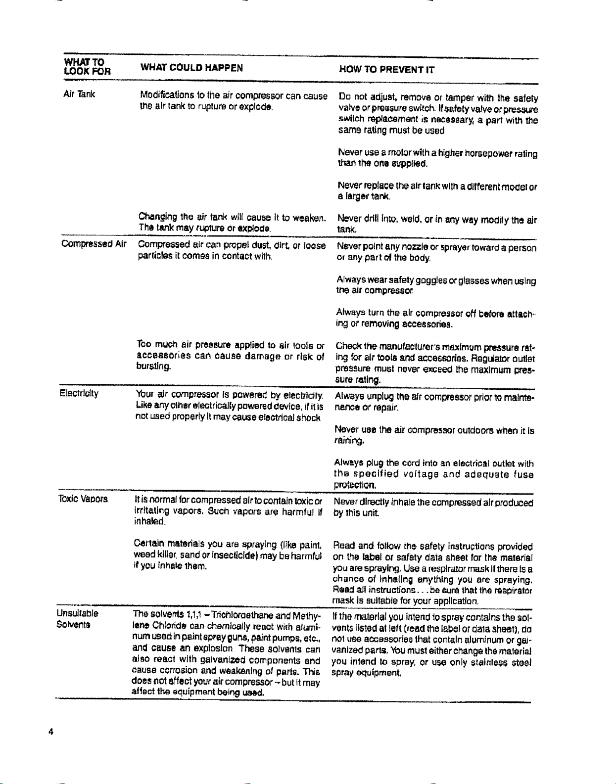
COMPRESSOR PUMP DIAGRAM
56
58
59
60
6t
62
63
ft
___ M_K TOWARDS MOTOR,
__,/64
65
Page 15

KEY
NO. PARTNUMBER
PARTS LIST
DESCRIPTION
43 CAC-4220-1
44 LA.153t-1
45 CAC-1085
46 STDSTS0";r_5
47 STDS75026
48 SSP-9013
49 LAo!535
SO 88P.6088
51 CAC-4215-t
52 5SW-7367
53 KK.4315
64 SSF-961
55 CAC-260-2
S6 CAC-t046
57 SSF-990
S8 CAG-1067
Sg SSF-6640
60 CA(;-1066
61 CAC-4281
62 SSG-8166
_,e3
U'64
65 €-MO-3006
68 CAC-4303
67 SSF.2043
68 CAG-1055
69 SSF-3101
70 88T302S
Pressure switch
On-Otf Labol
Pressure relief tuba (wurmltube before installing on #50,)
Nut (for !/4"O,D, Tube)
Farrulo (fOr ',_"O,D, Tube)
Tube insert
Warning Label
Barbed fitting
Cord assembly- motor
Stz,atn roller (2 used)
Pressure release valve mn_ mounting nut (included with #43)
Screw I/_,0AB x oI4_long (2 zINd)
Air Filter
intake muffler
SCrew 1/4"- 20 × 1t/4- (2 used, torque 7-10 it° lbs.)
Head
Stud V4"-20×11/..'(2 used, _rque 7-10 ft. Ibs°)
Gasket
Y_lVeplate ass4tmbly(inedddU vaJVes,rostrlctore,& screws)
O-ring
Connecting rod assembly (torque screw 30.,35 In. Ibs.)
Cylinder slsmve(position 10_etlng mark townrds motor)
Motor 2 HP
Eccentric/Bearing Assyo(In_ludai I ca, #70)
Screw (eccentric, torque 50.60 in. Ibs.)
Fen
Screw #10-24 × _/." long (torque 30.35 in. Ibs.)
Bearing (eccentric)
H-5796
9-16269
Sl-30-08-4-B
Key S3 & 64 Car, only be
NOT ILLUSTRATED
Air Hose assembly (_/_"l.D._ 15')
Air Chuok
Ownare Manuel
purcJ18_hdampart of KK-4_t e-_onnectlngrod kit
15
Page 16

SL A/RS
OWNERS
MANUAL
SERVICE
MODEL NO.
919.154020
9!9.154120
919.154320
919.154420
HOW TO ORDER
REPAIRPARTS
CRAFTSMAN
PERMANENTS,( LUBRICATED
AIR COMPRESSOR
Now "hat you have purchasedyo)JrSears Air Compressor shoulda
need ever e0dstfor repairpart_oi service sirt_ptycontaot anySears
Service Centerand mast Sears Floebuckand Co stores Be sure
toprovideallpertinentta_ whe_lyou catlor visit
The modet number of your Se=sfAir Compressoris919............. -_ ,
ThisnumberDartbe found on thei|_l:)e]WhiChfs IOOaledOnbe back
Offhe shroud
WHEN ORDERING REPAIR PAR_S ALWAYSGIVE THE
FOLLOWING INFORMATION:
PART NUMBER
IPART DESCRIPTION
$1_lF084 9 10till
, MODEL NUMBER INAME OF ITEM
Allparts listed may beordered fm_nanySears Service Centerand
mosl Sears_tores
Iflhe parts youneed am notstork_dlooa|ly yourorderw/!l be elnc
ironicallytransmittedto a 8eat_ R_paJrParts DistributionCenl_t for
handllng
Sears, Roebuck and Co., _hlcago, IL 60684 U.S.A.
p'tin_di_U.S.A.
 Loading...