

Page 1
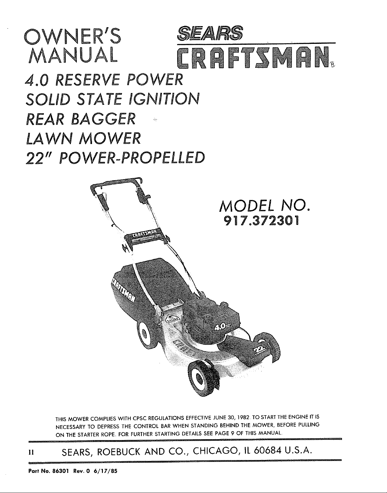
OWNER'S
MANUAL
4.0 RESERVE
SOLID STATE
REAR BAGGER
LAWN M0 WER
22"
POWER-PROPELLED
POWER
IGNITION
[,
MODEL NO.
917.372301
THIS MOWER COMPLIES WITH CPSC REGULATIONS EFFECTIVE JUNE 30, 1982 TO START THE ENGINE IT IS
NECESSARY TO DEPRESS THE CONTROL BAR WHEN STANDING BEHIND THE MOWER, BEFORE PULLING
ON THE STARTER ROPE, FOR FURTHER STARTING DETAILS SEE PAGE 9 OF THIS MANUAL
u SEARS, ROEBUCK AND CO., CHICAGO, IL 60684 U.S.A.
#ll., ..
Part No. 86301 Rev, 0 6/17/85
Page 2
CRAFTSMAN quality LAWN CARE equipment
TWO YEAR LIMITED WARRANTY ON CRAFTSMAN POWER MOWER
Far two years from the date af purchase, when this Craftsman power mower is maintained, lubri-
cated and tuned-up according to the instructions in the owner's manual, Sears will repair, free of
charge, any defect in material and workmanship
If this Craftsman power mower is used for' commercial or rental purposes, this warranty applies far
only 90 days from the date of purchase,
This warranty does not cover:
- Expendable items which become worn during normal use, such as rotary mower blades, blade
adapters, belts, air cleaners and spark plugs
- Repairs necessary because af operator abuse or negligence, including bent crank-shafts and the
failure to maintain the equipment according to the instructions contained in the owner's manual
WARRANTY SERVICE ISAVAILABLE BY RETURNING THE CRAFTSMAN POWER MOWER TO THE NEAR-
EST SERVICE CENTER/DEPARTMENT IN THE UNITED STATES_
This warranty gives you specific legal rights, and you may also have other rights which vary from
state to state_
SEARS, ROEBUCK and CO. Department 698/731A Sears Tower, Chicago, IlL 60684
MAINTENANCE AGREEMENT
A SEARS MAINTENANCE AGREEMENT IS AVAILABLE ON THIS PRODUCT CONTACT YOUR NEAREST
SEARS STORE FOR DETAILS_
CUSTOMER RESPONSIBILITIES
Read and observe the rules for safe use. Always use care when using your lawn mower. Keep away
from moving parts
DO NOT work an your lawn mawer with engine running Always keep your lawn mower clean.
Follow a regular schedule in maintaining, caring for and using your lawn mower, A well cared for
mawer will run and last longer
Follow the instructions under "Maintenance" and "Storage" sections of this Owner's Manual
Blade, blade flange, air cleaner/air filter, spark plug are expendable parts which are your respon-
sibility
TABLE OF CONTENTS
WARRANTY ................................................................................................................................. 2
KNOW YOUR CRAFTSMAN MOWER ............................................................................................ 3
RULES FOR SAFE USE................................................................................................................ 4
HELP YOUR LAWN MOWER LAST LONGER ........................................................................................ 5
HOW TO SET-UP YOUR MOWER ................................................................................................... 6
BEFORE STARTING ENGINE ...................................................................................................... 8
HOW TO USE YOUR MOWER ............................................................................................................ g
MAINTENANCE ............................................................................................................................... 11
STORAGE ........................................................................................................................... 15
REPAIR PARTS........................................................................................................................................ 17
ENGINE REPAIR PARTS............................................................................................................ 24
]"ROUBLE SHOOTING ................................................................................................................................... 27
2
Page 3

KNOW YOUR CRAFTSMAN MOWER
ZONE/ENGINE
CONTROL
HANDLE KNOB
GRASS
CATCHER LATCI"
CONTROL BAR
CONTROL
PLATE
\
CABLE CLIP
ENGINE OIL CAP WITH DIPSTICK
GASOLINE FILLER CAP
WHEEL ADJUSTER
ON EACH WHEEL)
HANI
ENGINE CONTROL KNOB
PRIMER
MEETS CPSC BLADE SAFETY REQUIREMENTS
SPECIFICATIONS TOOLS REQUIRED
Oil: Use SAE 10W30 motor oil SAE 30
motor oil can also be used
Gasoline: Use unleaded automotive gas-
oline, Regular automotive gasoline can also
be used DO NOT use premium gasoline,
or gasoline containing alcohol
AIR FILTER
FIG I
DRIVE COVER
H_O SING
FOR CATCHER ASSEMBLY
3/8 and 7/16" wrench or
adiustable wrencM
Medium flat blade screwdriver.
FOR BLADE REMOVAL
Standard 15/16" box or open
end wrench_
Sears Rotary Walk-Behind Power Mowers conform to the safety standards of the American National Standards In-
stitute, Outdoor Power Equipment Institute, and U_S Consumer Product Safety Commission, as applicable,
3
Page 4
RULES FOR SAFE USE
CAUTION: ALWAYS DISCONNECT SPARK PLUG WIRE AND PLACE WIRE WHERE
I1 CANNOT CONTACT SPARK PLUG TO PREVENT ACCIDENTAL STARTING
WHEN SETTING--UP, TRANSPORTING, ADJUSTING OR MAKING REPAIRS TO
YOUR MOWER.
IMPORTANT
FEDERAL REGULATIONS REQUIRE THE ENGINE CONTROL INSTALLED ON THIS MOWER IN ORDER TO
MINIMIZE THE RISK OF BLADE CONTACT INJURY DO NOT UNDER ANY CIRCUMSTANCE ATTEMPTTO
DEFEAT THE FUNCTION OF THE OPERATOR CONTROL
1 Please read your owner's manual,
Only allow persons who know the
safety rules to use your mower
2 DO NOT tie the control bar to the
handle Control must be free to
permit brake engagement when
handles and control are released,
3 DO NOT allow children to use your
mower
4_ Check your' mower over before each
time you mow Tighten any loose
bolts, nuts, etc_
5. Remove all sticks, stones, wires,
cans, boards, etc. from area to be
mowed. These objects can be
thrown by the blade.
6 DO NOT allow children, bystanders,
or pets in the mowing area_
7 BE CAREFUL- WHEN THE ENGINE IS
RUNNING THE BLADE IS TURNING_
8 Always shut off engine before try_
ing to adjust wheel heights
9 When engine is running, DO NOT
put hands or feet under mower' or in
the discharge chute, nor make any
adjustments_
10_ Stay clear of discharge opening
at all times,
11_ Check gasoline before each use_
Do not fill gas tank when engine
is running, when indoors or when
engine is hal Allow engine to cool
before filling gas tank_ Wipe off
any spilled gasoline before start-
ing engine
12_ Mow only in good light_
13 Wear only solid shoes when mow-
ing, DO NOT operate mower when
barefoot, or wearing open sandals
14_ Disengage drive control on power
propelled mower's before starting
engine_
15 DO NOT use a damaged mower'.
Always have damage repaired
before mowing
16 Always stop engine when not cut-
ting grass or when crossing gravel
drive, sidewalk, or roadway.
17_ Never pull mower towards you, al-
ways follow mower to cut grass_
18. Never use your mower without pro-
per guards or deflectors in place.
19. Always mow across a slope or in-
clined area. DO NOT mow up or
down a slope or inclined area,
20. DO NOT mow in wet grass_ DO NOT
run with the mower
21. DO NOT run your' mower indoors.
Exhaust gasses are deadly poison
22_ DRAIN THE GASOLINE tank before
transporting your mower inside
your car or other vehicle.
23 DO NOT run your mower if it vi-
brates too much Stop engine and
make repairs. Vibration is an indi-
cation of damage.
24. DO NOT change the engine gow
ernor settings to over-speed the
engine-Ldamage or' injury can re-
sult_
25 If a grass catcher is used on your
mower, check the catcher often for
damage_ Use only recommended
catcher_ Always stop engine to re-
move grass catcher_
26_ DO NOT store your mower or gas-
aline where fumes may reach an
open flame and cause a fire.
27_ Always wear safety glasses or eye
shields before starting your lawn
mower and while mowing
4
Page 5

The operation of any lawn mower can result inforeign objects thrown into the eyes,
which can result in severe eye damage Always wear safety glasses or eye shields
before starting your lawn mower and while mowing, We recommend Wide Vision
Safety Mask for over the spectacles or standard safety glasses, available at Sears
Retail or Catalog Stores_
ACCESSORIES TO HELP YOU GET THE MOST FROM YOUR MOWER
CLIPPING DEFLECTOR: Converts rear bagging mowers to side discharge to disperse clippings safely and
evenly_
HIGH WHEEL KIT: A pair of 12_inch rear wheels improves handling on soft, spongy lawns and uneven
terrain_ Includes height adjusters; doesn't affect cutting height range,
MOWER COVER: Sears Tyvek®cover protects mower from weather when stored outdoors_
GAS CAN: A new gas can keeps rust and dirt out of fuel system for longer engine life and improved per_
formance_ Craftsman gas cans have built in filters to keep impurities out of your engine
THESE ACCESSORIES WERE AVAILABLE AT MOST SEARS STORES AND THROUGH THE CATALOG AT THE
TIME THIS MANUAL WAS PRINTED.
IMPORTANT TIPS TO HELP YOUR LAWN MOWER START FASTER, RUN AND PERFORM BETTER
1_ USE UNLEADED GASOLINE: It burns cleaner and leaves less residue inthe engine. Regular gasoline can
also be used. DO NOT use gasoline containing any alcohol or with any additives.
2_ DRAIN OR RUN-OUT ALL GASOLINE FROM TANK AT THE END OF THE SEASON: DO NOT leave gaso-
line in your mower when stored for long periods It will "GUM" your engine. Run engine until the gaso-
line runs out.
3. START EACH MOWING SEASON WITH FRESH GASOLINE: DO NOT keep gasoline in your can. If your
gasoline can is starting to rust, replace can.
4 CHANGE YOUR SPARK PLUG EVERY SPRING: An old, corroded spark plug prevents fast starting and
smooth running engine.
5. REPLACE YOUR AIR CLEANER OR FILTER OFTEN: Dirt, along with heat can harm your engine, the
cleaner or filter will clog up, preventing clean air from reaching your engine. See "Air Cleaner/Filter"
section of this manual for replacing air cleaner or filter.
6. USE SAE 10W30 OIL: DO NOT use SAE 10W40 oik
7. CHANGE OIL AS RECOMMENDED: IMPORTANT - chan_j_ oil after the first two (2) hours of use, then
every 25 hours of use,
8, REPLACE THE BLADEWHEN NEEDED: You can sharpen the blade, but we do not recommend it. Erosion
from hitting foreign objects can damage the blade Replace blade with one specifically designed
for your mower.
9. AT THE END OF THE SEASON, CLEAN YOUR MOWER: IMPORTANT- first disconnect the spark plug wire,
If possible, store your mower in a well ventilated area and protected from moisture_
10. FOLLOW THE MAINTENANCE SUGGESTIONS IN YOUR OWNERS MANUAL: Read your manual and
keep it in a convenient place for easy reference°
11. DO NOT PUT ANY ADDITIVES IN THE OIL OR GASOLINE: DO NOT USE GASOHOL, or gasoline contain-
ing any alcohol
s
Page 6
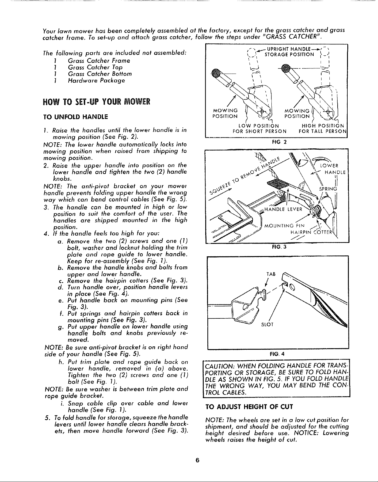
Your lawn mower has been completely assembled at the factory, except for the grass catcher and grass
catcher ftame, To set-up and attach grass catcher, follow the steps under "GRASS CATCHER".
The following parts are included not assembled:
1 Grass Catcher Frame
1 Grass Catcher Top
1 Grass Catcher Bottom
1 Hardware Package
HOW TO SET-UPYOURMOWER
TO UNFOLD HANDLE
I_ Raise the handles until the lower handle is in
mowing position (See Fig° 2)_
NOTE: The lower handle automatically locks into
mowing position when raised from shipping to
mowing positiom
2. Raise the upper handle into position on the
lower handle and tighten the two (2) handle
knobs_
NOTE: The anti-pivot bracket on your mower
handle prevents folding upper handle the wrong
way which can bend control cables (See Fig_ 5)_
3_ The handle can be mounted in high or low
position to suit the comfort of the uset_ The
handles are shipped mounted in the high
position.
4. If the handle feels too high for you:
a_ Remove the two (2) screws and one (I)
bolt, washer and Iocknut holding the trim
plate and rope guide to lower handle.
Keep for re-assembly (See Fig. 1)_
b. Remove the handle knobs and bolts from
upper and lower' handle.
c. Remove the hairpin cotters (See Fig. 3).
d_ Turn handle over, position handle levers
in place (See Fig. 4).
e_ Put handle back on mounting pins (See
MOWING
POSITION
LOW POSITION
FOR SHORT PERSON
llll,
MOUNTING PIN
MOWING
POSITION
HIGH POSITION
FOR TALL PERSON
FIG 2
LOWER
HANDLE
SPRFNG
HAIRPIN COTTER
///
FIG,3
Fig.3).
fo Put springs and hairpin cotters back in
mounting pins (See Fig. 3)_
g. Put upper handle on lower handle using
handle bolts and knobs previously re-
moved.
NOTE: Be sure anti-pivot bracket is on right hand
side of your handle (See Fig. 5)_
h. Put trim plate and rope guide back on
lower handle, removed in (a) above_
Tighten the two (2) screws and one (1)
bolt (See Fig_ l)o
NOTE: Be sure washer is between trim plate and
rope guide bracket.
i, Snap cable clip over cable and lower
handle (See Fig_ 1).
5. To fold handle for storage, squeeze the handle
levers until lower handle cleats handle brack-
ets, then move handle forward (See Fig. 3).
CAUTION: WHEN FOLDING HANDLE FOR TRAN_-
PORTING OR STORAGE, BE SURE TO FOLD HAN-I
DLE AS SHOWN IN FIG. 5. IF YOU FOLD HANDLEI
THE WRONG WAY, YOU MAY BEND THE CON- I
TROL CABLES. J
TO ADJUST HEIGHT OF CUT
NOTE: The wheels are set in a low cut position for
shipment, and should be adjusted for the cutting
height desired before use. NOTICE: Lowering
wheels raises the height of cut.
FIG 4
6
Page 7
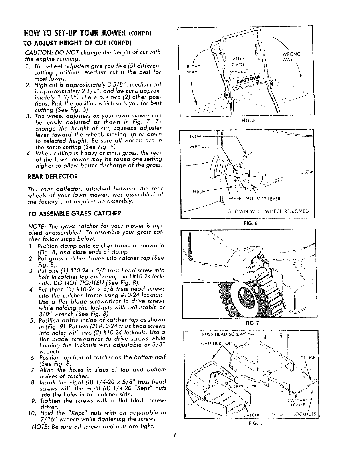
HOW TO SET-UPYOURMOWER(CONT'D)
TO ADJUST HEIGHT OF CUT (CONT'D)
CAUTION: DO NOT change the height of cut with
the engine running°
1_ The wheel adjusters give you five (5) different
cutting positions, Medium cut is the best for
most lawns.
2, High cut is approximately 3 5/8", medium cut
is approximately 2 1/2", and low cut is approx-
imately 1 3/8"o There are two (2) other post.
tions_ Pick the position which suits you for best
cutting (See Fig. 6),
3. The wheel adjusters on your lawn mower can
be easily adjusted as shawn in Fig, 7_ To
change the height of cut, squeeze adjuster
lever toward the wheel, moving up or do_ n
to selected height. Be sure all wheels are in
the same setting (See Fig, _)
4, When cutting in heavy or mni_l grass, the re_
of the lawn mower may be raised one setting
higher to allow better discharge of the grass.
REAR DEFLECTOR
The rear deflector, attached between the rear
wheels of your lawn mower, was assembled at
the factory and requires no assembly.
TO ASSEMBLE GRASS CATCHER
NOTE: The grass catcher for your mower is sup_
plied unassembled. To assemble your grass cat-
cher follow steps below,
1. Position clamp onto catcher frame as shown in
(Fig, 8) and close ends of clamp°
2_ Put grass catcher frame into catcher top (See
Fig. 8).
3, Put one (1) #10-24 x 5/8 truss head screw into
hole in catcher top and clamp and #10-24 lock-
nuts, DO NOT TIGHTEN (See Fig_ 8).
4, Put three (3) #10-24 x 5/8 truss head screws
into the catcher frame using #10.24 Iocknuts_
Use a flat blade screwdriver to drive screws
while holding the Iocknuts with adjustable or
3/8" wrench (See Figr 8).
5. Position baffle inside of catcher top as shown
in (Fig. 9). Put two (2) #10-24 truss head screws
into holes with two (2) #10-24 Iocknuts. Use a
flat blade screwdriver to drive screws while
holding the Iocknuts with adjustable or 3/8"
wrench.
6. Position top half of catcher on the bottom half
(See Fig, 8)°
7, Align the holes in sides of top and bottom
halves of catcher,
8. Install the eight (8) 1/4-20 x 5/8" truss head
screws with the eight (8) 1/4-20 "Keps" nuts
into the holes in the catcher side.
9_ Tighten the screws with a flat blade screw-
driver.
10_ Hold,the "Keps" nuts wdh" an adjustable or
7/16 wrench while tightening the screws.
NOTE: Be sure all screws and nuts are tight.
RIGHT
WAY
FIG, 5
_jl WHEEL ADJUS1E2 LEVER
SHOWN WITH WHEEL REMOVED
FIG. 6
FIG 7
TRUSS HEAD bCREW_ _ "
CATCHER TOP
FIG fl
Page 8
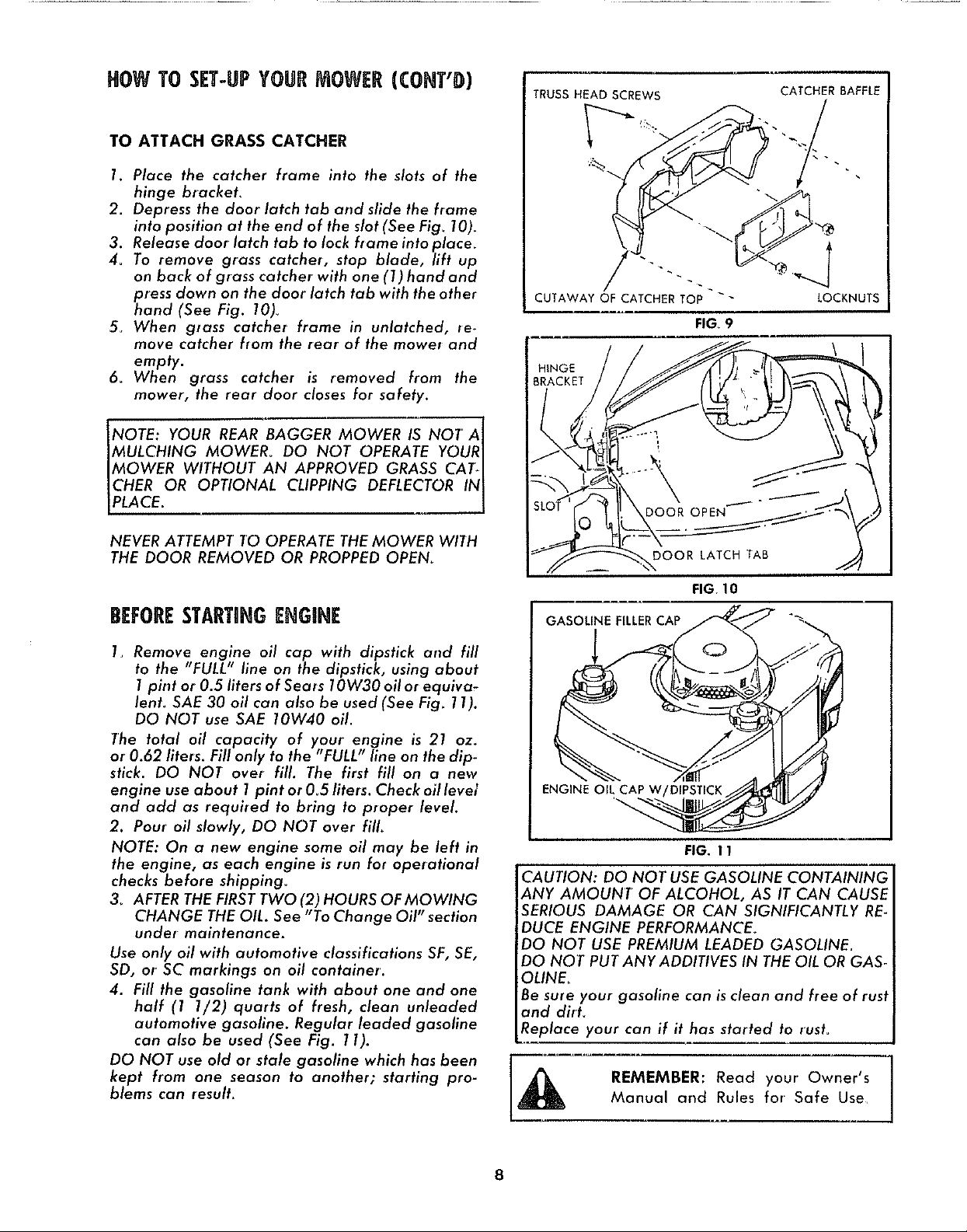
HOW TO SET-UPYOURMOWER (CONT'D)
TO ATTACH GRASS CATCHER
1. Place the catcher frame into the slots of the
hinge bracket,
2. Depress the door latch tab and slide the frame
into position at the end of the slot (See Fig_ 10).
3. Release door latch tab to lock flame into place_
4, To remove grass catcher, stop blade, lift up
on back of glass catcher with one (1) hand and
press down on the door latch tab with the other
hand (See Fig. 10)_
5o When grass catcher frame in unlatched, ie-
move catcher from the rear of the mowel and
empty.
6. When grass catcher is removed from the
mower, the rear door closes for safety.
NOTE: YOUR REAR BAGGER MOWER IS NOT' AI
MULCHING MOWER_ DO NOT OPERATE YOURI
IMOWER WITHOUT AN APPROVED GRASS CAT/
ICHER OR OPTIONAL CLIPPING DEFLECTOR INJ
IPLACE. J
TRUSS HEAD SCREWS CATCHER BAFFLE
CUTAWAY OF CATCHER TOP " LOCKNUTS
FIG 9
HINGE
BRACKET
1
NEVER ATTEMPT' TO OPERATE THE MOWER WITH
THE DOOR REMOVED OR PROPPED OPEN°
BEFORESTARTaNGENGINE
1_ Remove engine oil cap with dipstick arrd fill
to the "FULL" line on the dipstick, using about
1 pint or 0.5 liters of Sears 10W30 oil or equiva-
lenh SAE 30 oil can also be used (See Fig_ 11).
DO NOT use SAE 10W40 oil.
The total oil capacity of your engine is 21 oz.
or 0.62 liters. Fill only to the "FULL/' line on the dip-
stick. DO NOT over fill. The first fill on a new
engine use about 1 pint or 0°5 liters. Check oil levet
and add as required to bring to proper level.
2. Pour oil slowly, DO NOT over fill.
NOTE: On a new engine some oil may be left in
the engine, as each engine is run for operational
checks before shipping_
3_ AFTER THE FIRST TWO (2) HOURS OF MOWING
CHANGE THE OIL. See "To Change Oil" section
under maintenance.
Use only oil with automotive classifications SF, SE,
SD, or' SC markings on oil container.
4. Fill the gasoline tank with about one and one
half (1 1/2) quarts of fresh, clean unleaded
automotive gasoline. Regular leaded gasoline
can also be used (See Fig. 11).
DO NOT use old or stale gasoline which has been
kept from one season to another; starting pro-
blems can result_
DOOR LATCH TAB
FIG. 10
GASOLINE FILLER CAP
ENGINE OIL CAP W/DIPSTICK
FIG. 1 1
CAUTION: DO NOT USE GASOLINE CONTAINING
ANY AMOUNT OF ALCOHOL, AS IT CAN CAUSE
SERIOUS DAMAGE OR CAN SIGNIFICANTLY RE_
DUCE ENGINE PERFORMANCE,
DO NOT USE PREMIUM LEADED GASOLINEu
DO NOT PUT ANY ADDITIVES IN THEOIL OR GAS-
OLINE_
Be sure your gasoline can is clean and free of rust
and dirt°
Replace your can if it has started to rust_
REMEMBER: Read your Owner's
Manual and Rules for Safe Use
8
Page 9

HOW TO USEYOUR MOWER
[IMPo.TA.TI
ENGINE CONTROL
CAUTION: THE BLADE TURNS WHEN THE ENGINE
IS RUNNfNG_
YOUR MOWER IS EQUIPPED WITH AN OPER-
ATOR ZONE ENGINE CONTROL WHICH REQUIRES
THE OPERATOR TO BE POSITIONED BEHIND THE
MOWER HANDLE TO START AND OPERATE THE
MOWER.
THE CONTROL BAR MUST BE DEPRESSED TO THE
HANDLE TO START AND RUN THE ENGINE, RE-
LEASING THE CONTROL BAR WILL STOP THE
ENGINE, AN INTERNAL ENGINE BRAKE ASSISTS
THE BLADE IN STOPPING QUICKLY.
WHEN THE OPERATOR LEAVES THE NORMAL
MOWING POSITION TO REMOVE THE GRASS
CATCHER, CHANGE THE CUTTING HEIGHT, PICK
UP STICKS OR OTHER OBJECTS IN THE MOWING
PATH, THE ENGINE WILL AUTOMATICALLY STOP
WHEN THE CONTROL BAR IS RELEASED,
CAUTION: FEDERAL REGULATIONS REQUIRE THE
ENGINE CONTROL INSTALLED ON THIS MOWER
IN ORDER TO MINIMIZE THE RISK OF BLADE CON-
TACT INJURY. DO NOT UNDER ANY CIRCUM-
STANCE ATTEMPT TO DEFEAT THE FUNCTION
OF THE OPERATOR CONTROL
!NGINE CONTROL KNOB •: ....... _L_
_ = "1 GASOLINE FILLER CAP
PRIMER
FIG 12
C%E ENGINE
CONTROL
1O ENGAGE DRIVE CONT Ol
Ergo :_E
CONTROL
R
l
FIG 13
ENGINE CONTROL
The engine speed is controlled by a lever (red
knob) located on right side of englne_ It has
"HIGH" and "LOW" positions "HIGH" position is
for starting engine, heavy cutting and better
grass bagging. "LOW" position is for light cut-
ting, trimming and fuel economy (See Fig° 12),
TO START ENGINE
THE CONTROL BAR MUST BE DEPRESSED TO THE
HANDLE TO START AND RUN THE ENGINE_
NOTE: The carburetor has a fixed fuel mixture
and has a primer to assist starting
1, Check oil level; check gasoline tank for gaso-
line; and make sure spark plug wire is attach,
ed.
2. Push lever forward to "HIGH" position (See
Fig. 12).
3. When starting a cold engine, push the primer
five (5) times before pulling starter rope_ Use
firm pushes when pushing primer, wait several
seconds between each push (See Fig, 12)o
4, Repeat step 3 above as required_
CONTROL
RELEASED
ENGINE STOP
ENGINE
CONTROL
DEPRESSED
START, RUN
FIG 14
FIG,15
g
Page 10

HOW1'0 USEYOURMOWER(CONT'O)
TO START ENGINE (CONT'D)
NOTE: In cooler weather the need to repeat prim_
ing procedures may be necessary, when weather
is warmer over priming may result in flooding.
If you do flood engine wait a few minutes before
repeating priming procedures_
It is not normally necessary to use the primer to
start warm engine°
5. Position yourself as shown in Fig_ 15_
6. Pull on starter handle quickly°
7_ DO NOT allow starter rope to snap back°
8. To stop the engine, release the control bar
(See Fig. 14).
IF ENGINE DOES NOT START
1. Check blade - remove spark plug wire when
checking blade. If blade is loose, see "BLADE
AND BLADE FLANGE CARE" of manual for in*
structions on tightening blade.
2. Check air filter - replace if clogged_ See "Air
Filter" section.
3_ Check spark plug - if dirty, clean or replace_
4_ Observe that lower end of the engine control
cable is actuating the lever mounted on the
engineL
5. Engine may be flooded - wait a few minutes
and repeat starting procedure.
NOTE: If then your engine will not start, contact
your nearest Sears Service Department for' help.
ZONE/ENGINE CONTROL
SCREWS
FIG_ 16
JAM NUT "D" JAM NUT"C"
FIG 17
BLOCK OF WOOD
Your mower is equipped with a zone/engine con-
trol attached arrd requires no adjustments (See
Fig_ 13).
DRIVE CONTROL
The power-propelling forward motion is con-
trolled by pulling the control bar down to handle
and pushing control forward to engage position
(See Fig. 13).
Forward motion will stop when the control bar
is released.
To stop forward motion without stopping the
engine, release the control bar slightly until the
drive control disengages. Depress control bar to
handle to continue mowing without self-propel-
ling.
To turn corners, you may prefer to keep the drive
control engaged, and push down on the handle,
lifting the front wheels off the ground and turin
ing mower'.
POWER-PROPELLED DRIVE
1. Your power-propelled drive is accomplished
by a belt drive from the engine crankshaft to
a worm gear case.
2_ The drive belt isspring-loaded at the gear case
to maintain proper belt tension. Keep the area
FIG_ 18
FIG 19
lo
Page 11

POWER-PROPELLED(CONT'D)
around the gear case clear of trash by re-
moving drive cover and cleaning (See Fig.
76 and 17)_
3. The gear case is lubricated with multi-purpose
automotive grease° DO NOT USE ANY OTHER
type grease or oil in the gear case. See "GEAR
CASE" under "MAINTENANCE".
4. Check your mower, each time you mow, to be
sure that the front wheels turn freely_ If wheels
DO NOT turn freely, remove any trash which
may have gotten into the wheel, pinion, or
bearing areas.
5. If at any time, the drive belt is replaced, use
only factory specified belt to get longer life
and maximum performance.
MOWING TIPS
1. Under certain conditions it may be necessary
to raise the height of cut from overloading
the engine and leaving clumps of grass clip-
pings.
2_ For extremely heavy cutting, make the width
of your cut 1/2 to 3/4 the normal cut. This will
reduce the load on the engine and give you
cleaner cutting and bagging.
3. The user should note that when cutting moist,
heavy grass with a rear bagging mower,
clumps of cut grass may fail to enter the grass
catcher. To pick up the clumps if they occur,
run the mower over the area a second time.
4. Under certain conditions a trail of grass clip-
pings may be left at the right side of the
mower. Mowing in a clockwise direction with
a small overlap will allow these clippings to be
collected on the next pass.
MAINTENANCE
REAR DEFLECTOR
FIG. 20
FIG 21
Be good to your mower. Once a year put on a
new mower blade, a new spark plug, and a new
air filter. A new blade cuts better. With a new
spark plug your engine will start and run better.
A new air filter assures proper air-fuel mixture.
It will help your engine run better and last longer.
MOWER:
BLADE/BLADE FLANGE CARE
CAUTION: Protect your hands when removing or]
installing blade of your mower. Wear heavyJ
gloves and/or wrap blade with heavy cloth when I
holding blade. Always use a block of wood whenJ
tightening blade nut or blade bolt, J
Use only a Sears authorized replacement blade
to get the best cutting results°
CAUTION: Disconnect spark plug wire from spark
plug and place wire where it cannot come in con.
tact with the spark plug.
OIL HERE
REAR DOOR
FIG, 22
1. To remove the blade and blade flange, turn
mower on its side with carburetor and air
filter up (See Fig. 18)_
2. Take blade nut off by turning counter-clock-
wise. Use a 15/16" box or open end wrench on
the blade nut (See Fig. 18)o
3. Put a block of wood between the blade and
mower housing toprevent blade rotation when
removing and tightening blade nut.
NOTE: Always check the blade flange when
changing the blade to be sure tab has not been
damaged (See Fig. 19).
4. If the tab in the blade flange is damaged
replace the blade flange.
11
Page 12

MAINTENANCE(CONT'D)
BLADE/BLADE FLANGE CARE (CONT'D)
NOTE: The blade flange with tab attaches the
blade to crankshaft, It is not intended to protect
the crankshaft. The tab must be in good condition
and located in slot of crankshaft to keep blade
attached.
5_ Put the blade flange on the engine crankshaft
with the tab in the slot of the crankshaft (See
Fig, 19).
6_ Put the blade on the crankshaft as shown in
(Fig_ 19)_ Be sure the word "TOP" (stamped
in the blade) is toward the engine.
7_ Install the flat washer, two (2) formed washers
and blade nut as removed above,
NOTE: We recommend that the blade nut be re-
placed when installing a new blade_
8_ Tighten blade nut. The recommended tighten-
ing torque is 50-65 ft_ Ibs. Use block of wood
to prevent blade rotatiom
NOTE: Torque wrenches are available at most
Sears retail stores and through the catalog.
A loose blade can result in difficult starting of
engine,
We do not recommend sharpening blade-but if
you do, be sure blade is balanced_ An unbalanced
blade can cause excessive vibration and contri-
bute to shortening the life of the engine and
mower.
REAR DEFLECTOR
The rear deflector which is attached to the rear of
your' mower is to keep objects from being thrown
out the back of the mower. If your rear deflector
becomes damaged you should replace it (See
Fig_ 20)_
TO ADJUST DRIVE CONTROL CABLE
NOTE: THE DRIVE CONTROL CABLE SHOULD BE
CHECKED OFTEN TO BE SURE THAT GEAR CASE
SHIFTER IS FULLY ENGAGED OR WHENEVER
SERVICE HAS BEEN PERFORMED ON THE GEAR
CASE OR DRIVE CONTROL COMPONENTS.
1. TOadjust, remove the drive cover by removing
two (2) screws. Keep for re-use (See Fig. 16)_
2_ Loosen screw holding cable clamp (See Fig_
17)_
3_ Loosen screws holding cable clamp "A" & "B"
(See Figs. 17 and 27).
4_ Loosen both jam nuts "C" & "D" at the cable
clamp on the gear case adjusting bracket
(See Fig_ 17)_
5. Unhook clutch spring from shifter arm (See
Fig_ 17)_
6_ Hold, clip or tape down the drive control bar
and engage the drive corrtrol (See Fig. 13)_
7_ Move the shifter arm to drive position. To be
sure the jaw clutch is fully engaged, rotate the
front wheels.
HAIRPIN
COTTER
OIL HERE
EACH SiDE
ROL
RACKET
HUBCAP
OIL HERE _.-
ZONE_
CONTROL ¢
LEVER
WHEEL
FIG_23
_" ZONE
FIG 24
8. Hold shifter arm in fully engaged position by
pliers as shown in Fig_ 17. DO NOT pull on
control cable.
9. Tighten jam nut " C" up to bracket until cable is
snug.
10. Tighten cable clamp screw "B" (See Figs. 17
and 21)_
11. Tighten jam nut "D" up to bracket (See
Fig. 77).
12. Tighten screw "A'.
13. Put clutch spring back in place on shifter' arm,
removed in step 5 above.
14. With drive control in engaged position, push
mower back and forth to be sure gear case is
fully engaged.
NOTE: Be sure to disengage drive control before
starting engine.
15_ Put drive cover back in place, removed in step
1 above_
GEAR CASE
1, THE GEAR CASE AND AREA AROUND ALL THE
DRIVE SHOULD BE KEPT CLEAN AND FREE OF
TRASH BUILD-UP.
2, To check gear case area:
a, Remove the drive cover by removing the
two (2) screws (See Fig. 16). Keep for re-
use_
b. Clean trash from around gear case.
c. Put drive cover back, removed in (a)
above,
12
Page 13

MAINTENANCE(CONT'D)
GEAR CASE (CONT'D)
NOTE: The gear case is filled to proper level at the
factory° The only time the lubricant needs atten-
tion, is if service has been performed on the gear
Case.
The gear case must be filled with grease after gear
case has been serviced. Use only multi-purpose
automotive grease. Do not substitute.
LUBRICATION
-- ,,j,
PRESS
L-_
MOWER WHEELS: Lubricating wheels and/or
wheel bearings is not necessary under normal
conditions_
Should conditions require lubrication, thoroughly
clean wheels and/or wheel bearings and axles
and apply a light coating of dry lubricant such as
white graphite. White graphite is available at
Sears retail stores and through the catalog,
REAR DOOR HINGE: Put a few drops of the same
oil as used in the engine on hinge points of rear
door once or twice each year (See Fig, 22)°
GEAR CASE: The gear case is filled at the factory
and does not require any addition of lubricant,
unless the gear case is opened and service
performed. Use only a multi-purpose automotive
grease for refilling after service has been per-
formed° Approximately 2 1/2 oz. required°
FRONT WHEEL ADJUSTERS: Put a few drops of the
same oil as used in the engine on the front wheel
adjusters once or twice each year (See Fig° 23).
GRASS CATCHER
Check your grass catcher often_ Through normal
use it will wear° If catcher needs replacing, re-
place only with a manufacturer approved replace-
ment catcher from Sears. Give the mower model
number when ordering,
NOTE: The catcher may be hosed with water, but
must be dry when used,
FIG 25
APPROX 1/32
HEX HEAD SCREW
CONTAINER
/
ZONE/CONTROL LEVER
Put one or two drops of the same oil as used in
the engine between the zone control lever and
bracket located on left rear of engine (See Fig_
24). Do this once or twice each year_
ZONE/ENGINE CONTROL
Check your zone/engine control cable often for
defects or wear and replace if found to be dam-
aged or worn,
CLEANING
CAUTION: Disconnect spark plug wire from spark
plug and place wire where it cannot come in con-
tact with the spark plug.
1. Turn mower on its side with carburetor up,
FIG 27
2_ Clean the underside of your mower by scrap-
ing to remove build,up of grass and trash,
NOTE: We recommend that you clean the under-
side of your mower after each use.
3. Clean your mower and engine often to keep
build-up of trash from accumulating around
engine, a clogged engine runs hotter and
shortens engine life.
NOTE: We DO NOT recommend using a garden
hose to clean mower unless the electrical system,
muffler, air filter, and carburetor are covered to
keep water out_ Water in engine can result in
shortening engine life_
13
Page 14

MAgNTENANCE(C0NT'D)
GEAR CASE AND DRIVE WHEELS
NOTE: The gear case and drive wheels should be
cared for much llke you would an automobile_
I. On a regular schedule remove the drive cover
and remove any trash around gear case and
belt area.
2. To remove drive cover, remove the two (2)
screws (See Fig. 16). Keep for re-useo
3. Keep your mower clean and properly lubri-
cated_
DRIVE WHEELS
NOTE: Check front drive wheels each time before
you mow, to be sure they move freely.
1. The wheels not turning freely, indicates trash,
grass, cuttings, etc_ are in the drive wheel
area, and must be cleaned to free drive
wheels_
2. If necessary to clean the drive wheels (See Fig.
23) check both front wheels_
a_ Remove hub caps, hairpin cotters and
washers_ Keep for re-USeo
b. Remove wheel from wheel adjusters.
c. Remove any trash, grass cuttings from
inside the dust cover, pinion and/or drive
wheel gear teeth_
d. Put wheels back in reverse of removal
3. If after cleaning drive wheel area, the drive
wheels DO NOT rotate freely, the gear case
needs care_
NOTE: If your gear case requires service we
suggest that you contact Sears Service Center_
_CLOCKWISE
TOREMOVE
AIR FILTER
J
AIR FILTERCOVER
FIG. 28
FIG. 29
ENGINE:
LUBRICATION
TO CHECK AND/TO REPLACE BELT
1. Remove the drive cover by removing the two (2)
screws (See Fig. 16).
2. Inspect belt for wear or damage. If you decide
to replace:
a. Push down on gear case pulley until belt
can be removed from gear case pulley
(See Fig. 25).
3. Turn mower on its side with carburetor upo
4. Loosen hex head screw holding belt snubber in
place and move belt snubber away from pulley
(See Fig. 26).
5. Move belt snubber away from pulley to allow
belt removal.
6. Remove belt from engine pulley on crankshaft,
and carefully slip the belt off over the blade_
CAUTION: The sharp edges of blade can cut the
belt. Use care in installing new belt over blade.
7. To install new belt, reverse procedure as above
in removal.
8_ Move belt snubber back in place, approxi-
mately 1/32" away from belt and tighten hex
head screw (See Fig. 26).
NOTE: Always use only factory approved belt to
assure proper fit and longer' life.
ENGINE: Use of proper oil in your engine and
keeping to full level is essential. Changing oil reg-
ularly will lengthen the life of your engine°
The total oil capacity of your' engine is 21 oz. or
0.62 liters. Fill only to the "FULL" line on the
dipstick° DO NOT over fill. The first fill on a new
engine use about 1 pint or 0.5 liters. Check oil
level and add as required to bring to proper level.
NOTE: On a new engine some oil may be left in
the engine, as each engine is run for operational
checks before shipping.
Use Sears SAE 10W30 oil or equivalent. SAE 30
oil can also be used. DO NOT use SAE 10W40 oil.
Use only oil with automotive classifications SF, SE,
SD, or SC markings on oil container.
Using Sears SAE 10W30 oil will assist engine start-
ing in cool weather'.
Running your engine with oil below safe level or'
with dirty contaminated oil can contribute to short-
ening the life of your engine,
After the first two (2) hours of mowing change the
oil, then change the oil every 25 hours of mowing
thereafter. If you mow under very dusty, dirty
conditions you may need to change the oil more
often.
14
Page 15

MABNTENANCE(tOrn'D)
TO CHANGE OIL
Replace your gasoline can, if your old can starts to
rust. DO NOT use rusty gasoline can, rust and/or
dirt in your gasoline can cause problems,
CAUTION: Disconnect spark plug wire from spark
plug and place wire where it cannot come in con-
tact with the spark plug,
1_ Remove engine oil cap with dipstick, lay aside
on a clean surface, Warm oil drains better°
2_ Tip mower on its side as shown in Fig. 27 and
drain oll into suitable container° Rock mower
back and forth to remove any oil trapped
inside of engine.
3, Wipe off any spilled oil on mower and/or
inside of engine.
4. Fill engine with oil, fill only to the "FULL" line
on the dipstick. DO NOT over fill.
5. Reconnect spark plug wire to spark plug.
AIR FILTER
CAUTION: DO NOT run your engine without air
filter in place.
1_ Your engine will not run properly with a clog-
ged, dirty air filter.
NOTE: DO NOT wash this type air filler_
2_ Replace your air Filter each year, more often if
you mow in very dusty, dirty conditions.
Replacement air filter no. 713332 is available at
most Sears retail stores and through the catalog.
TO CHANGE AIR FILTER
1. Remove the air Filter cover by turning counter-
clockwise to the stop, and pull away from
collar (See Fig. 28),
2. Remove Filter from inside of cover(See Fig_28),
3_ Clean the inside of the cover and the collar to
remove any dirt accumulation.
4. Insert new filter into cover,
5_ Put air Filter cover and Filter into collar a-
ligning the tab with the slot,
6. Push in on cover and turn clockwise to tight-
en (See Fig. 28).
SPARK PLUG
Change your spark plug each year,
A new clean spark plug will make your engine start
and run better. Keep your spark plug clean_ Set
spark plug gap at .030.
Recommended replacement Sears spark plug no.
7_ZJL33312or STD361458 are available at most
Sears retail stores and through the catalog,
STORAGE
Never store engine with gasoline in tank, indoors
or in closed, poorly ventilated areas where gaso-
line fumes may reach an open flame, spark or pilot
light as on a furnace, water heater, or clothes
dryer, etc.
If your engine is not to be used for 30 days or more
prepare as follows:
Drain gasoline from fuel tank; gasoline in gas-
oline tank and carburetor will Form deposits and
cause problems in starting and running your
engine,
When preparing your mower for storage it is a
good time to service your mower and engine to be
ready for the next mowing season. Replace such
parts as mower blade, spark plug, and air filter.
CHANGE OIL: Warm oil drains better.
Drain old oil and replace with fresh clean Sears
SAE 10W30 oil,
See "To Change Oil" section under Maintenance_
Remove spark plug and put 2 or 3 tablespoons of
oil into spark plug opening and pull starter
rope slowly to distribute oil, install new spark
plug and fighten_
DO NOT PUT ANY ADDITIVES IN GASOLINE OR
OIL.
CLEAN MOWER/ENGINE
CAUTION: Before cleaning mower, disconnect
spark plug wire and place wire where it cannot
come in contact with the spark plug.
Clean around engine and on top of mower_
Scrape underside of mower using putty knife or
similar tool to remove any build-up of trash or
grass on underside of mower housing.
NOTE: We DO NOT recommend using a water
hose to clean your mower unless the electrical
system, muffler, air Filter and carburetor are
covered to keep water out. Water in engine can
result in shortening engine life.
CHECK FASTENERS
Check all fasteners and be sure they are tight,
tighten and/or replace any loose or worn
Fasteners.
GRASS CATCHER
GENERAL
DO NOT use gasoline left over from previous sea-
son. Old or stale dirty gasoline can cause starting
and running problems.
Check your grass catcher often. Through normal
use it will wear_ If catcher needs replacing,
replace only with a manufacturer approved
replacement catcher from Sears. Give the mower
model number when ordering.
NOTE: The catcher may be hosed with water, but
the catcher must be dry when used.
15
Page 16

STORAGE(CONT'D)
REPLACE BLADE
See "Blade Care" section under Maintenance.
To get the best cutting results we recommend that
you replace your blade with a Sears original
equipment blade each year,
Replacement blade is available at most Sears
stores and through the catalog. Be sure to give
your mower model number when ordering blade.
We DO NOT recommend sharpening blade-but if
you do, be sure that blade is balanced. An un-
balanced blade can cause excessive vibration
and contribute to shortening the llfe of the engine
and mower.
When starting your engine the first time after be-
ing in storage for extended period, the engine
may smoke for a while until the engine burns any
oil or gasoline accumulated during the storage
period.
DO NOT store gasoline from one season to an-
other_ Use up or dispose of any unused gasoline
left from the mowing season.
Replace your gasoline can if your can starts to rust°
DO NOT use rusty gasoline can. Rust and/or dirt
in your gasoline can cause problems.
DO NOT store your mower under any plastic cover,
plastic cannot breathe which promotes condensa-
tion and can cause your mower to rust,
HANDLE
GENERAL
f
Always store your mower on its wheels, Storing
mower on its side or end, may result in difficult
starting_
When removing your mower from storage, fill
gasoline tank with fresh, clean, unleaded, auto-
motive gasoline. Check and fill oil to proper level.
LAWN MOWER CARE RECORD
NOTE: Change _:ngineOil after the firsttwo(2) hours of use, and then every 25 hours of use
DATE DATE DATE
Changed Oil: 10W30
or SAF: 30
Replaced spark plug:
You can fold your mower handle for storage (See
Fig. 29).
When setting-up your handle from storage posi-
tion the lower handle will automatically lock into
mowing position_
Replaced air' filter:
Replaced blade:
Tuned-up:
16
Page 17

CRAFTSMAN 22" POWERTPROPELLED LAWN MOWER
MOOELNUM E.9,7 372301 REPAIR PARTS
GEAR CASE ASSEMBLY PART NO. 85314
10
Ref.
No.
1
2
3
4
5
6
7
8
9
10
11
12
13
Part
No.
53838
85178
83488
57072
57388
79899
77881
77039
79946
57079
75144
53912
81203
Part Name
Locknut 1/4-20
Adjusting Bracket
Shifter Assembly
Seal
Drlv-Lok Pin 1/8 × 1/2
Gear Case Halves (IncL Upper and
Lower Halves)
Bearing
Spring Bracket
Drive Shaft Kit
Thrust Washer
Yoke-Clutch
Drive-Lok Pin 1/8 x 5/8
Washer _ Non_Metalllc
17
Ref,
No.
14
15
16
17
18
19
20
21
22
23
24
Part
No.
81377
81337
83659
75424
58354
STD581050
83684
83720
65692
83680
STD552512
Part Name
i
Flex Washer Head Machine Screw
3/8-16 x 3/8
Seal
Helical Gear
Jaw Clutch
Grease (lib, can * Shell Darlna AX)
E_Ring 1/2 Shaft
Square Key
Worm Shaft
Woodruff Key #3
Worm
Flex Head Machine Screw
1/4_20 x 1 1/4
Page 18

CRAFTSMAN 22" POWER-PROPELLED LAWN MOWER MODEL NUMBER 917.372301 REPAIR PARTS
13
27
6O
5_
4
26
38
34
i
26
56 57
\
48
52
26
24
I
3 51
48
\
49
59
57
56
59 49
60 54
58
50
53
* BLADENUT TIGHTENING TORQUE 50-65 FT. LBS._
Page 19

CRAFTSMAN 22" POWER-PROPELLED LAWN MOWER MODEL NUMBER 917.372301 REPAmR PARTS
Ref.
No.
1
2
3
4
5
6
7
8
9
10
11
12
13
14
15
16
17
18
19
Part
No.
85755
84683
85523
86261
53490
85548
STD523117
63688
85424
85529
85825
STD551025
85436
53490
34372A
85827
51793
81281
85535
Part Name
Upper Handle
Lower Handle
Zone Control
Machine Screw 1/4-20 x 2 1/8
Locknut 1/4-20
Control Bar
Handle Bolt
Handle Knob
Trim Plate
Nylon Bushing
Self-Tapping Screw 10-24 x 1
Washer
Hex Washer Head Machine Screw
I/4-20 x 1 1/2
Locknut 1/4-20
Bracket Rope Guide (See Engine Parts
List)(Source 143)
Control Cable Clip
Hairpin Cotter
Handle Lever
Handle Knob
Ref.
No.
20
21
22
23
24
25
26
27
28
29
30
31
32
33
34
35
36
37
38
39
40
Part
No.
62363
77524
81027
77526
77527
STD581025
STD512505
83935
79997
85463
85375
85877
STD512505
63601
77514
81283
77521
85546
85354
57917
63601
Part Name
Spring.Lever
Rear Door
Hinge Bracket
Hinge Rod
Spring
E-Ring
Hex Head Tapping Screw 1/4-20 x 1/2
Door Seal
Housing AssembJy (Incl. Ref. #26, 29,
30, 31, 32, 33, 34, 35, 64)
Danger Decal
Back Plate
Back Plate Bracket
Hex Head Machine Screw 1/4-20 x 1/2
Locknut 1/4-20
Side Baffle
Hex Self-Tapping Screw 10-24 x 3/8
Rear Skirt
Backing Strip
Discharge Baffle
Hex Head Machine Screw 1/4-20 x 3/4
Locknut 1/4-20
Page 20

CRAFTSMAN 22;' POWER-PROPELLED LAWN MOWER MODEL NUMBER 917.372301 REPAIR PARTS (CONT'D)
Ref. Part
No, No.
41 STD511005
42 69180
43 86157
44 86156
45 STD533107
46 63124
47 55187
48 69478
49 86107
50 84888
to
0
51 77865
52 84920
53 86114
54 84921
55 74400
56 86455
57 82854
58 52160
59 55015
60 85313
Part Name
Truss Head Screw 10-24 x 1/2
Locknut 10-24
Handle Bracket Assembly (Right)
Handle Bracket Assembly ILeft)
Carriage Bolt 5/16-18 x 5/8
Locknut 5/16-18
Thread Cutting Screw 5/16-18 x 3/4
Wheel Adiusting Bracket (R,R.)(L.R,)
Axle Arm Assembly
Selector Spring
Selector Knob
Spacer
Spring Washer
Shoulder Bolt
Locknut 3/8-16
Wheel Assembly
Bearing
Washer
Retainer Clip
Hub Cap
Ref. Part
No. No.
61 70385
62 81276
63 75449
64 85283
65 51433
66 54867
67 69385
68 69334
69
7O
71
72
73
74
75
76
84918
68205
83629
85543
STD580019
83813
STD502502
86098
86301
Part Name
Cable Clip
Self Tapping Screw 10-24 x 1/2
Speed Nut 10-24
Front Baffle
*Locknut 5/8-18 (Special)
Washer - Spring
Washer
Blade
Blade Flange
Hex Head Machine Screw
5/16-18 x 7/8 (Special)
Belt Snubber
Engine Pulley
Woodruff Key #6
Hex Head Screw 10-32 x 5/16
Set Screw 1/4-20 x 5/16
Engine Assembly 143.364022
ISee pages 24 thru 26)
Owners Manual - Parts List
Page 21

LAWN MOWER CARE RECORD
NOTE: Change Engine Oil after the first two (2) hours of use, and then every 25 hours of use
Changed Oil: 10W30
or SAE 30
Replaced spark plug:
Replaced air filter:
Replaced blade:
Tuned-up:
DATE
DATE
DATE
21
Page 22

CRAFTSMAN 22" POWER-PROPELLED LAWN MOWER MODEL NUMBER 917.372301
11
48
5O
h_
\\
•, t7
18
REPAIR PARTS
51-- ,.,_ _--,
20 7
I
12
2t
16
11
13
6
37
44
8
/
13
15 16
6
Page 23

CRAFTSMAN 22" POWER-PROPELLED LAWN MOWER MODEL NUMBER 917.372301 R EPA_ R PARTS
Ref.
No.
1
2
3
4
5
6
7
8
9
lO
!1
12
13
14
15
16
17
18
19
20
21
22
23
24
25
26
27
28
Part
No.
85759
79875
79980
86261
53490
84886
52160
55015
77400
77862
77861
77865
77858
86280
86273
86274
STD582087
61528
63601
76401
74507
STD581050
81612
81220
5TD601003
83700
79949
83681
Part Name
Drive Control (Incl. Ref. # 2,3)
Drive Head Kit
Drive Control Cable Kit
Machine Screw 1/4-20 x 2 1/8
Locknut 1/4-20
Wheei 8= Tire Assembly
Washer
Retainer Cllp
Hub Cap
Selector Spring (R.F.)
Selector Spring (L.F.i
Selector Knob
Axle Arm Assembly
Wheel Adjuster Bracket
Spacer Bearing
Spring Washer
Retaining Ring
Flat Head Machine Screw 1/4-20 x 3/4
Locknut 1/4-20
Dust Cover
Pinion
E-Ring
Lockwasher
Shoulder Nut
Self-Tapping Screw 10-24 x 3/8
Cable Clamp
Gear Case Replacement Kit
Drive Pulley
Ref.
No.
29
3O
31
32
33
34
35
36
37
38
39
4O
41 79995
42 84806
43 85428
44 84164
45 83548
46 83553
47 12024
48 83555
49 69180
50 53838
51 85878
74976
83691
54388
83632
68038
75192
STD580009
STD580014
83590
75725
79994
69411 i
Part
No.
Part Name
Retaining Ring
V-Belt 3L
Hex Head Bolt 1/4-20 x 2 3/4
Spring
Locknut 1/4-20
Spring
Woodruff Key #213
Woodruff Key #3
Drive Cover
Pan Head Machine Screw 10-24 x 1 3/4
Pan Head Machine Screw 10-24 x 2 3/4
Wheel Adjuster Assembly (Left)
(Incl. Ref. #11, 13_ 14_ 17, 18, 19)
Wheel Adjuster Assembly (Right)
(Incl. Ref. # 10, 13, 14, 17, 18, 19)
Catcher Frame
Catcher Top
Catcher Bottom
Catcher Baffle
Clamp
Truss Head Machine Screw
1/4-20 x 5/8
Truss Head Machine Screw
10-24 x 5/8
Locknut 10-24
Keps Nut 1/4-20
i
Clipping Defleclor Accessory
(Not Included w/Mower)
\
Page 24

EAGER-1
(I_FTS_AN 4=(V(:LEENGINE
Page 25

EAGER-1
CRAFTSMAN4=(YCLEENGINE
Ref.I
11
12
14
14
1111
14
14A I
14A I
15
15
16
17
18
'il
2!!1
25 =
28
30
31
32
33
34
35
36
37
38
41
51
64
55
56
g
60
62
66
Part
No.
35180
26727
32600
29314B
29315C
29313C
29315C
31671
31672
31673
35175
32323
34851
34852
34853
32603B
326049
32605B
34854
34855
34856
20381
30963B
32610A
27241
33553
29914
*35261
34311B
27897
*28833
30572
650488
3O590A
30574
30591
29193
30588A
31335
3O589
28277
31383A
31361
660548
611004
29443
*33015
34342
6021A
35078
*27234
32755
302OO
34215
*32760
650128
*34690
31384A
650451
26460
Part Name
Cylinder Assy_ (IncL Nos_ 3 8- 4)
Pin, Dowel
Seal, Oil
Valve, Intake (Std,) (InClr NO I0)
Valve, Intake (1/32" oversize) (IncL
No. 10)
Valve, Exhaust (Std.) (Incl. No, 10)
Valve, Exhaust (1/32" oversize)
InsL No 10)
Cap, Upper valve spring
Spring, Valve
Cap, Lower valve spring
Crankshaft
Washer, Thrust
Piston, Pin 8- Ring Assy_ (Std,) (Incl
Nos. 14A, 15 8- 16)
Piston, Pin 8- Ring Assy. (.010 over-
size) (Incl. Nos. 14A, 15 8, 16)
Piston, Pin 8- Ring Assy. (.020 over-
size) (Incl. Nos. 14A, 15 8 16)
Piston 8: PinAssy. (Std.) (Incl. No. 16)
Piston 8- Pin Assy {.010 oversize)
Incl No. 16)
Piston 8 Pin Assy. (.020 oversize)
Incl No. 16)
Ring Set, Piston (Std.)
Ring Set, Piston (010 oversize)
Ring Set, Piston (020 oversize)
Ring, Piston pin retaining
Rod Assy, Connecting (tncL No_ 18}
Screw, Connecting rod
Lifter, Valve
Camshaft (Mech Compression
Release)
Pump Assy,, Oil
Gasket, Mounting flange
Flange Assy, Mounting {Incl. Nos. 26,
27, 28 8- 32)
Seal, Oil
Gasket, Oil drain plug
Plug, Oil drain
Screw, Hex hd, Sems, 1/4-20 x 1-1/4
Washer, Flat
Shaft, Mechanical governor
Gear Assy, Governor (Incl. No, 31)
Ring, Retaining
Spool, Governor
Clamp, Governor lever
Rod, Governor (IncL No, 38)
Washer, Flat
Lever, Governor
Spring, Governor
Screw, Hex washer hd., 8-32 x 5/16
Key, Flywheel (Solid State)
Clip, Spring
Gasket, Cylinder head
Head, Cylinder
Screw, Hex flange hd., 5/16-18 x 1-I/2
Plug, Spark (Autolite 458, Champion
J-19LM or equivalent)
Gasket, Valve spring cover
Cover, Valve spring box
Screw, Hex washer hd Sems, self-
tapping, 10-24 x 9/16
Breather Assy. (IncL Nos. 54 _- 56)
Gasket, Breather
Screw, Fil hdr Seres, 10-24 x 1/2
Gasket, intake pipe
Pipe, Intake (Incl. No. 59)
Screw, Hex hd Seme, 1/4-20 x 1
Clamp, Fuel line
Ref, Part
No. No.
70 34337
71 30200
72 33802
73 31342
74 650777
75 650549
76 33205A
78 34336
80 34961
83 *26756
85 6201
87 29752
91 3,6065
92 35067
93 35066
94 35068
95 3331
97 28763
98 35178
99 650831
100 30200
101 34369A
102 35355
106 650815
107 650816
108 35000
109 35354
110 30705
114 32410
115 35176
116 650807
118 34443A
119 650814
120 35172
121 6608&9
122 35171
123 650562
124 34265
125 34264
126 33590
127 34281
128 35168
t29 34985
135 610118
138 34080
137 611046A
141 35015
142 34965
143 34966
144 32309
145 34968
146 610973
157 650839
166 34993
168
170 632389
171 560420A
173 332368
25
MODEL NUMBER: 143.364022
Part Name
Link, Governor spring
Screw, Hex washer hd Sems, self-
tapping, 10-24 x 9/16
Spring, Compression
Spring, Compression
Screw, Filr hd. 6-32 x 17/32
Screw, Fil. hd. 5-40 x 7/16
Control Assy,, Speed (Incl. Nos, 72,
73, 74 8 75)
Link, Governor-to-throttle
Wire, Ground
Gasket, Carburetor
Screw, Hex hd,, 1/4-28 x 7/8
Nut 8. Lockwasher, 1/4-28
Cover, Air cleaner
Collar, Air cleaner
Filter, Air cleaner
Clamp, Air cleaner
Air Cleaner Kit (IncL Nos. 91 thru 94)
Screw, Hex washer hd. shake-proof,
10-32 x 19/32
Housing, Blower
Screw, Hex washer hd. Powerlok
thread, 1/4-20 x 1/2
Screw, Hex washer hd. Sems, self-
tapping, }0-24 x 9/16
Tank Assy,, Fuel (Incl. No 102)
Cap, Fuel tank
Washer, Belleville
Nut, Rywhee{
Hub, Starter
Screen, Starter
Line, Fuel
Knob, Control
Cover, Control
Screw, Hex washer hd. shoulder,
10-32 x 7/16
Solid State Assy.
Screw, Hex hd, Sems, 10-24 x 1
Muffler
Screw, Hex hdr, 1/4-20 X2-3/4
Plate, Lock
Screw, Hex washer hd. shake-proof,
10-32 x 1/2
Gasket, Fill tube
Tube Assy, Oil filler
"O" Ring
Dipstick, Oil (IncL No. 126)
Bracket Assy, Rope guide
Retainer, Starter rope
Cover, Spark plug
Spacer, Flywheel key
Flywheel
Bracket Assy, Brake
Spring, Extension
Link, Control
Ring, Retaining
Lever, Brake
Terminal ASSyr
Screw, Hex hd. self tap Sems, 1/4-20
x 7/16
Decal, Instruction
Rivet, Pop {3/16" DiaJ (Can be pur-
chased locally )
Carburetor (IncL NOr 83)
Starter Assy., Rewind
Gasket Set (tncl items marked *)
*Indicates Parts Included in
Gasket Set, Ref, No 173.
i
Page 26

CARBURETOR NO. 632389
Ref. Part
No, No. Part Name
632389 Carburetor
1 631615 Shaft 8 Lever Assy,, Throttle
3 631616 Shutter, Throttle
4 650506 Screw, Throttle shutter
5 631767 Spring, Throttle return
6 631971 Seat, Dust
7 631184 Washer, Flat
9 632047 Primer Assy,
11 631027 Plug, Welch
12 631021 Inlet Needle, Seat _- Clip Assy_
(Incl, No, 13)
13 631022 Clip, Inlet needle
14 632019 Float, Carburetor
15 631024 Shaft, Float
16 631700 Bowl, Float
21 631334 Gasket, Bowl-to-body
22 631935 Nut, Float bowl
25 631028 Gasket, Bowl-to-body
26 631775 Fitting, Fuel inlet
• =
3 _ [_4
2_@
26
Ref. Part
No. No.
590420A
1 590409A
2 590410
3 590411
4 590148
5 590412
6 590413A
7 590414
8 5,90536
9 590535
10 590387
11 590459
12 34985
r., ,, ,,,,
Part Name
Starter, Rewind
Screw, Retainer
Retainer, R.H,
iSpring, Brake
Dog, Starter
Spring, Roll. dog
Pulley
Spring E!"Keeper Assy,
Housing Assy, Starter (Incl. No. 1)
Rope, Starter
Handle Assy., Starter
Pin, Centering
Stop 8- Staple, Rope (Not used on
all models)
Page 27

TROUBLE SHOOTSNG POBNTSJ
PROBLEM
Does not
Start
LOSS of
Power
CAUSE
1 Out of gasoline
2 "Stale Gasoline "
3 Spark plug wire is dis-
connected from the spark
plug
4 Bad spark plug
5 Water in gasoline
6 Loose blade or broken
blade flange
7 Zone/Engine control in
released position
8 Zone/Engine control
defective
1_ Rear of mower housing/
blade dragging in heavy
grass_
2. Cutting too much grass
3. Dirty air filter
4 Build-up of grass, leaves,
and trash
CORRECTION
1 Fill gasoline tank
2 Drain gas tank and refill
with fresh gasoline
3 Connect wire to spark plug
4 Replace spark plug
5 Drain tank and refill with
fresh, clean gasoline
6 Tighten blade nut and/or
replace blade flange
7 Depress control bar
8 Replace Zone/Englne
control
1 Raise rear of mower
housing one (1) setting
2 Set in "Higher Cut" position
3 Replace air filter
4 Disconnect spark plug wire,
and clean underside of
mower housing
Poor cut-
Uneven
Too much
Vibration
Starter Rope
Hard to Pull
Catcher not
Filling
Completely
l r Worn or bent blade.
2 Wheel heights uneven
1, Worn or bent blade.
2 Loose blade
1 Flywheel brake is on when
control bar is released
1 Cutting height too low
2. Lift on blade worn off
3 Catcher bag dirty, poor air
venting
27
1 Replace blade
2 Set all wheels at same
height
1 Replace blade
2 Tighten blade nut
Depress control bar, before
pulling on starter rope
1 Raise cutting height
2 Replace blade
3 Clean/replace catcher
bag
Page 28

SERVICE is at YOUR SERVICE
HOW TO ORDERREPAIRPARTS
Each LAWN MOWER has its own MODEL NUMBER
Each ENGINE has its own MODEL NUMBER
\
The MODEL NUMBER for the town mower wilt be found on a
plate attached to your lawn mower at the REAR OF THE
HOUSING
The MODEL NUMBER for the engine will be found on the
BLOWER HOUSING of the engine adjacent to the spark plug
Always mention these MODEL NUMBERS when requesting
service or' repair parts for your LAWN MOWER
All ports listed herein may be ordered through SEARS,
ROEBUCK AND CO SERVICE CENTERS and most Retail
Sto_es
MODEL NO.
917.372301
If parts you need are not stocked locally your order will
be electronically transmitted to a SEARS PARTS DISTRI-
BUTION CENTER for expedited handling
WHEN ORDERING REPAIR PARTS, ALWAYS GiVE THE
FOLLOWING INFORMATION:
1_ The PART NUMBER
Serial
Number
Model and Serial Number
may be found on the
number plate on the rear of
the mower housing
You should record both
Model and Serial Number
and keep in a safe place
for future reference
2 The PART DESCRIPTION
3 The MODEL NUMBER - 917.372301
4. The NAME OF THE PRODUCT - CRAFTSMAN 22"
POWER-PROPELLED REAR BAGGER LAWN MOWER
5 The ENGINE MODEL NUMBER - 143.364022
Your Sears merchandise has added value when you consider
that Sears has service units nationwide staffed with Sears
trained technlcians, professional technicians specifically
trained on Sears products, having the parts, tools and the
equipment to insure that we meet our pledge to you, we
service what we sell
SOLD BY SEARS, ROEBUCK AND CO., CHICAGO, IL 60684 U.S.A.
Part No. 86301 Rev. 0 6/17/85 Printed in U.S.A.
 Loading...